Article

A Rule-Based Energy Management Technique Considering Altitude Energy for a Mini UAV with a Hybrid Power System Consisting of Battery and Solar Cell

1
Department of Mechanical Engineering, Faculty of Engineering, Gebze Technical University, 41400 Kocaeli, Turkey
2
Department of Aeronautical Engineering, Faculty of Aerospace, Necmettin Erbakan University, 42140 Konya, Turkey
3
Department of Aeronautical Engineering, Faculty of Aerospace, Gebze Technical University, 41400 Kocaeli, Turkey
*
Author to whom correspondence should be addressed.
Energies 2024, 17(16), 4056; https://doi.org/10.3390/en17164056
Submission received: 21 June 2024 / Revised: 9 August 2024 / Accepted: 13 August 2024 / Published: 15 August 2024
(This article belongs to the Section A2: Solar Energy and Photovoltaic Systems)

Abstract

:
Nowadays, due to climate change and disappearance of fossil fuels, hybrid electric UAVs using renewable energy sources are being developed. In addition, although research on UAVs with a large wingspan and high weight is common due to their long endurance, research on mini UAVs has remained limited. This study aims to increase the energy capacity of solar-powered mini UAVs and thus extend their endurance by developing a fixed-wing hybrid UAV that can fly with solar energy as much as possible, especially during the cruise phase. In this study, a solar-powered mini VTOL (vertical take-off and landing) UAV with a wingspan of 1.8 m and weight of 3.3 kg is developed and a model of the system consisting of solar cells, a battery, a super capacitor, and a DC/DC converter is created in MATLAB/Simulink software (R2023b). Additionally, state machine control (SMC), a rule-based (RB) energy management strategy (EMS), has been applied to this model. While the power obtained from the sun is divided among the other energy components, the durability of the UAV is increased, and the excess energy is stored as altitude energy to be used when necessary. As a result, in this study, an energy management algorithm including altitude energy has been successfully applied to a solar-powered UAV, achieving an 11.11% energy saving.

1. Introduction

In addition to the energy crisis caused by climate change and rising oil prices [1,2], the use of renewable energy resources to reduce carbon emissions due to increasing environmental pollution has become a subject of research for unmanned aerial vehicles (UAVs), as just like in many other areas [3,4,5].
UAVs have uses in both civilian and military applications such as monitoring, search, rescue, inspection, delivery, and agriculture. There are electric propulsion systems that produce thrust to control and keep UAVs in the air. Electric propulsion systems are mostly powered by batteries, but due to the limited energy density of the batteries, they constrain the flight time of the UAVs [6,7]. In order to eliminate these constraints and increase the flight endurance of UAVs, a hybrid power system is created by utilizing renewable energy sources [8,9].
A hybrid power system can be created with various power components such as fuel cells, batteries, solar cells, and supercapacitors. UAVs can fly for days in the daytime with solar cells mounted on their wings to store energy in case of the sun or at night with a battery at medium and low altitudes [10]. Morton et al. [11] proposed a solar-powered UAV design method to optimize airframe efficiency. Experimental tests performed on the developed prototype showed that the amount of solar energy received was sufficient to increase the durability of the UAV by carrying the additional load of the solar system. Harvey et al. [12] proved that using solar cells can save up to 59% fuel as well as reduce UAV weight. Therefore, utilizing solar energy makes a significant contribution to increasing the endurance of UAVs.
Studies on hybrid UAVs with an optimum energy management system that combines the advantages of different power sources, balances their limitations, and optimally divides power between sources have accelerated. Energy management strategies are developed to divide power among available resources in real-time. In addition, energy management is important to protect the lifetime of propulsion components and thus ensure the efficiency of the energy system [13]. Energy management strategies applied to UAVs are classified into three main groups: optimization-based, learning-based, and rule-based [14,15].
Yang et al. [16] proposed a five stage state machine strategy for a UAV consisting of a fuel cell and battery system, according to the demand power and the charge state of the battery. Savvaris et al. [17] proposed a rule-based energy management strategy to control a battery and fuel cell hybrid system. In the first stage, two sources power the UAV, in the second stage the battery is charged, and, in the third stage, the power status from the previous stages is monitored. In addition to simulations, experiments were also performed. Zhang et al. [18] used state machine and fuzzy logic strategies together. The power management of the battery and fuel cell is conducted with the fuzzy logic strategy, and of the solar cells and battery with the state machine strategy. Gao et al. [8] proposed an EMS based on a long-lasting UAV powered by solar cells and a battery. In the first stage, the available solar energy powers the UAV. In the second stage, solar energy is stored for use in the next stage. This phase begins when solar radiation decreases, and the power deficit of UAV is partially compensated by the use of stored energy and gravitational drift. In the third stage, solar energy is used to charge the battery. In case of complete solar power failure, the battery provides power to the UAV from low altitude, ensuring a safe landing. In this simulation study, the proposed EMS takes into account the wind effect and showed energy savings of approximately 23.5% compared to another management strategy.
This study investigates the performance of rule-based power management, considering energy storage with altitude for the hybrid propulsion system in mini fixed wing VTOL UAV. Firstly, a model of this hybrid system consisting of solar cells, a battery, and a supercapacitor is constituted in MATLAB/Simulink software. Then, the demand power of the mini unmanned aerial vehicle is calculated according to the basic flight equations and transferred to the Simulink program. The power management algorithm applied in the study ensures the distribution of this demand power among the battery, solar cells, and supercapacitor according to the rule-based algorithm defined. The power management algorithm is a rule-based algorithm that aims to store the remaining energy as altitude after the demand power is met. This study contributes to the literature in that the power management algorithm considers altitude energy. Additionally, dynamic power tests of the solar cells in the propulsion system are carried out in this study.
The remainder of this paper is structured as follows. Section 2 presents detailed information about the components and modeling of the hybrid power system in the UAV. Additionally, the demand power calculation for the UAV is considered. The results are presented in Section 3. The energy management algorithm is discussed in Section 4. Finally, conclusions are provided with future work recommendations in Section 5. Additionally, the study continues experimentally and is presented in Appendix A.

2. Materials and Methods

UAVs can be divided into four groups according to their wingspan and weight: large, medium, small, and micro [19]. Small UAVs are also specifically classified as small tactical UAVs (also called close range UAVs), mini UAVs, and micro UAVs [20]. Due to limitations such as battery weight, solar-powered mini UAVs have relatively low energy capacity and have difficulty flying throughout the day. For this reason, large solar-powered UAVs with large wingspans are used to maximize the amount of light energy. VTOL-type UAVs combine the properties of fixed-wing (wings and airframe) and multi-rotor (horizontal propellers) UAVs. For this reason, it has the ability to take off and land vertically in difficult weather conditions, in limited areas, and without an airstrip [21,22]. The wings of these UAVs are suitable for being covered with solar cells. In this section, the method of the energy management system and the components of the solar-powered mini VTOL UAV designed with these features are explained.

2.1. Structure of the Hybrid Power System

The energy system of the solar-powered mini VTOL UAV is shown in Figure 1. The hybrid system, in which state machine control, a rule-based energy management system, is applied, consists of a lithium polymer battery, solar cells, and a supercapacitor. In this system, the solar cells and battery connect via DC/DC converters, while the supercapacitor connects directly. The input values of the energy management system are the battery state of charge (SOC), the maximum and minimum power of the battery, and the maximum and minimum power of the solar cells. The output values of the energy management system are the power absorbed from the solar cells and battery. The current absorbed from the battery and solar cells is controlled by DC/DC converters. Here, the aim is to meet the demand power by obtaining maximum power from the sun.

2.2. Battery Model

The energy obtained from solar cells is affected by operating conditions (temperature, humidity, etc.). Therefore, storing electrical energy generated from solar cells is a good solution to balance the power between the output and input of the hybrid power system. Lithium-ion batteries are used for this purpose due to their high energy density and long life [23]. The battery model simulated this study is available in the Matlab/Simulink/Simscape library. In Simulink, the model for Lithium-ion battery type uses Equations (1) and (2) [24,25]:
Discharge   Model   ( i *   >   0 ) ;   f 1 i t ,   i * ,   i = E 0 K   Q Q i t   i * K   Q Q i t   i t + A   e x p ( B · i t )
Charge   Model   ( i *   <   0 ) ;   f 2 i t ,   i * ,   i = E 0 K   Q i t + 0.1   Q   i * K   Q Q i t   i t + A   e x p ( B · i t )
E 0 , A, B, K, Q, i*, i, and it: constant voltage (V), exponential voltage (V), exponential capacity (Ah−1), polarization constant (V/Ah), maximum battery capacity (Ah), low frequency current dynamics (A), battery current (A), and extracted capacity (Ah), respectively.
Table 1 shows the characteristics of the battery in the power system of the solar-powered mini VTOL UAV.
Figure 2 shows the discharging curve of the battery. The discharge curve shown in Figure 2 is obtained by tuning the properties in Table 1 to the Simulink battery model. According to these features, the discharge curve of the system is calculated as in Figure 2.

2.3. Supercapacitor Model

Since their power density is higher than other energy sources, supercapacitors are used as an auxiliary source to increase the total efficiency in a hybrid system and to meet momentary high power demands [26]. The supercapacitor model used is available in the Matlab/Simulink/Simscape library. In Simulink, the model uses Equations (3) and (4) [27]:
V S C = N S Q T d N p N e ε ε 0 A i + 2 N e N s R T F   s i n h 1   Q T N p N e 2 A i 8 R T ε ε 0 c R S C   i S C
Q T = i S C   d t
V S C , N S ,     Q T ,     d ,   N p ,     N e ,     A i ,   F, R, R S C , T, i S C , ε 0 , ε , and c : supercapacitor voltage (V), number of series supercapacitors, electric charge (C), molecular radius, number of parallel supercapacitors, number of layers of electrodes, interfacial area between electrodes and electrolyte (m2), Faraday constant, ideal gas constant, total resistance (ohms), operating temperature (K), supercapacitor current (A), permittivity of free space, permittivity of material, and molar concentration (mol/m3) equal to c = 1/(8NAr3), respectively.
Table 2 shows the properties of the supercapacitor in the power system of the solar-powered mini VTOL UAV.
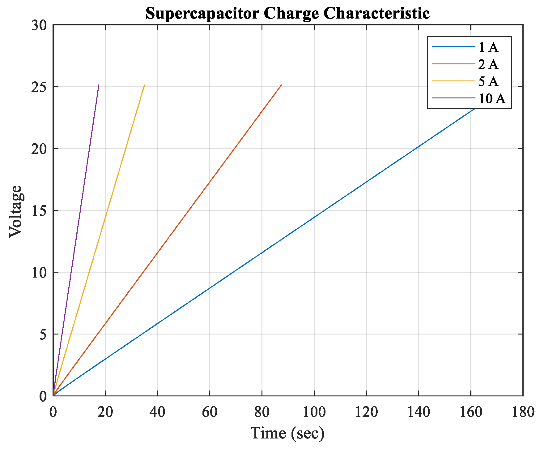
Figure 3 shows the charging curve of the supercapacitor. According to these features, the charge curve of the system was calculated as in Figure 3 [25].

2.4. DC/DC Converter Model

A bidirectional DC/DC converter is used for energy storage, charging, and discharging of the battery. The converters control charging and discharging based on the state of charge of the power source and the direction of the current [28]. The one we used in the model is a non-isolated bidirectional DC/DC converter containing an inductor, capacitor, resistor, and diode, whose circuit is shown in Figure 4 [16,23,29,30].
In order to regulate the duty cycle of the voltage and current coming from the solar cells and to reduce losses by regulating the current and voltage of the battery, a PI controller is applied to the system and a DC/DC converter is connected [31].
The power absorbed from the solar panel during the day is used to charge the battery through the DC/DC converter. In the absence of solar power, the battery discharges to power the DC load through the converter.

2.5. Solar Cell Model

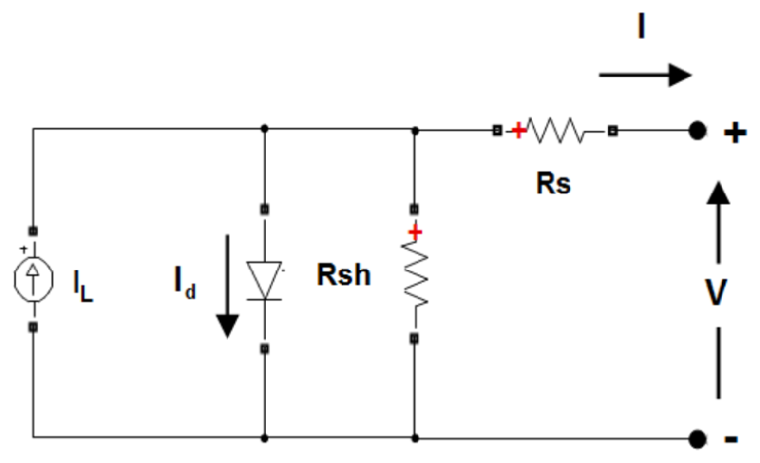
Electrical energy obtained from solar cells of the solar-powered mini VTOL UAV is the main source of the energy management system. The parameters of solar cells depend on sunlight and temperature and are non-linear, it takes time to obtain operating curves [32]. For this reason, solar cell models are developed for MATLAB/Simulink, etc. The single-diode circuit model is the most used model to calculate energy production in solar cells [28]. The solar cell model in the hybrid power propulsion system is available in the Matlab/Simulink/Simscape library. The array of the solar cell block, whose circuit is given in Figure 5, is a model that uses a current source ( I L ), diode, series resistance (Rs), and parallel resistance (Rsh), and the I-V change depends on irradiance and temperature [33,34,35].
In Simulink, the model uses Equations (5) and (6) for a single module [33]:
I d = I 0   e x p V d V T 1
V T = k T q   n l   N c e l l
I d , I 0 , V d , k, T, n l , N c e l l and q: diode current (A), diode saturation current (A), diode voltage (V), Boltzmann constant (1.3806 × 10⁻²³ J.K−1), cell temperature (K), diode ideality factor, a number close to 1, number of cells connected in series in a module and electron charge (1.6022 × 10⁻¹⁹ C), respectively.
In this hybrid power system, the solar cell, whose properties are given in Table 3, is modeled [36].
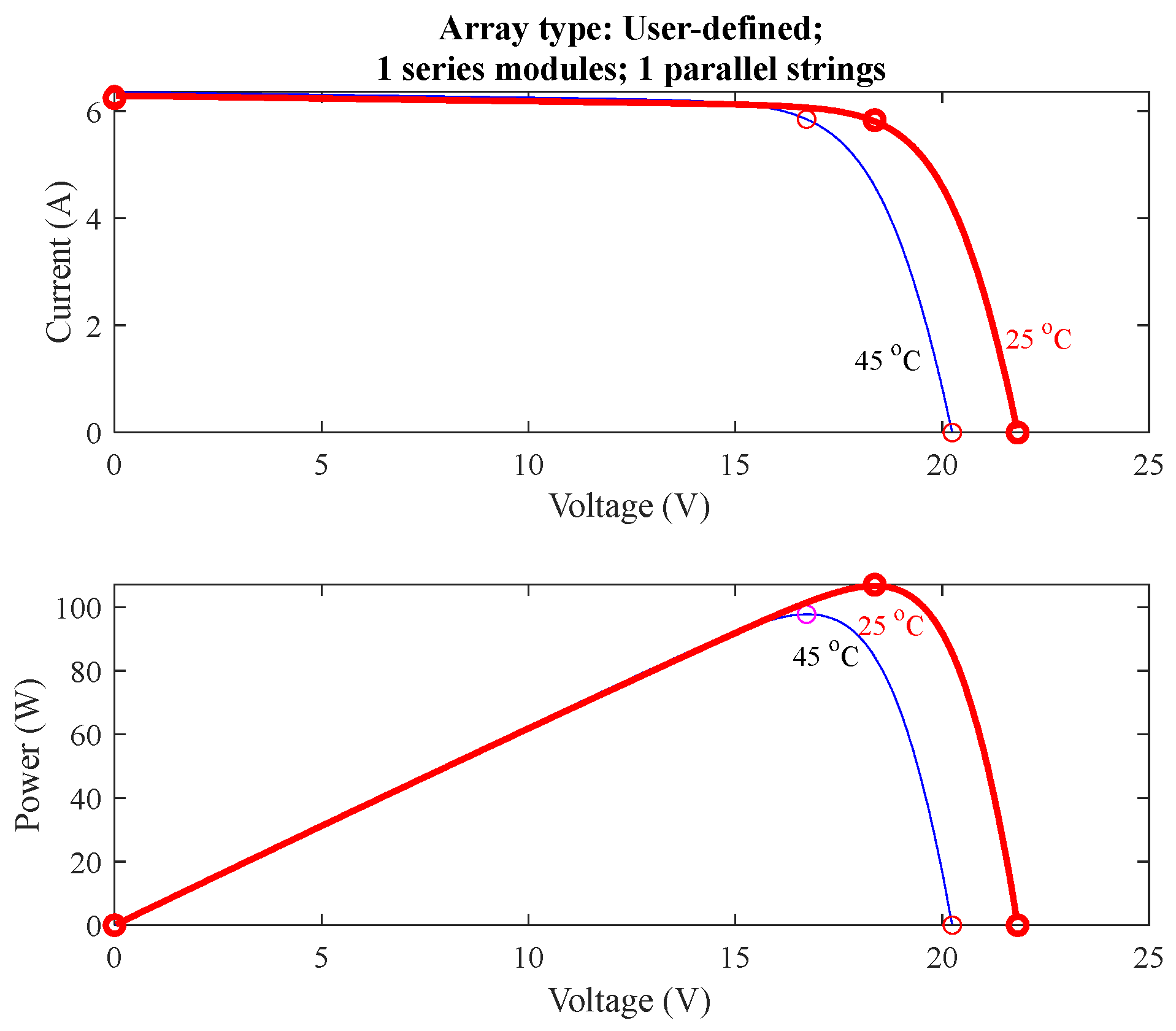
In the model, 32 solar cells are connected per module to the solar-powered mini VTOL UAV. In this configuration, the operational capacity of the UAV is calculated to be 18.368 V, and the maximum power of the cells is calculated to be 107.085 W. According to these results, the I-V and P-V change of the solar cell array of the hybrid power system are as shown in Figure 6 [25].

2.6. Power Management Algorithm

Energy management strategies are crucial for optimizing the performance and endurance of UAVs. EMS applied in UAVs are classified into three main groups: rule-based, learning-based, and optimization-based [13]. The rule-based approach has low computational loads and online applicability [37,38].
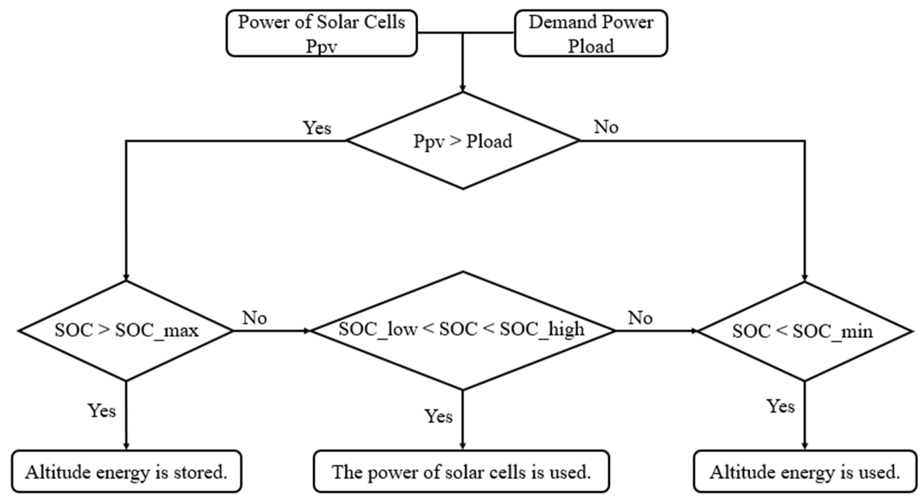
In this study, the demand power of the solar-powered mini VTOL UAV is shared between the solar cells and battery with rule-based energy management. In other words, the SMC is implemented in this study. Figure 7 shows this energy management algorithm. In addition, the cases of the energy management algorithm are listed below.
Case 1: The maximum power (Ppv) of solar cells is higher than the demand power (Pload). Since the battery state of charge (SOC) is higher than the maximum battery charge, the battery does not need to be charged. Here, excess altitude (Palt) energy can be stored as potential energy. Considering the dimensions of the unmanned aerial vehicle in potential energy storage, the maximum altitude is determined as 25 m.
Case 2: Solar cells power meets demand power. Battery state of charge (SOC) is sufficient.
Case 3: Demand power (Pload) is higher than the maximum power from the solar cells. The solar cells cannot meet the power demand alone; the part lacks solar energy is covered by the battery (Pbatt). When solar energy and battery energy are exhausted, the stored altitude energy (Palt) powers the system.

2.7. Demand Power Calculation

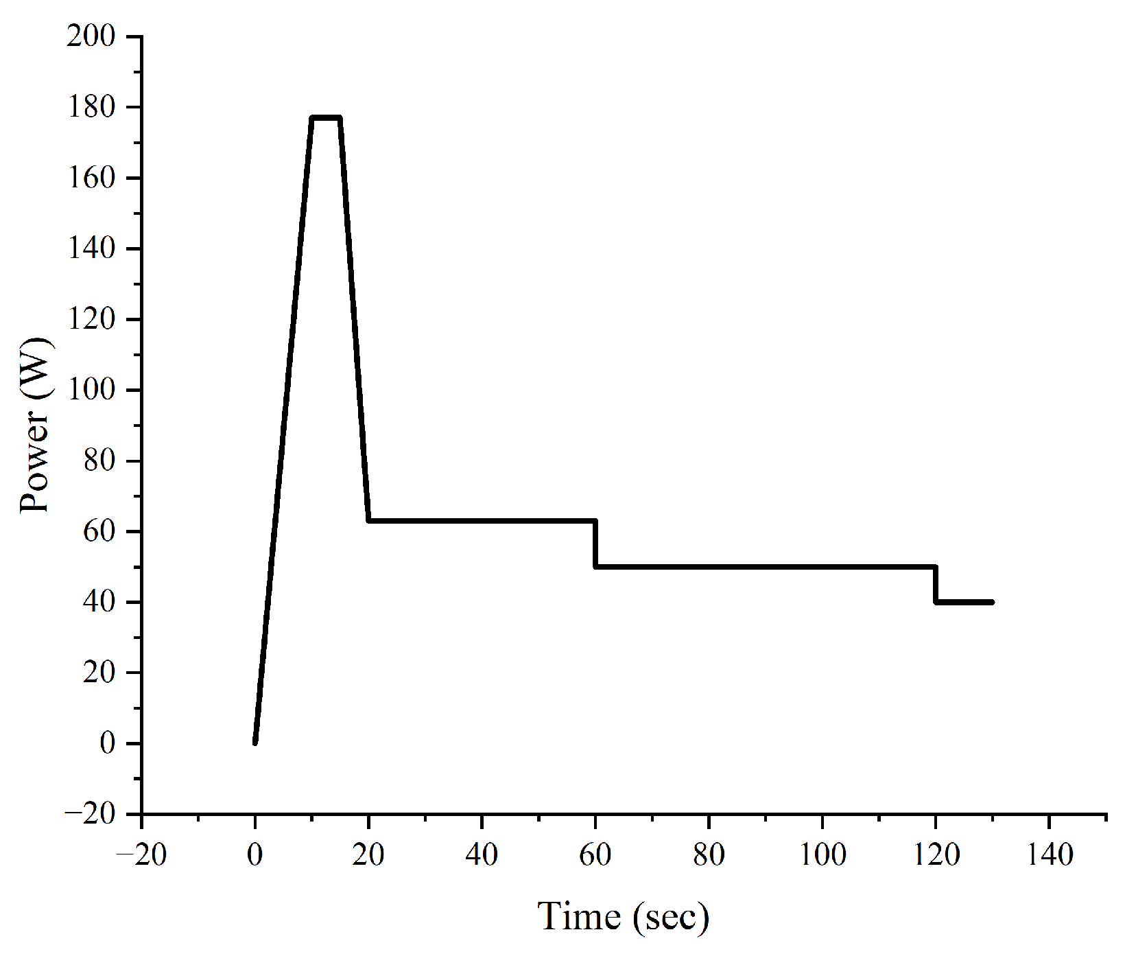
In Figure 8, the load profile has been drawn for the solar-powered mini VTOL UAV used in the hybrid power system. The thrust power requirement of the UAV depends on the flight modes of UAV, such as takeoff, climb, cruise, endurance, descent, and landing. Table 4 contains the weight information of the solar-powered mini VTOL UAV used in the calculation. Based on these parameters, the power required for takeoff, maximum speed, maximum rate of climb, and endurance mode are determined. Calculations regarding the load profile are conducted according to Equations (7)–(9).
UAV takeoff can be expressed as in [39]:
P t f = T r W   W 0   V t f
  T , W , W 0 , V t f and V: thrust, weight, aircraft takeoff weight, the takeoff velocity, and lift-off velocity, respectively.
The power required by the cruise mode [39]:
P c r = 2 W M C 3 C D 2 ρ S C L 3
W M C , S , C L , C D and ρ : mid-cruise weight, aircraft wing area, lift coefficient, drag coefficient, and air density, respectively. Additionally, the endurance mode calculation is made with Equation (8).
The power required for climb mode [39]:
R C m a x = η p r P c l i m b W 2 ρ K 3 C D , 0 W S 1 2 1.155 L D m a x
R / C m a x , L / D m a x , K and C D , 0 , the maximum rate of climb, the maximum lift to drag ratio, the proportionality constant, and the zero lift drag coefficient, respectively.

3. Results

Energy management has been applied to the system shown in Figure 1, which consists of an 8 Ah li-po battery, 7 F capacitance supercapacitor, and 107 W power solar cell pack. While the solar cells and battery are connected to the system via DC/DC converters, the supercapacitor is connected directly to the system. The demand power, whose graph is shown in Figure 8, was calculated in Section 2.7 and entered into the hybrid power system. Simulation studies were carried out in the Matlab/Simulink environment. Matlab/Simulink/Simscape (R2023b) library was used for the solar cell, battery, and supercapacitor models. The state machine control function was written with a function block in the Matlab/Simulink environment.
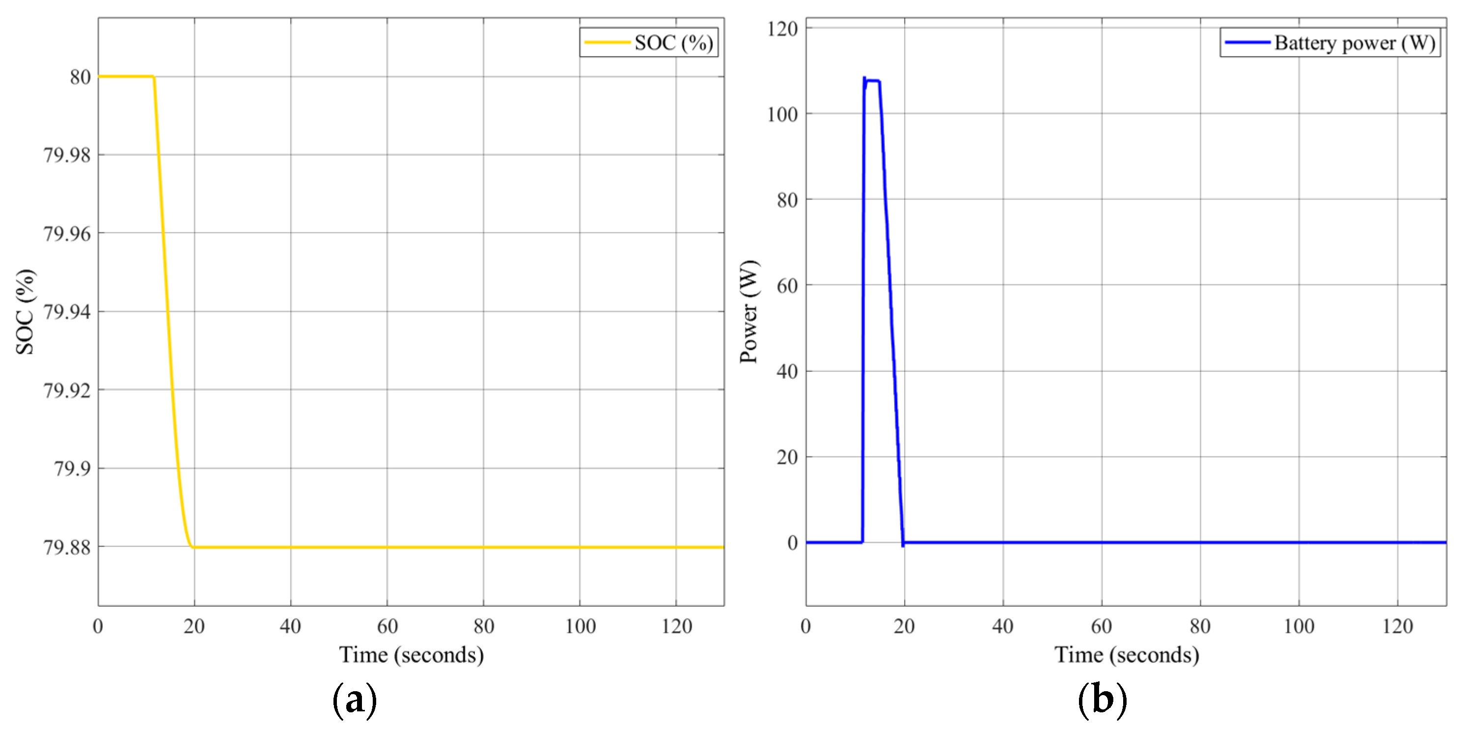
In Figure 9, the state of charge of the battery during the simulation is shown. The initial state of charge of the battery was applied as 80%. According to the chart, power was drawn from the battery between 15 and 20 s because the solar cells alone could not meet the power demand. Subsequently, the battery stopped operating when the charge level reached 79.88%. During this period, the maximum power drawn from the battery was observed to be 105 W. After the 20th second, the power produced by the solar cells exceeded the demand power and the battery was not used.
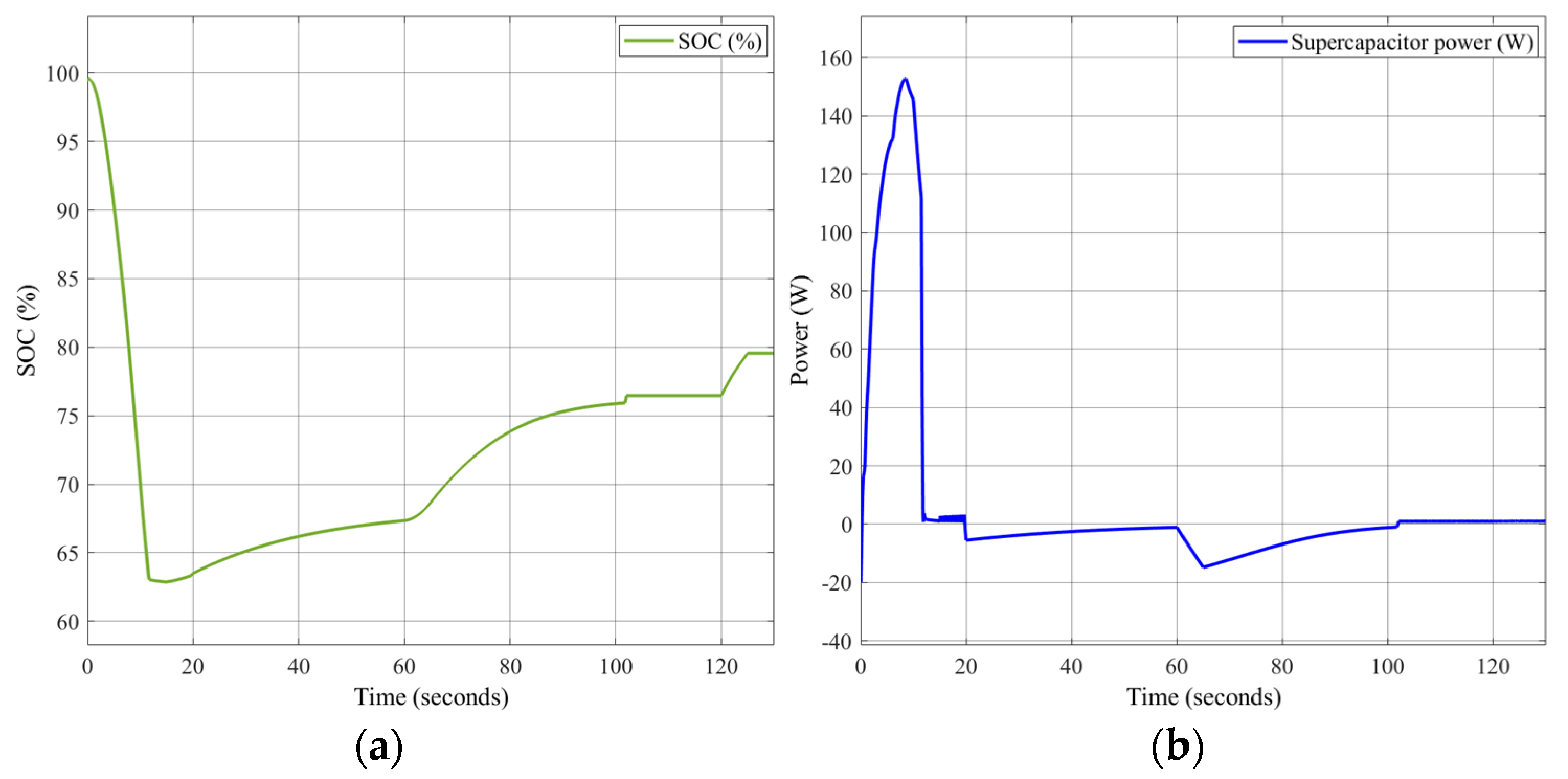
In Figure 10, the state of charge of the supercapacitor is shown. The supercapacitor is connected directly to the bus without a DC/DC converter. The initial state of charge of the supercapacitor was 98% and varied throughout the simulation. During the simulation, the supercapacitor power change was observed between −16 W and 150 W. At 40–60 and 100–130 s, the supercapacitor did not power the system, but its SOC increased because it received power from other energy components.
In Figure 11, the battery-DC converter input voltage and the DC bus voltage variation are shown. In the model, the DC converter input voltage of the battery was calculated as 15.8 V. According to the simulation, the DC bus voltage value was observed between 15.8 V and 25 V.
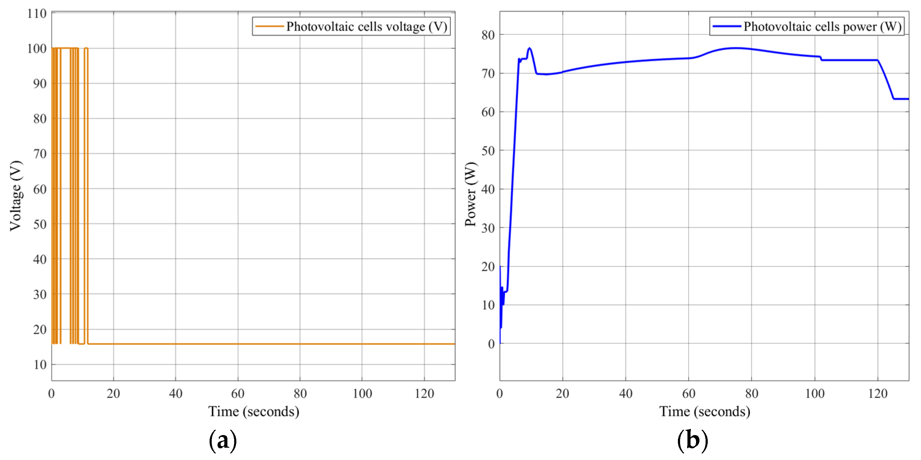
The voltage and power change of the solar cell is given in Figure 12. The solar cell voltage value was observed as 15 V. The power of the solar cell reached a maximum power of 77 W in the 10th second. In Figure 6, the value provided by the solar cells module represents the expected linear value when the system is not operational. In reality, when the system is operational, according to the energy management strategy of system, the solar cells would meet the power demand while drawing additional power from the battery and supercapacitor as needed. This results in power fluctuations during system operation. At the 10th second, the actual power was measured at 77 W, whereas the module indicates 62 W. This results in a 15 W power surplus, indicating that the system was operating more efficiently than expected.
In Figure 13, the change of power-sharing during the simulation is shown. It can be seen that the initial increase in demand power is met by solar cells and supercapacitor for up to about 10 s. Then, it is seen that the maximum demand power, which is constant for 5 s, is met by the solar cells. Then, the demand power decreased between 15 and 20 s. During this period, the power demand was met by solar cells and batteries. After the 20th second, the power produced by the solar cells was more than the demand power and this excess power was stored as altitude. The altitude energy was then used to charge the supercapacitor and battery.
With the simulation study, the demand power was met by obtaining maximum solar energy. Additionally, the charge control of the battery and supercapacitor states were performed. In the system, the battery and supercapacitor served as auxiliary energy sources when the solar cells could not meet the power demand. They also supplied power to the system when necessary to prevent damage to the solar cells under conditions such as humidity and temperature. With this operating principle and the control method we applied, excess energy was stored as altitude. Thus, we ensured efficient energy use and increased the endurance of the UAV.

4. Discussion

Gao et al. [8] developed an energy management algorithm for a system consisting of a lithium-sulfur battery and solar cell for a high altitude long endurance (HALE) type UAV with a mass of 35 kg and a wingspan of 22.5 m. In this energy management system, the energy produced by the solar cell during the day is stored as potential energy, and then this stored energy is used at night. Thus, 23.5% energy saving was achieved in the battery over a daily cycle. However, energy management was only applied to the battery, and the study was also carried out on a large UAV.
In a different previous study, Liu S. et al. [40] used dynamic climbing and solar technology together, reducing energy consumption by 32.3% and reducing the required battery weight by 6.7%. Flight speed and flight attitude angles had significant effects on optimum total energy gain.
In their study, Morton and Papanikolopoulos [41] investigated the performance of a solar-powered UAV with a 2 m wingspan for the first time in the literature. In this study, they calculated that a mini UAV with only solar panels flew for more than 10 h with solar energy.
Zhang et al. [18] applied a new method where the UAV, which has a wingspan of 1.74 m and a weight of 13.5 kg, has a hybrid system consisting of solar cell, fuel cell, and battery, called a fuzzy state machine (FSM), which is a combination of state machine strategy and fuzzy logic strategies. In the study, a full simulation model for the UAV was created in the MATLAB/Simulink program. In the study, a fuel cell was used as the main energy source, and the solar cell and battery were used as auxiliary sources. According to the simulation results, it was observed that the FSM strategy provides 26.7% savings in hydrogen consumption compared to the constrained thermostat control (CTC) strategy. Additionally, orbital optimization was performed in the study.
Lee et al. [42,43] modeled a hybrid system consisting of solar cell, fuel cell, and battery of a UAV with a wingspan of 6.4 m and a weight of 18 kg in the MATLAB/Simulink program. Both active and passive energy management techniques were applied in this hybrid system. In passive energy management, each source is directly connected to the DC bus without using any DC/DC converter. A rule-based thermostat control strategy was applied as an active energy management strategy. It was observed that, with active energy management, the battery charge level remains at 45%, while it decreases with the passive energy method. As a result of the studies, it has been proven that power distribution is more efficient in an active energy management system. This study is the first to implement an active energy management system in small unmanned aerial vehicles.
Unlike all these studies, a solar-powered mini VTOL UAV with a wingspan of 1.8 m and a weight of 3.3 kg was designed in our system. Energy management is performed on the solar cells system, which is the main energy source. We also apply control to the energy obtained from the sun, thus increasing the endurance of the UAV by dividing the power between sources and storing excess energy for use when necessary. As a result, at the point where the power generated by the solar cells exceeds the demand power, the power generated by the solar cells is measured at 70 W, while the demand power is measured at 63 W. This results in an 11.11% increase in power. This excess power is stored in the system as altitude energy. This altitude energy increases the endurance time of UAV by 1.79 h. In addition, we will be able to compare our ongoing experimental studies mentioned in Appendix A with the theoretical results we carried out in the Matlab/Simulink environment in our future studies.

5. Conclusions

In this study, energy management was studied for the hybrid system consisting of a solar cell stack, battery, and super capacitor. The aim here is to extend the endurance of UAVs by obtaining maximum power from the sun as much as possible and thus contribute to the use of renewable energy in UAVs.
Studies on rule-based and optimization-based management systems in the literature have largely focused on fuel cell systems [18,23,34,35,37,38]. Energy management is not conducted directly to the solar cell system; the solar cell is used as an auxiliary energy source. There are only studies on solar energy systems where passive energy management is applied. However, these studies are carried out on large UAVs with large wing areas in order to obtain maximum energy from the sun. In the literature, maximum power point tracking (MPPT) is used as a controller in energy management systems to obtain the maximum value from the radiation coming to solar cells and keep it constant at this value [34,44,45]. By controlling the active energy management strategy, we apply the solar energy system without the need for MPPT, and we can store the solar energy generated in excess of the demand power as altitude and benefit from the altitude energy in case the battery energy is exhausted. In addition, in the literature, in order to increase the power obtained from the sun in solar-powered mini UAVs, optimization studies are carried out not on the energy management system but rather in other areas such as sun angles [23], wing-battery topology [46], and wing profile [47,48].
In this study, the state machine control strategy was applied to the system. In future studies, we can perform a meta-heuristic energy management control by applying an appropriate optimization method, and the results of these energy management strategies can be compared.
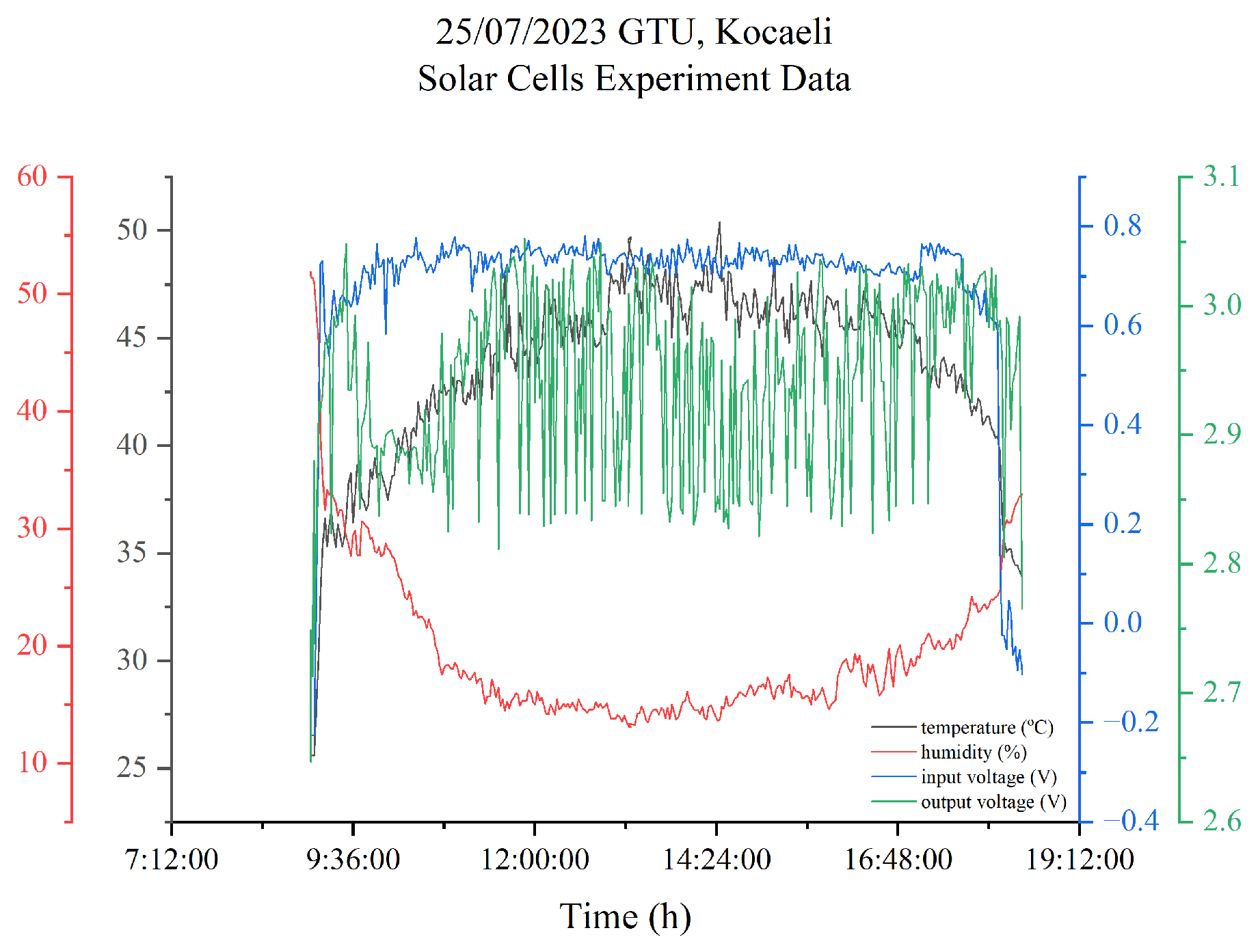
Experimental studies in laboratory environments will continue in future studies. At the same time, in the future study, the experimental data obtained in Figure A3 will be used to draw the route of the aircraft. By flying the UAV, we will be able to compare the actual results with those obtained from Simulink.

Author Contributions

Conceptualization, S.E.; methodology, S.E., H.Ç. and İ.K.; software, S.E. and H.Ç.; validation, H.Ç. and İ.K.; formal analysis, S.E. and İ.K.; investigation, S.E.; resources, S.E.; data curation, S.E. and İ.K.; writing—original draft preparation, S.E.; writing—review and editing, H.Ç. and İ.K.; visualization, S.E.; supervision, İ.K.; project administration, İ.K.; funding acquisition, S.E., H.Ç. and İ.K. All authors have read and agreed to the published version of the manuscript.

Funding

This research received no external funding.

Data Availability Statement

Restrictions apply to the datasets. The datasets presented in this article are not readily available. Because the data are part of an ongoing study.

Acknowledgments

This work was supported by the Council of Higher Education 100/2000 Doctoral Scholarship Program. This study is conducted within the scope of the Renewable Energy and Energy Storage research field.

Conflicts of Interest

The authors declare no conflicts of interest.

Appendix A

The solar-powered mini VTOL UAV, the prototype of which is shown in Figure A1, was produced in the flight systems laboratory of Gebze Technical University and solar cells were supplied for this UAV. In Table 1, Table 2 and Table 3, the battery, supercapacitor, solar cells, and other electronic components were calculated and selected in the laboratory in accordance with the UAV.
We performed solder tests on semi-flexible solar cells, the properties of which are given in Table 3. Then, we connected these two solar panels in series. We prepared the test setup in Figure A2, consisting of an ESP32, current meter, resistance, and temperature sensor. We tested the solar cells on a sunny day and obtained the data in Figure A3 for temperature, humidity, and voltage values.
Figure A1. The prototype of the solar-powered mini VTOL UAV.
Energies 17 04056 g0a1
Figure A2. The experimental setup of solar-powered mini VTOL UAV.
Energies 17 04056 g0a2
Figure A3. Solar cell experiment data of solar-powered mini VTOL UAV.
Energies 17 04056 g0a3

References

  1. Hassan, Q.; Sameen, A.Z.; Salman, H.M.; Jaszczur, M.; Al-Jiboory, A.K. Hydrogen energy future: Advancements in storage technologies and implications for sustainability. J. Energy Storage 2023, 72, 108404. [Google Scholar] [CrossRef]
  2. Le, T.T.; Sharma, P.; Bora, B.J.; Tran, V.D.; Truong, T.H.; Le, H.C.; Nguyen, P.Q.P. Fueling the future: A comprehensive review of hydrogen energy systems and their challenges. Int. J. Hydrogen Energy 2023, 54, 791–816. [Google Scholar] [CrossRef]
  3. Sharma, R.; Almasi, M.; Punia, R.C.; Chaudhary, R.; Nehra, S.P.; Dhaka, M.S.; Sharma, A. Solar-driven polymer electrolyte membrane fuel cell for photovoltaic hydrogen production. Int. J. Hydrogen Energy 2023, 48, 37999–38014. [Google Scholar] [CrossRef]
  4. Ates, E.B.; Calik, E. Public awareness of hydrogen energy: A comprehensive evaluation based on statistical approach. Int. J. Hydrogen Energy 2023, 48, 8756–8767. [Google Scholar] [CrossRef]
  5. Hossain, M.A.; Islam, M.R.; Hossain, M.A.; Hossain, M.J. Control strategy review for hydrogen-renewable energy power system. J. Energy Storage 2023, 72, 108170. [Google Scholar] [CrossRef]
  6. Milidonis, K.; Eliades, A.; Grigoriev, V.; Blanco, M.J. Unmanned Aerial Vehicles (UAVs) in the planning, operation and maintenance of concentrating solar thermal systems: A review. Sol. Energy 2023, 254, 182–194. [Google Scholar] [CrossRef]
  7. Luca, R.; Whiteley, M.; Neville, T.; Shearing, P.R.; Brett, D.J.L. Comparative study of energy management systems for a hybrid fuel cell electric vehicle—A novel mutative fuzzy logic controller to prolong fuel cell lifetime. Int. J. Hydrogen Energy 2022, 47, 24042–24058. [Google Scholar] [CrossRef]
  8. Gao, X.Z.; Hou, Z.X.; Guo, Z.; Liu, J.X.; Chen, X.Q. Energy management strategy for solar-powered high-altitude long-endurance aircraft. Energy Convers. Manag. 2013, 70, 20–30. [Google Scholar] [CrossRef]
  9. Zhu, X.; Guo, Z.; Hou, Z. Solar-powered airplanes: A historical perspective and future challenges. Prog. Aerosp. Sci. 2014, 71, 36–53. [Google Scholar] [CrossRef]
  10. Shiau, J.K.; Ma, D.M.; Yang, P.Y.; Wang, G.F.; Gong, J.H. Design of a solar power management system for an experimental UAV. IEEE Trans. Aerosp. Electron. Syst. 2009, 45, 1350. [Google Scholar] [CrossRef]
  11. Morton, S.; D’Sa, R.; Papanikolopoulos, N. Solar powered UAV: Design and experiments. In Proceedings of the IEEE International Conference on Intelligent Robots and Systems, Hamburg, Germany, 28 September–2 October 2015. [Google Scholar]
  12. Harvey, J.R.; Jarvis, R.A.; Verstraete, D.; Bagg, R.L.; Honnery, D.; Palmer, J.L. Development of a hybrid-electric power-system model for a small surveillance aircraft. In Proceedings of the 28th International Congress of the Aeronautical Sciences, ICAS 2012, Brisbane, Australia, 23–28 September 2012. [Google Scholar]
  13. Zhang, F.; Wang, L.; Coskun, S.; Pang, H.; Cui, Y.; Xi, J. Energy management strategies for hybrid electric vehicles: Review, classification, comparison, and outlook. Energies 2020, 13, 3352. [Google Scholar] [CrossRef]
  14. Cao, Y.; Yao, M.; Sun, X. An Overview of Modelling and Energy Management Strategies for Hybrid Electric Vehicles. Appl. Sci. 2023, 13, 5947. [Google Scholar] [CrossRef]
  15. Tran, D.D.; Vafaeipour, M.; El Baghdadi, M.; Barrero, R.; Van Mierlo, J.; Hegazy, O. Thorough state-of-the-art analysis of electric and hybrid vehicle powertrains: Topologies and integrated energy management strategies. Renew. Sustain. Energy Rev. 2020, 119, 109596. [Google Scholar] [CrossRef]
  16. Yang, Z.; Lei, T.; Lin, Z.; Fu, H.; Zhang, X. The Testing Platform of Hybrid Electric Power System for a Fuel Cell Unmanned Aerial Vehicle. In Proceedings of the 2018 IEEE International Conference on Electrical Systems for Aircraft, Railway, Ship Propulsion and Road Vehicles and International Transportation Electrification Conference, ESARS-ITEC 2018, Nottingham, UK, 7–9 November 2018. [Google Scholar]
  17. Savvaris, A.; Xie, Y.; Malandrakis, K.; Lopez, M.; Tsourdos, A. Development of a fuel cell hybrid-powered unmanned aerial vehicle. In Proceedings of the 24th Mediterranean Conference on Control and Automation, MED 2016, Athens, Greece, 21–24 June 2016. [Google Scholar]
  18. Zhang, X.; Liu, L.; Dai, Y. Fuzzy state machine energy management strategy for hybrid electric UAVs with PV/Fuel cell/battery power system. Int. J. Aerosp. Eng. 2018, 2018, 16. [Google Scholar] [CrossRef]
  19. Zakaria, M.; Abdallah, M.; Elshafie, M. Design and Production of Small Tailless Unmanned Aerial Vehicle. In Proceedings of the International Conference on Applied Mechanics and Mechanical Engineering, Macau, 14–15 November 2012. [Google Scholar]
  20. Cai, G.; Dias, J.; Seneviratne, L. Survey of Small-Scale Unmanned Aerial Vehicles: Recent Advances and Future Development Trends. Unmanned Syst. 2023, 2, 101–125. [Google Scholar] [CrossRef]
  21. Peciak, M.; Skarka, W.; Mateja, K.; Gude, M. Impact Analysis of Solar Cells on Vertical Take-Off and Landing (VTOL) Fixed-Wing UAV. Aerospace 2023, 10, 247. [Google Scholar] [CrossRef]
  22. Abd Rahman, Y.A.; Hajibeigy, M.T.; Al-Obaidi, A.S.M.; Cheah, K.H. Design and Fabrication of Small Vertical-Take-Off-Landing Unmanned Aerial Vehicle. In Proceedings of the 9th Eureca 2017 International Engineering Research Conference, Selangor, Malaysia, 6 December 2017. [Google Scholar]
  23. Zhang, C.; Zhang, C.; Li, L.; Guo, Q. Parameter analysis of power system for solar-powered unmanned aerial vehicle. Appl. Energy 2021, 295, 117031. [Google Scholar] [CrossRef]
  24. The MathWorks, Inc. Available online: https://www.mathworks.com/help/sps/powersys/ref/battery.html (accessed on 14 May 2024).
  25. The MathWorks, Inc. MATLAB.(2023). 23.2.0.2409890 (R2023b) Update 3; The MathWorks Inc.: Natick, MA, USA, 2023. [Google Scholar]
  26. Çınar, H.; Kandemir, I. Active energy management based on meta-heuristic algorithms of fuel cell/battery/supercapacitor energy storage system for aircraft. Aerospace 2021, 8, 85. [Google Scholar] [CrossRef]
  27. The MathWorks, Inc. Available online: https://www.mathworks.com/help/sps/powersys/ref/supercapacitor.html?searchHighlight=supercapacitor&s_tid=srchtitle_support_results_2_supercapacitor (accessed on 15 May 2024).
  28. Alazrag, A.; Sbita, L. PV System with Battery Storage Using Bidirectional DC-DC Converter. Int. J. Electr. Eng. Comput. Sci. 2023, 5, 11–21. [Google Scholar] [CrossRef]
  29. The MathWorks, Inc. MATLAB Central File Exchange. Hoo L. DC-DC Converters Using Circuitry Method. Available online: https://www.mathworks.com/matlabcentral/fileexchange/54360-dc-dc-converters-using-circuitry-method (accessed on 16 May 2024).
  30. GitHub-Malopolo/EMS-Aircraft: Energy Management System of an Aircraft Powered by FC/PV/BATT/SC. Available online: https://github.com/malopolo/EMS-aircraft (accessed on 16 May 2024).
  31. The MathWorks, Inc. Available online: https://www.mathworks.com/help/sps/ref/bidirectionaldcdcconverter.html (accessed on 16 May 2024).
  32. Nguyen, X.H.; Nguyen, M.P. Mathematical modeling of photovoltaic cell/module/arrays with tags in Matlab/Simulink. Environ. Syst. Res. 2015, 4, 13. [Google Scholar] [CrossRef]
  33. The MathWorks, Inc. Available online: https://www.mathworks.com/help/sps/powersys/ref/pvarray.html?s_tid=srchtitle_site_search_17_photovoltaic%20in%20simulink%20library (accessed on 20 May 2024).
  34. Suryoatmojo, H.; Mardiyanto, R.; Riawan, D.C.; Setijadi, E.; Anam, S.; Azmi, F.A.; Putra, Y.D. Design of MPPT based fuzzy logic for solar-powered unmanned aerial vehicle application. In Proceedings of the 4th International Conference on Engineering, Applied Sciences and Technology: Exploring Innovative Solutions for Smart Society, ICEAST 2018, Phuket, Thailand, 4–7 July 2018. [Google Scholar]
  35. Dhillon, J.; Unni, A.; Singh, N. Design and Simulation of a PV System with Battery Storage Using Bidirectional DC-DC Converter Using Matlab Simulink. Int. J. Sci. Technol. Res. 2023, 6, 1–5. [Google Scholar]
  36. SunPower Corporation Product Brochure. SunPower C60 Solar Cell. Available online: https://eshop.terms.eu/_data/s_3386/files/1379942540-sunpower_c60_bin_ghi.pdf (accessed on 20 May 2024).
  37. Xiao, C.; Wang, B.; Wang, C.; Yan, Y. Design of a novel fully-active PEMFC-Lithium battery hybrid power system based on two automatic ON/OFF switches for unmanned aerial vehicle applications. Energy Convers. Manag. 2023, 292, 117417. [Google Scholar] [CrossRef]
  38. Lei, T.; Yang, Z.; Lin, Z.; Zhang, X. State of art on energy management strategy for hybrid-powered unmanned aerial vehicle. Chin. J. Aeronaut. 2019, 32, 1488–1503. [Google Scholar] [CrossRef]
  39. Anderson, J. Aircraft Performance & Design; The McGraw-Hill Companies, Inc.: Chicago, IL, USA, 1999; p. 302. [Google Scholar]
  40. Liu, S.; Bai, J.; Wang, C. Energy acquisition of a small solar UAV using dynamic soaring. Aeronaut. J. 2021, 125, 60–86. [Google Scholar] [CrossRef]
  41. Morton, S.; Papanikolopoulos, N. Two meter solar UAV: Design approach and performance prediction for autonomous sensing applications. In Proceedings of the IEEE International Conference on Intelligent Robots and Systems, Daejeon, Republic of Korea, 9–14 October 2016. [Google Scholar]
  42. Lee, B.; Kwon, S.; Park, P.; Kim, K. Active power management system for an unmanned aerial vehicle powered by solar cells, a fuel cell, and batteries. IEEE Trans. Aerosp. Electron. Syst. 2014, 50, 3167–3177. [Google Scholar] [CrossRef]
  43. Lee, B.; Park, P.; Kim, C.; Yang, S.; Ahn, S. Power managements of a hybrid electric propulsion system for UAVs. J. Mech. Sci. Technol. 2012, 26, 2291–2299. [Google Scholar] [CrossRef]
  44. Shah, S.A.; Hamid, S.A.; Kamal, N.L.M.; Norhashim, N.; Sahwee, Z.; Azaldin, A.R.R.; Zolkifli, M.I. Experimental Evaluation of Solar Charge Controller Installed in a Solar-Powered Unmanned Aerial Vehicle (Uav). Def. S T Tech. Bull. 2021, 14, 198–210. [Google Scholar]
  45. Yilmaz, U.; Kircay, A.; Borekci, S. PV system fuzzy logic MPPT method and PI control as a charge controller. Renew. Sustain. Energy Rev. 2018, 81, 994–1001. [Google Scholar] [CrossRef]
  46. Zhang, Z.; Zhang, R.; Zhu, J.; Gao, T.; Chen, F.; Zhang, W. Integrated batteries layout and structural topology optimization for a solar-powered drone. Chin. J. Aeronaut. 2021, 34, 114–123. [Google Scholar] [CrossRef]
  47. Bakar, A.; Ke, L.; Liu, H.; Xu, Z.; Wen, D. Design of low altitude long endurance solar-powered UAV using genetic algorithm. Aerospace 2021, 8, 228. [Google Scholar] [CrossRef]
  48. D’sa, R.R. Design of a Transformable Unmanned Aerial Vehicle. Ph.D. Thesis, University of Minnesota, Minneapolis, MN, USA, 2020. [Google Scholar]
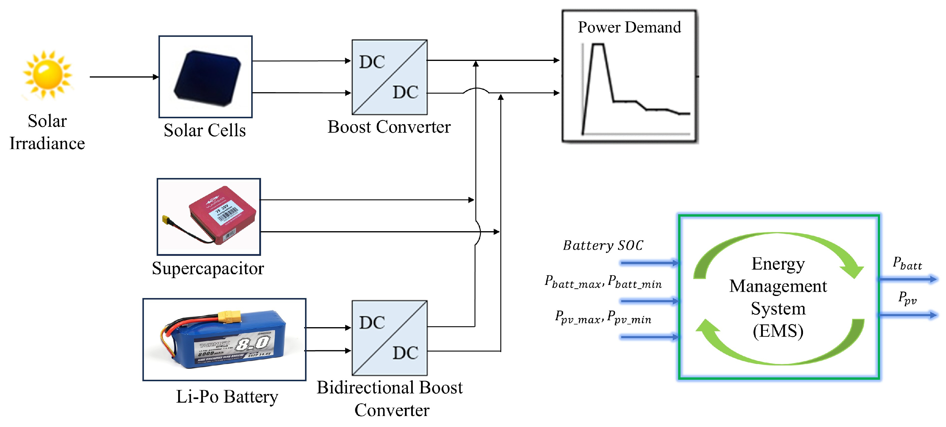
Figure 1. The hybrid power system topology for the mini solar-powered VTOL UAV.
Energies 17 04056 g001
Figure 2. The discharge curve of the battery in the hybrid power system.
Energies 17 04056 g002
Figure 3. Supercapacitor charge curve in the hybrid power system.
Energies 17 04056 g003
Figure 4. Non-isolated DC/DC boost converter section in the hybrid power system.
Energies 17 04056 g004
Figure 5. Equivalent circuit model of solar cells.
Energies 17 04056 g005
Figure 6. I-V and P-V change of the solar cell array in the hybrid power system.
Energies 17 04056 g006
Figure 7. Flow chart of the energy management algorithm for the solar-powered VTOL UAV.
Energies 17 04056 g007
Figure 8. Power demand for the UAV consisting of a hybrid propulsion system.
Energies 17 04056 g008
Figure 9. (a) State of charge for battery; (b) change of power for battery in the simulation.
Energies 17 04056 g009
Figure 10. (a) State of charge for supercapacitor; (b) change of power for supercapacitor in the simulation.
Energies 17 04056 g010
Figure 11. The change of battery-DC converter input voltage and DC bus voltage in the simulation.
Energies 17 04056 g011
Figure 12. (a) The change of power for the solar cells; (b) voltage values for the solar cells in the simulation.
Energies 17 04056 g012
Figure 13. The change in power sharing between resources during the simulation.
Energies 17 04056 g013
Table 1. Battery specifications in the hybrid power system.
ParametersValueUnit
TypeLithium-polymer-
Weight1300g
Nominal voltage14.8V
Rated capacity8Ah
Initial state of charge80%
Table 2. Supercapacitor specifications in the hybrid power system.
ParametersValueUnit
Weight279g
Max. nominal voltage25V
Rated capacity7F
Max. current10 (continuous)A
Specific energy2.2Wh/kg
Specific power2.7kW/kg
Table 3. C60 solar cell (1pc) specifications in the hybrid power system.
ParametersValueUnit
MaterialMonocrystalline semi-flexible-
Dimensions125 × 125+/−0.5mm
Area0.015m2
Mass8g
Efficiency21.8%
Max. Power3.34W
Voltage at max. power point, Vmp0.574V
Current at max. power point, Imp5.83A
Open circuit voltage, Voc0.682V
Short circuit current, Isc6.24A
Table 4. Weight estimation for solar-powered mini VTOL UAV in the hybrid power system.
ParametersValueUnit
Solar cell256g
Motor56g
Battery1300g
Weight of coated UAV (empty)1580g
Total weight for UAV (loaded)3300g
Disclaimer/Publisher’s Note: The statements, opinions and data contained in all publications are solely those of the individual author(s) and contributor(s) and not of MDPI and/or the editor(s). MDPI and/or the editor(s) disclaim responsibility for any injury to people or property resulting from any ideas, methods, instructions or products referred to in the content.