Article

CFD Research on Natural Gas Sampling in a Horizontal Pipeline

1
Research Institute of Natural Gas Technology, PetroChina Southwest Oil & Gasfield Company, Chengdu 610000, China
2
National Energy R&D Center of High Sulfur Gas Exploitation, Chengdu 610000, China
3
High Sulfer Gas Exploitation Pilot Test Center, China National Petroleum Corporation (CNPC), Chengdu 610000, China
4
School of Chemical Engineering and Technology, Tianjin University, Tianjin 300072, China
5
China Petroleum Engineering & Construction Corporation (CPECC) Southwest Company, Chengdu 610041, China
6
PetroChina Southwest Oil & Gasfield Company, Chengdu 610051, China
*
Authors to whom correspondence should be addressed.
These authors contributed equally to this work.
Energies 2024, 17(16), 3985; https://doi.org/10.3390/en17163985
Submission received: 8 July 2024 / Revised: 23 July 2024 / Accepted: 2 August 2024 / Published: 12 August 2024
(This article belongs to the Section H1: Petroleum Engineering)

Abstract

:
Accurately determining if the sample parameters from a natural gas pipeline’s sampling system reflect the fluid characteristics of the main pipe has been a significant industry concern for many years. In this paper, samples of natural gas in a horizontal pipeline are investigated. CFD is used in this work and the turbulence is considered in the simulation. Firstly, the critical diameter for particles affected by gravity within such pipeline is determined. And then, the effects of the operation pressure and velocity of sampling branches on sample parameters, and the influence of particle density on these sample parameters, are analyzed. Finally, four different structures of sample branches for natural gas in a horizontal pipeline are compared. It is found that 100 μm is the critical diameter at which particles are affected by gravity; the operating pressure of the sampling branch has a significant impact on the particle mass concentration. The particle density has little impact on the sampling system. Overall, the design of the sampling branches does not cause significant sampling errors. This study provides guidance for optimal sampling in existing natural gas pipelines and enables effective monitoring of particle impurity content and properties in natural gas.

1. Introduction

Natural gas is widely considered as an efficient and environmentally friendly energy source [1]. Its main components include methane, along with small amounts of ethane, propane, butane, hydrogen sulfide, carbon dioxide, nitrogen, and water vapor [2,3]. Generally, natural gas is transported through pipelines at high pressure [4], typically ranging from 1 to 10 MPa [5,6]. In certain conditions, the pressure can be extremely high, reaching up to 42 MPa [7]. The transportation temperature of natural gas remains normal, and it often contains a large number of solid particles during transportation [8].
These particles, commonly referred to as black powder in natural gas pipelines, raise challenges [9,10]. Incomplete removal of these particles can significantly affect downstream sections, while deposition along the inner wall of the pipeline reduces the flow area of the pipeline and conveying capacity [11]. Moreover, excessive particles passing through important equipment such as valves, meters, and compressors will cause corrosion and wear on these core components, resulting in decreased instrument accuracy and damage. If the concentration of particulate matter is too high, it even threatens the operation’s safety [1,9,12,13]. Therefore, accurate sampling from the main pipe is crucial. By connecting the main pipe and the branch pipe sampling system, the particle parameters within the main pipe can be obtained by analyzing that of the sample parameters. Once the properties of the sample particles reach a specific threshold, timely and effective measures can be taken to minimize losses. The term “particles” refers to the general term of tiny droplets and solids in a state of separation, with the size ranging from nanometers to microns, spanning up to 6 orders of magnitude [14]. Although the literature varies in defining the size range of black powder particles in natural gas, the most commonly reported range falls between 0.1 and 100 μm [10,13]. The parameters of particles’ measurement include concentration, quantity, and size distribution. There are many monitoring technologies for particulate matter in high-pressure gas pipelines, such as offline sampling analysis [15], decompression online detection [16,17], direct online detection [18], and the light scattering method [19,20]. Ensuring that particle parameters in the sampling system accurately represent those of the entire main gas pipeline is a key factor in particle measurement methodologies.
The question of particle sampling has been explored by many scholars. Chen et al. [21] simulated the gas flow field in a tube with a conic contraction and established an empirical calculation formula for particle loss during the decompression stage. Xiong et al. [15] developed a novel Null-type sampling nozzle with six sampling holes. It had been used in a natural gas compressor station with an operation pressure of 6 MPa, demonstrating its capability to measure particle concentrations and size distributions in high-pressure natural gas flows. Meyer et al. [18] developed a novel scattered light particle sizer, which required a maximum particle size below 3 μm and particle mass concentration less than 3 mg/Nm3. The device could operate at pressures up to 1.6 MPa and temperatures up to 450 °C. Seyfi et al. [13] simulated the deposition of black powder particles (1~100 μm) in a 90-degree bend of natural gas pipelines. They found that smaller black powder particles exhibited higher penetration efficiency compared to larger ones, easily following streamlines and avoiding wall deposition.
In summary, many studies have explored the flow characteristics of particles in the gas phase and corresponding sampling methods, but these studies tend more to design an additional sampling system that requires alterations to the main pipe, rather than exploring the feasibility of sampling systems by installing interfaces without significant changes to the existing main pipe. This may be a more suitable and straightforward approach for sampling in existing extensive natural gas pipelines. In recent years, with the development of computing technology and the improvement of model accuracy, the CFD (Computational Fluid Dynamics) simulation has gradually emerged and increased [22,23,24]. Stosiak et al. [25] investigated the flow resistance of fluids in helical and curved pipes through a combination of experiments and finite volume element simulations. They verified that the CFD method is suitable for examination in microflows. Karpenko et al. [26] conducted theoretical and experimental research on the fluid dynamics process in hydraulic transmission of vehicles, road construction, and mining machinery. They improved the heat dissipation effect of the brake disk by using thermal phase transition in the brake pads. The CFD method has also been applied to fluid flow and transfer.
In this paper, the sampling system of an existing horizontal pipeline is simulated.
Both the gas and particle phases in samples are extracted from four different sampling branches. And parameters of the two phases are obtained under different operation conditions. The difference between these samples and that in the main pipe is compared. To some extent, this work guides the natural gas sampling system in a horizontal pipeline and effectively monitors the content and properties of particle impurities in natural gas. This study provides guidance for optimal sampling in existing natural gas pipelines and enables effective monitoring of particle impurity content and properties in natural gas.

2. Mathematical Model

In this section, the mathematical model used in the present work is described, focusing on the governing equations and turbulence model.

2.1. Governing Equations

All flows are subject to three fundamental conservation laws: conservation of mass, momentum, and energy [27,28]. The simulation case is under high pressure and there are decompression components. So the gas phase is set as an ideal gas and it involves energy conservation.
The mass conservation equation is
ρ t + ( ρ u ) x + ( ρ v ) y + ( ρ w ) z = 0
The momentum conservation equation is
( ρ u ) t + div ( ρ u u ) = p x + τ x x x + τ y x y + τ z x z + F x
( ρ v ) t + div ( ρ v u ) = p y + τ x y x + τ y y y + τ z y z + F y
( ρ w ) t + div ( ρ w u ) = p z + τ x z x + τ y z y + τ z z z + F z
Energy conservation equation:
( ρ T ) t + d i v ( ρ u T ) = d i v ( k c p g r a d T ) + S T
where ρ is the density of the fluid; t is the time; u, v, and w are the velocity components of the fluid in the x, y, and z directions, respectively; p is the pressure acting on the fluid microelement; τ is the viscous stress; F is the volume force; T is the temperature; and ST is the viscous dissipation term.

2.2. Turbulence Model

The Shear-Stress Transport (SST) k-ω turbulence model [29,30] is used in this paper. The SST k-ω turbulence model is a modification of the k-ω turbulence model. It accounts for the transport of the turbulence shear stress in the definition of the turbulent viscosity. And it is more accurate and reliable for a wider class of flows (for example, adverse pressure gradient flows, airfoils, transonic shock waves). Aounallah et al. [31] conducted a numerical investigation of turbulence in an inclined square cavity with a hot wavy wall and compared the low-Reynolds-number k-ϵ, k-ω, SST k-ω turbulence models to the experimental data, revealing that the SST k-ω model returns superior results compared to the other RANS models. And the SST k-ω turbulent model is also often used in other studies on gas phase flow [32,33].
The turbulence kinetic energy k and the specific dissipation rate ω are obtained from the following transport equations:
( ρ k ) t + ( ρ k u i ) x i = x j ( Γ k k x j ) + G k Y k + S k + G b
( ρ ω ) t + ( ρ ω u i ) x i = x j ( Γ ω ω x j ) + G ω Y ω + S ω + G ω b
where Γk and Γω are the effective diffusivities of k and ω, respectively, Gk is the generation of k due to mean velocity gradients, Gω is the generation of the ω, Yk and Yω are the dissipation of k and ω due to turbulence, respectively, Sk and Sω are user-defined source terms, and Gb and Gωb are buoyancy terms.

3. Numerical Simulation

3.1. Geometrical Model

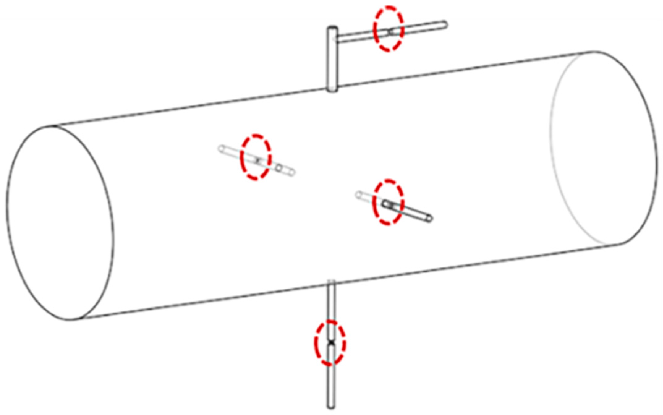
The simulation setup used in this work comprises a horizontal natural gas pipeline, along with four sampling branches installed on the main pipe. The main pipe is a cylindrical pipe with a diameter of 300 mm, and the natural gas flows from one side of the main pipe to the other at a flow rate of 10 m/s. There is a cross-section at the middle position along the length direction of the main pipe. Four different sampling branches are evenly distributed around this cross-section with 90 degrees of spacing, as shown in Figure 1.
Specific information about the four sampling branches is as follows:
Sampling branch 1: a sampling branch with a diameter of 10 mm and a length of 200 mm is directly connected to the main pipe without any interpolation;
Sampling branch 2: a sampling branch with a diameter of 10 mm and a length of 200 mm is inserted into the main pipe with an insertion length of 37.5 mm (1/4 of the main pipe radius);
Sampling branch 3: a sampling branch with a diameter of 10 mm and a length of 200 mm is inserted into the main pipe with an insertion length of 75 mm (1/2 of the main pipe radius);
Sampling branch 4: A small tube with a diameter of 15 mm and a length of 100 mm is directly connected to the main pipe without any interpolation, followed by a sampling branch with a diameter of 10 mm and a length of 200 mm. It is important to note that the installation method for this sampling branch involves mounting the sampling tube on the existing pressure gauge port, without the need to re-drill holes in the main pipe.
The above information about sampling branches is summarized in Table 1.

3.2. Numerical Setup

The physical properties of natural gas and particles (water) are shown in Table 2. In this work, ANSYS software (2020 R2) was used. The solution method for pressure–velocity coupling is the SIMPLE algorithm. The gradients are computed using the least squares cell-based method. The spatial discretization methods for momentum, turbulent kinetic energy, and specific dissipation rate are all second-order upwind schemes [8].
The inlet for natural gas fed into the main pipe is settled as velocity-inlet (uniform), while the outlet and four sampling outlets of that are treated as pressure outlets. The wall boundary condition is specified as no slip. The residual monitoring is set to be 10−5. Particle injection is realized by using the DPM (Discrete Phase Model) model [9,34], with particles composed of water. Particles with diameters of 0.1 μm, 0.2 μm, 0.5 μm, 1.0 μm, 2.0 μm, 5.0 μm, and 10.0 μm, respectively, are uniformly released from the main pipe inlet at concentrations of 10 mg/m3 for each size, totaling 70 mg/m3. The released velocity of these particles is 10 m/s, which is the same as the gas velocity.

3.3. Grid Independency Study

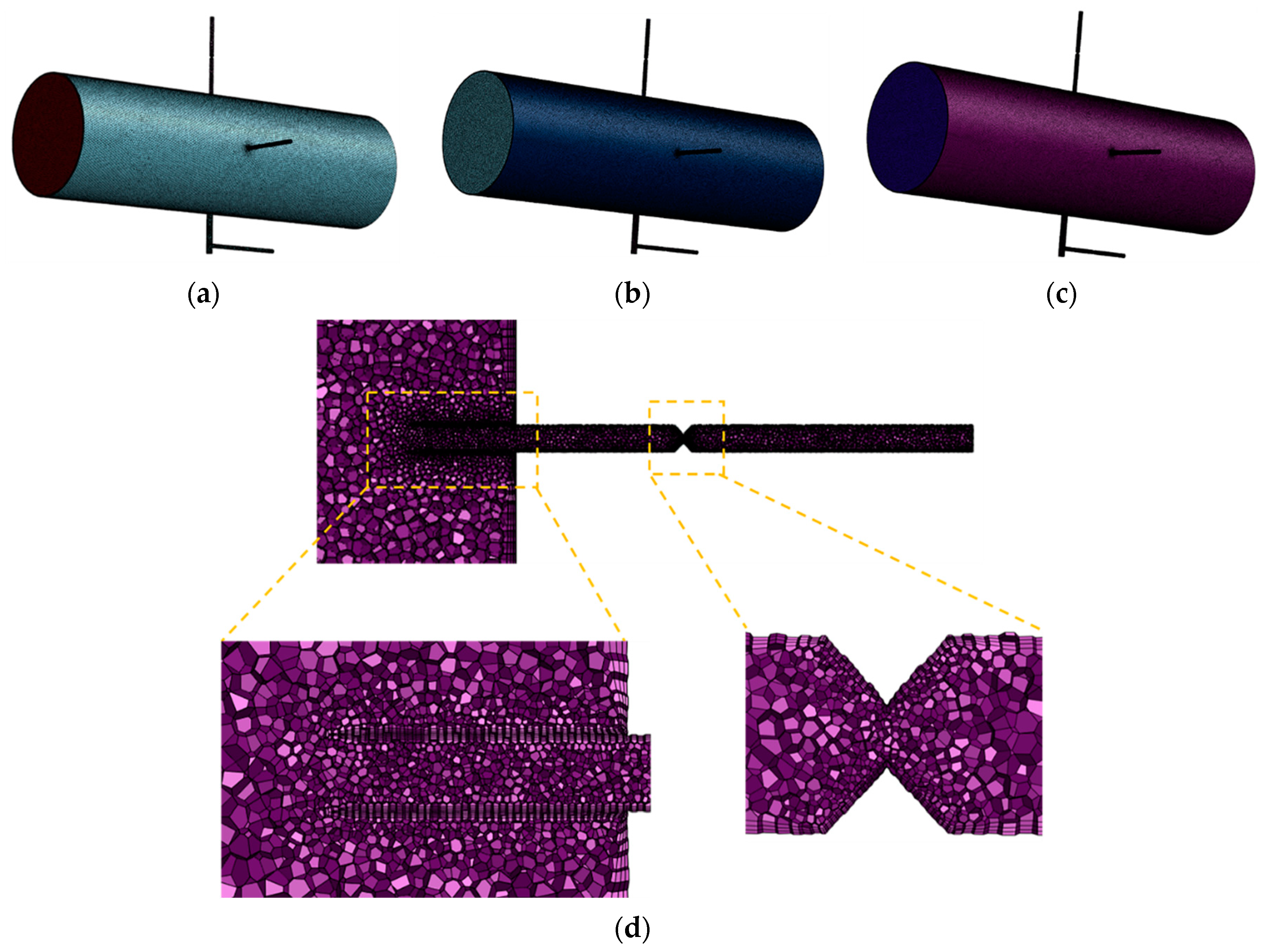
The mesh in the present work utilizes an unstructured mesh generated by Fluent Meshing 2020 R2 software. As shown in Figure 2, three grid resolutions—783,863, 1,196,035 and 1,429,798—of cells are used to confirm that the simulation results are independent of the grid used. The meshing here is polyhedral. The Local Sizing method is used to process sampling branches and reduction parts, of which the size is much smaller compared to the main pipe. For the coarse grid, the mesh sizes at the surface of the main pipe, sampling branches, and reductions are 4.5 mm, 1.2 mm, and 0.5 mm, respectively. For the medium-sized grid, the mesh sizes at the surface of the three parts are 4.0 mm, 1.0 mm, and 0.4 mm. For the fine grid, the mesh sizes are 3.8 mm, 0.8 mm, and 0.3 mm, respectively, as shown in Table 3.
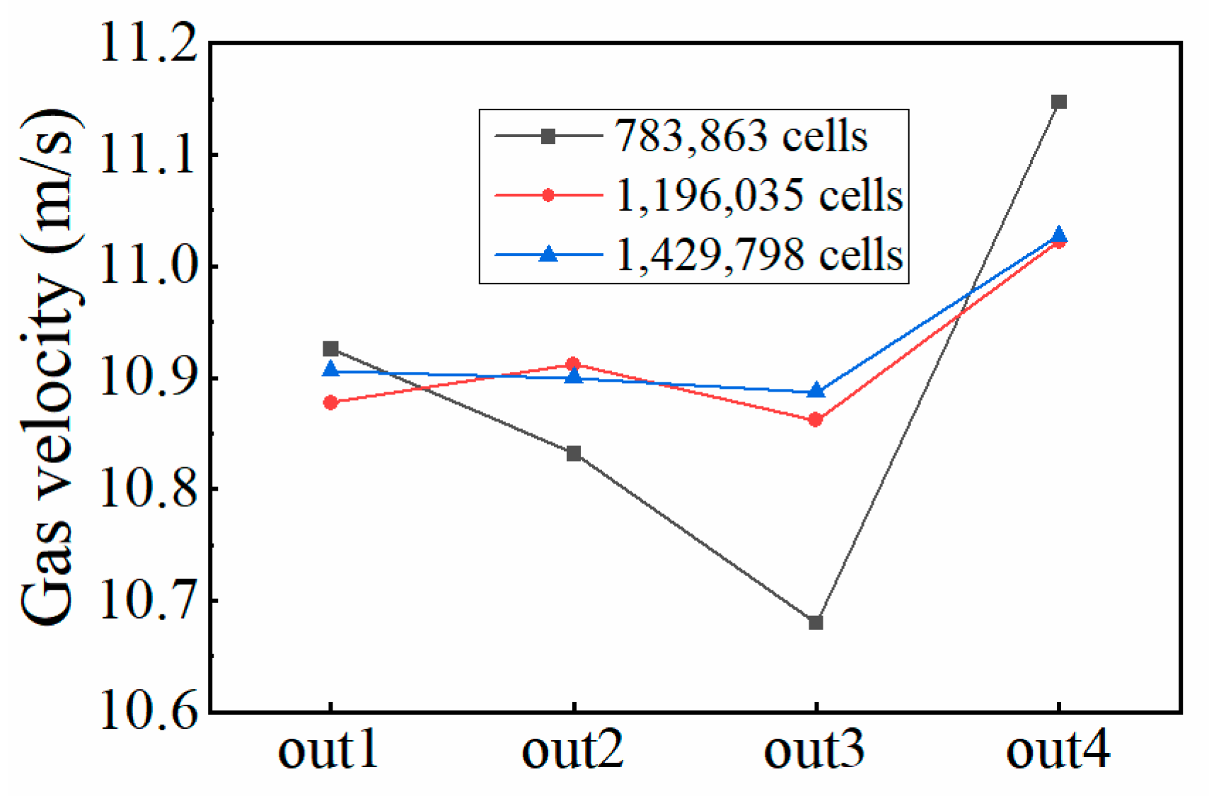
When the radius of the reduction is set to 2 mm and the outlet pressure of the sampling branches is set to 5 MPa, the gas velocities in the four sampling branches calculated by the three grids are compared, as shown in Figure 3. The results indicate that the gas velocities in four sampling branches predicted by the coarse grid (783,863 cells) differ from those of the medium (1,196,035 cells) and fine grids (1,429,798 cells), and the gas velocities of the latter two grid settings are close to each other. This consistency confirms that when the grid size is small enough, the simulation result will not change significantly with the increase in the grid number. Consequently, the medium-sized grid with 1,196,035 cells is fine enough to ensure grid independence of the results and is adopted in the following sections of this paper.

4. Result and Discussion

4.1. Analysis of the Influence of Gravity

When particles of various sizes are injected into a horizontal pipeline, larger particles may settle on the pipe walls due to gravity, potentially affecting the accuracy of sampling. Therefore, it is necessary to determine a particle size threshold to evaluate the conditions under which there is no significant deposition of particles. As shown in Figure 4, the main pipe is a horizontally placed cylindrical pipe with a size of Φ 300 mm × 2000 mm. The gas phase enters the main pipe at a uniform speed of 10 m/s from the inlet, and the particles are introduced into the main pipe at the center of the gas phase inlet, with the incident velocity matching that of the gas phase. The incident particle group sizes are 0.1 μm, 0.5 μm, 1 μm, 2 μm, 5 μm, 10 μm, 20 μm, 50 μm, 100 μm, 200 μm, 500 μm, and 1000 μm, respectively. Each particle size has the same inlet mass flow rate of 10 mg/m3. Detailed information about incident particle sizes is shown in Table 4. Operation conditions and the physical properties of the gas and particles are detailed in Table 5. In this section, the coalescence and breakup of particles are not considered, meaning each particle maintains its original size from the inlet of the main pipe to each outlet.
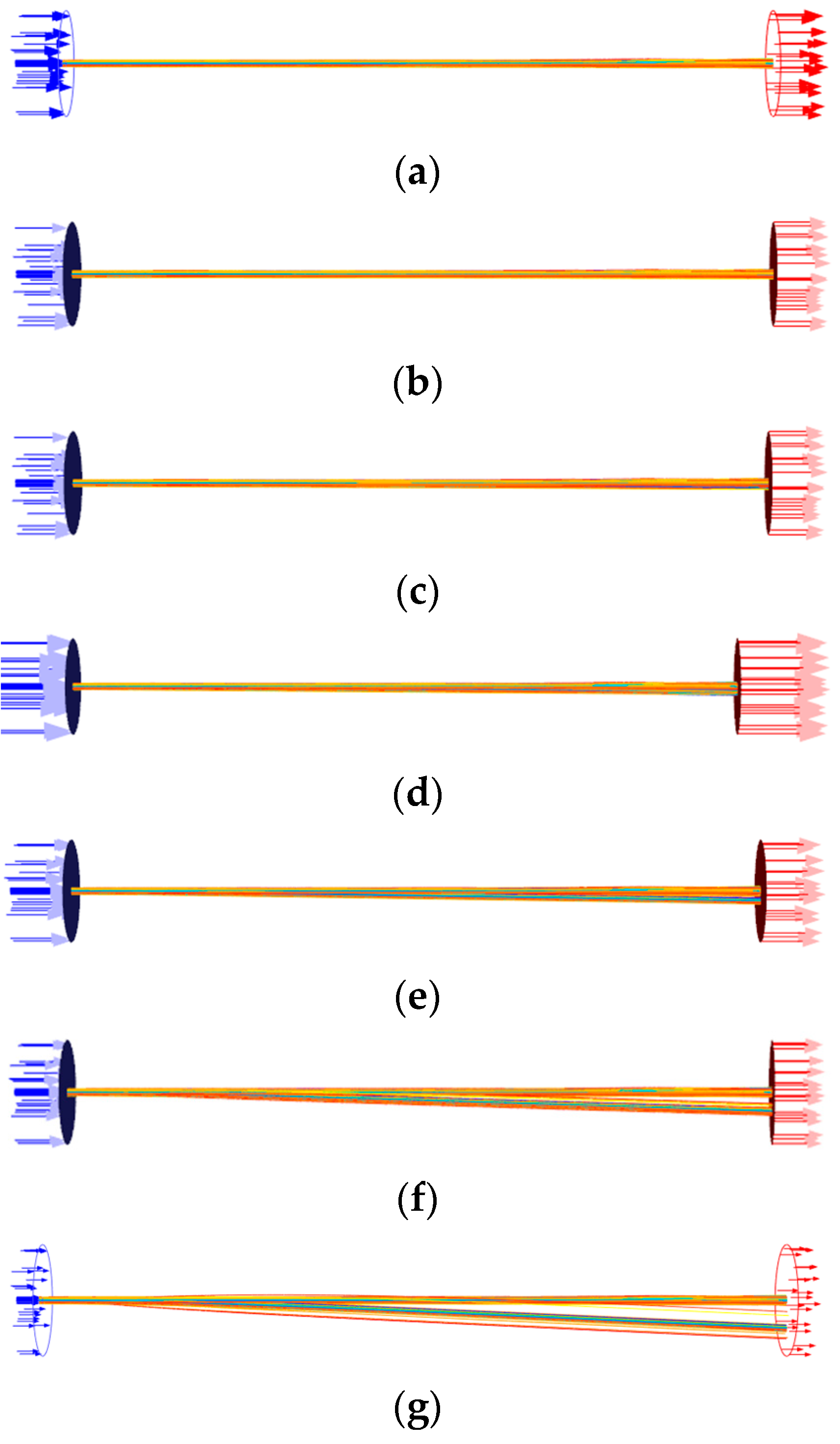
Figure 5 shows the movement trajectories of particles with different diameters. As shown in Figure 5a, particles ranging from 0.1 μm to 10 μm do not have significant axial offset when passing through the main pipe with a length of 2 m, indicating minimal effects of gravity. In addition, in order to obtain the particle size threshold affected by gravity, larger diameter particles (20 μm to 1000 μm), with the same inlet mass flow rate as the smaller diameters, are introduced, the movement trajectory of which is shown in Figure 5b–f. It is found that the larger the particle diameter, the more obvious the effect of gravity deviation. It can be concluded that 100 μm is the critical diameter; particles with diameters less than 100 μm are not affected by gravity after traveling through the horizontal main pipe, whereas those with diameters greater than 100 μm are affected. This implies that the particle size threshold is 100 μm and samples with different particle size distributions may be obtained at different locations across the main pipe cross-section.

4.2. Influence of the Sampling Operating Conditions on Particle Parameters

4.2.1. Controlling the Operation Pressure and Gas Velocity in Sampling Branches

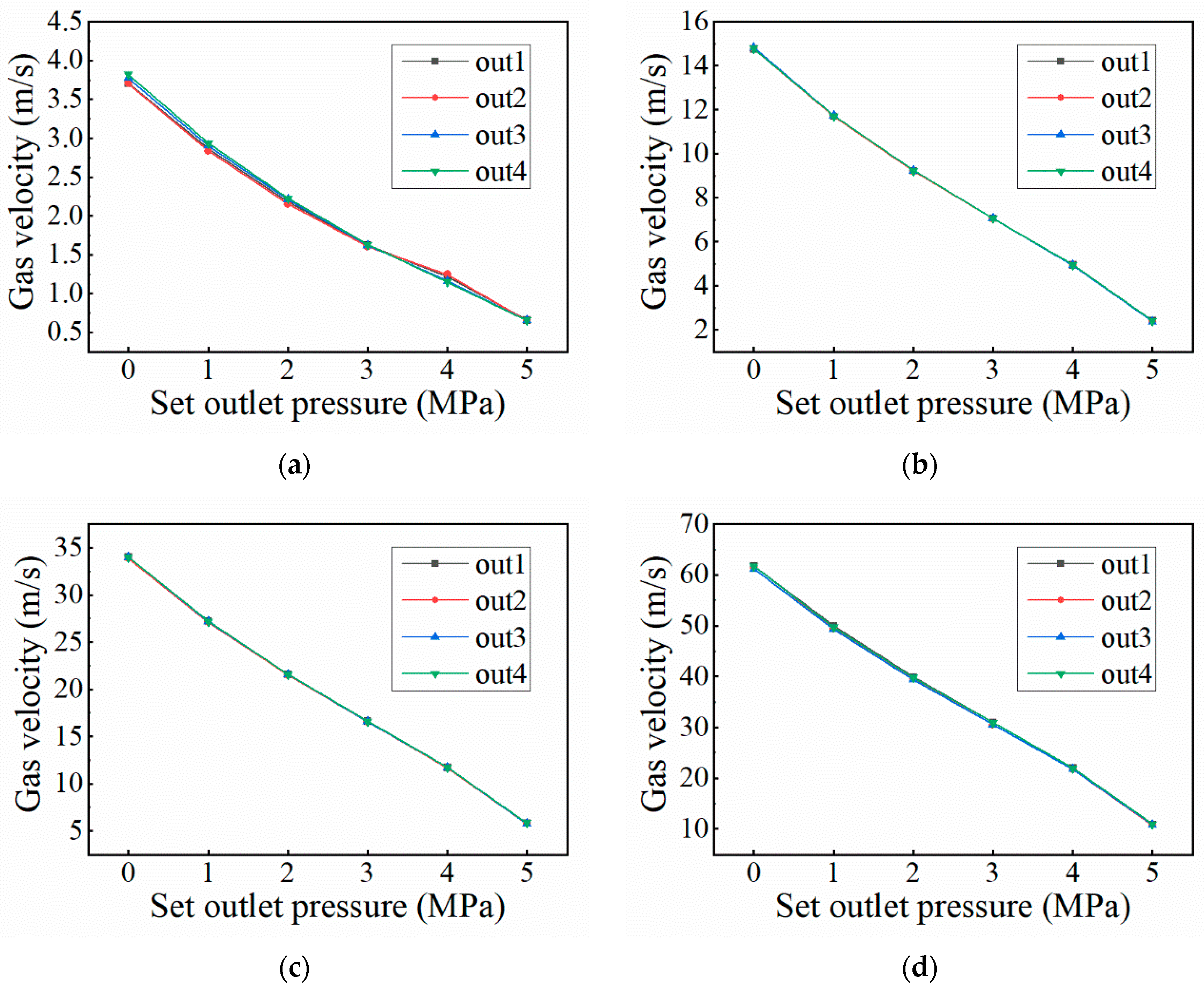
In practical engineering, the operation pressure of the sampling system is typically controlled by adjusting the opening of pressure-reducing valves located before and after the branches, ensuring that the operation pressure and fluid flow rate are maintained within the required range. To simplify the simulation, the desired operation pressure is controlled by setting the outlet pressure of the sampling system, and the desired fluid flow rate (comparable to the flow velocity of 10 m/s in the main pipe) is achieved by setting the outlet pressure and configuring reductions in various sizes at specific locations within the sampling branches. These reductions are located 100 mm away from the branch outlet, with the radius of the reduction set to 0.5 mm, 1.0 mm, 1.5 mm, and 2.0 mm, respectively, as shown in Figure 6 and Figure 7.
Figure 8 shows the gas velocity at each sampling branch outlet under four different radius reductions when the operation pressure of the sampling branches is different. The following can be concluded: (1) When the pipe reduction size is fixed, the gas velocity decreases as the outlet pressure increases. This is because the smaller pressure difference between the sampling branch and the main pipe reduces the driving force. (2) With the same pipe reduction and outlet pressure settings, the differences in gas velocities across the four sampling methods are minimal, indicating that the sampling method has little effect on the gas flow rate. Figure 9 compares the relationship between gas velocity and reduction size under different operating pressures for sampling method 4. The results show that gas velocity increases with the increase in reduction size and decreases with the increase in operating pressure. This can also be explained by the fact that the pressure difference is the driving force. From Figure 8 and Figure 9, it can be seen that the desired gas velocity for a sampling branch can be determined by drawing a horizontal line through the velocity value and finding the intersection points with the pressure setting curves. For example, a gas velocity of 10 m/s can be achieved with a combination of 2 MPa operating pressure and a 1.0 mm reduction size, with a combination of 4 MPa operating pressure and a 1.5 mm reduction size, or with a combination of 5 MPa operating pressure and a 2.0 mm reduction size.

4.2.2. Influence of the Sampling Operating Pressure

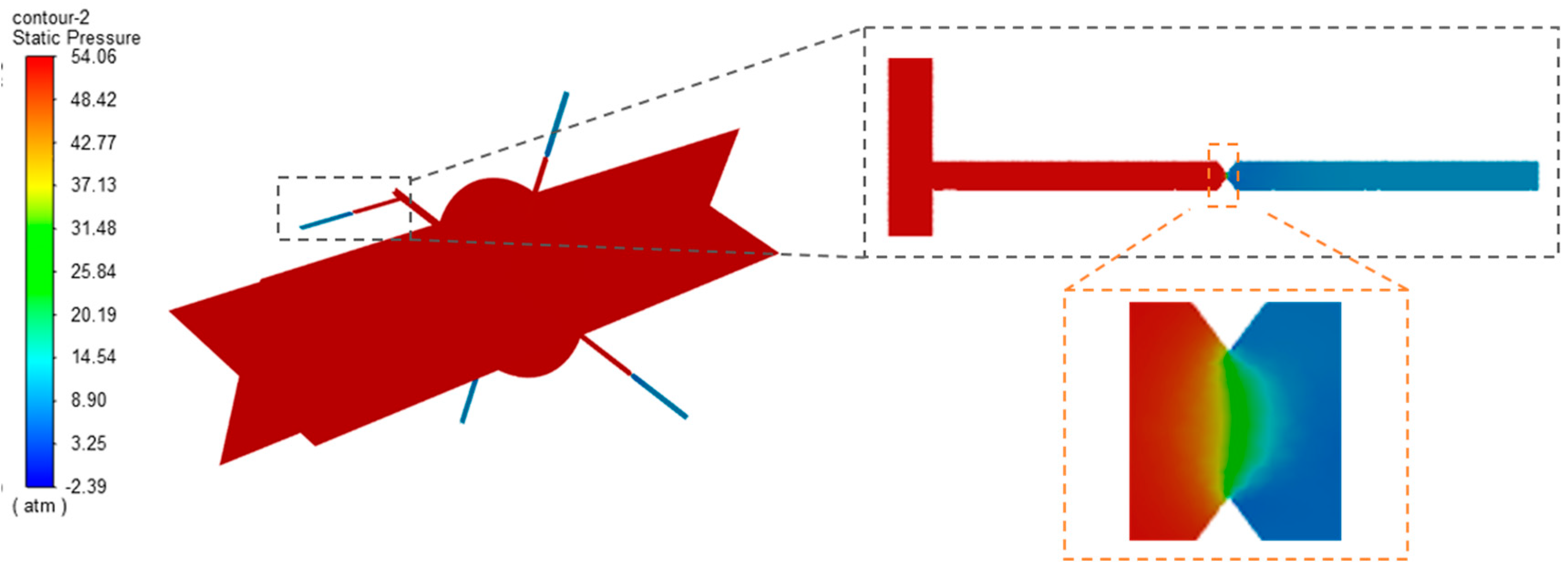
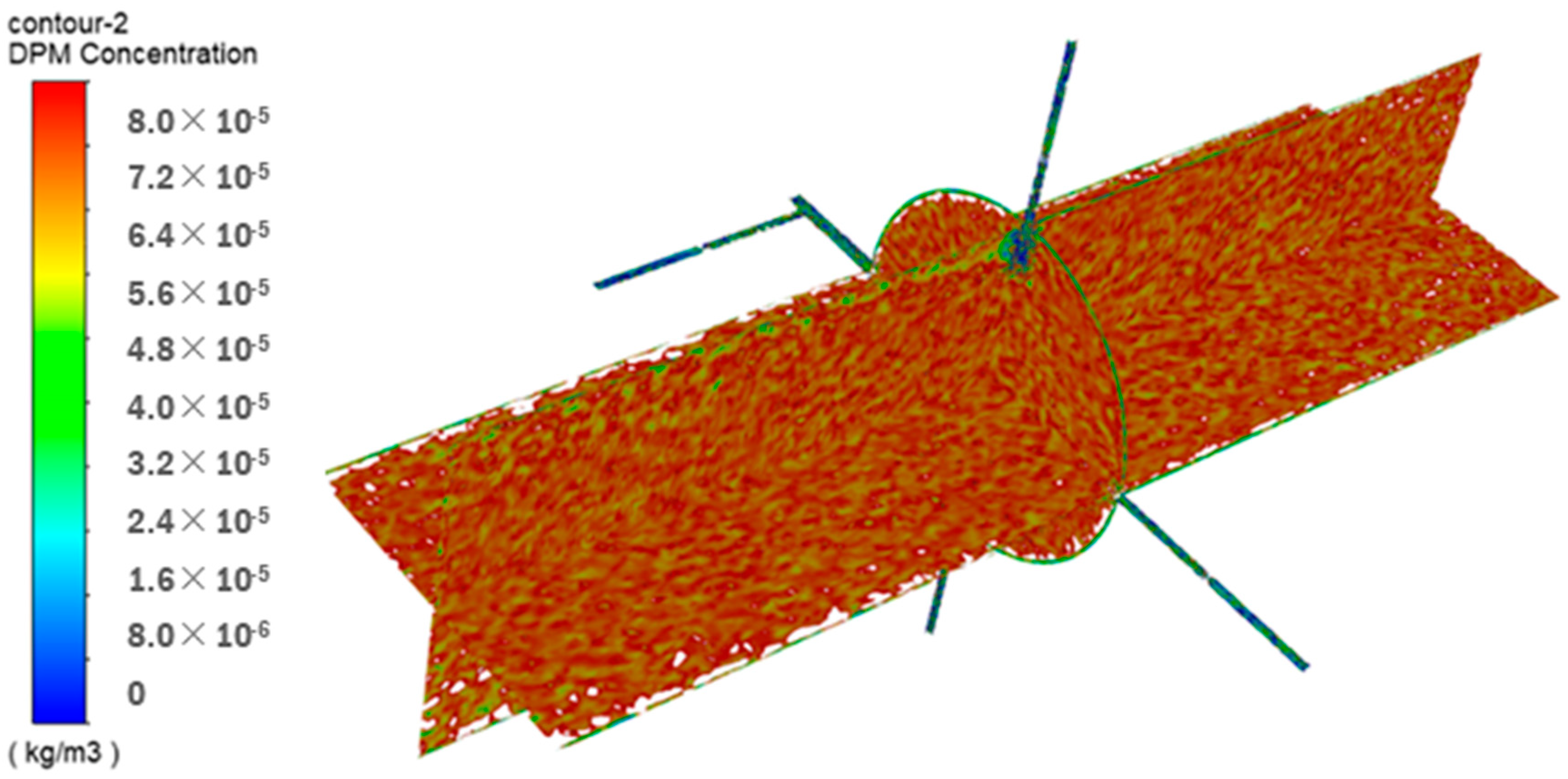
This section discusses the impact of the operation pressure of the sampling branches on the samples’ particle parameters. Figure 10 and Figure 11 show the pressure and particle mass concentration distribution on a cross-section in the main pipe and sampling branches when the operation pressure of the sampling branches is 1 MPa.
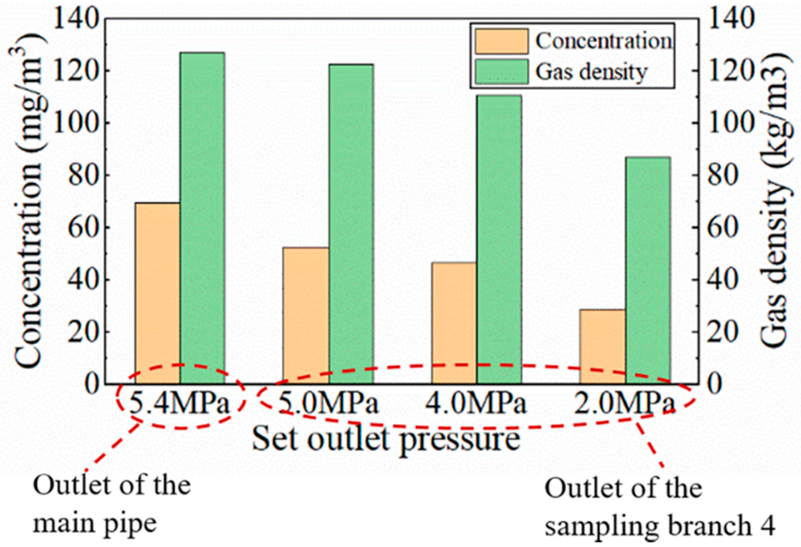
As mentioned in Section 3.2, the operation pressure for the main pipe is 5.4 MPa and the gas velocity in the main pipe is 10 m/s. As shown in Figure 9, a sampling gas velocity of 10 m/s can be achieved with different combinations of operating pressure and reduction size. Figure 12 compares the particle mass concentration in the main pipe and at the outlet of sampling branch 4 under different operation pressures. It can be seen that the lower the operating pressure, the lower the particle concentration in the sampling branch, which may be due to the influence of current local gas density. Since the gas phase is considered an ideal gas in both simulation and actual conditions, the gas density decreases with the decrease in operating pressure, thereby affecting the number of particles carried in the gas. This suggests that in actual measurements, the operating pressure in the sampling branch can be set differently from that in the main pipe, but it is necessary to calculate the true particle concentration in the main pipe from the measured value in the sampling branch by converting it for gas density. However, more experimental and simulation data are needed to fit and validate the correlation equation regarding this issue. We will further explore this in following research studies.
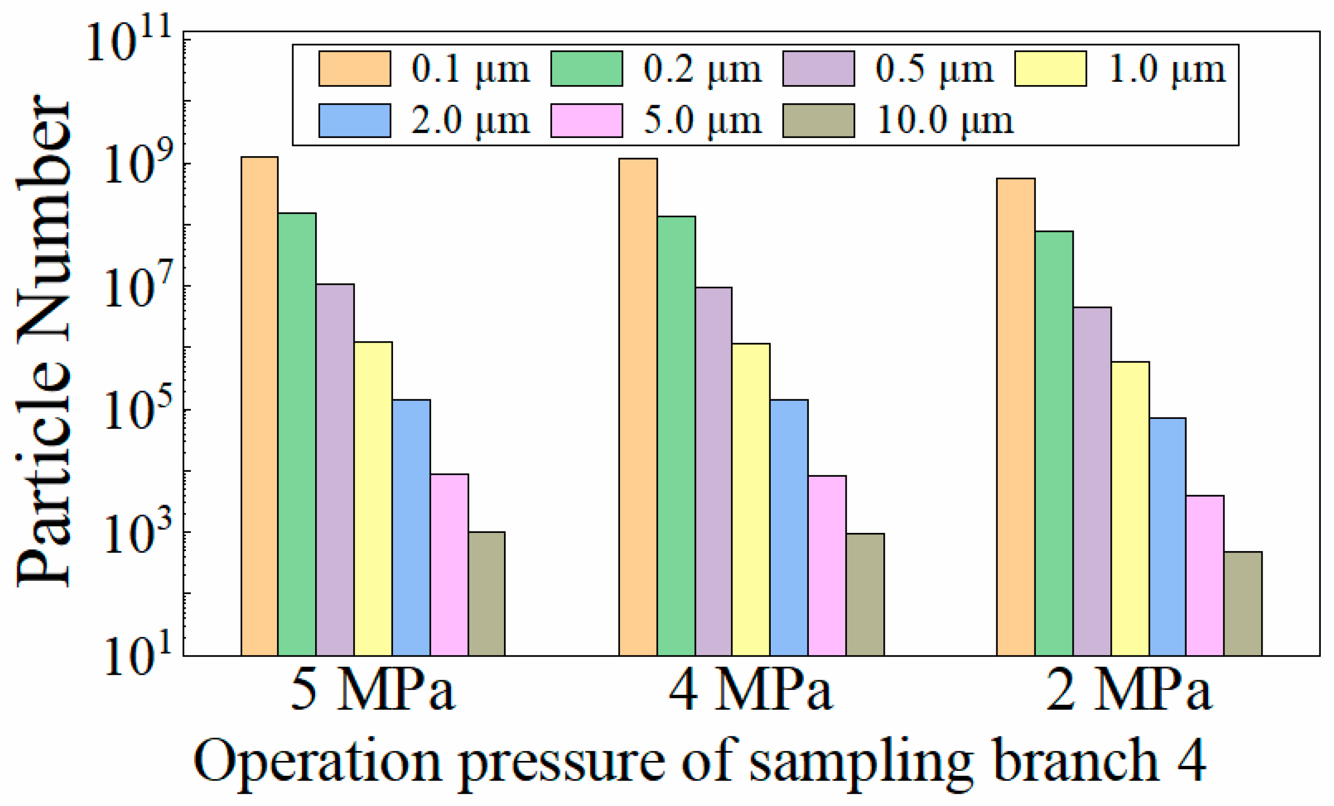
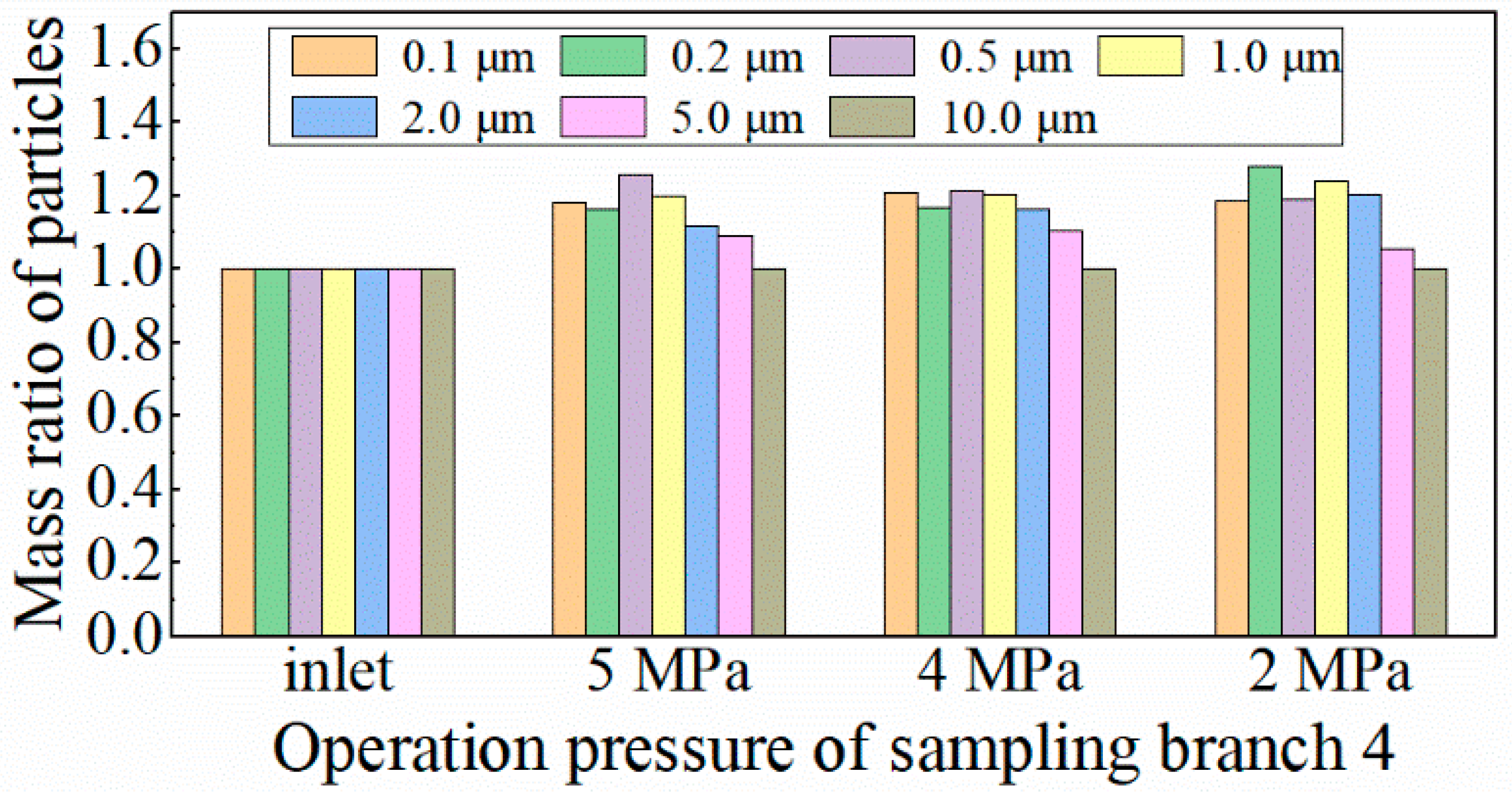
Figure 13 and Figure 14 show the particle number and mass ratio distributions of different particle diameters at the outlet of sampling branch 4 under different operating pressures, respectively. It can be seen that under different sampling operating pressures, the particle number distribution generally remains the same as in the main pipe, while the mass distribution shows slight differences. Considering that the existing particle size measuring instruments mainly measure the number distribution, this indicates that the operating pressure has little effect on measuring particle size distribution.
From Figure 12, Figure 13 and Figure 14, it can be seen that in actual measurements, the operating pressure in the sampling branch can be set differently from that in the main pipe. The measurement results of particle size distribution are similar to those in the main pipe, but the particle concentration measurement results need to be converted by gas density to obtain the true value in the main pipe.

4.2.3. Influence of Sampling Velocity

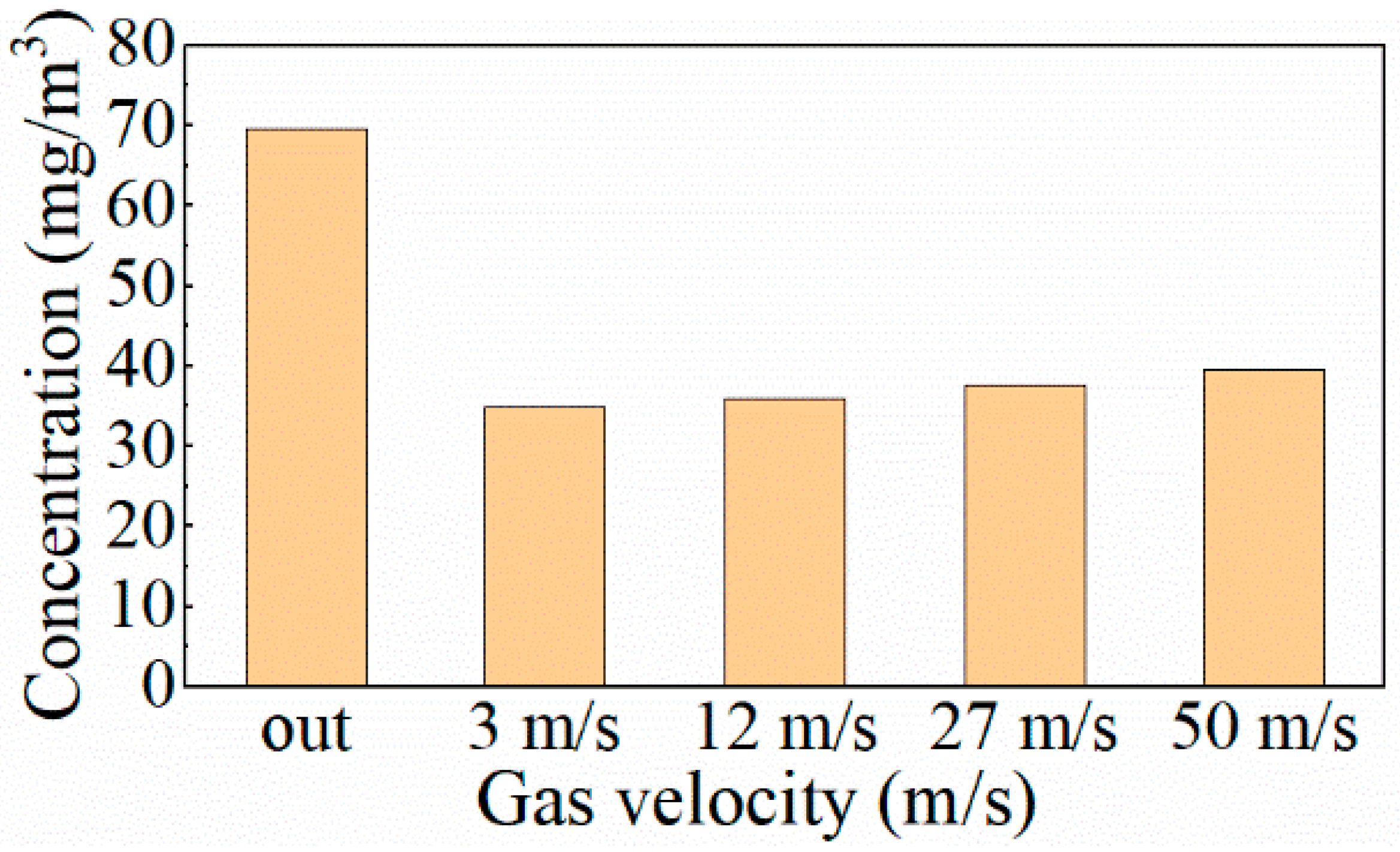
When the operating pressure of the sampling branch remains constant, the gas velocity can be controlled by setting different reduction sizes, as shown in Figure 9. When the operating pressure of the sampling branch is 1 MPa, the gas velocity ranges from 3 m/s to 50 m/s, as indicated by the red curve in Figure 9. Figure 15 shows the particle mass concentration in the main pipe and at the sampling branch outlet under different gas velocities. The results indicate that the particle concentration in the branch is lower than that in the main pipe. When the gas velocity in the branch increases from 3 m/s to 50 m/s, the particle mass concentration at the outlet only increases by about 10%. This may be due to the fact that the particle mass concentration is mainly related to gas density, and the overall gas density decreases after pressure reduction in the sampling branch.
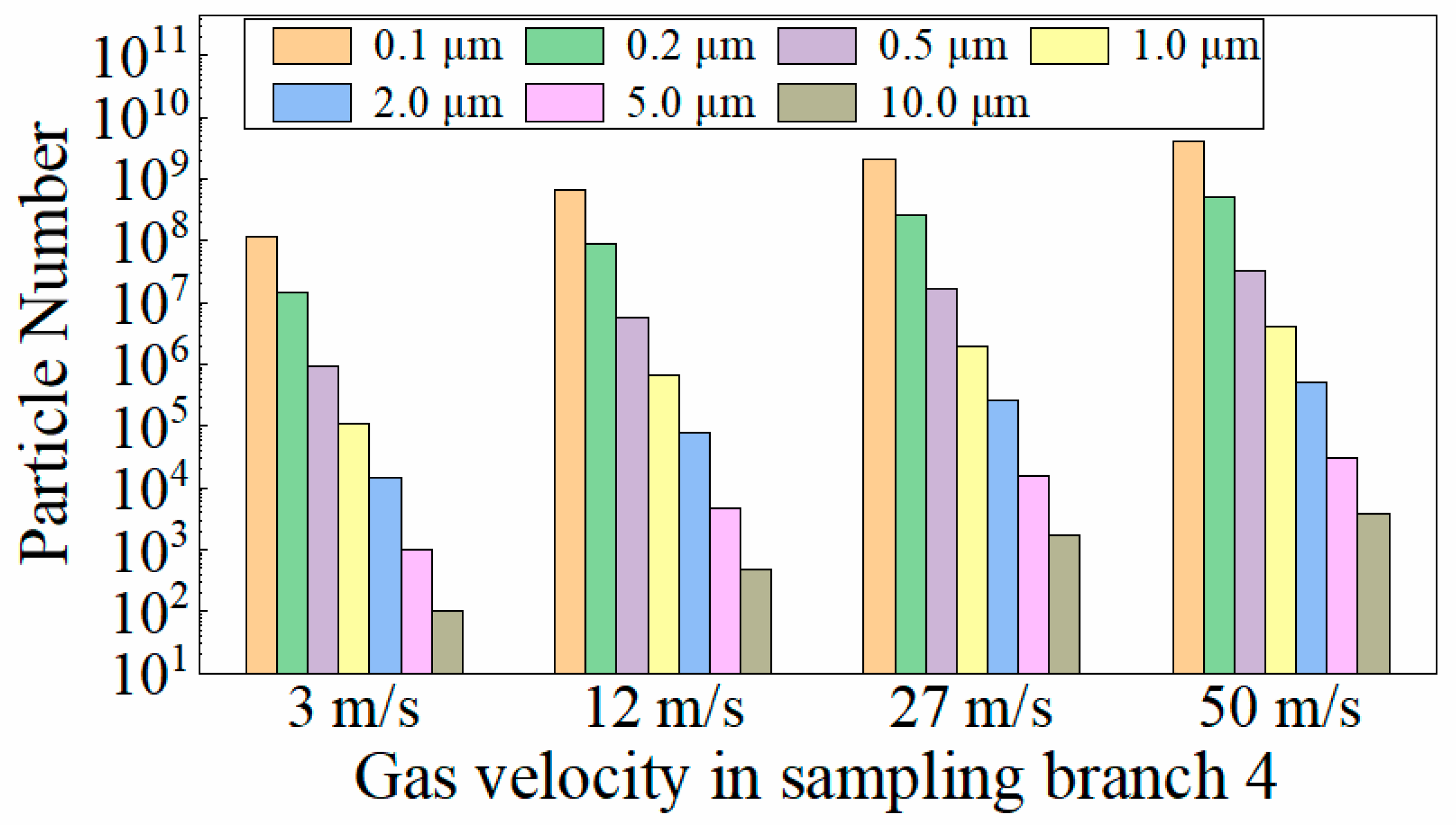
Figure 16 and Figure 17 show the particle number and mass ratio distributions of different particle diameters at the sampling branch outlet under different gas velocities, respectively. Similar to Figure 13 and Figure 14, the particle number distribution generally remains the same as in the main pipe under different gas velocities, while the mass distribution shows slight differences.
Combining Figure 15, Figure 16 and Figure 17, it can be seen that the gas velocity in the sampling branch has a minimal impact on particle concentration and particle size distribution. In actual measurement operations, it is recommended to maintain the gas velocity within the allowable range of the measurement instruments.

4.3. Influence of Particle Density on Particle Parameters

In the previous simulation, the particle is always set to water, and its density defaults to the density of water, which is 1000 kg/m3. However, in actual natural gas, there are various types of impure particles with a wide range of density. Therefore, to investigate the influence of particle density on the sampling system, it is set to 200 kg/m3, 500 kg/m3, 1000 kg/m3, and 1500 kg/m3 respectively. The reduction radius set in the sampling branches is R = 1 mm. The particle mass concentration at the main pipe inlet remains the same as that mentioned in Table 1. The outlet pressure of the sampling branches is set to be 3 MPa, 2 MPa, 1 MPa, and 0 MPa. The gas velocity, particle mass concentration, and particle number at the outlet of each sampling branch are simulated.
Figure 18 shows the relationship between gas velocity and particle density in the sampling branch under different operating pressures. It can be seen that the particle density has little effect on the gas velocity in the natural gas sampling system. This may be because the content and size range of liquid particles carried in natural gas are relatively small compared to the gas phase. The properties of the particles themselves do not directly affect the gas phase, and the interaction between the two phases is more like a single-phase coupling of gas-to-liquid. Figure 19 shows the relationship between particle concentration and particle density in the sampling branch under different operating pressures. The results indicate that, at the same operating pressure, particle concentration hardly changes with particle density. Additionally, particle concentration increases with the increase in operating pressure, similar to the conclusion in Figure 12. Figure 20 shows the particle number distribution of seven particle sizes in the sampling branch under different particle densities. It can be seen that, under different particle densities, the particle size distributions in the sampling branch and the main pipe are similar.
Combining Figure 18, Figure 19 and Figure 20, it can be seen that the particle density has little impact on the sampling system, indicating that measurement deviations in sampling are not related to the type of liquid.

4.4. Influence of the Structure of Sample Branches

In this section, particle mass concentrations and particle numbers of each size at four different sample branches when the gas velocity is set at 10 m/s are analyzed.
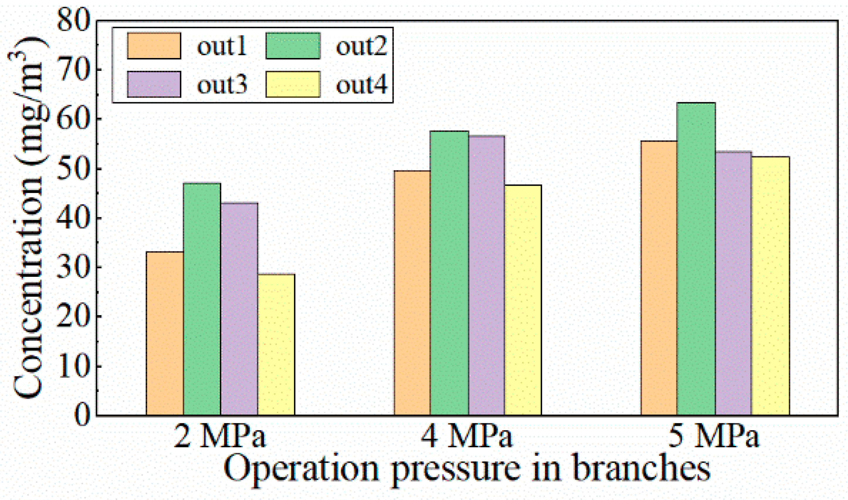
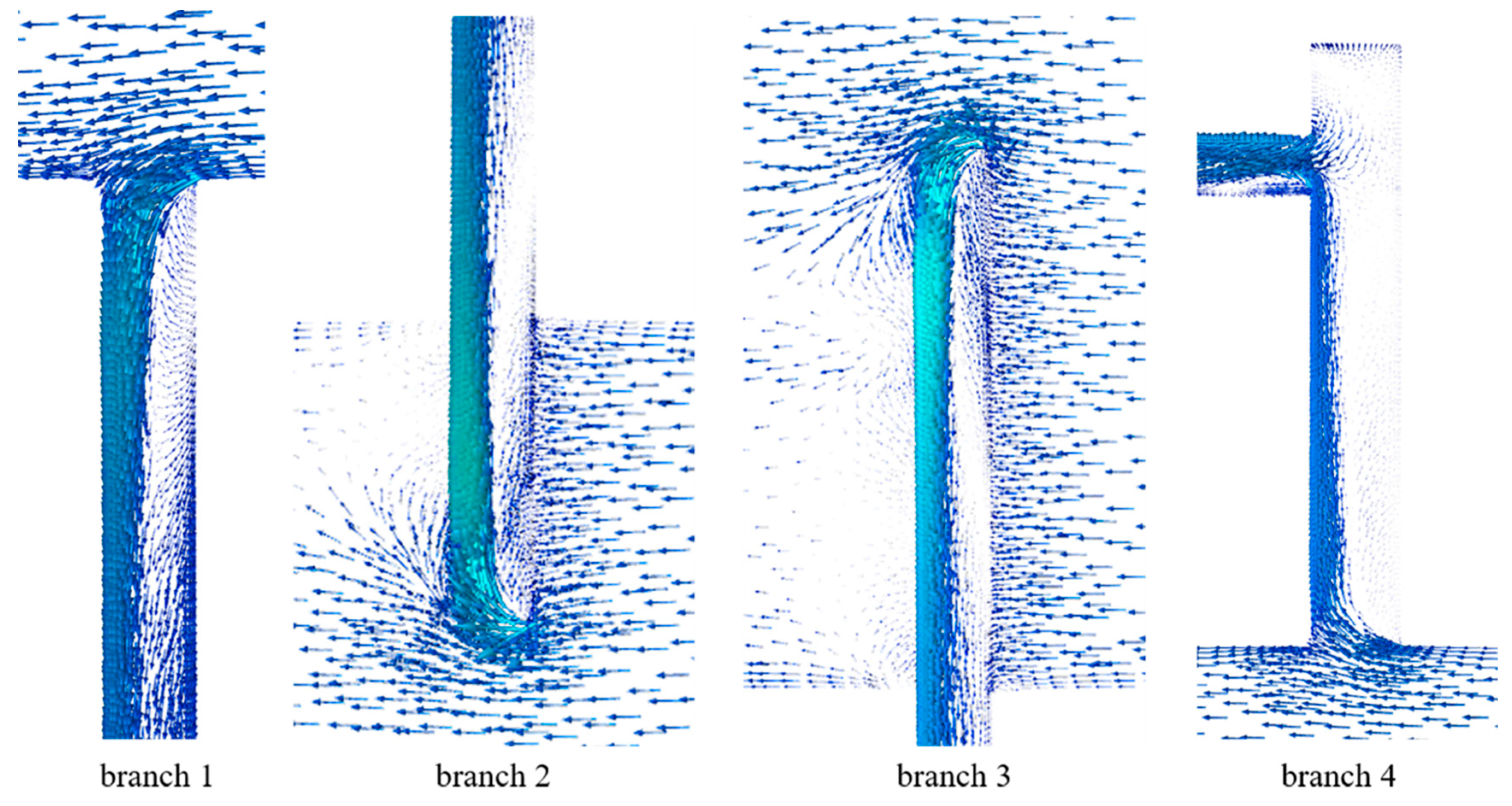
Figure 21 is the comparison of particle mass concentration of four types of branches at different operation pressures. An analysis of Figure 21 reveals that the particle mass concentration at Branch 2 and Branch 3 is usually higher than that of Branch 1 and Branch 4. This difference between the above will be greater when the operation pressure of sampling branches is smaller. This suggests that interpolating the sampling branch into the main pipe will cause a slight increase in particle mass concentration at the branch outlet. This may be because the insertion of the sampling branch obstructs particles on the windward side, causing them to aggregate on the windward face of the interpolated tube and, due to vortices, enter the sampling branch more easily. For sampling branches not interpolated into the main pipe, the particles are more likely to continue flowing in the main pipe rather than deviating into the sampling branch. This can be observed from Figure 22, showing the velocity vector at the entrance of the sampling branch inserted into the main pipe.
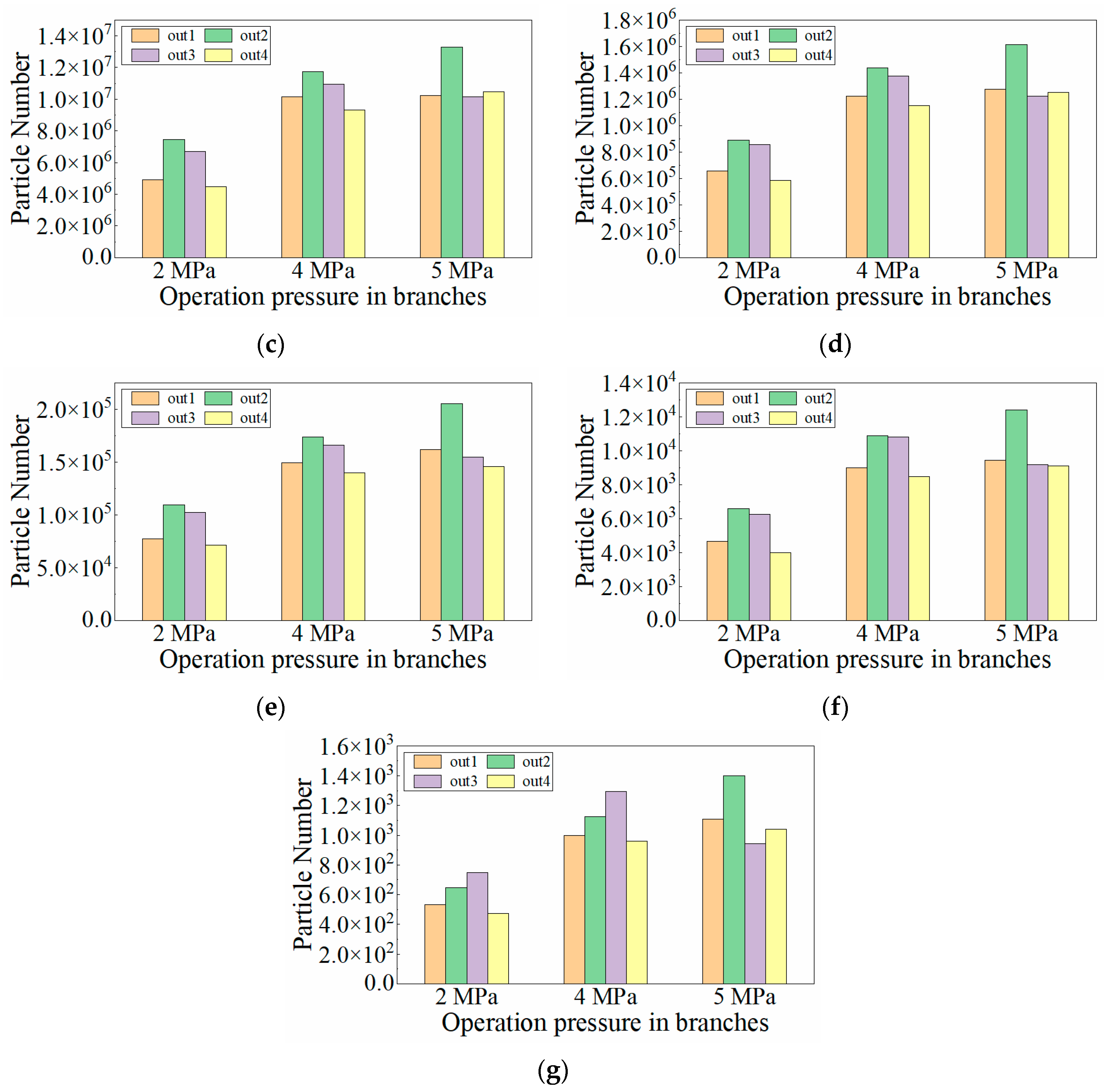
Figure 23 shows the number of particles, with seven sizes in four types of sampling branches, when the gas velocity in the branches is 10 m/s. Under almost all operating conditions, the particle numbers at the outlets of the four sampling branches are quite similar, but the trend remains that Branch 2 > Branch 3 > Branch 1 > Branch 4. This result aligns with the previously mentioned effect of branch insertion. Additionally, the generally larger particle number in Branch 2 compared to Branch 3 may be due to the longer insertion length of Branch 3, as suggested in Figure 22, which does not promote particle aggregation at the branch inlet but rather hinders more particles from entering the branch.
Overall, from Figure 21, Figure 22 and Figure 23, it can be seen that while different sampling branch designs can influence the sampling results, this effect is negligible compared to the impact of the sampling operation pressure.

5. Conclusions

In this paper, samples of natural gas in a horizontal pipeline are investigated. Different sizes of reduction and set outlet pressures of branches are combined to control the operation pressure in sampling branches. Four different sampling methods are compared under different sampling operating pressures determined by the above methods. And the distribution of various sizes of particles, which range is from 0.1 μm to 100 μm, is discussed. The influences of the sampling operation conditions (the operation pressure and the gas inlet velocity of the sampling branch), the liquid particle properties (particle density), and the structure of the sampling branch on sample parameters (particle mass concentration and particle number) are investigated.
The findings of this paper can be summed up as follows:
  • The critical diameter at which particles are affected by gravity is 100 μm. For particles smaller than 100 μm, the effect of gravity on their movement in the horizontal pipe can be ignored.
  • The operating pressure of the sampling branch has a significant impact on the particle mass concentration, and the particle mass concentration measurement results need to be converted by gas density to obtain the true value in the main pipe. Both sampling operating pressure and sampling gas velocity have little effect on particle size distribution.
  • The particle density has little impact on the sampling system, indicating that measurement deviations in sampling are not related to the type of liquid.
  • The number of particles in branches inserted into the main pipe is slightly higher than in those without interpolation, but overall, the design of the sampling branches does not cause significant sampling errors.

Author Contributions

M.W.: Writing, Visualization, Validation, Methodology, Investigation, Formal analysis, Data curation, Conceptualization, Software. Y.C.: Writing—original draft, Visualization, Validation, Methodology, Investigation, Formal analysis, Data curation, Conceptualization, Software. Q.L.: Validation, Investigation, Data curation, Conceptualization. L.X.: Validation, Methodology. R.F.: Resources, Project administration. L.L.: Funding acquisition, Conceptualization. X.X.: Funding acquisition, Conceptualization. Y.S.: Resources, Project administration, Funding acquisition, Conceptualization. X.Y.: Validation, Methodology. All authors have read and agreed to the published version of the manuscript.

Funding

This research was funded by [Research Institute of Natural Gas Technology] grant number [JS2023-113].

Data Availability Statement

Data will be made available on request.

Acknowledgments

This work was financially supported by Research Institute of Natural Gas Technology Research Project JS2023-113.

Conflicts of Interest

Authors Mingou Wu, Qisong Liu and Xiaoqin Yan are employed by PetroChina Southwest Oil & Gasfield Company, China National Petroleum Corporation (CNPC). Author Le Xiao is employed by China Petroleum Engineering & Construction Corporation (CPECC) Southwest Company. Authors Rui Fan and Linfeng Li are employed by PetroChina Southwest Oil & Gasfield Company. The authors declare that they have no known competing financial interest or personal relationships that could have appeared to influence the work reported in this paper.

Nomenclature

CFDComputational Fluid Dynamics
DPMDiscrete Phase Model
Dparticle diameter
Fvolume force
Gbbuoyancy terms
Gkgeneration of k due to mean velocity gradients
Gωgeneration of ω
Ppressure
Rreduction radius
Skuser-defined source terms
STviscous dissipation term
Ttime
Ttemperature
Uvelocity components in x direction
Vvelocity components in y direction
Wvelocity components in z direction
Ykdissipation of k due to turbulence respectively
Yωdissipation of ω due to turbulence respectively
ρdensity
τviscous stress
Kturbulence kinetic energy
Ωspecific dissipation rate
Γkeffective diffusivities of k
Γωeffective diffusivities of ω

References

  1. Eyvazi, M.; Asaadi, F.; Akhbarifar, S.; Yousefi, M.R.; Shirvani, M.; Hashemabadi, S.H.; Rezaei, A.K. CFD simulation of a spiral-channel dust separator for removal of black powder from natural gas pipelines. Chem. Eng. Res. Des. 2023, 199, 192–204. [Google Scholar] [CrossRef]
  2. Torres, L.F.; Damascena, M.A.; Alves, M.M.A.; Santos, K.S.; Franceschi, E.; Dariva, C.; Barros, V.A.; Melo, D.C.; Borges, G.R. Use of near-infrared spectroscopy for the online monitoring of natural gas composition (hydrocarbons, water and CO2 content) at high pressure. Vib. Spectrosc. 2024, 131, 103653. [Google Scholar] [CrossRef]
  3. Xiong, W.; Zhang, L.-H.; Zhao, Y.-L.; Hu, Q.-Y.; Tian, Y.; He, X.; Zhang, R.-H.; Zhang, T. Prediction of the viscosity of natural gas at high temperature and high pressure using free-volume theory and entropy scaling. J. Pet. Sci. 2023, 20, 3210–3222. [Google Scholar] [CrossRef]
  4. Hadidi, A. A novel energy recovery and storage approach based on turbo-pump for a natural gas pressure reduction station. J. Clean. Prod. 2024, 449, 141625. [Google Scholar] [CrossRef]
  5. Ferrario, F.; Busini, V. Statistical analysis of modelling approaches for CFD simulations of high-pressure natural gas releases. Results Eng. 2024, 21, 101770. [Google Scholar] [CrossRef]
  6. Taha, W.; Abou-Khousa, M.; Haryono, A.; Alshehhi, M.; Al-Wahedi, K.; Al-Durra, A.; Alnabulsieh, I.; Daoud, M.; Geuzebroek, F.; Faraj, M.; et al. Field demonstration of a microwave black powder detection device in gas transmission pipelines. J. Nat. Gas Sci. Eng. 2020, 73, 103058. [Google Scholar] [CrossRef]
  7. Almara, L.M.; Wang, G.-X.; Prasad, V. Conditions and thermophysical properties for transport of hydrocarbons and natural gas at high pressures: Dense phase and anomalous supercritical state. Gas Sci. Eng. 2023, 117, 205072. [Google Scholar] [CrossRef]
  8. Kharoua, N.; Alshehhi, M.; Khezzar, L.; Filali, A. CFD prediction of Black Powder particles’ deposition in vertical and horizontal gas pipelines. J. Pet. Sci. Eng. 2017, 149, 822–833. [Google Scholar] [CrossRef]
  9. Filali, A.; Khezzar, L.; Alshehhi, M.; Kharoua, N. A One-D approach for modeling transport and deposition of Black Powder particles in gas network. J. Nat. Gas Sci. Eng. 2016, 28, 241–253. [Google Scholar] [CrossRef]
  10. Abou-Khousa, M.; Al-Durra, A.; Al-Wahedi, K. Microwave Sensing System for Real-Time Monitoring of Solid Contaminants in Gas Flows. IEEE Sens. J. 2015, 15, 5296–5302. [Google Scholar] [CrossRef]
  11. Khan, T.S.; Alshehhi, M.; Stephen, S.; Khezzar, L. Characterization and preliminary root cause identification of black powder content in a gas transmission network—A case study. J. Nat. Gas Sci. Eng. 2015, 27, 769–775. [Google Scholar] [CrossRef]
  12. Zhang, H.; Zheng, Q.; Yu, D.; Lu, N.; Zhang, S. Numerical simulation of black powder removal process in natural gas pipeline based on jetting pig. J. Nat. Gas Sci. Eng. 2018, 58, 15–25. [Google Scholar] [CrossRef]
  13. Seyfi, S.; Mirzayi, B.; Seyyedbagheri, H. CFD modeling of black powder particles deposition in 3D 90-degree bend of natural gas pipelines. J. Nat. Gas Sci. Eng. 2020, 78, 103330. [Google Scholar] [CrossRef]
  14. Khan, T.S.; Al-Shehhi, M.S. Review of black powder in gas pipelines—An industrial perspective. J. Nat. Gas Sci. Eng. 2015, 25, 66–76. [Google Scholar] [CrossRef]
  15. Xiong, Z.; Ji, Z.; Wu, X.; Chen, Y.; Chen, H. Experimental and numerical simulation investigations on particle sampling for high-pressure natural gas. Fuel 2008, 87, 3096–3104. [Google Scholar] [CrossRef]
  16. Azadi, M.; Mohebbi, A.; Scala, F.; Soltaninejad, S. Experimental study of filtration system performance of natural gas in urban transmission and distribution network: A case study on the city of Kerman, Iran. Fuel 2011, 90, 1166–1171. [Google Scholar] [CrossRef]
  17. Azadi, M.; Mohebbi, A.; Soltaninejad, S.; Scala, F. A case study on suspended particles in a natural gas urban transmission and distribution network. Fuel Process. Technol. 2012, 93, 65–72. [Google Scholar] [CrossRef]
  18. Meyer, J.; Umhauer, H.; Reuter, K.; Schiel, A.; Kasper, G.; Förster, M. Concentration and size measurements of fly ash particles from the clean gas side of a pressurised pulverised coal combustion test facility. Powder Technol. 2008, 180, 57–63. [Google Scholar] [CrossRef]
  19. Malm, W.C.; Day, D.E. Estimates of aerosol species scattering characteristics as a function of relative humidity. Atmos. Environ. 2001, 35, 2845–2860. [Google Scholar] [CrossRef]
  20. Gebharta, K.A.; Copelandb, S.; Malmc, W.C. Diurnal and seasonal patterns in light scattering, extinction, and relative humidity. Atmos. Environ. 2001, 35, 5177–5191. [Google Scholar] [CrossRef]
  21. Chen, D.-R.; Pui, D.Y.H. Numerical and experimental studies of particle deposition in a tube with a conical contraction-Laminar flow regime. J. Aerosol Sci. 1995, 26, 563–574. [Google Scholar] [CrossRef]
  22. Chuah, T.G.; Gimbun, J.; Choong, T.S.Y. A CFD study of the effect of cone dimensions on sampling aerocyclones performance and hydrodynamics. Powder Technol. 2006, 162, 126–132. [Google Scholar] [CrossRef]
  23. Li, H.; Wang, S.; Chen, X.; Xie, L.; Shao, B.; Ma, Y. CFD-DEM simulation of aggregation and growth behaviors of fluid-flow-driven migrating particle in porous media. Geoenergy Sci. Eng. 2023, 231, 212343. [Google Scholar] [CrossRef]
  24. Ponzini, R.; Da Vià, R.; Bnà, S.; Cottini, C.; Benassi, A. Coupled CFD-DEM model for dry powder inhalers simulation: Validation and sensitivity analysis for the main model parameters. Powder Technol. 2021, 385, 199–226. [Google Scholar] [CrossRef]
  25. Stosiak, M.; Zawiślak, M.; Nishta, B. Studies of Resistances of Natural Liquid Flow in Helical and Curved Pipes. Pol. Marit. Res. 2018, 25, 123–130. [Google Scholar] [CrossRef]
  26. Karpenko, M.; Bogdevičius, M. Investigation of Hydrodynamic Processes in the System—“Pipeline-Fittings”. In Transbaltica XI: Transportation Science and Technology; Springer International Publishing: New York, NY, USA, 2019. [Google Scholar]
  27. Zeng, Y.; Ming, P.; Li, F.; Zhang, H. Thermal hydraulic characteristics of spiral cross rod bundles in a lead-bismuth-cooled fast reactor. Ann. Nucl. Energy. 2022, 167, 108850. [Google Scholar] [CrossRef]
  28. Liu, J.; Guan, X.; Yang, N. Bubble-induced turbulence in CFD simulation of bubble columns. Part I: Coupling of SIT and BIT. Chem. Eng. Sci. 2023, 270, 118528. [Google Scholar] [CrossRef]
  29. Dyck, N.J.; Parker, M.J.; Straatman, A.G. The impact of boundary treatment and turbulence model on CFD simulations of the Ranque-Hilsch vortex tube. Int. J. Refrig. 2022, 141, 158–172. [Google Scholar] [CrossRef]
  30. Jubaer, H.; Afshar, S.; Xiao, J.; Chen, X.D.; Selomulya, C.; Woo, M.W. On the effect of turbulence models on CFD simulations of a counter-current spray drying process. Chem. Eng. Res. Des. 2019, 141, 592–607. [Google Scholar] [CrossRef]
  31. Aounallah, M.; Addad, Y.; Benhamadouche, S.; Imine, O.; Adjlout, L.; Laurence, D. Numerical investigation of turbulent natural convection in an inclined square cavity with a hot wavy wall. Int. J. Heat Mass Transfer. 2007, 50, 1683–1693. [Google Scholar] [CrossRef]
  32. Rocha, P.A.C.; Rocha, H.H.B.; Carneiro, F.O.M.; Da Silva, M.E.V.; Bueno, A.V. k–ω SST (shear stress transport) turbulence model calibration: A case study on a small scale horizontal axis wind turbine. Energy 2014, 65, 412–418. [Google Scholar] [CrossRef]
  33. Eça, L.; Hoekstra, M. Numerical aspects of including wall roughness effects in the SST k–ω eddy-viscosity turbulence model. Comput. Fluids. 2011, 40, 299–314. [Google Scholar] [CrossRef]
  34. Tan, D.; Gan, Q.; Tao, Y.; Ji, B.; Luo, H.; Li, A.; Duan, J. Effects of axial misalignment welding defects on the erosive wear of natural gas piping. Eng. Fail. Anal. 2024, 158, 107972. [Google Scholar] [CrossRef]
Figure 1. Structure diagram of the sampling system.
Energies 17 03985 g001
Figure 2. The global mesh setups of three kinds of grids. (a): Coarse grid with 783,863 cells. (b): Medium-sized grid with 1,196,035 cells. (c): Fine grid with 1,429,798 cells. (d): Grid along the insertion length of sampling branch 2.
Energies 17 03985 g002
Figure 3. Comparison between the simulation results of gas velocities in four sampling branches using different grids.
Energies 17 03985 g003
Figure 4. Structure diagram of the main pipe.
Energies 17 03985 g004
Figure 5. Trajectory diagram of particle groups with different diameters. (a): Particle diameters are 0.1~10 μm. (b): Particle diameters are 0.1~20 μm. (c): Particle diameters are 0.1~50 μm. (d): Particle diameters are 0.1~100 μm. (e): Particle diameters are 0.1~200 μm. (f): Particle diameters are 0.1~500 μm. (g): Particle diameters are 0.1~1000 μm.
Energies 17 03985 g005
Figure 6. Diagram of the reduction in four sampling branches.
Energies 17 03985 g006
Figure 7. Diagram of four different reduction sizes in sampling branches. (a): Radius of the reduction R = 0.5 mm. (b): Radius of the reduction R = 1.0 mm. (c): Radius of the reduction R = 1.5 mm. (d): Radius of the reduction R = 2.0 mm.
Energies 17 03985 g007
Figure 8. The relationship between the outlet gas velocity of each sampling branch and the operation pressure of the branches. (a): Radius of the reduction R = 0.5 mm. (b): Radius of the reduction R = 1.0 mm. (c): Radius of the reduction R = 1.5 mm. (d): Radius of the reduction R = 2.0 mm.
Energies 17 03985 g008
Figure 9. The relationship between the outlet gas velocity of sampling branch 4 and the radius of the reduction under different operation pressures of the branches.
Energies 17 03985 g009
Figure 10. Pressure distribution of the main pipe and sampling branches.
Energies 17 03985 g010
Figure 11. Particle mass concentration distribution of the main pipe and sampling branches.
Energies 17 03985 g011
Figure 12. Particle mass concentration and gas density in the main pipe and the outlet of the sampling branch 4 under different operation pressures.
Energies 17 03985 g012
Figure 13. Particle numbers of each size at sampling branch outlet under different operation pressures.
Energies 17 03985 g013
Figure 14. Mass ratio of each size particle in the main pipe and sampling branch outlet under different operation pressures.
Energies 17 03985 g014
Figure 15. Particle mass concentration at the main pipe outlet and branch outlet under different gas velocities.
Energies 17 03985 g015
Figure 16. Particle numbers of each size at sampling branch outlet under different gas velocities.
Energies 17 03985 g016
Figure 17. Mass ratio of each size particle in the main pipe and sampling branch outlet under different gas velocities.
Energies 17 03985 g017
Figure 18. The relationship between the gas velocity in sampling branch and particle density under different sampling operation pressures.
Energies 17 03985 g018
Figure 19. The relationship between the particle mass concentration in sampling branch 4 and sampling operation pressure at different particle densities.
Energies 17 03985 g019
Figure 20. Particle numbers of each size at outlet of sampling branch 4 under different particle densities.
Energies 17 03985 g020
Figure 21. Comparison of particle mass concentration of each branch outlet at different sampling operation pressures.
Energies 17 03985 g021
Figure 22. Velocity vector at the entrance of the sampling branches inserted into the main pipe.
Energies 17 03985 g022
Figure 23. Particle numbers of each size at four sampling branch outlets at different sampling operation pressures. (a): Particle diameter d = 0.1 μm. (b): Particle diameter d = 0.2 μm. (c): Particle diameter d = 0.5 μm. (d): Particle diameter d = 1.0 μm. (e): Particle diameter d = 2.0 μm. (f): Particle diameter d = 5.0 μm. (g): Particle diameter d = 10.0 μm.
Energies 17 03985 g023aEnergies 17 03985 g023b
Table 1. Information about four sampling branches.
BranchDiameter (mm)Length (mm)Insertion Length (mm)
110200No insertion
21020037.5
31020075
415/10100/200No insertion
Table 2. The physical properties of natural gas and particles.
ParameterUnitValue
Operating pressureMPa5.4
Operating temperatureK300
Main pipe diametermm300
Main pipe lengthmm1000
Sampling branch diametersmm10
Gas phase-Natural gas
Gas phase density kg/m3Ideal gas
Gas phase viscositykg/(m·s)1.7894 × 10−5
Gas phase velocity in the main pipem/s10
Particle-Water
Particle diameterμm0.1, 0.2, 0.5, 1.0, 2.0, 5.0, 10.0
Particle densitykg/m31000
Released particle mass concentrationkg/m370
Released particle velocitym/s10
Table 3. Details of three kinds of grids.
GridCell NumberSurface Mesh Size (mm)
Main PipeSampling BranchesReduction
Coarse grid 783,8634.51.20.5
Medium-sized grid1,196,035410.4
Fine grid1,429,7983.80.80.3
Table 4. Detailed information about incident particle sizes.
CaseIncident Particle Group Sizes (μm)
a0.1, 0.5, 1, 2, 5, 10
b0.1, 0.5, 1, 2, 5, 10, 20
c0.1, 0.5, 1, 2, 5, 10, 50
d0.1, 0.5, 1, 2, 5, 10, 100
e0.1, 0.5, 1, 2, 5, 10, 200
f0.1, 0.5, 1, 2, 5, 10, 500
g0.1, 0.5, 1, 2, 5, 10, 1000
Table 5. Operating conditions and physical properties.
ParameterUnitValue
Main pipe diametermm300
Main pipe lengthmm2000
Operating pressureMPa5.4
Gas phase-Ideal gas
Inlet velocity of the gas phasem/s10
Particle -Water
Particle densitykg/m31000
Diameter of particle inletmm20
Inlet concentration of each size of particlesmg/m310
Disclaimer/Publisher’s Note: The statements, opinions and data contained in all publications are solely those of the individual author(s) and contributor(s) and not of MDPI and/or the editor(s). MDPI and/or the editor(s) disclaim responsibility for any injury to people or property resulting from any ideas, methods, instructions or products referred to in the content.