Abstract
The study was carried out to evaluate theoretically and in laboratory conditions the capacity of a hybrid heating and cooling system that sustainably uses thermal energy extracted from surface waters in order to decarbonize buildings located near water sources. The novelty of the research consists in the realization of two experimental systems, one for the rapid evaluation of the performance of the water–water heat pump heating system and one for the evaluation of the operating behavior of a cooling system with fan coil units. Starting with the heating and cooling demand, and the climatic and hydrological local characteristics, a hybrid system model for the heating and cooling of the analyzed building was established and implemented. The forecasted energy consumption and CO2 emissions for the operation of the new equipment were compared with the historical values of the old systems with which the building was equipped (thermal energy supply from the district heating and cooling system with an air conditioning unit). Also, the results were extrapolated for forecasting the energy potential of the surface waters. The study highlights a percentage reduction in annual energy consumption of 67.71% and CO2 emissions of 80.13% through the implementation of the hybrid system.
1. Introduction
Producing the energy used to heat/cool buildings for all types of consumers is a challenge because it must ensure the reduction in the dependence on fossil fuels [1,2,3,4]. The transition from a single form of energy (conventional) to a multi-energy system with energy production predominantly from renewable energy sources (RESs) is quite difficult, given the fluctuating nature of energy production from RESs that generates mismatches between the demand and energy supply [5,6,7,8,9]. Despite these RES drawbacks, current climate issues have generated EU-wide decisions to prioritize the decarbonization of building heating and cooling systems by integrating RES by 2040 to achieve greenhouse gas (GHG) emission reductions of 90%. The need to decarbonize building installation systems (heating and cooling systems) is due to the high percentages of energy consumption in buildings in the EU’s final energy consumption, namely 42% in the residential sector and 25.6% in the industrial sector. Of the 42% in the residential sector, most is due to the heating and cooling of civil (about 80%) and industrial (about 60%) buildings, systems that are still heavily dependent on fossil fuels [10]. Based on these considerations, the article analyzes the correlation between the theoretical and experimental results of a heating/cooling system that especially addresses buildings located near surface water sources.
Current research, set in the direction of replacing conventional sources, addresses a diversity of solutions/hybrid systems for heating/cooling buildings with heat pumps and solar or wind systems coupled/uncoupled with electrical and/or thermal energy storage, which integrate renewable energy as an energy source [3,11,12,13,14,15,16,17]. Research [11,14] has shown that the efficiency of solar systems is strongly influenced by local climatic conditions even with the integration of solar tracking systems that contribute to the considerable increase in their performance, which limits them in their practical applications as single systems. It is also emphasized that it is necessary to adapt energy management to regional climates. The literature [11,12,14,15,16] states that the integration of solar systems in hybrid systems with photovoltaic panels and wind power plants, photovoltaic panels and geothermal pumps, or photovoltaic panels and biomass power plants is a mature technology, and if they also integrate energy storage systems electrical and thermal energy, they can certainly provide viable solutions for the transition to RES and the decarbonization of heating and cooling systems. Also, some of the studies [11,13,14] discuss the need to decarbonize heating and cooling systems and address solutions to replace conventional sources with heat pumps that work in hybrid systems with photovoltaic systems.
Summarizing the articles from the specialized literature, referred to above, it is obvious that significant progress has been made in the field of heating/cooling systems with renewable energy sources. However, until now, not enough emphasis has been placed on the experimental validation of the studied concepts. Therefore, the proposal presented in the article consists of the development, evaluation, and validation of a new technical solution with the sustainable use of the mix of thermal energy from surface waters and electricity obtained using photovoltaic panels, based on the statistical data of climatic, hydrological, and seasonal energy balances [18,19,20]. The hydride water–water heat pump system coupled with a photovoltaic system was developed to ensure the heating needs during the cold season and a system of fan coils powered by the photovoltaic system was developed for the free cooling of the space. The proposed system was created to ensure the heating and cooling requirements for the building with the purpose of the teaching/research laboratory “ExperimentariumTM-Conversion and energy storage” located in the town of Timișoara in Romania, near the Bega River.
The article is structured as follows: after the introduction chapter, the Materials and Methods section presents the study of the legal, climatic, and hydrological conditions of the area [18,19,20,21] where the building is located, the existing and proposed systems for heating and cooling the building, the working hypotheses, and the data acquisition system developed for monitoring the main analyzed parameters is described: temperatures, water flows, and relative humidity. The results section presents the relevant data obtained experimentally by monitoring the parameters, as a result of the operation of the heating and cooling systems. Finally, in the Discussion section, the results obtained are analyzed, emphasizing the efficiency of the proposed system and the degree of decarbonization obtained. At the end of the article, the conclusions summarizing the main advantages of implementing the proposed system are formulated.
2. Materials and Methods
2.1. Description of the Building, Working Assumptions, and Procurement System
Starting with the heat and cold requirements for an existing building that is intended as a teaching/research laboratory “ExperimentariumTM. Energy conversion and storage” (Figure 1a), the climatic characteristics of the area (temperatures, radiation, humidity), where the building is located (Timișoara, Romania), and the hydrological characteristics of the surface water source—the Bega River (flow rate, temperature), a hybrid system model for space heating and cooling was established. Figure 1b shows the plan view and section of the building in which the constructive dimensions and the envelope structure are presented.
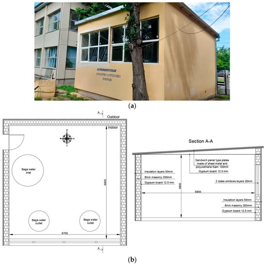
Figure 1.
The “ExperimentariumTM” building. Energy conversion and storage”: (a) The south facade of the building image; (b) Plan and section view of the building.
The building has an interior volume of 179 m3 and is an above-ground construction made of hollow brick, plated on the inside with 12.5 mm gypsum plasterboard on the inside and insulated on the outside with 5 cm polystyrene. The roof is made of prefabricated sandwich panel type plates made of sheet metal and polyurethane foam, on a single slope with an inclination of 3 degrees. On the south facade, there are four monocrystalline photovoltaic panels that will be supplemented up to a total installed power of 2.48 kW.
The heating system integrates a water–water heat pump (PC water–water 10 kW), fan coils (3 × 2.06 kW), and a photovoltaic system (monocrystalline photovoltaic panels) for the electricity supply of the proposed system. The water supply to the heat pump is generated from the Bega River through an underground channel with a length of 19 m using a centrifugal pump with variable speed to modulate the thermal load, with the power of 180 W.
The free cooling system integrates fan coil units (1 × 1.9 kW and 1 × 3.16 kW), and the electricity supply is from the same photovoltaic system. The water supply to the cooling system is generated from the same underground channel using a centrifugal pump with a variable speed, with the power of 80 W. The model of the hybrid system that describes the sequence of the work steps is presented in the form of a logic diagram in Figure 2.
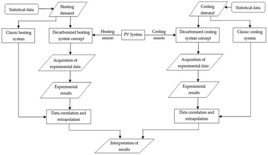
Figure 2.
Logic diagram—work stages.
The two research directions for the town of Timișoara, followed:
- ensuring the need for thermal energy for heating during the cold season. In the calendar year 2023, considered the reference year for the study, the supply of thermal energy was carried out in two stages: the beginning of the year—the period 1 January–2 May, and the end of the year—the period 1 October–31 December;
- ensuring the need for thermal energy for cooling during the hot season. For the study, the period of the hot season, for Timișoara, was considered as 1 June–30 September, during which the average daily temperature was above 25 °C.
As a rule, the period of the cold season, for Timișoara, is considered as 1 October–30 April, but based on the INMH (National Institute of Meteorology and Hydrology) forecast, three consecutive days of a minimum temperature lower than 10 °C or higher than 10 °C indicates the start or end of the thermal energy supply [22].
The installation of the two systems proposed for the decarbonization of space heating and cooling, respectively, and the data acquisition system was completed in February 2024, and the monitoring and data acquisition took place between 1 March and 10 June.
Thus, in the study presented in this article that considered the interval from 2 May to 31 May, related to the heating season and, respectively, 1 June to 30 June for the space cooling, to determine the characteristic parameters of the heating/cooling systems (heat pump, fan coils unit), the hypotheses were considered:
- -
- for the heating scenario:
- -
- the heat supply in the interior space was achieved with the heat pump operating in a water recirculation system circulated through the vaporizer to determine the progressive decrease in temperature. The heat pump operating characteristics were recorded and assimilated for the surface water temperatures specific to the cold season between 4 °C and 18.5 °C.
- -
- the evacuation of the produced heat (considered as the heat lost by the building during the cold season) was achieved through the operation of the cooling system with fan coil units through which water from the Bega River was circulated.
By operating in this configuration, the characteristics of the heat pump were experimentally determined, namely the variation of the coefficient (COP) depending on the temperature T1 of the water entering the heat pump (range 4–18.5 °C). The data obtained from the variation in the parameters recorded as a result of the system operation, in the previously described test mode, were extrapolated to calculate the available energy during the cold season of the surface water in the Bega River, considering the history of the meteorological data available for the water temperature in Bega.
- -
- for the cooling scenario:
- -
- during the hot season, the period from 1 June to 30 June was analyzed. During this interval, the proposed system operated at external temperatures that recorded values of a maximum of 37.8 °C, similar to the values recorded during July 2023 (maximum of 37 °C), which are representative values for the hot season in Timișoara.
The data acquisition system was made with two Io-Link modules for field applications with the EtherNet/IP interface. Each module used (type AL 1222) master-slave configuration equipped with 2 × 8 digital inputs (Io-Link) and a number of 8 digital outputs.
Each module was equipped with eight ports to which sensors were connected for measuring the operating parameters (flow rates and temperatures). Data acquisition was performed using the Moneo software Version 1.13 available on the Moneo IIoT platform, which made it possible to set the Io-link sensors online/offline and display the data acquired from the sensors in the field. To measure the temperature at different points of the process, Io-link TA 2115 temperature sensors and PT 1000 type sensors with a current output of 4–20 mA were used, with a response time of 3 s, a temperature range between −50 °C and +150 °C, and an accuracy of ±0.3 K. For the measurement/monitoring of the water flows, three ultrasonic sensors were used with the frequency of the end point in the range of 1–10 kHz and the type SU 8020 with a measurement range of 1–240 L/min, with a precision of ±1% of the measured value and +0.5% of the final value of the measuring range.
Data acquisition and reading were performed with a frequency of 20 readings/minute. The data are stored on a specially allocated data server in the laboratory and can be viewed graphically and exported as *.cvs files. A TP-link 4G router was installed for the remote system monitoring.
2.2. Local Climatic Conditions
2.2.1. Climatic Conditions of Timișoara
The town of Timișoara is located at the intersection of the parallel of 45°47′ north latitude, with the meridian of 21°17′ east longitude, and falls under a moderate continental temperate climate with some sub-Mediterranean influences (Adriatic variant) [18].
A map on which the position of the city of Timișoara has been marked is shown in Figure 3 [23], and the location detail of the building “ExperimentariumTM. Energy conversion and storage”, in relation to the Bega River, is shown in Figure 4 [24].
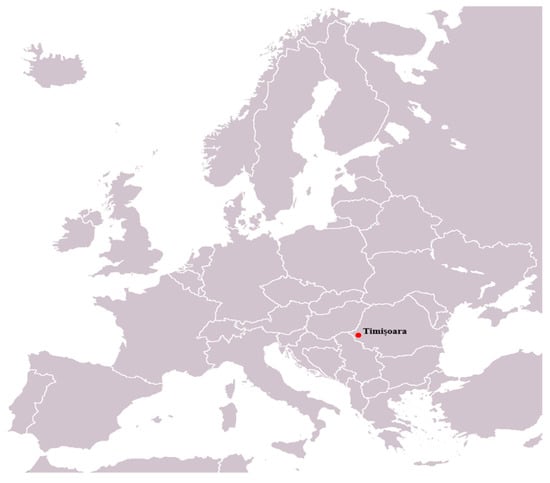
Figure 3.
Position of the Timișoara city on the regional map [19].
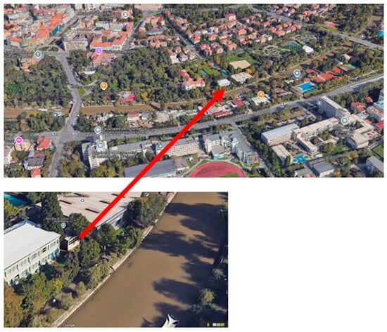
Figure 4.
The amplasament of the “ExperimentariumTM” building. Energy conversion and storage” relative to the Bega River [20].
Atmospheric processes are erratic and diverse. Winters are wet with intrusions of continental polar air masses from the east between September and February. The warm season presents periods of stifling heat generated by warm air masses from the Adriatic Sea and the Mediterranean Sea. Statistical data indicate a multiannual mean temperature of 10.6 °C [18].
For the study, meteorological data available in international databases [19] were used, with the help of which, for Timișoara, relative to the year 2023, the variations in temperature, relative humidity, wind speed, and mean sea level pressure were plotted, which are presented in Figure 5. For the year 2023, an average temperature of 13.4 °C (2.8 °C more than the statistical data), a maximum of 35.9 °C, and a minimum of 7.4 °C were recorded.
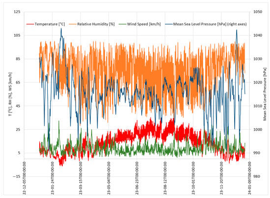
Figure 5.
Meteorological data.
2.2.2. Hydrogeological Conditions of the Bega River
The Bega River is the southernmost tributary of the Tisza that springs from the Poiana Ruscă Mountains and is channeled for navigation from Timișoara to its confluence over a distance of 115 km. One of the advantages of the Bega River is that it has a constant flow, being one of the two rivers in the Banat hydrographic space that does not dry up during the summer [18]. The multiannual average flow of the Bega River is taken from statistical data and is quantified at 16 m3/s [20].
Regarding the legislative framework on the taking over of water flows from surface water sources, it is specified in the Water Law that a use in installations with a small capacity of up to 0.2 L/s that are not returned is allowed, with the notification that if they don’t exceed 10 L/s and if they are returned, they do not influence the quality of the water resources [21]. For the operation of the proposed hybrid system for space heating, it is necessary to take a flow of 1 L/s and, respectively, 0.23 L/s for cooling; however, this water flow is not consumed and is fully returned to the Bega River through a circuit evacuation. Since the water taken from the Bega River circulates in the heating system in a closed circuit, it is not contaminated and thus the discharged water does not influence the quality of the water from the Bega River, being only thermally charged within the permitted limits of a maximum of 35 °C [21,25]. Therefore, the legislative framework in Romania is favorable to the installation of this type of system.
The water temperatures in the Bega River were measured during 2023 in the catchment channel using a PT 100 sensor and an acquisition system developed with an Arduino Uno board. The water temperature of the Bega River during the cold season is a minimum of 1 °C—measured in February, and a maximum of 18.3 °C—measured in May. The average temperature corresponding to the cold season is 9.2 °C. The water temperature of the Bega River during the warm season is a minimum of 18.5 °C—measured in February, and a maximum of 24.7 °C—measured in May. The average temperature corresponding to the hot season is 21.39 °C.
The variation in temperatures during the warm and cold seasons related to the year 2023 is presented in Figure 6.
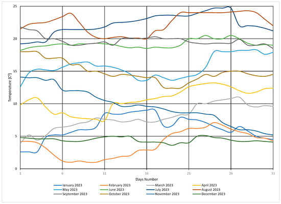
Figure 6.
Water temperature variation in the Bega River.
The thermal potential of the water in the Bega River was estimated to determine the available amount of thermal energy that can be taken without exceeding the permissible temperature limits for discharge into the outfall.
2.2.3. The Solar Potential for the Town of Timișoara
The amount of locally available solar energy is an important condition for sizing solar systems. The evaluation of the solar potential and the performances of the photovoltaic (PV) systems, for the town of Timișoara, was carried out with the help of the PV GIS program, which provides hourly, daily, or monthly information to obtain data on solar radiation and energy production. PV GIS uses the globally available database ERA5 [26].
The monthly energy output from the fixed-angle PV system and the monthly in-plane irradiation for the fixed-angle are presented in Figure 7 [26].
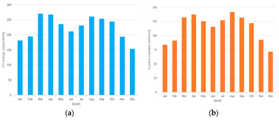
Figure 7.
Evaluation of solar photovoltaic potential: (a) Monthly energy output from the fix-angle PV system; (b) Monthly in-plane irradiation for the fixed-angle.
2.3. Decarbonization of the Heating System
2.3.1. Calculation of the Heating Demand
The heat requirement was determined using the Radia 3 calculation program [27,28] based on the norms and standards in force in Romania [29,30,31] to ensure thermal comfort in the building. The calculated external temperature corresponds to climate zone II (−12 °C). The internal calculation parameters (temperature and relative humidity of the indoor air) were considered depending on the destination of the building, the desired ambience category (III–moderately acceptable level, recommended in existing buildings) and the indoor air quality category (IDA 3) [31]. The minimum corrected thermal resistances R’min in m2K/W and the corrected thermal transmittances U’max in W/m2K for the analyzed building are presented in Table 1.

Table 1.
Thermal resistances and thermal transmittances corrected for the envelope elements of the analyzed building.
The calculated indoor temperature for the laboratory spaces is 18 °C [29]. The calculations resulted in a demand of 5.99 kW for space heating.
According to the ranked curve (Figure 8), for 5127 h of operation, the thermal energy consumption related to the year 2023 was 15,862.1 kWh.
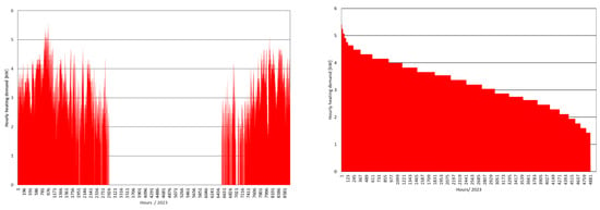
Figure 8.
Annual duration curve for space heating demand—2023. The graph on the (left) shows the distribution of the required heating during the hours of a year. In the graph on the (right), the annual hourly values of the heating requirement are presented, sorted in descending order.
2.3.2. Presentation of the Old Heating System
Until 2023, the supply of thermal energy for space heating was from the urban centralized system. The thermal energy in the centralized system of the town of Timișoara was produced from burning in boilers a mix of fossil fuels: lignite and natural gas.
The thermal agent distribution system in the building consisted of a two-pipe heating system of non-insulated steel pipes. Heat transfer in the building’s spaces was achieved with heating elements, equipped with two rows of steel convective panels with thermostatic heads for the room temperature regulation. The piping system was hydraulically balanced using control valves installed on the return side.
For the year 2023, the energy requirement of 15,862.1 kWh was provided by the district heating local centralized system.
The conversion factors of primary energy into equivalent CO2 emissions for the fuels used are presented in Table 2 [32].

Table 2.
Conversion factors of primary energy into equivalent CO2 emissions [32].
The CO2 emission factor for the thermal energy mix used (90% lignite and 10% natural gas) was considered to be 0.4342 kgCO2/kWh, a factor that also includes losses on the transmission network from the source to the consumer (approximately 35%), resulting in a total of emissions of CO2 in the atmosphere of 6887.28 kg/year.
2.3.3. Presentation of the Proposed Heating System
In order to decarbonize the classic heating system, the development of the proposed heating system took into account the identification and rational use of locally available renewable energy sources. In this context, the sustainable use of the mix of thermal energy from surface waters and electricity obtained using photovoltaic panels has been established as the optimal solution. The hydride water–water heat pump system coupled with a photovoltaic system was developed to ensure the heating needs during the cold season. To highlight the impact of the new system on the CO2 footprint of the heating system, the proposed hybrid system was equipped with a system for acquiring and storing functional parameters. The operation scheme and the experimental stand are shown in Figure 9.
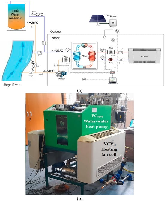
Figure 9.
Functional diagram of the decarbonized heating system: (a) functional diagram of the installation; (b) the experimental stand. To—Outside air temperature; Ti—Indoor air temperature; T1—Evaporator inlet temperature; T2—Evaporator outlet temperature; T3—Condenser outlet temperature; T4—Condenser inlet temperature; Hi—Indoor air humidity; FM1—Flowmeter water source; FM2—Heating water flow meter; PWBH—Bega water circulation pump; PHW—Heating circulation pump; VCVH—Heating fan coil; PCWW—Water–water heat pump.
The proposed heating system has as its energy source a water–water heat pump (PCww) of 10 kW thermal power. The energy source in the vaporizer circuit is the water taken from the Bega River by means of a variable speed centrifugal pump PWBH. On this circuit are placed two temperature sensors, T1 for the temperature of the water entering the evaporator and T2 for the temperature of the water leaving the evaporator. Also, an FM1 flowmeter is mounted on the inlet circuit for monitoring/counting the flow of the water circulated through the vaporizer. Since the operation of the PCWW in the heating mode takes energy from the fluid circulating through the evaporator heat exchanger, the temperature T2 will be lower than the temperature T1. The data provided by T1, T2, and FM1 are used to calculate the thermal energy taken from the Bega River. The thermal energy produced with the help of PCWW is given to the heat agent that circulates through the condenser circuit. The circulation of the heat agent through the heating system with fan coils VCVH is ensured by the circulation pump PHW. Two temperature sensors are placed on this circuit, T3 for the temperature of the water leaving the condenser and T4 for the temperature of the water entering the condenser. Also, the FM2 flowmeter is mounted on this circuit for monitoring/counting the flow of thermal agent circulated through the heating system. The data provided by T3, T4, and FM2 are used to calculate the thermal energy given to the interior space.
For the partial supply of electricity to the consumers of the heating system, the possibility of supplementing the electricity production capacity by placing four more panels was analyzed, up to a total installed power of 2.48 kW, which is limited by the space available for the placement of the photovoltaic panels.
The data acquisition system also monitors and stores data on the indoor temperature through the Ti sensor, the outdoor temperature through the To sensor, and the indoor humidity through the Hi sensor.
The proposed heating system must ensure an annual energy requirement of 15,862.1 kWh.
2.4. Decarbonization of the Cooling System
2.4.1. Calculation of the Cooling Demand
The calculation of the cooling requirement was determined using the CoolPack Version 1.49 program [33] based on the norms and standards in force for Romania [28,30,31], to ensure thermal comfort in the building. The internal comfort conditions taken into account for the calculation are those presented in the subchapter “Calculation of the heating requirement” [31]. For Timișoara, the design standard [31] specifies the following values as the calculation data for air conditioning systems (warm season): 36.4 °C for the temperature and 25% for the humidity. For cooling, an internal temperature of 25 °C was considered, which is in the range of 22–27 °C accepted for clo 0.5. The maximum outside temperature considered for the calculation was 40 °C. For the town of Timișoara, a requirement of 911 h of operation of the outdoor temperature above 25 °C was determined. The calculations resulted in a cooling requirement of 2.03 kW.
2.4.2. Presentation of the Existing Cooling System
A Yamato Optimum YW09T2 air conditioner with a power of 2.6 kW (9000 BTU) and a nominal hourly electricity consumption of 825 W was used to cool the space. According to the ranked curve (Figure 10), for 911 h of operation, a cooling energy requirement of 1098.66 kWh was recorded. In the conditions in which this requirement was ensured with the cooling equipment with a COP of 3.15, an electrical energy requirement for cooling of 348.78 kWh resulted. Reported to the year 2023, the production of electricity in Romania was provided from a mix of energy sources; for the cooling system, a quantity of CO2 emissions of 92.38 kg/year was calculated [33].
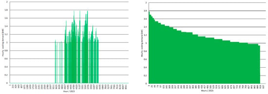
Figure 10.
Annual duration curve for space cooling demand—2023. The graph on the (left) shows the distribution of the required cooling during the hours of a year. In the graph on the (right), the annual hourly values of the cooling requirement are presented, sorted in descending order.
2.4.3. Presentation of the Proposed Cooling System
In order to decarbonize the classic cooling system, the identification and rational use of locally available renewable energy sources were considered. In this context, the sustainable use of the mix of thermal energy from the surface water and the electricity obtained with the photovoltaic panels has been established as the optimal solution. The hydride fan coil system and photovoltaic system was developed to ensure the cooling needs during the hot season. To highlight the impact of the new system on the CO2 footprint of the cooling system, the proposed hybrid system was equipped with the operating system and the storage of functional parameters. The operation scheme and the experimental stand are shown in Figure 11.
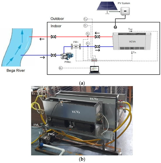
Figure 11.
Functional diagram of the decarbonized cooling system: (a) functional diagram of the installation; (b) the experimental stand. To—Outside air temperature; Ti—Indoor air temperature; T1—Fan coil supply temperature; T2—Fan coil return temperature; Tin—Fan coil inlet air temperature; Tout—Fan coil outlet air temperature; Hi—Indoor air humidity; FM1—Flowmeter water source; PWBC—Bega water circulation pump; VCVR—Cooling fan coil.
The proposed cooling system is based on the concept of free cooling. The source of cold energy is water from the Bega River, which is circulated using the variable speed centrifugal pump PWBC. Two temperature sensors, T1 for the water inlet temperature in the VCVR fan coil units, and T2 for the water outlet temperature in the VCVR fan coil units, are located on this circuit. The air temperature at the entrance of the VCVR fan coils is monitored by the Tin temperature sensor, and at the exit of the VCVR fan coils, by the Tout sensor. Also, an FM1 flow meter is mounted on the input circuit for monitoring/counting the flow of water circulated through the fan coil units. Since the operation of the fan coil units in the cooling mode takes energy from the indoor air, the temperature T2 will be higher than the temperature T1. The data provided by T1, T2, and FM1 are used to calculate the thermal energy discharged from the cooled space. The thermal energy is discharged towards the Bega River without exceeding the permitted limits for the discharge of the water into the outfalls.
The cooling system is supplied with electricity from the proposed photovoltaic system. The data acquisition system also monitors and stores data on the indoor temperature through the Ti sensor, the outdoor temperature through the To sensor, and the indoor humidity through the Hi sensor. The general plan with the location, in site, of the sensors for monitoring the heating and cooling systems is shown in Figure 12.
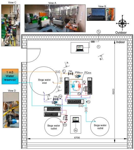
Figure 12.
The general plan with the location of equipment and sensors.
3. Results and Discussions
In the results section, the two systems are treated separately: heating and cooling. First, the results obtained based on the parameters recorded by the operation of the heating system during the period 2 May 2024–31 May 2024 are presented. Second, the results obtained based on the parameters recorded by the operation of the cooling system during the period 1 June 2024–10 June 2024 are presented.
3.1. Decarbonized Heating System—Experimentally Tested
Given that the new experimental heating installation became functional at the end of the heating season, in order to determine the characteristic parameters of the equipment (heat pump, fan coils), a water recirculation system taken from the Bega River was made to determine the variation in the coefficient (COP) depending on the temperature T1 of the water entering the heat pump (range 4–18.5 °C).
The calculation relationships that were the basis for determining the COP performance coefficient of the water–water heat pump were [34,35]:
where:
QHC—energy produced by the water–water heat pump, in kW;
QHR—energy extracted by the heat pump from the surface water source (Bega river), in kW;
Ee—electricity, in kW.
The energy produced by the water–water heat pump QHC was calculated using the relationship (2) and the energy extracted by the heat pump from the surface water source, with the relationship (3):
where:
c—the specific heat of water;
FM2—the water flow rate in the heating circuit;
t3 and t4—the outlet and inlet temperatures of the condenser in the heat pump, respectively;
FM1—the water flow rate from the river;
t1—the river water temperature in the inlet in the heat pump vaporizator;
t2—the water temperature in the outlet from the heat pump vaporizator (returned water to the river).
The variation in the parameters recorded as a result of operation, in the previously described test mode, is presented in Figure 13.
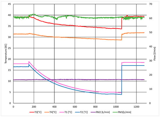
Figure 13.
The variation in the data recorded with the system operating in the heating mode.
Based on these data, the COP performance coefficients were calculated, the variation in which depends on the water inlet temperature in the heat pump (range 4–18.5 °C), shown in Figure 14.
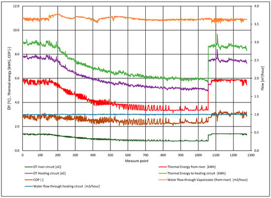
Figure 14.
Variation in the heat pump COP coefficient.
3.2. Analysis of the Results Obtained through the Operation of the Decarbonized Heating System
Figure 13 shows the variation in the data recorded during the test period (1300 measurement points) for the main heating equipment (heat pump). Thus, keeping the fluid flow through the evaporator and the condenser relatively constant and gradually changing the temperature entering the evaporator T1, the variation in the temperature leaving the evaporator T2, the variation in the temperature of the thermal agent at the exit from the condenser T3, and the temperature entering the condenser T4 were monitored. During the monitoring period, the complete evacuation of the thermal energy produced by the heat pump was ensured so that it worked at maximum capacity. It was observed that the variation in the temperature of the water at the entrance of the heat pump within a range of 14.2 °C corresponded to a variation of 6.2 °C in the temperature of the thermal agent at the exit of the heat pump. The lower temperature difference on the side of the thermal agent was compensated by a higher consumption of electricity.
Figure 14 shows the variation in the thermal power provided by the heat pump with a minimum of 5.7 kW and a maximum of 9.6 kW by extracting thermal energy from the water source within the limits of 3.1 kWh and 5.9 kWh. These powers were calculated based on the temperature differences T3–T4 and T1–T2, respectively.
The variation in the water flow through the evaporator was also observed, determined by the change in the operating parameters of the circulation pump when changing the density of the fluid circulated in a temperature range of 14.2 °C. This type of variation was less obvious in the case of the flow of a thermal agent because the temperature T4 of its entry into the circulation pump varied only by 3.4 °C during the tests.
The graph also shows the variation in the COP performance factor and shows the operation of the heat pump with a maximum performance of 3.34 and a minimum performance of 2.07.
The thermal potential of the water in the Bega River was estimated both for the heating season and the cooling season as the available amount of thermal energy that can be taken from the river, considering both the minimum water temperature available for the operation of the heat pump and the maximum limit of the temperature that can be discharged into the emissary without exceeding the limits allowed by the legislation in force.
Thus, for heating, considering the required thermal energy (15,862 kWh) to cover the heat demand calculated using the local climatological conditions of the site and considering the seasonal performance coefficient (SCOP) of the water–water heat pump, a water requirement of 5233.64 m3/year was determined. The thermal potential of the water flow taken from the Bega River was 9124.3 kWh/year, the difference of 6737.9 kWh being provided by electricity. Considering the local production of electricity with PV during the cold season of 1503.8 kWh, this results in an electricity requirement from the SEN of 5234.1 kWh. The amount of CO2 emitted by the tested system operating in the heating mode, for a period of 5127 h/year, was 1387.04 kg/year without taking into account the influence of the photovoltaic system.
Compared with the existing system (6887.28 kg/year), there was a decrease in CO2 emissions by 5500.24 kg/year, which represents a reduction of 79.86%.
3.3. Decarbonized Cooling System—Experimentally Tested
Considering that the new experimental cooling installation became functional from 31 May 2024, to carry out the study, the characteristic operating parameters of the free cooling system were monitored during 6–10 June. The variation in the parameters recorded after operation is shown in Figure 15.
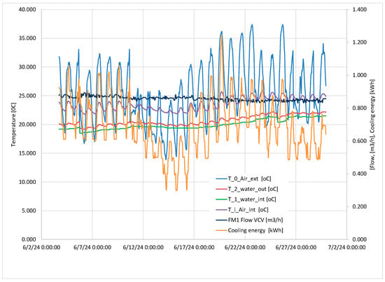
Figure 15.
The variation in the data recorded with the system operating in the cooling mode.
3.4. Analysis of the Results Obtained through the Operation of the Decarbonized Cooling System
Figure 15 shows the variation in the data recorded during the 6–10 June test period for the free cooling equipment with fan coil units. Thus, it can be seen that with a day/night variation in the outside temperature between 33.3 °C and 16.67 °C, the cooling system managed to keep the inside space at an internal temperature between 21.76 °C and 24.5 °C, operating with an internal temperature difference—cooling water temperature of 4 °C. From this mode of operation, we can draw the conclusion that even in the situation where the external temperature will reach a maximum value of 35.9 °C, a maximum cooling water temperature of 24.7 °C will ensure an internal temperature in the range of 22–27 °C.
For cooling, considering the required thermal energy (1098.66 kWh) to cover the cold demand calculated in the local climatological conditions of the site, a water requirement of 945.27 m3/year was determined. In order to ensure the electrical energy required for the cooling water circulation pump and the fan coil motors, an electrical energy requirement of 200.42 kWh was calculated, which can be fully covered by the local electricity production (1193.1 kWh).
The amount of CO2 emitted by the tested system operating in the cooling mode, for a period of 911 h/year, is 53.11 kg/year, without taking into account the influence of the photovoltaic system.
The installation of the photovoltaic system will ensure an electricity production during the warm season of 1193.1 kWh. This energy ensures that the electricity consumption of the proposed cooling systems is 200.42 kWh. The Figure 16 presents a comparative analysis of the two analyzed systems from the point of view of the annual reduction in energy consumption and CO2 emissions. These data are highlighted in the conclusions.
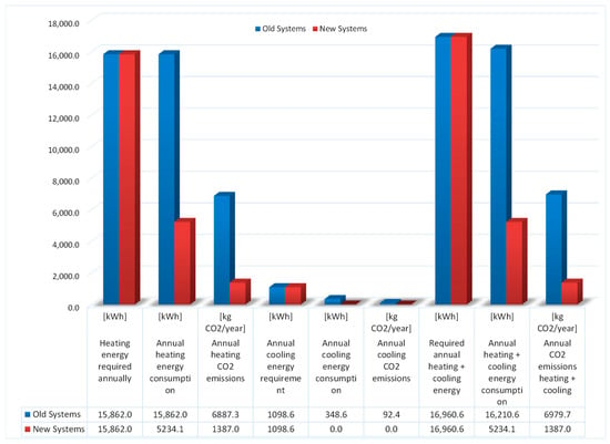
Figure 16.
A comparative analysis of the two analyzed systems from the point of view of the annual reduction in energy consumption and CO2 emissions.
Recent research addressing the modeling of hybrid heating and cooling systems with heat pumps coupled with photovoltaic systems shows that by coupling them, the energy efficiency of the hybrid system increases by up to 25% compared with heat pump-only systems [34,35,36].
4. Conclusions
The novelty of this research consists in the realization of two experimental systems, one for the rapid evaluation of the performance of the water–water heat pump heating system and one for the evaluation of the operating behavior of a cooling system with fan coil units.
The extrapolation of the results obtained following the operation of the two systems was realized in order to forecast the energy potential and the capacity of the surface water to contribute to the decarbonization of the existing heating and cooling systems in buildings.
Starting with the heat and cold demand, the climatic characteristics of the area (temperatures, radiation, humidity), and the hydrological characteristics of the surface water source (flow, temperature), a hybrid system model was established and implemented for the heating and cooling of a building (didactic laboratory) located in Timișoara near the Bega River (surface water course).
The annual energy consumption and CO2 emissions were compared between the old system with which the building was equipped (supply with thermal energy from the district heating system and cooling with an air conditioner unit) and the proposed hybrid system (decarbonized): a heating system with a water–water heat pump and a cooling system with fan coil units.
The study is relevant by presenting its own approach methodology that can be used in the further development of decarbonized heating and cooling systems in buildings located near surface water sources. Also, the obtained results can be used as a basis of comparison for similar experimental studies.
From the comparative analysis of the results obtained through the operation of the two heating and cooling systems, in the classic and proposed versions, it follows that for the same heating and cooling requirements, respectively, the proposed systems are more efficient both in terms of energy consumption and reducing CO2 emissions.
The proposed hybrid system for heating recorded a decrease in energy consumption of 10,627.9 kWh and a reduction in CO2 pollutant emissions of 5500.24 kg/year.
Regarding the operation of the hybrid system proposed for cooling, there was a decrease in energy consumption of 348.6 kWh and a reduction in CO2 pollutant emissions of 92.4 kg/year.
In conclusion, for the analyzed building, an annual energy consumption reduction of 10,976.5 kWh and a total decarbonization of the heating and cooling processes of 5592.6 kg/year were obtained.
The major advantage of using surface water to cover the energy needs of buildings is that they are relatively easily available without expensive investments in drilling and without a negative impact on the environment and groundwater.
As one of the major objectives of building energy efficiency measures is decarbonization, it is obvious that the use of any technologies that lead to substantial reductions in carbon emissions should be encouraged.
Author Contributions
Conceptualization, A.T.; methodology, A.T., D.M., D.T. and D.B.; software, D.T.; validation, A.T., D.M., D.T. and D.B.; investigation, A.T., D.M., D.T. and D.B.; writing—original draft preparation, D.M. and D.T.; writing—review and editing, A.T. and D.B. All authors have read and agreed to the published version of the manuscript.
Funding
This research received no external funding.
Data Availability Statement
The original contributions presented in the study are included in the article, further inquiries can be directed to the corresponding authors.
Conflicts of Interest
The authors declare no conflicts of interest.
References
- Nagaj, R.; Gajdzik, B.; Wolniak, R.; Wieslaw, W.G. The Impact of Deep Decarbonization Policy on the Level of Greenhouse Gas Emissions in the European Union. Energies 2024, 17, 1245. [Google Scholar] [CrossRef]
- Garimella, S.; Lockyear, K.; Pharis, D.; El Chawa, O.; Hughes, M.T.; Kini, G. Realistic pathways to decarbonization of building energy systems. Joule 2022, 6, 956–971. [Google Scholar] [CrossRef]
- Muntean, D.; Tokar, D.; Tokar, A.; Daniel Bisorca, D.; Dorca, A. Solutions for the Energy Efficiency of Buildings Located Near Watercourses through SRE Integration. Case Study. Rom. J. Civ. Eng. 2024; accepted. [Google Scholar]
- Zimakov, A.V. European Strategic Approaches to Heating Decarbonisation. Mirovaia Ekon. I Mezhdunarodnye Otnos. 2019, 63, 39–46. [Google Scholar]
- Xu, S.; Yan, C.; Jin, C. Design Optimization of Hybrid Renewable Energy Systems for Sustainable Building Development based on Energy-Hub. Energy Procedia 2019, 158, 1015–1020. [Google Scholar] [CrossRef]
- Zheng, J.; Chen, Z.; Zhang, T.; Huang, X.; Wang, X. Regional sustainable and renewable energy development in China: A comprehensive assessment and influencing factors. Energy Rep. 2023, 9, 76–80. [Google Scholar] [CrossRef]
- Balasubramanian, S.; Balachandra, P. Effectiveness of demand response in achieving supply-demand matching in a renewables dominated electricity system: A modelling approach. Renew. Sustain. Energy Rev. 2021, 147, 111245. [Google Scholar] [CrossRef]
- Al-Ghussain, L.; Abubaker, A.M.; Ahmad, A.D. Superposition of Renewable-Energy Supply from Multiple Sites Maximizes Demand-Matching: Towards 100% Renewable Grids in 2050. Appl. Energy 2021, 284, 116402. [Google Scholar] [CrossRef]
- Tong, D.; Farnham, D.J.; Duan, L.; Zhang, Q.; Lewis, N.S.; Caldeira, K.; Davis, S.J. Geophysical constraints on the reliability of solar and wind power worldwide. Nat. Commun. 2021, 12, 6146. [Google Scholar] [CrossRef] [PubMed]
- Heating and Cooling Decarbonisation Must Be a Priority to Achieve a 90% GHG Emissions Reduction by 2040. Available online: https://www.efiees.eu/wp-content/uploads/2024/03/Statement-on-2040-climate-Target.pdf (accessed on 3 June 2024).
- Zhang, S.; Ocłoń, P.; Klemeš, J.J.; Michorczyk, P.; Pielichowska, K.; Pielichowski, K. Renewable energy systems for building heating, cooling and electricity production with thermal energy storage. Renew. Sustain. Energy Rev. 2022, 165, 112560. [Google Scholar] [CrossRef]
- Canale, L.; Di Fazio, A.R.; Russo, M.; Frattolillo, A.; Dell’Isola, M. An Overview on Functional Integration of Hybrid Renewable Energy Systems in Multi-Energy Buildings. Energies 2021, 14, 1078. [Google Scholar] [CrossRef]
- Noro, M.; Lazzarin, R. PVT and ETC Coupling for Annual Heating and Cooling by Absorption Heat Pumps. Sustainability 2020, 12, 7042. [Google Scholar] [CrossRef]
- Perrella, S.; Bisegna, F.; Bevilacqua, P.; Cirone, D.; Bruno, R. Solar-Assisted Heat Pump with Electric and Thermal Storage: The Role of Appropriate Control Strategies for the Exploitation of the Solar Source. Buildings 2024, 14, 296. [Google Scholar] [CrossRef]
- Kalair, A.; Abas, N.; Saleem, M.S.; Kalair, A.R.; Khan, N. Role of energy storage systems in energy transition from fossil fuels to renewables. Energy Storage 2020, 3, e135. [Google Scholar] [CrossRef]
- Carnie, J.T.; Hardalupas, Y.; Sergis, A. Decarbonising building heating and cooling: Designing a novel, inter-seasonal latent heat storage system. Renew. Sustain. Energy Rev. 2024, 189, 113897. [Google Scholar] [CrossRef]
- Bandyopadhyaya, B.; Banerjee, M. Decarbonization of cooling of buildings. Sol. Compass 2022, 2, 100025. [Google Scholar] [CrossRef]
- Strategia Integrată de Dezvoltare Urbană 2015–2020 Polul de Creştere Timişoara. Available online: https://arhiva.primariatm.ro/file_uploads/PID_2016/Cap_1_1_03_2016.pdf (accessed on 7 June 2024).
- Meteoblue—Historical Weather Data. Available online: https://www.meteoblue.com/en/weather/archive/export (accessed on 5 June 2024).
- Planul de Management Actualizat al Spațiului Hydrogeografic Bega. Available online: https://www.mmediu.ro/app/webroot/uploads/files/PMSH_Actualizat_Text_ABABANAT.pdf (accessed on 7 June 2024).
- Legea Apelor nr. 107/1996. Available online: https://lege5.ro/Gratuit/ge3demru/legea-apelor-nr-107-1996 (accessed on 7 June 2024).
- Regulament Privind Începerea şi Încetarea Furnizării Încălzirii. Available online: https://www.colterm.ro/9-de-actualitate/80-regulament-privind-inceperea-si-incetarea-furnizarii-incalzirii (accessed on 7 June 2024).
- Localizarea Municipiului Timișoara (România) în Europa. Available online: https://ro.wikipedia.org/wiki/Timișoara#/media/Fișier:Timisoara_in_Europe.png (accessed on 1 July 2024).
- Google Maps. Available online: https://www.google.com/maps/@45.7483305,21.229173,55a,35y,35.48h,56.4t/data=!3m1!1e3?authuser=0&entry=ttu (accessed on 8 July 2024).
- Normativ NTPA-001/2002 din 28 Februarie 2002 (*Actualizat*) Privind Stabilirea Limitelor de Încărcare cu Poluanti a Apelor Uzate Industriale şi Urbane la Evacuarea în Receptorii Naturali. Available online: https://legislatie.just.ro/Public/DetaliiDocumentAfis/98311 (accessed on 3 June 2024).
- PVGIS-Photovoltaic Georgaphical Information System. Available online: https://pvgis.com/pvgis (accessed on 7 June 2024).
- Calcul Termic—Radia 3. Available online: https://docs.google.com/spreadsheets/d/1VkAHPZFsoI0TlhEFulK70NtlWM5YWfEU/edit#gid=1044508031 (accessed on 5 June 2024).
- Ministerul Dezvoltării, Lucrărilor Publice și Administrației. Metodologie de Calcul al Performanței Energetice a Clădirilor, Indicativ Mc 001-2022, Partea I, Nr. 46 bis/17.I.2023; Bucharest, Romania, 2023.
- Ministerul Dezvoltării, Lucrărilor Publice și Administrației. Normativ Pentru Proiectarea, Executarea și Exploatarea Instalațiilor de Încălzire I 13-2022, Partea I, Nr. 108 bis/8.II.2023; Bucharest, Romania, 2023.
- Technical Committee ISO/TC 163. Energy Performance of Buildings—Energy Needs for Heating and Cooling, Internal Temperatures and Sensible and Latent Heat Loads—Part 1: Calculation Procedures; International Organization for Standardization: Geneva, Switzerland, 2017. [Google Scholar]
- Ministerul Dezvoltării, Lucrărilor Publice și Administrației. Normativ Pentru Proiectarea, Executarea și Exploatarea Instalațiilor de Ventilare și Climatizare, Indicativ I5-2022, Partea I, Nr. 108 bis/8.II.2023; Bucharest, Romania, 2023.
- Ministerul Mediului, Apelor și Pădurilor. Ordin nr. 2.057 din 16 Noiembrie 2020 Pentru Aprobarea Ghidului de Finanțare a Programului Privind Creșterea Eficienței Energetice și Gestionarea Inteligentă a Energiei în Clădirile Publice, nr. 1129 din 24 noiembrie; Bucharest, Romania, 2020.
- CoolPack. Available online: https://www.ipu.dk/products/coolpack/ (accessed on 5 June 2024).
- Qu, M.; Chen, J.; Nie, L.; Li, F.; Yu, Q.; Wang, T. Experimental study on the operating characteristics of a novel photovoltaic/thermal integrated dual-source heat pump water heating system. Appl. Therm. Eng. 2016, 94, 819–826. [Google Scholar] [CrossRef]
- Choi, H.U.; Kim, Y.B.; Son, C.H.; Yoon, J.I.; Choi, K.H. Experimental study on the performance of heat pump water heating system coupled with air type PV/T collector. Appl. Therm. Eng. 2020, 178, 115427. [Google Scholar] [CrossRef]
- Emmi, G.; Zarrella, A.; De Carli, M. A heat pump coupled with photovoltaic thermal hybrid solar collectors: A case study of a multi-source energy system Emmi. Energy Convers. Manag. 2017, 151, 386–399. [Google Scholar] [CrossRef]
Disclaimer/Publisher’s Note: The statements, opinions and data contained in all publications are solely those of the individual author(s) and contributor(s) and not of MDPI and/or the editor(s). MDPI and/or the editor(s) disclaim responsibility for any injury to people or property resulting from any ideas, methods, instructions or products referred to in the content. |
© 2024 by the authors. Licensee MDPI, Basel, Switzerland. This article is an open access article distributed under the terms and conditions of the Creative Commons Attribution (CC BY) license (https://creativecommons.org/licenses/by/4.0/).