Article

The Effect of Hydrogen as a Coolant on the Characteristics of Humidification-Dehumidification Desalination Systems

by
Antar M. M. Abdala
1,2,*,
Fifi N. M. Elwekeel
3 and
Rodolfo Taccani
2
1
Faculty of Engineering, Helwan University, Mataria, Cairo 11718, Egypt
2
Department of Engineering and Architecture, University of Trieste, 34127 Trieste, Italy
3
Faculty of Industrial Education, Helwan University, Cairo 11813, Egypt
*
Author to whom correspondence should be addressed.
Energies 2024, 17(14), 3593; https://doi.org/10.3390/en17143593
Submission received: 17 May 2024 / Revised: 25 June 2024 / Accepted: 27 June 2024 / Published: 22 July 2024
(This article belongs to the Section J: Thermal Management)

Abstract

:
The air humidification-dehumidification (HDH) technique for water desalination can be useful in many water production applications. Researchers from all around the world have examined various implementations of this technology to improve it. The present research investigates the effect of three dehumidifier coolants on the system. These coolants include water, helium, and hydrogen. The impact of these coolants on the parameters of the humidification-dehumidification desalination system will be discussed. The investigation’s parameters are tested at various mass ratios, air flow rates, and air outlet heaters. The results show that when hydrogen is employed as a dehumidifier coolant, the gained output ratio (GOR) achieves its peak of 6.37 in the considered mass ratio range of 2.1 to 3. On the other hand, when hydrogen is utilized as a dehumidifier coolant, the system produces the maximum entropy, with the dehumidifier contributing the most. When the mass ratio changes from 2 to 3, the average entropy generation for the system using hydrogen in the dehumidifier increases by 3.8 and 2.9 times, respectively, compared to the average entropy generation for the system using water and helium. However, when hydrogen is used as a dehumidifier coolant, safety concerns must be addressed, as well as the size and cost of heat exchangers in comparison to water.

1. Introduction

In many parts of the world, freshwater is becoming increasingly scarce. Population growth promotes an increase in freshwater demand, particularly in pressured locations. Mankind is facing a water availability crisis, with demand estimated to exceed supply by 40% by 2030 [1]. As a result, water purification measures, together with conservation efforts, are required in areas where natural drinkable water resources are depleted [2]. Desalination processes include mechanical, electrical, and thermal methods [3]. The most widely utilized desalination technologies are reverse osmosis (RO) and thermal processes including multi-stage flash (MSF) and multi-effect desalination (MED) [4]. These technologies are particularly effective for water desalination. However, they cannot be used in small-scale units because of high maintenance expenses. Other water desalination options may be considered when technical and financial resources are limited. The humidification-dehumidification (HDH) desalination system is eco-friendly and promising for small-scale applications. HDH systems can be divided into two broad categories [5]. First, the type of energy source employed (solar, thermal, geothermal, etc.) is considered. The second classification is based on how the HDH cycles are built. The closed-air open-water (CAOW) form [6] circulates, humidifies, and dehumidifies air in a closed loop, in contrast to a closed-water open-air (CWOA) cycle [7], which heats, humidifies, and partially dehumidifies air.
Much research has recommended a humidification-dehumidification desalination system powered by renewable energy. Li et al. [8] investigated and presented a small-scale solar HDH system based on glass evacuated tube solar air heaters. Yıldırım and Solmus [9] analyzed the performance of an HDH water desalination system powered by solar air and water heaters under various design and operational conditions. Shatat et al. [10] conducted theoretical research on a small-scale HDH desalination plant equipped with an evacuated tube solar collector.
Kumar et al. [11] created a thermal model to estimate the performance of a single slope of solar still integrated with an evacuated tube collector in India’s climate. Liu et al. [12] reported thermal and economic evaluations for a water desalination system that used evacuated tube solar collectors. Al-Sulaiman et al. [13] presented an analysis study to assess the performance of an HDH system combined with a parabolic trough solar collector. El-Minshawy [14] performed simulation modelling to evaluate the performance of a seawater HDH water desalination system powered by a parabolic trough solar collector. The model was constructed using a comparative study to show the impact of the various operating conditions on system performance and water output.
Dayem and Fatouh [15] conducted theoretical and practical studies on various HDH solar-assisted water desalination systems to provide the most efficient system. Three systems were proposed and compared under the climatological conditions of Cairo. Gabrielli et al. [16] proposed an HDH system combined with photovoltaic-thermal (PVT) solar modules for the simultaneous generation of clean water and power. Muthusamy and Srithar [17] conducted energetic and exergetic evaluations on various types of packing materials used in humidifier units. The exergy analysis of these experiments revealed that the modified HDH desalination system enhanced productivity by 45% while also improving energy and exergy efficiency by 44% and 38%, respectively. Improving humidification and dehumidification efficiency leads to better thermodynamics performance and lower water production costs. This can be enhanced by various humidifier or dehumidifier packing types [18,19].
Elsafi [20] presented a mathematical model of the HDH desalination system, which includes concentrated photovoltaic-thermal collectors. An exergy-costing module was used to determine the system’s product cost in steady-state conditions. Alrbai [21] investigated a novel humidification-dehumidification (HDH) water desalination system integrated with fogging nozzles. They demonstrated a positive impact on the performance of the desalination process by lowering exergy destruction.
Garg et al. [22] prepared a heat and mass transfer model for a closed-air open-water (CAOW) and water-heated type HDH cycle equipped with a counter-flow packed-bed cooling tower for the humidification of air, and a finned-tube heat exchanger for dehumidification. Their model was used to determine the optimal humidifier and dehumidifier sizes based on the gained output and recovery ratios. Saha et al. tested the cross-flow and direct contact counter-flow packed-bed dehumidifiers [23]. The cross-flow design can thus be employed efficiently in place of a counter-flow direct contact packed-bed dehumidifier.
The dehumidifier was a strip-finned helical coil with cellulose paper used as a packing pad. This system, with the new dehumidifier, had higher productivity and performance than other systems, and increasing cooling pad thickness reduced production costs per kilogram of fresh water [24]. Hu et al. [25] examined the best model for a direct contact dehumidifier that used spherical PCM components as a packing medium. They investigated how condenser geometrical aspect ratio, packing size, air-to-water mass flow rate ratio, PCM thermal characteristics, and various packing media types affected system performance. The difference between the suggested model and the experimental data was less than 3%. Tan et al. [26] confirmed the experimental results using a model of a direct contact cross-flow packed-bed dehumidifier, and the variance was less than 10%.
The effects of seawater spraying temperature, quantity, and air volume flow rate on freshwater production rate and gain output ratio were observed in a four-stage cross-flow humidification and dehumidification system equipped with direct contact dehumidifiers [27]. Water per unit volume reached 34.1 kg/(m3 h), which was higher than previous studies; additionally, the device’s payback period was approximately 2.4 years. Waste energy and solar energy are both used to power humidification-dehumidification (HDH) desalination systems [28,29]. The cost of heat and mass transfer areas increases from $470.81 to $701.46 when the dry air mass flow rate is increased from 0.1 kg/s to 0.5 kg/s using waste energy.
Capocelli et al. [30,31] conducted a thermodynamic analysis of the humidification-dehumidification-adsorption (HDHA) desalination process. The gained output ratio grew to ten as the number of air extractions increased to three.
The literature cited above focuses on the design of the dehumidifier or the kind of flow and packing bed. No study was found that systematically aimed to increase and/or optimize HDH cycle performance by modifying the dehumidifier coolant. As a result, the aim of this research is to investigate the thermodynamic performance of the HDH cycle with proposed new dehumidifier coolants, as well as the implications of these coolants on HDH cycle performance. Also investigated are the effects of mass ratio, heater outlet air temperature, and air flow rate on HDH cycle performance. The fluids used in this investigation were chosen based on their thermodynamic properties, as shown in Table 1. The heat transfer is affected by thermophysical properties such as thermal conductivity, specific heat, and density. Hydrogen is expected to perform well due to its higher specific heat and lower density. This has an impact on system design as well as cost. However, hydrogen is dangerous, so it is imperative that it is used with caution.

2. Modelling Details

A thermodynamics cycle study is carried out under the following assumptions to assess the theoretical performance of the HDH cycle with various dehumidifier coolants:
  • The processes operate in a steady state.
  • The humidifier and dehumidifier do not lose any heat to the surrounding environment.
  • Kinetic and potential energy terms are ignored in the energy balance.
  • Pumping and blower power are insignificant in comparison to the heater’s energy input.
  • The seawater input temperature is constant.
  • The dehumidifier’s condensed water is expected to drain out at a temperature equal to the temperature average of the wet air at the dehumidifier’s inlet and out.
Engineering Equation Solver (EES) [32] is used to calculate the properties of the working fluids in the HDH cycle. The International Association for Properties of Water and Steam (IAPWS) is used to determine water properties. Using the EES program, the energy and exergy equations for each component can be calculated to predict the performance of the HDH cycle with various dehumidifier coolants.
Figure 1 depicts the closed-air open-water cycle (CAOW), which is employed with three coolants in dehumidifiers. The three coolants are water, helium, and hydrogen. This cycle works under the conditions listed in Table 2. The air enters the humidifier through direct contact with heated seawater, carries the water to the heater, and then enters the dehumidifier through indirect contact with cooling fluid, condensing and producing fresh water. The cooling fluid exits the dehumidifier and exchanges heat with seawater in a heat exchanger to reduce wasted heat.

3. Governing Equations

The mass, energy, and exergy equations for each component of the closed-air open-water cycle (CAOW) are as follows:
Humidifier equations [33]:
The mass balance is expressed as follows:
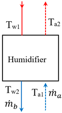
m ˙ s w m ˙ a ω a 2 ω a 1 = m ˙ b
Energy balance can be described as follows:
m ˙ b   h w 2 m ˙ s w   h w 1 = m ˙ a ( h a 1 h a 2 )
Energies 17 03593 i001
The entropy generation rate is computed as follows:
S ˙ g , h = m ˙ b s w 2 m ˙ s w s w 1 + m ˙ a ( s a 2 s a 1 )
Dehumidifier equations [33]:
m ˙ f = m ˙ a ( ω a 3 ω a 1 )
m ˙ a h a 1 h a 3 + m ˙ f h f = m ˙ c ( h 4 h 5 )
S ˙ g , d = m ˙ a s a 1 s a 3 + m ˙ f s f + m ˙ c ( s 5 s 4 )
Energies 17 03593 i002
Heat exchanger [33]:
The energy balance equation through the heat exchanger is calculated as follows:
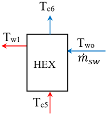
m ˙ c   h c 5 h c 6 +     m ˙ s w h w o h w 1 = 0
S ˙ g , H X = m ˙ c   s c 5 s c 6 +     m ˙ s w s w o s w 1
Energies 17 03593 i003
The heat addition to air can be computed as follows [33]:
Q ˙ a = m ˙ a ( h a 3 h a 2 )
Energies 17 03593 i004
The entropy generation rate from the air heater is calculated as follows [34]:
S ˙ g , a _ h = m ˙ a   c v a   l n T a 3 T a 2 Q ˙ s u n T s u n + Q ˙ s u n Q ˙ a T o
where Q ˙ s u n , To, and Tsun represent total solar radiation, ambient temperature, and apparent solar temperature, which are 6400 W, 300 K, and 4350 K, respectively [35].
The total exergy and exergetic efficiency of the system can be expressed as follows [35]:
S ˙ g ,   t o t a l = S ˙ g , h + S ˙ g , d + S ˙ g , H X + S ˙ g , a _ h
η e x = S ˙ g , t o t a l Q ˙ s u n 1 T o T s u n
The gained output ratio (GOR) is a performance parameter that measures the rate of condensation from the cycle. The GOR is the ratio between the latent heat of evaporation of the produced water and the input heat, which can be expressed as follows [33]:
G O R = m ˙ f   h f g Q ˙ i n
The latent heat (hfg) is determined at water saturation pressure. Q ˙ i n represents the total heat input to the system.

4. Methodology

First, the Naryan et al. [33] input parameters were utilized to validate the model. To explore the effects of dehumidifier coolants on HDH performance cycles, the simulation’s input settings were changed. The input parameters were the mass ratio, the outlet air temperature of the heater, and the flow rate. The mass ratio ranged from 2.1 to 3, and the heater’s outlet air temperature varied from 65 °C to 92 °C. The air flow rate varied from 0.4 to 0.7 kg/s.

Validation

In this section, the simulation model will be evaluated against a prior study [33]. This study employed water as a coolant for the dehumidifier. As shown in Table 3, the error ratio between the simulation model and the previous research [33] spanned from 0% to 0.68%, indicating good agreement for the application of the simulation model.

5. Results

5.1. Effect of Mass Ratio

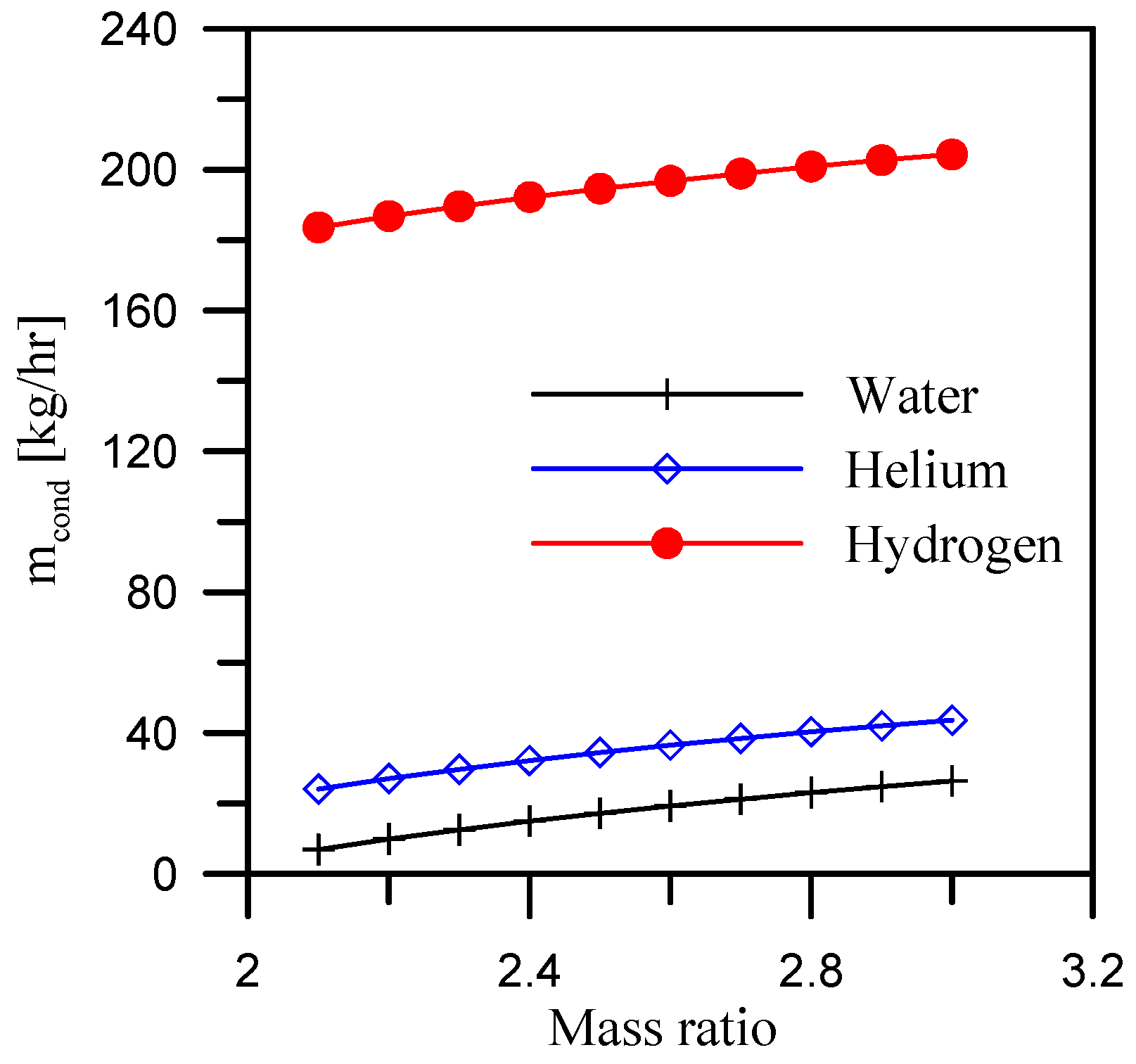
This section will investigate the impacts of mass ratio M a s s r a t i o = m ˙ s w m ˙ a on study parameters at a constant seawater mass flow rate in the humidifier of 1.5 kg/s. Figure 2 depicts the condensation rate ( m ˙ f )  with mass ratios for three different dehumidifier working fluids. At a constant mass flow rate of the dehumidifier’s working fluid, the condensation rate rises with the mass ratio. The increased mass ratio is caused by a decrease in air flow rate while maintaining a constant seawater flow rate. As a result, a low air flow rate allows to spread throughout the dehumidifier and helps to make good contact with the coil, which promotes heat transfer and raises the condensation rate. Hydrogen, when used as a working fluid in a dehumidifier, achieves the maximum condensation rate. Hydrogen has a higher specific heat than water and helium. This improves heat transfer and absorbs more heat from the air, resulting in a higher condensation rate. The average condensation rates are 17.59 kg/h, 34.85 kg/h, and 195.04 kg/h when the dehumidifier cooling fluids are water, helium, and hydrogen, respectively.
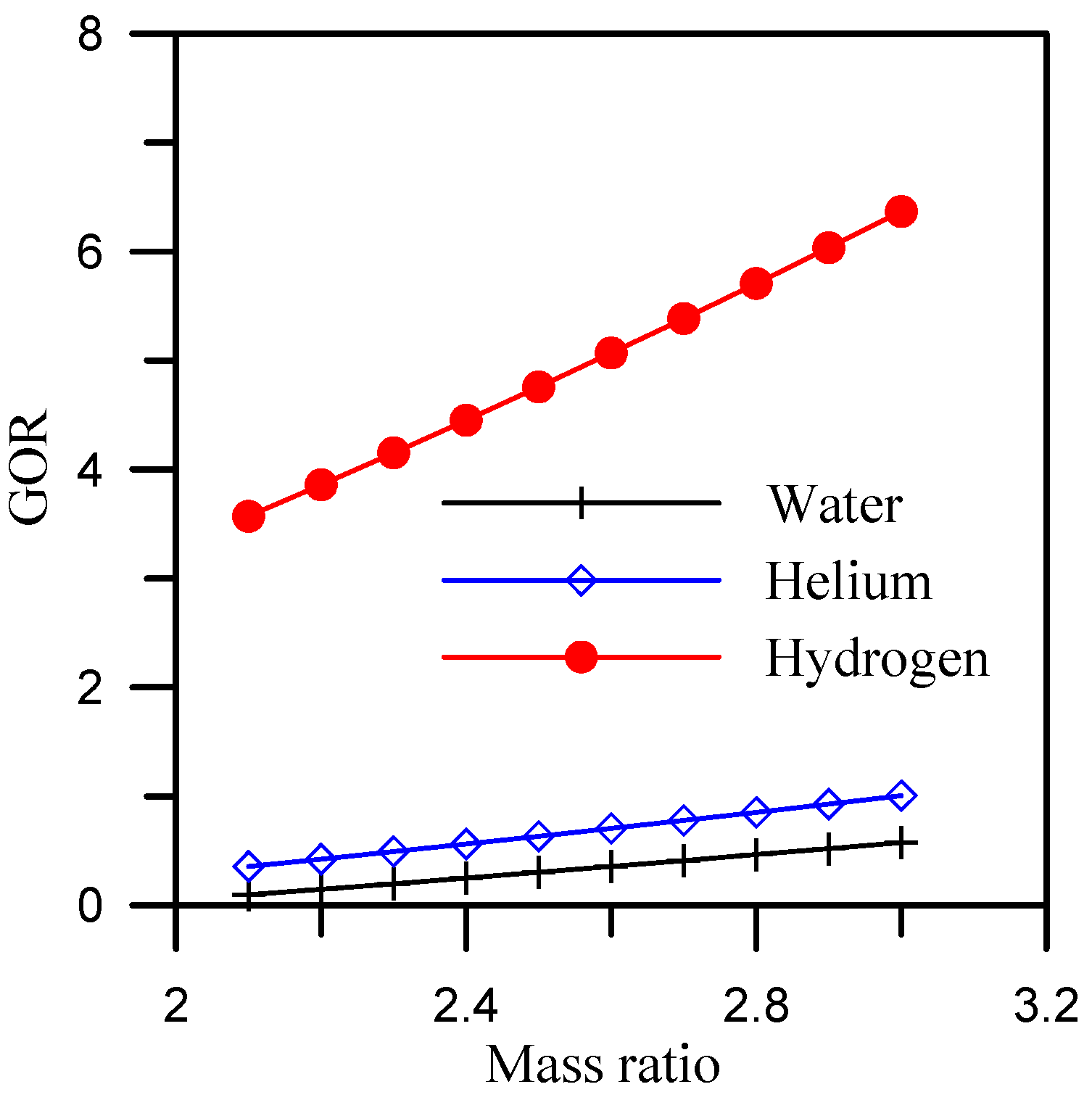
Figure 3 depicts the influence of mass ratio on GOR while utilizing various working fluids for a dehumidifier. The GOR is dependent on the condensation rate (see Equation (13)); hence, it follows the same trend as the condensation rate, and hydrogen and helium have higher GOR values than water. The average GOR value obtained when employing water, helium, and hydrogen as working fluids in a dehumidifier is 0.58, 1.01, and 6.37, respectively.
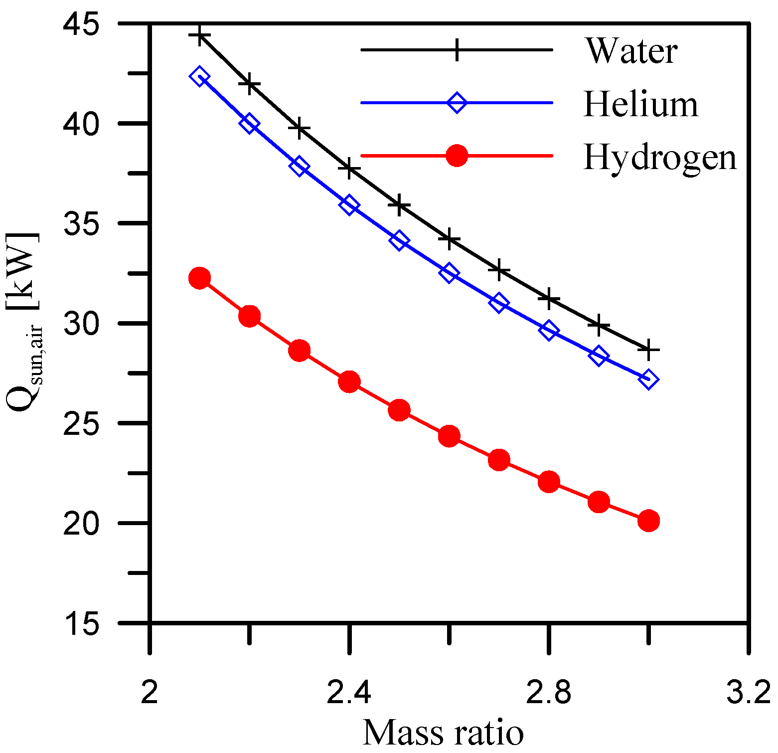
Figure 4 depicts the required heat for heating air from a solar air heater. This figure demonstrates how mass ratio affects air heating with various dehumidifier fluids. For all fluids in the dehumidifier, the air heater capacity decreases as mass ratio increases. Because of the low air flow, the air heating capacity reduces despite the fact that the air temperature differential through the air heater is large. The use of hydrogen requires the least amount of air heating, allowing for the use of a small solar collector and thus being less expensive than the other two dehumidifier coolants. The average solar air heat required when using hydrogen as a working fluid for dehumidifier is 28.6% and 24.9% lower than the average solar air heat when using water and helium as working fluids in the dehumidifier, respectively.
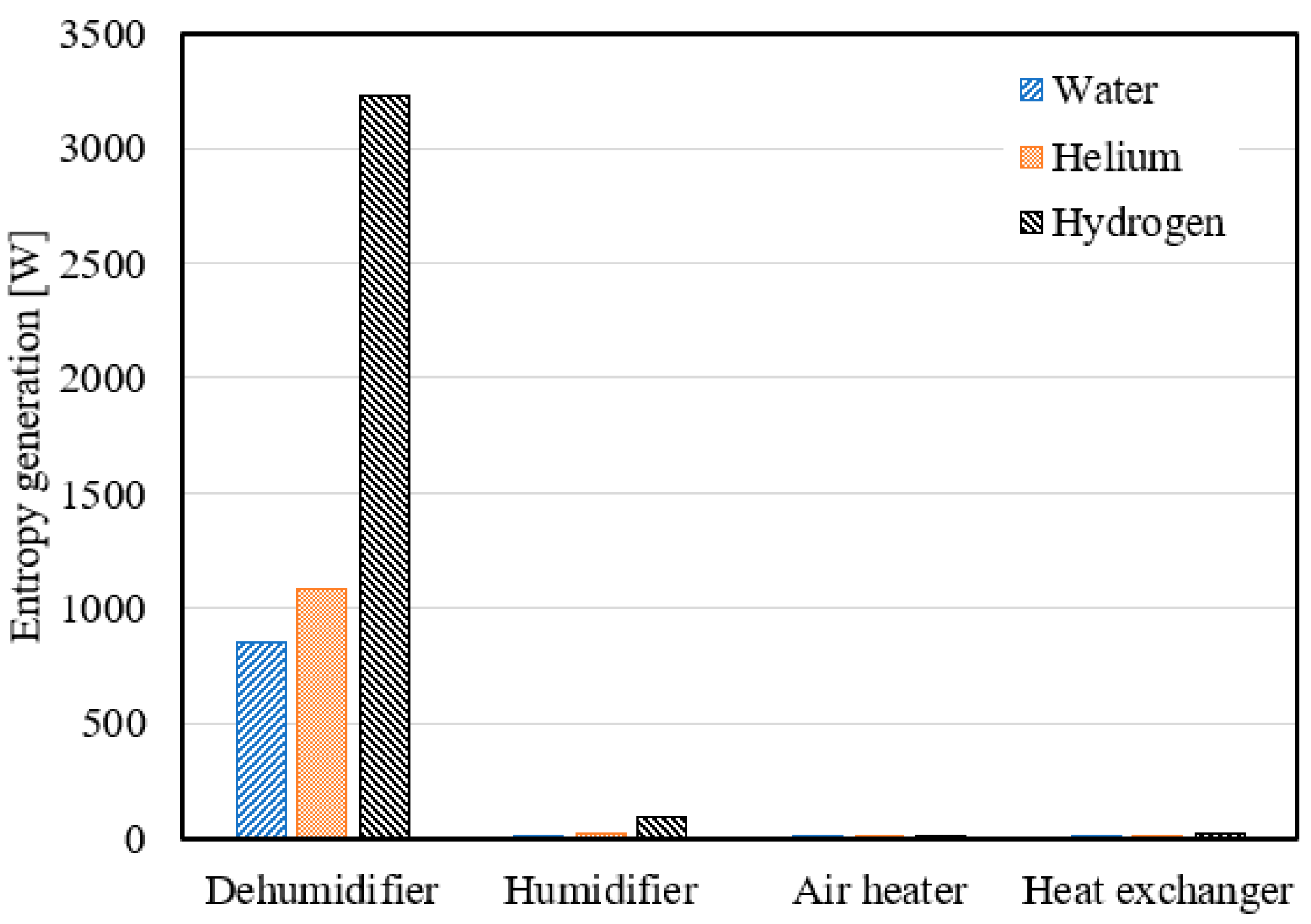
The entropy generation for each system component is shown in Figure 5. According to this figure, the air heater produces the least amount of entropy, while the dehumidifier generates the most. The largest entropy generation from a dehumidifier is 3231.8 W when hydrogen is used as a coolant in a dehumidifier.
The effect of mass ratio and dehumidifier working fluids on entropy generation in the system is seen in Figure 6. The system generates the most entropy when the dehumidifier uses hydrogen, and the least when the dehumidifier uses water. The average entropy generation for the system utilizing hydrogen in the dehumidifier is 3.8 times and 2.9 times more than the average entropy generation for the systems using water and helium, respectively.
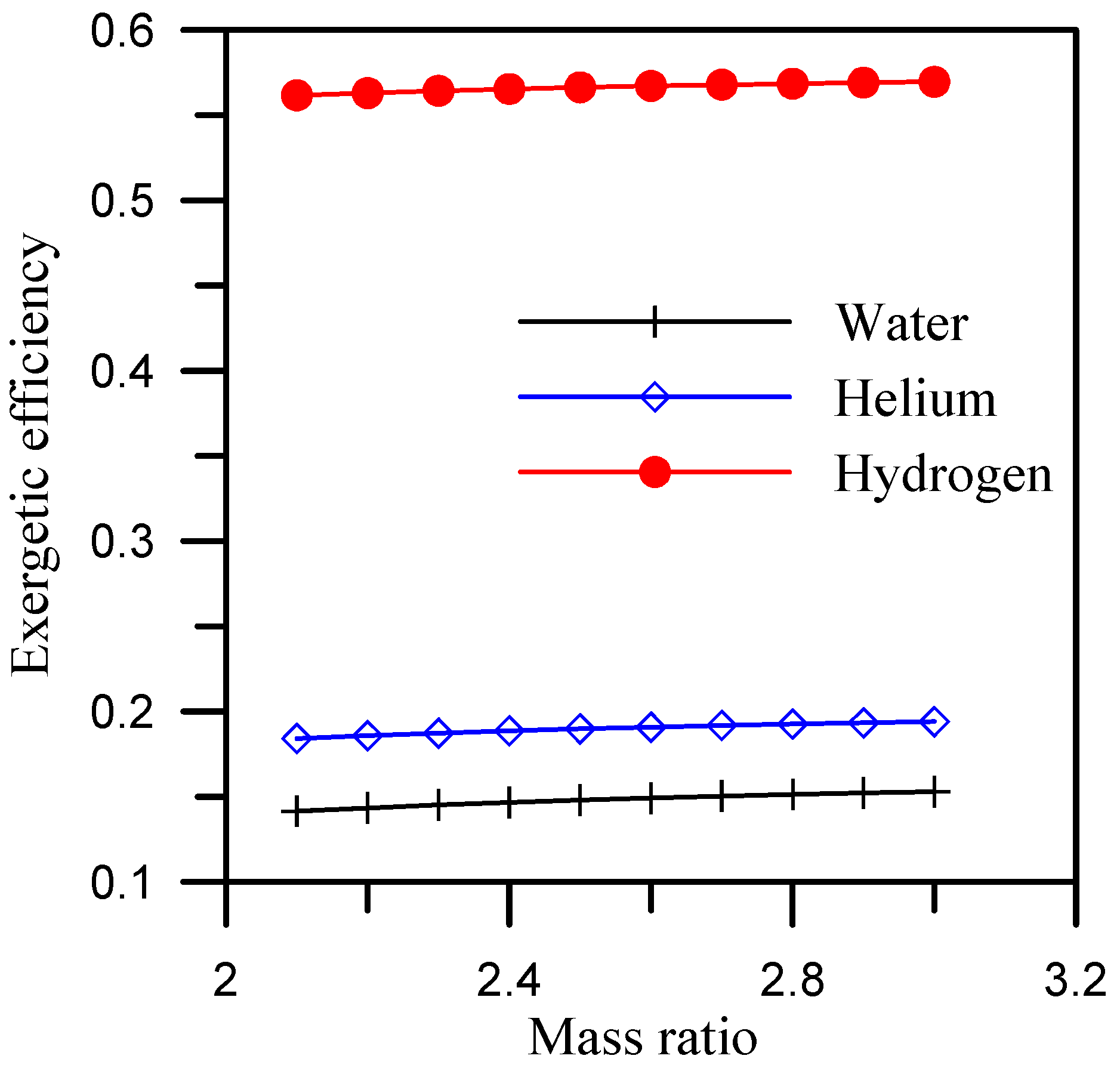
Figure 7 displays the cycle’s exergetic efficiency. The exergetic efficiency trend corresponds to the total entropy generation of the cycle. This is because the system’s exergetic efficiency is computed assuming a constant sun heat rate. The cycle with a hydrogen-cooled dehumidifier has the maximum exergetic efficiency, which is greater than 0.55.

5.2. Effect of Heater’s Outlet Air Temperature

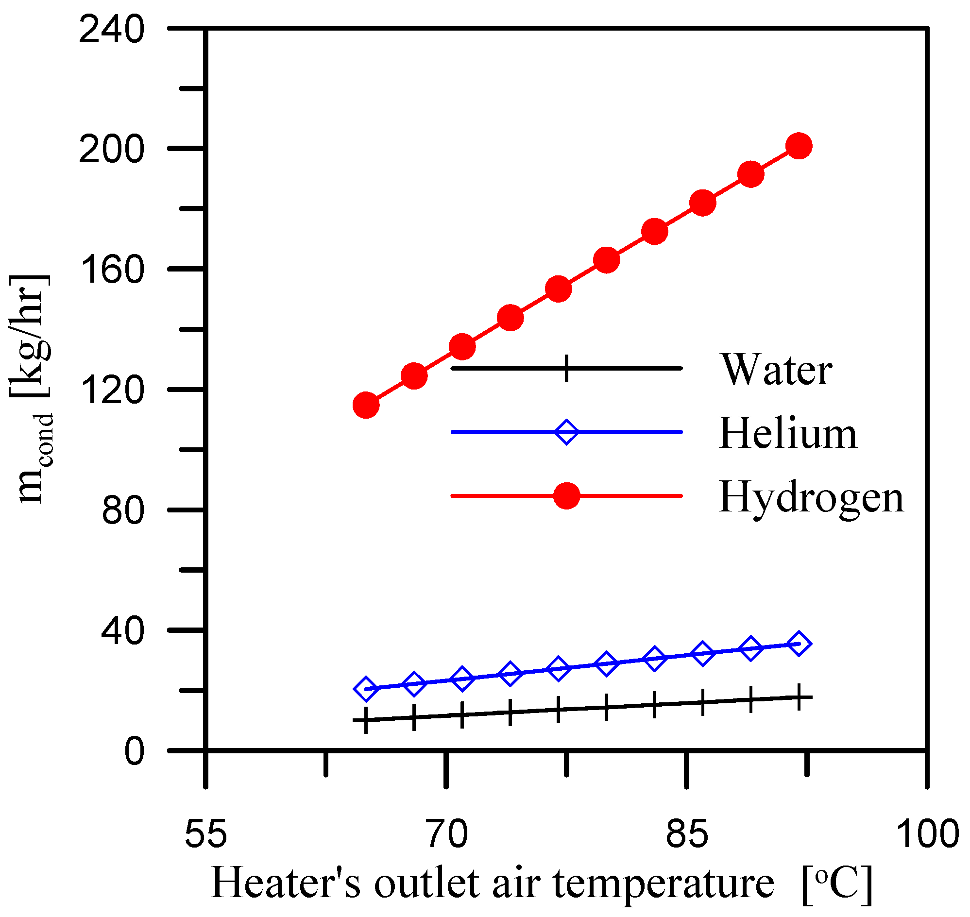
This section will present the impacts of the heater’s outlet air temperature on the system with a constant mass ratio of 10.2. The outlet air temperature range of the heater is 65 °C to 92 °C. Figure 8 depicts the relationship between condensation rate and the heater’s outlet air temperature when using different dehumidifier coolants. For the three dehumidifier coolants, the condensation rate increases as the heater’s outlet air temperature increases. This is due to sufficient cooling of the air in the dehumidifier when the air is high in temperature, resulting in a high condensation rate. However, the dehumidifier’s hydrogen coolant produces a high condensation rate. When hydrogen is used as a dehumidifier coolant instead of water and helium, the average condensation rate increases by 11.3 times and 5.6 times, respectively.
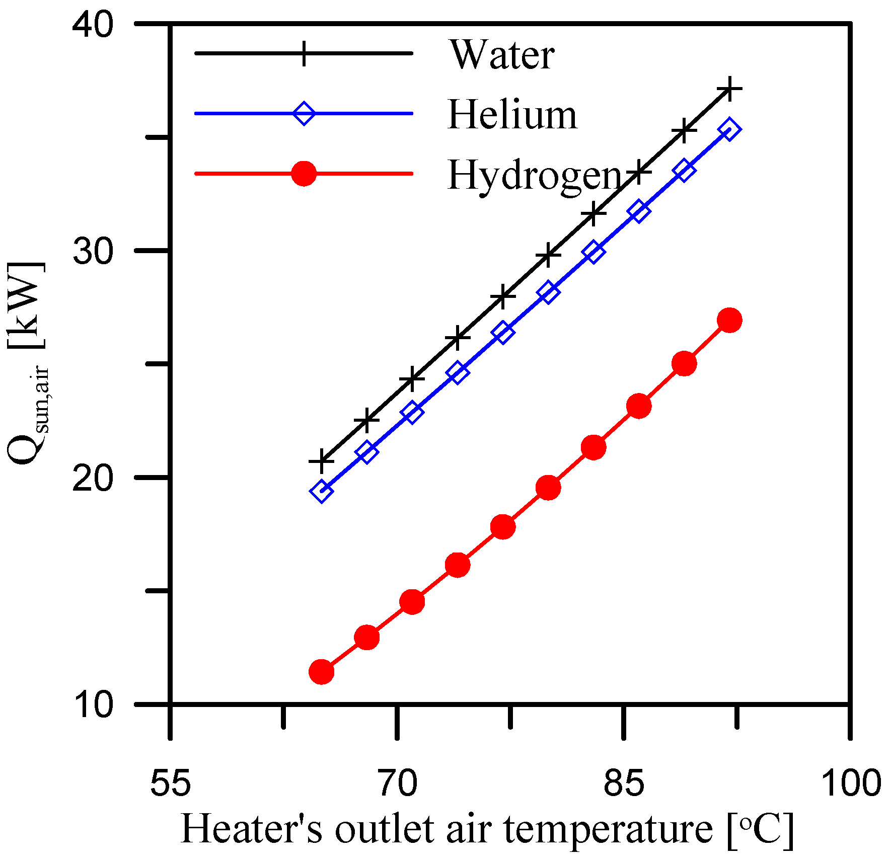
Figure 9 demonstrates the GOR with the heater’s outlet air temperature. The GOR decreases as heater’s outlet air temperature decreases. To achieve a high heater output air temperature, more heat is used from the heater, resulting in a decrease in GOR despite an increase in condensation rate. The highest GOR can be achieved by employing hydrogen as a coolant in the dehumidifier and maintaining a low heater outlet air temperature. When hydrogen is used as a dehumidifier coolant, the system produces an average GOR of 5.4. This trend is confirmed by Figure 10, which shows that the dehumidifier’s hydrogen coolant requires the least amount of heat for the air. The quantity of heat required to heat the air rises in proportion to the temperature of the air leaving from the heater. The average quantity of heat required for air when using hydrogen as a dehumidifier coolant is 34.7% and 30.9% lower than the average quantity of heat required for air when using water and helium as dehumidifier coolants.
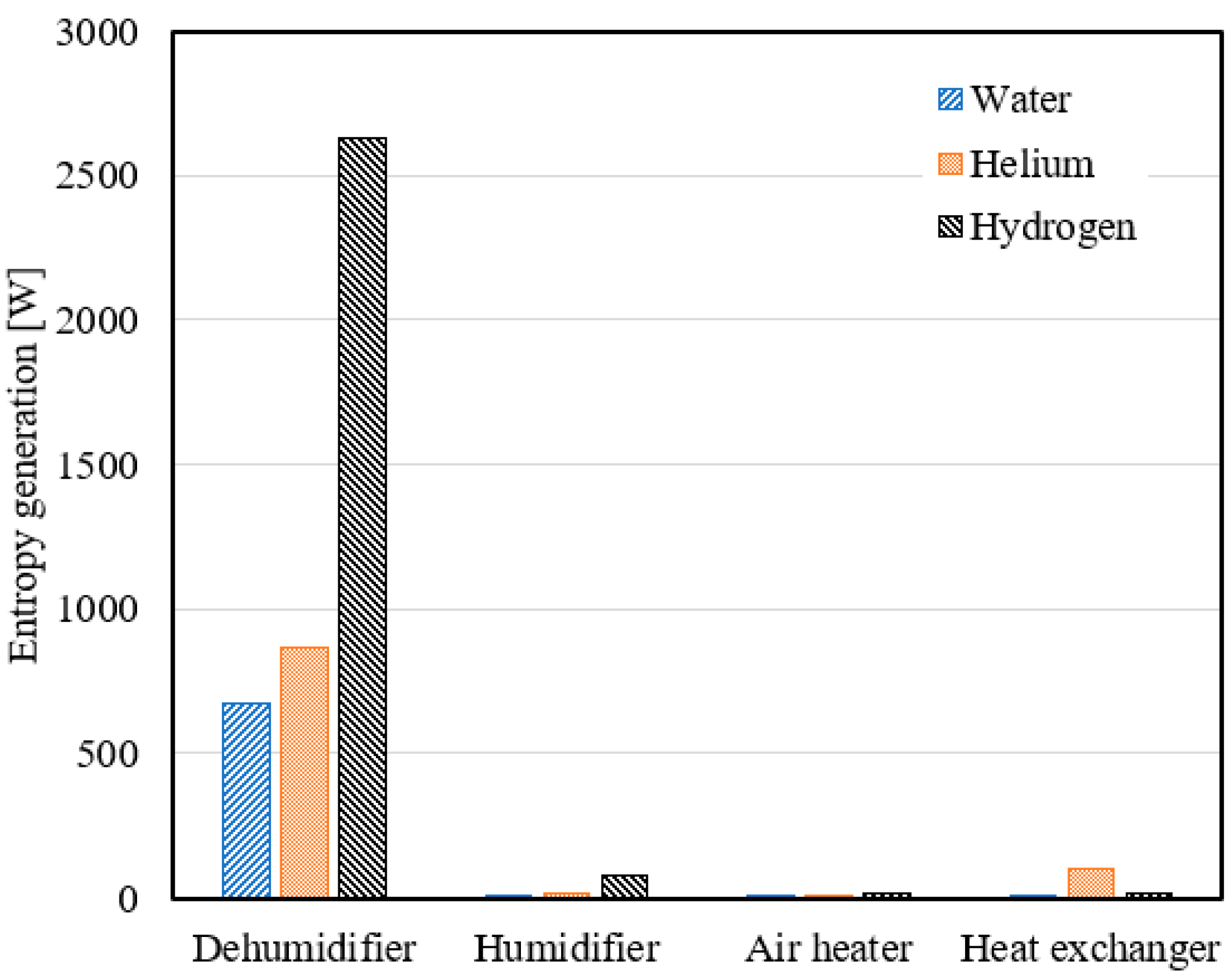
Figure 11 shows the average entropy generation over a range of heater outlet air temperatures. As illustrated, dehumidifiers have a greater effect on entropy generation than other system components. When the dehumidifier employs water, helium, and hydrogen as dehumidifier coolants, the average entropy generation is 670.9 W, 863.4 W, and 2626.9 W, respectively.
Figure 12 displays the system’s entropy generation as a function of the heater outlet air temperature. The entropy generated by the three dehumidifier coolants is proportional to the heater’s outlet air temperature. This is due to an increase in entropy generated by the dehumidifier. The system generates the most and the least entropy when hydrogen and water are used as coolants in the dehumidifier, respectively. When hydrogen is used as a coolant in the dehumidifier, the average entropy generation is 3 times and 3.9 times more than when helium and water are used.
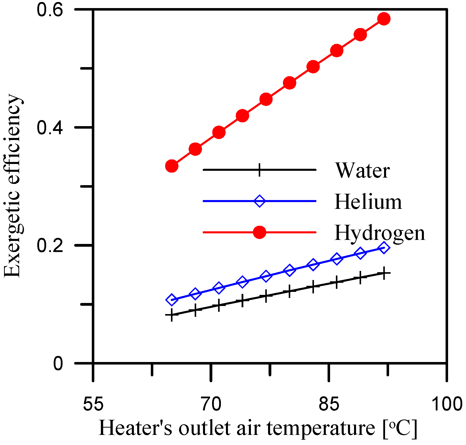
Figure 13 displays the exergetic efficiency of increasing the heater outlet air temperature. The exergetic efficiency increases as the heater outlet air temperature increases. This is due to the behavior of entropy generation. When hydrogen is used as coolant in the dehumidifier, the average exergetic efficiency is 0.46 over the heater outlet air temperature range.

5.3. Effect of Air Flow Rate at Constant Mass Ratio

Figure 14 displays the condensation rate with varying air flow rates, a constant mass ratio of 2.5, and a constant heater outlet air temperature of 90 °C. The condensation rate decreases as air flow rate increases due to poor condensation caused by a high air flow rate in the dehumidifier. However, hydrogen has a greater effect when applied. Over the range of air flow rates, employing hydrogen coolant instead of water and helium coolants in the dehumidifier increases the average condensation rate by 9.2 times and 5.1 times, respectively.
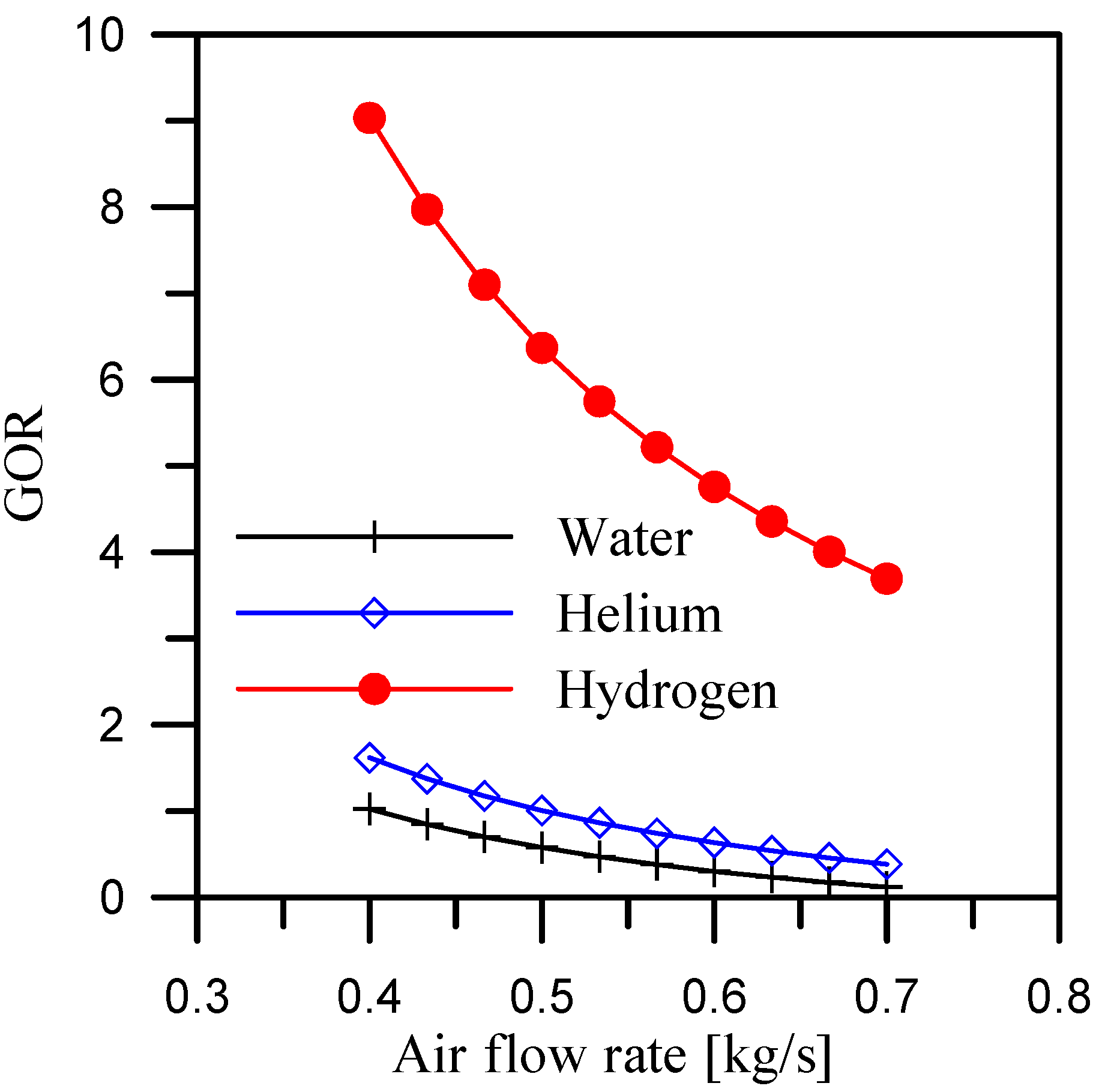
Figure 15 depicts the GOR when utilizing three coolants for the dehumidifier at various air flow rates. According to the condensation rate trend, the GOR is inversely proportional to the airflow rate. All three coolants reach their maximum GOR at an air flow rate of 0.4 kg/s. When hydrogen is utilized as a coolant for the dehumidifier, the average GOR is 5.8 over the air flow rate range of 0.4 to 0.7 kg/s.
Figure 16 shows the air heat rate with a variable air flow rate, a constant mass ratio, and a constant heater outlet air temperature. A higher heat rate is required to overcome the increased air flow rate and maintain a consistent air temperature at the heater exit. When hydrogen is used as a coolant for a dehumidifier, the air requires less heat. This is determined by the air temperature, ensuring that the humidifier and dehumidifier’s effectiveness remains consistent. As a result, when hydrogen is used as the coolant for the dehumidifier, the system is small.
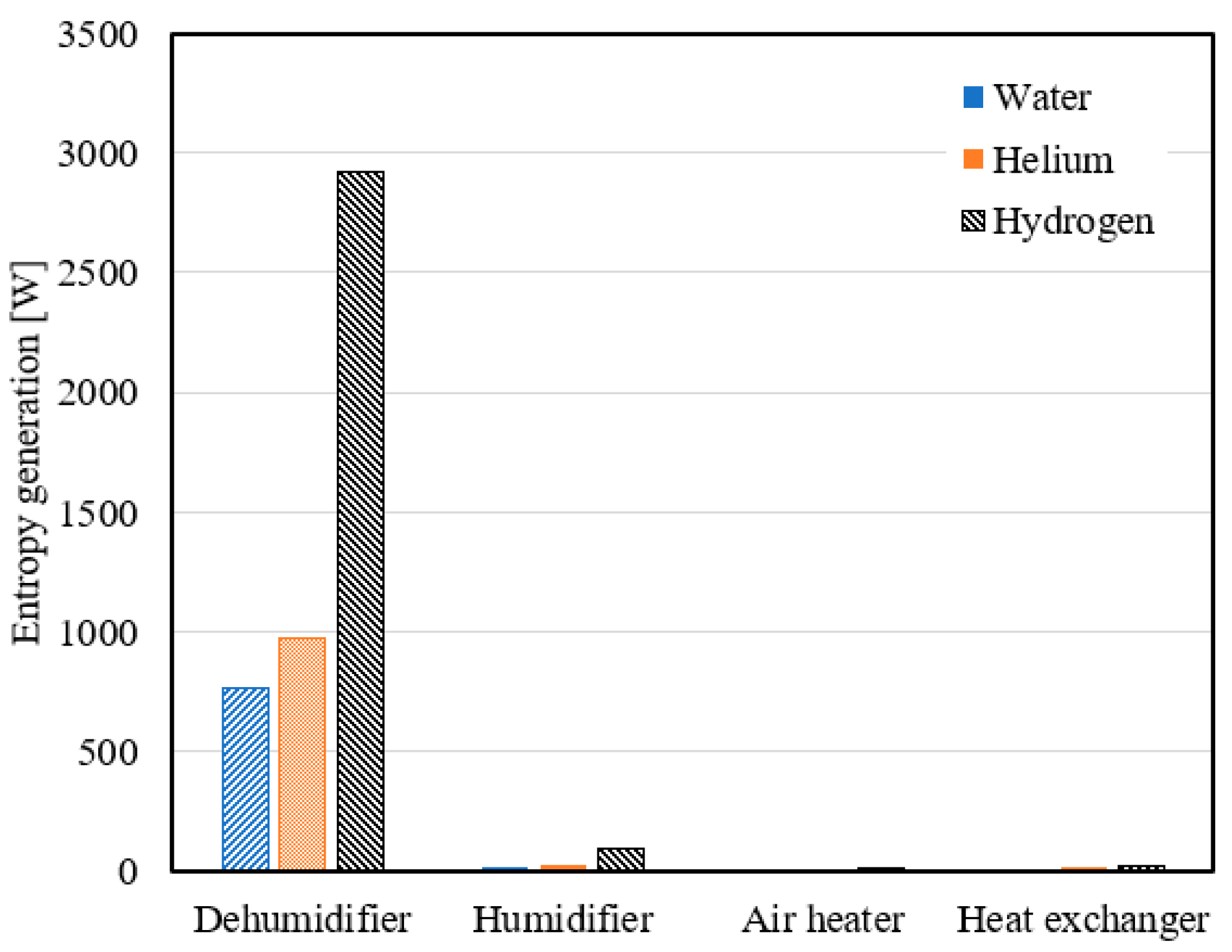
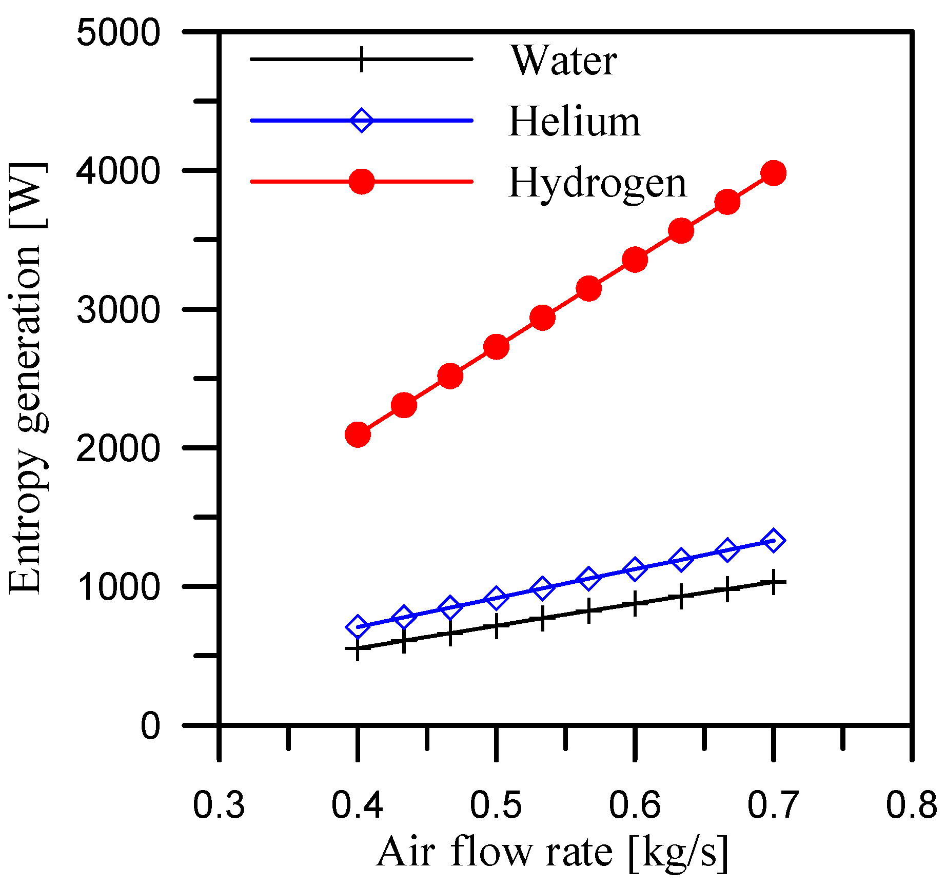
Figure 17 displays the average entropy generation for each system component with varying air flow rate and constant mass ratio. The humidifier generates less entropy than a dehumidifier. In addition, the air heater has the lowest entropy value. The dehumidifier generates 763.1 W, 974.3 W, and 2918.3 W of entropy when water, helium, and hydrogen are used as dehumidifier coolants, respectively. Figure 18 displays the entropy generation for a system with a variable air flow rate, a constant mass ratio of 2.5, and a constant heater outlet air temperature of 90 °C. When hydrogen, water, and helium are utilized as dehumidifier coolants, entropy generation increases with the rate of air flow. Furthermore, when hydrogen is employed as a coolant in a dehumidifier, the system produces the maximum entropy compared to water or helium, because the entropy generated by the dehumidifier has a greater impact on the system’s entropy generating trend. Thus, Figure 19 illustrates that when hydrogen is used as a coolant in the dehumidifier, the system has a high exergetic efficiency; it increases by 3.82 times and 2.98 times when compared to helium and water coolants.

6. Conclusions

This study looks at the characteristics of a humidification-dehumidification desalination system that uses three dehumidifier coolants. The coolants are water, helium, and hydrogen, which pass through a dehumidifier with a constant flow rate and temperature difference. The characteristics of this study can be summarized as follows:
  • When hydrogen is used as the coolant for the dehumidifier, the GOR is maximized. The average GOR across the heater outlet temperature range of 65 °C to 92 °C is 5.4, while it reaches 5.8 and 6.37, respectively, for air flow rate and mass ratio ranges of 0.4 to 0.7 kg/s and 2.1 to 3.
  • When comparing the requirements for the three dehumidifier coolants, hydrogen has the lowest air heating rate. The average value of heat required for air when using hydrogen as a dehumidifier coolant is 34.7% and 30.9% less than when using water and helium as dehumidifier coolants over the study range of heater outlet air temperatures (65 °C to 92 °C).
  • Using hydrogen as a coolant in the dehumidifier resulted in average entropy generation of 3231.8 W, 2918.3 W, and 2626.9 W at a mass ratio range of 2.1 to 3, heater output temperature range of 65 °C to 92 °C, and air flow rate range of 0.4 to 0.7 kg/s, respectively.
  • A hydrogen-cooled dehumidifier has an exergetic efficiency of 0.55 and 0.46 over a range of mass ratio of 2.1 to 3 and range of heater outlet temperature of 65 °C to 92 °C, respectively.
  • The system size will be affected when hydrogen is utilized as a coolant in a dehumidifier, but caution must be exercised because hydrogen is dangerous.
Finally, according to the findings of this study, hydrogen, from the thermodynamics properties, appears to improve the performance of the HDH desalinization cycles; however, when considering the safety issues and the actual requirements in terms of heat exchanger surface area and additional equipment that must be introduced to cool down the hydrogen flow, it appears that installation and operation costs could be significant compared to the traditional solution of using water. As a result, more extensive investigation is required to fully analyses hydrogen’s potential as a heat transfer medium.

Author Contributions

Conceptualization, A.M.M.A. and F.N.M.E.; Methodology, A.M.M.A. and F.N.M.E.; Software, A.M.M.A. and F.N.M.E.; Validation, A.M.M.A. and F.N.M.E.; Formal analysis, A.M.M.A., F.N.M.E. and R.T.; Investigation, A.M.M.A. and F.N.M.E.; Resources, A.M.M.A. and F.N.M.E.; Writing – original draft, A.M.M.A. and F.N.M.E.; Writing – review & editing, A.M.M.A., F.N.M.E. and R.T.; Visualization, A.M.M.A. and F.N.M.E.; Supervision, A.M.M.A. and F.N.M.E. All authors have read and agreed to the published version of the manuscript.

Funding

This research received no external funding.

Data Availability Statement

The original contributions presented in the study are included in the article, further inquiries can be directed to the corresponding author/s.

Conflicts of Interest

The authors declare no conflict of interest.

Abbreviations

Nomenclatural
m ˙ Mass flow rate [kg/s]
Q ˙ Heat rate [W]
S ˙ Entropy generation rate [W/K]
c v Specific heat at constant volume [J/kg.K]
GORGained output ratio [-]
hSpecific enthalpy [J/kg]
hfgLatent heat [J/kg]
sSpecific entropy [J/kg.K]
TTemperature [K]
ω Absolute humidity [kg/kg dry air]
Subscripts
swSeawater
aAir
bBrine
fFresh water
gGeneration
oAmbient
sunSun
inInlet
hHumidifier
dDehumidifier
a_hAir heater
HXHeat exchanger
cCoolant

References

  1. Mazzucato, M.; Okonjo-Iweala, N.; Rockström, J.; Shanmugaratnam, T. Turning the Tide: A Call to Collective Action; Global Commission on the Economics of Water: Paris, France, 2023. [Google Scholar]
  2. Ahmed, M.A.; Zubair, S.M.; Abido, M.A.; Bahaidarah, H.M. An innovative closed-air closed-desiccant HDH system to extract water fromthe air: A case for zero-brine discharge system. Desalination 2018, 445, 236–248. [Google Scholar] [CrossRef]
  3. Ali, M.T.; Fath, H.E.S.; Armstrong, P.R. A comprehensive techno-economical review of indirect solar desalination. Renew. Sust. Energ. Rev. 2011, 15, 4187–4199. [Google Scholar] [CrossRef]
  4. Fritzmann, C.; Löwenberg, J.; Wintgens, T.; Melin, T. State-of-the-art of reverse osmosis desalination. Desalination 2007, 216, 1–76. [Google Scholar] [CrossRef]
  5. Narayan, G.P.; Sharqawy, M.H.; Summers, E.K.; Lienhard, V.J.H.; Zubair, S.M.; Antar, M.A. The potential of solar-driven humidification-dehumidification desalination for small-scale decentralized water production. Renew. Sust. Energ. Rev. 2010, 14, 1187–1201. [Google Scholar] [CrossRef]
  6. Klausner, J.F.; Mei, R.; Li, Y.; Knight, J.; Jogi, V. Innovative Fresh Water Production Process for Fossil Fuel Plants; University of Florida: Gainesville, FL, USA, 2005. Available online: https://www.osti.gov/servlets/purl/862097 (accessed on 25 June 2024). [CrossRef]
  7. Al-Enezi, G.; Ettouney, H.; Fawzy, N. Low temperature humidification dehumidification desalination process. Energy Convers. Manag. 2006, 47, 470–484. [Google Scholar] [CrossRef]
  8. Li, X.; Yuan, G.; Wang, Z.; Li, H.; Xu, Z. Experimental study on a humidification and dehumidification desalination system of solar air heater with evacuated tubes. Desalination 2014, 351, 1–8. [Google Scholar] [CrossRef]
  9. Yıldırım, C.; Solmus, I. A parametric study on a humidification dehumidification (HDH) desalination unit powered by solar air and water heaters. Energy Convers. Manag. 2014, 86, 568–575. [Google Scholar] [CrossRef]
  10. Shatat, M.; Omer, S.; Gillott, M.; Riffat, S. Theoretical simulation of small scale psychometric solar water desalination system in semi-arid region. Appl. Therm. Eng. 2013, 59, 232–242. [Google Scholar] [CrossRef]
  11. Kumar, S.; Dubey, A.; Tiwari, G.N. A solar still augmented with an evacuated tube collector in forced mode. Desalination 2014, 347, 15–24. [Google Scholar] [CrossRef]
  12. Liu, X.; Chen, W.; Ming, G.; Shen, S.; Cao, G. Thermal and economic analyses of solar desalination system with evacuated tube collectors. Sol. Energy 2013, 93, 144–150. [Google Scholar] [CrossRef]
  13. Al-Sulaimana, F.A.; Zubair, I.M.; Atif, M.; Gandhidasan, P.; Al-Dini, S.A.; Antar, M.A. Humidification dehumidification desalination system using parabolic trough solar air collector. Appl. Therm. Eng. 2015, 75, 809–816. [Google Scholar] [CrossRef]
  14. Mohamed, A.M.I.; El-Minshawy, N.A. Theoretical investigation of solar humidification–dehumidification desalination system using parabolic trough concentrators. Energy Convers. Manag. 2011, 52, 3112–3119. [Google Scholar] [CrossRef]
  15. Dayem, A.M.A.; Fatouh, M. Experimental and numerical investigation of humidification/dehumidification solar water desalination systems. Desalination 2009, 247, 594–609. [Google Scholar] [CrossRef]
  16. Gabrielli, P.; Gazzanib, M.; Novatic, N.; Sutter, L.; Simonetti, R.; Molinaroli, L.; Manzolini, G.; Mazzotti, M. Combined water desalination and electricity generation through a humidification-dehumidification process integrated with photovoltaic-thermal modules: Design, performance analysis and techno-economic assessment. Energy Convers. Manag. X 2019, 1, 100004. [Google Scholar] [CrossRef]
  17. Muthusamy, C.; Srithar, K. Energy and exergy analysis for a humidification–dehumidification desalination system integrated with multiple inserts. Desalination 2015, 367, 49–59. [Google Scholar] [CrossRef]
  18. Raj, P.R.; Jayakumar, J.S. Performance analysis of humidifier packing for humidification dehumidification desalination system. Therm. Sci. Eng. Prog. 2022, 27, 101118. [Google Scholar]
  19. He, W.F.; Chen, J.J.; Han, D.; Luo, L.T.; Wang, X.C.; Zhang, Q.Y.; Yao, S.Y. Energetic, entropic and economic analysis of an open-air, open-water humidification dehumidification desalination system with a packing bed dehumidifier. Energy Convers. Manag. 2019, 199, 112016. [Google Scholar] [CrossRef]
  20. Elsafi, A.M. Integration of humidification-dehumidification desalination and concentrated photovoltaic-thermal collectors: Energy and exergy-costing analysis. Desalination 2017, 424, 17–26. [Google Scholar] [CrossRef]
  21. Alrbai, M.; Enizat, J.; Hayajneh, H.; Qawasmeh, B.; Al-Dahidi, S. Energy and exergy analysis of a novel humidification-dehumidification desalination system with fogging technique. Desalination 2022, 522, 115421. [Google Scholar] [CrossRef]
  22. Garg, K.; Das, S.; Tyagi, H. Thermal design of a humidification-dehumidification desalination cycle consisting of packed-bed humidifier and finned-tub e dehumidifier. Int. J. Heat Mass Transf. 2022, 183, 122153. [Google Scholar] [CrossRef]
  23. Saha, P.; Tan, X.; Klausner, J.; Abbasi, B.; Benard, A. Comparative investigation on direct contact crossflow and direct contact counterflow packed beds condensers: Experimental and modeling analyses. Appl. Therm. Eng. 2024, 236, 121777. [Google Scholar] [CrossRef]
  24. Nada, S.A.; Fouda, A.; Mahmoud, M.A.; Elattar, H.F. Experimental investigation of air-conditioning and HDH desalination hybrid system using new packing pad humidifier and strips-finned helical coil. Appl. Therm. Eng. 2021, 185, 116433. [Google Scholar] [CrossRef]
  25. Hu, T.; Hassabou, A.H.; Spinnler, M.; Polifke, W. Performance analysis and optimization of direct contact condensation in a PCM fixed bed regenerator. Desalination 2011, 280, 232–243. [Google Scholar] [CrossRef]
  26. Tan, X.; Saha, P.; Klausner, J.; Abbasi, B.; Benard, A. Modeling and experimental validation of direct contact crossflow packed beds condenser used in HDH desalination systems. Desalination 2023, 548, 116297. [Google Scholar] [CrossRef]
  27. Zhao, Y.; Zheng, H.; Liang, S.; Zhang, N.; Ma, X. Experimental research on four-stage cross flow humidification dehumidification (HDH) solar desalination system with direct contact dehumidifiers. Desalination 2019, 467, 147–157. [Google Scholar] [CrossRef]
  28. He, W.F.; Wu, F.; Wen, T.; Kong, Y.P.; Han, D. Cost analysis of a humidification dehumidification desalination system with a packed bed dehumidifier. Energy Convers. Manag. 2018, 171, 452–460. [Google Scholar] [CrossRef]
  29. Zhang, Y.; Zhu, C.; Zhang, H.; Zheng, W.; You, S.; Zhen, Y. Experimental study of a humidification dehumidification desalination system with heat pump unit. Desalination 2018, 442, 108–117. [Google Scholar] [CrossRef]
  30. Capocelli, M.; Balsamo, M.; Mazzeo, L.; Luberti, M. Thermodynamic analysis of the humidification-dehumidification-adsorption (HDHA) desalination process. Desalination 2023, 554, 116510. [Google Scholar] [CrossRef]
  31. Capocelli, M.; Balsamo, M.; Lancia, A.; Barba, D. Process analysis of a novel humidification-dehumidification-adsorption (HDHA) desalination method. Desalination 2018, 429, 155–166. [Google Scholar] [CrossRef]
  32. Klein, S.A. Engineering Equation Solver (EES) V9; F-Chart Software: Madison, WI, USA, 2015; Available online: http://www.fchart.com (accessed on 16 May 2024).
  33. Narayan, G.P.; Sharqawy, M.H.; Lienhard, V.J.H.; Zubair, S.M. Thermodynamic analysis of humidification dehumidification desalination cycles. Desalination Water Treat. 2010, 16, 339–353. [Google Scholar] [CrossRef]
  34. Milton, M.; Manuel, R.; Rodrigo, C. Entropy generation analysis for the design of a flat plate solar collector with fins. Dyna 2020, 87, 199–208. [Google Scholar]
  35. Ge, Z.; Wang, H.; Wang, H.; Zhang, S.; Guan, X. Exergy Analysis of Flat Plate Solar Collectors. Entropy 2014, 16, 2549–2567. [Google Scholar] [CrossRef]
Figure 1. Schematic of the closed-air open-water cycle with dehumidifier coolant.
Energies 17 03593 g001
Figure 2. Condensation rate with mass ratio.
Energies 17 03593 g002
Figure 3. GOR with mass ratio.
Energies 17 03593 g003
Figure 4. Heat rate for air with mass ratio.
Energies 17 03593 g004
Figure 5. Entropy generation for system components with mass ratio.
Energies 17 03593 g005
Figure 6. Total entropy generation with mass ratio.
Energies 17 03593 g006
Figure 7. Exergetic efficiency with mass ratio.
Energies 17 03593 g007
Figure 8. Condensation rate with heater outlet air temperatures.
Energies 17 03593 g008
Figure 9. Relation between GOR and heater outlet air temperatures.
Energies 17 03593 g009
Figure 10. Heat rate for air with heater outlet air temperatures.
Energies 17 03593 g010
Figure 11. Entropy generation for each component with heater outlet air temperatures.
Energies 17 03593 g011
Figure 12. Total entropy generation with heater outlet air temperatures.
Energies 17 03593 g012
Figure 13. Exergetic efficiency with heater outlet air temperatures.
Energies 17 03593 g013
Figure 14. Effect of air flow rate and dehumidifier coolants on condensation rate.
Energies 17 03593 g014
Figure 15. Relation among the effects of air flow rate, dehumidifier coolants, and GOR.
Energies 17 03593 g015
Figure 16. Heat rate for air with air flow rate and dehumidifier coolants.
Energies 17 03593 g016
Figure 17. Entropy generation for each component with air flow rate and dehumidifier coolants.
Energies 17 03593 g017
Figure 18. Total entropy generation with air flow rate and dehumidifier coolants.
Energies 17 03593 g018
Figure 19. Exergetic efficiency with air flow rate and dehumidifier coolants.
Energies 17 03593 g019
Table 1. Thermophysical properties of coolants used in dehumidifier at 25 °C and 1 atm.
PropertiesWaterHeliumHydrogen
Molecular weight [g/mole]18.024.0032.016
Density ρ [kg/m3]997.10.1640.0823
Specific heat Cp [J/kg K]4183519314306
viscosity µ [kg/m s]8.9 × 10−41.98 × 10−59.01 × 10⁻⁶
Thermal conductivity k [W/m k]0.5950.15530.1769
Thermal diffusivity1.4 × 10−71.8 × 10−41.5 × 10−4
FlammabilityNonNonExtremely
Table 2. Simulation conditions.
ParametersRange
Coolant mass flow rate ( m ˙ c 4 ) 0.2 [kg/s]
Coolant inlet temperature (Tc4)313 [K]
Relative air humidity at the inlet (RHa1)1
Relative air humidity at the outlet (RHa2)1
Seawater inlet temperature (Two)303 [°C]
Mass ratio m ˙ s w m ˙ a 2.1:3
Ambient temperature (To)27 [°C]
Table 3. Comparison between previous results and simulation model.
ParametersNaryan et al. [33]SimulationError %
mcond0.00590.005940.67797%
Ta134.234.170.08772%
Ta251.451.380.03891%
Tw162.7963.150.57334%
Tw237.0537.070.05398%
mb0.1440.1440%
GOR2.92.931.03448%
Disclaimer/Publisher’s Note: The statements, opinions and data contained in all publications are solely those of the individual author(s) and contributor(s) and not of MDPI and/or the editor(s). MDPI and/or the editor(s) disclaim responsibility for any injury to people or property resulting from any ideas, methods, instructions or products referred to in the content.