1. Introduction
The theoretical research of porous media originated from a series of experiments conducted by Henry Darcy in 1856 on the downward flow of water through filter sands, and it was found that the rate of flow is given by [
1]
where
q is the volume flow rate,
l is the thickness of the sand,
K is a coefficient for permeation, and
h2 and
h1 are the height of the outlet and inlet of the filter, respectively. Subsequently, the equation is known as the Darcy Law throughout the world. In the following decades, scholars engaged in the theoretical research of porous media from a multitude of perspectives, including the pressure drop against distinct velocities, the characteristics of flow in multi-layer porous media, two-phase flow in porous media, and so forth. The outcomes have impelled the applications of porous media [
2,
3,
4].
Porous media was initially employed in filters covering fields such as ocean protection and the oil industry due to its larger surface area and the resulting enhanced purification performance. In response to the growing demand for enhanced cooling capabilities, porous media has been employed in nuclear reactors such as high-temperature reactors [
5].
In the recent years, fusion reactors have attracted considerable attention worldwide due to their inherent high efficiency, cleanliness and safety characteristics. In order to achieve the self-sustainability of fuel (tritium) in a fusion reaction, a tritium breeding blanket module that is installed inside the vacuum vessel of the fusion reactors is required. One of the proposed conceptual blankets contains Li
4SiO
4 and beryllium pebbles for the purpose of producing tritium and neutrons [
6]. In the design stage, the pressure drop of the pebble bed is an important parameter that should be calculated. However, traditional computational fluid dynamics, which are feasible for the simulation, would require a significant amount of calculating resources and time. Consequently, scholars have endeavored to identify a method that is both suitable and efficient for the calculation.
In this circumstance, the porous media approach has been considered in the simulation and analysis for blankets of fusion reactors in recent years. Several experiments have been conducted to assess the feasibility of this method, as evidenced by references [
7,
8]. However, the overall pressure drop of blankets using the porous media approach has not been evaluated yet. Consequently, it is essential to calculate the overall pressure using the porous media approach.
In the simulation utilizing the porous media approach, the reasonable determination of parameters is of paramount importance. The parameters of porous media are permeability and the inertial loss coefficient. Permeability is related to the viscous loss term and is employed to describe the ease with which a fluid can be forced through a porous media by external force. The inertial loss coefficient is a parameter depicting the pressure drop when a fluid flows through a porous media zone. The parameters have been defined in a number of different formulas by scholars using experimental data in the past few decades. However, the complex structure of the pebble bed in the blanket with a wide range of superficial velocities requires a suitable determination method for the parameters that could not be obtained directly from the empirical formulas when using the porous media approach for calculation. Therefore, the purpose of this paper is to investigate an appropriate method to determine the permeability and inertial loss coefficient of the porous media.
In order to obtain data and evaluate the efficacy of determination methods, two single-channel models have been constructed and will be discussed. Given the slight differences between the two models, the nomenclature of the models has been devised with the intention of facilitating comprehension for readers. The nomenclature of the models is presented in
Table 1.
The following works will be carried out in this paper:
With the establishment of model A, the pressure drop () against superficial velocity is calculated to acquire its pressure drop gradient against superficial velocities;
The result obtained in the previous step is employed for the determination of parameters for porous media with the application of two methods (correction method and fitting method), after which the adjusted parameters are taken into model B to calculate the new pressure drop gradient. The applicability of the methods is evaluated by comparing the results in model A and model B. It should be noted that the result in model A has been verified in accordance with the experimental data by scholars at the Southwestern Institute of Physics (SWIP) [
9].
We integrate the determined parameters into the holistic blanket model that is established with the employment of porous media and calculate the overall pressure drop of the blanket model.
2. Descriptions and Methodologies
2.1. Problem Descriptions
The Helium-Cooled Ceramic Breeder Test Blanket Module (HCCB TBM) is considered the object of this article and is displayed in
Figure 1. The TBM comprises a number of essential components, including the FW (faces the plasma directly, with cooling channels inside), rib (with tubes inside, connects the upper cooling cap and lower cooling cap), cavities for He coolant (provide room for coolant and distributing coolant to distinct tubes), cavities for purge gas (provide room for purge gas and distributing purge gas to distinct tubes), and the pebble bed regions (blue for the beryllium pebble bed region and green for the Li
4SiO
4 region) [
6].
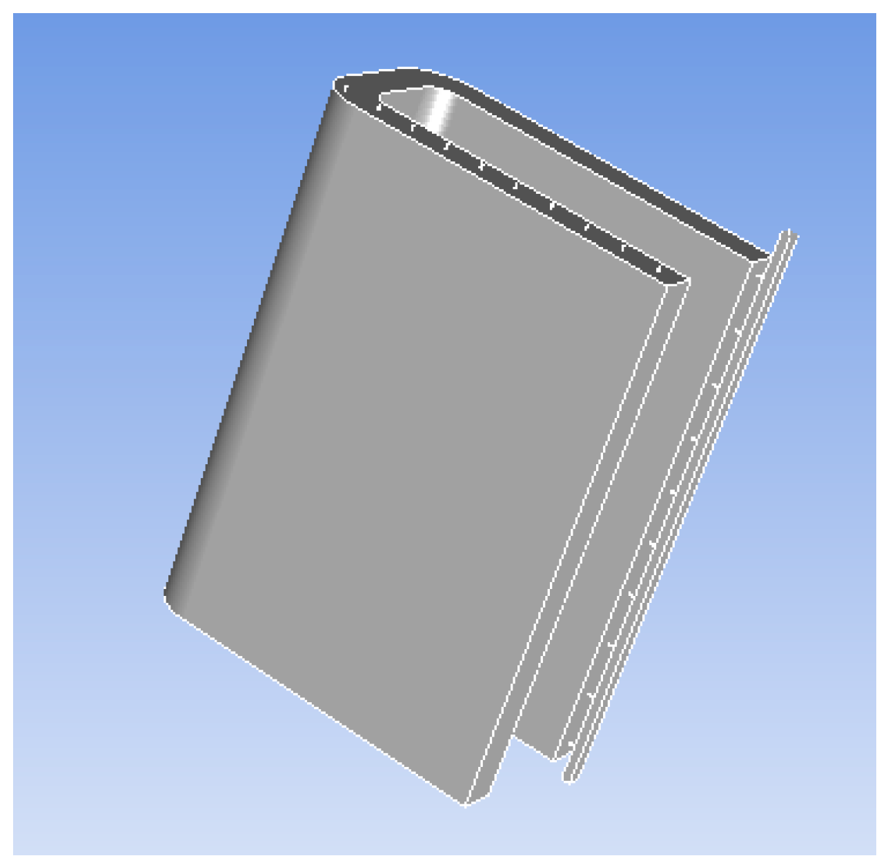
The pebble bed regions, which serve the purpose of breeding neutron and tritium, represent the most crucial structures of the Tritium Extraction System (TES). The pebbles, with a diameter of 1 mm, are installed randomly within the blue and green regions, with the U-shaped cooling plates arranged in close proximity to these regions.
Figure 2 depicts the three-dimensional view of a pebble bed region. The pebbles are arranged in a random manner. During the operation, the helium purge gas is forced into the blanket by the pump of the TES, and it passes the outside pebble bed region first. Subsequently, the purge gas flows into the inside pebble bed region, and after that, it goes outward toward the blanket. During the operation of the TES, the pressure at the outlet of the blanket is 0.3 MPa, and the flow rate of the TES purge gas is 0.125 g/s.
It is necessary to calculate the pressure drop of the blanket during the design process. The utilization of a traditional numerical simulation method to calculate the pressure drop would be prohibitively costly in terms of resources and time, thereby impeding the process. In the present era, the porous media is regarded as a suitable substitute for the pebble bed region in the analysis of pebble beds. There are two parameters that should be determined in the porous media: the permeability and the inertial loss coefficient. The purpose of this article is to investigate a method for determining the permeability (α) and inertial loss coefficient (C) of porous media based on the results obtained from simulations that employ the traditional numerical simulation method.
2.2. Methodology
2.2.1. The Obstacles and Effecting Factors in the Establishment of Model
The pressure drop gradient
is considered as the key indicator of the flow characteristics in the study of porous media. The pressure drop gradient
is believed to be related to the geometric parameters of the channels and the superficial velocity of the purge gas, as indicated by Darcy’s Equation (2). Consequently, the first task of this article is to construct a single-channel model with real pebbles installed (model A) to investigate these effects [
10].
where
α,
μ,
g,
and
ρ are the permeability of the porous media, the fluid viscosity, the gravity acceleration, the unit vector parallel to the gravity field and the fluid density, respectively [
10]. In this research, the single-channel model is regarded as a single horizontal channel in which the influence of gravity is assumed to be ignored. Therefore, the last term on the right side of the equation is assumed to be negligible.
Prior to the establishment of the model A, two obstacles must be considered. The first issue pertains to the simplification method of the contact between pebbles, and the second one concerns the arrangement of pebbles. Scholars at the SWIP have conducted numerous simulations of single-channel models with sequentially packed pebbles installed to identify appropriate methods for overcoming the aforementioned obstacles [
11].
With regard to the initial issue, three distinct methodologies have been employed worldwide, and all of them are depicted in
Figure 3 [
11]:
Method A involves shrinking the diameter of the balls to avoid the contact.
Method B involves cutting a section of the balls in the vicinity of the contact.
Method C involves constructing a small cylinder adjacent to the contact to increase the area.
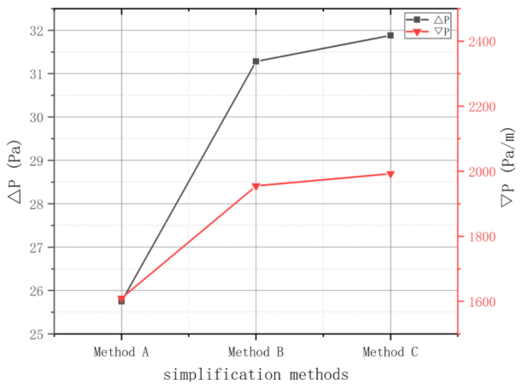
The scholars at the SWIP established models employing these methodologies with the utilization of the simple-cubic arrangement and calculated the pressure drop. It can be observed that Δ
P and
obtained using the last two simplification methods appear to be analogous, while Δ
P and
are lower in the first model. The results are illustrated in
Figure 4. Consequently, the third scheme is employed in this article with systematic consideration [
11].
The second problem is the arrangement of the pebbles. In the realistic scenario, the pebbles are packed randomly. As this paper is focused on determining the parameters of porous media, the pebbles are arranged in the channel in a sequential manner in order to simplify the model and conserve the calculation resources. Four arrangements are employed widely, namely simple cubic (SC), body-centered cubic (BCC), face-centered cubic (FCC) and hexagonal close-packed (HCP), as displayed in
Figure 5 [
11]. In contrast to the randomly packed pebble bed, the BCC approximates the porosity of the random pebble bed best among the proposed four packing configurations. Therefore, it is considered the optimal configuration for this simulation.
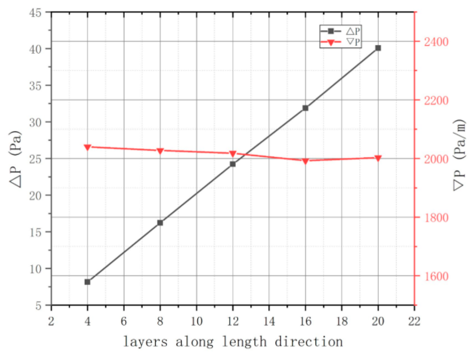
The geometry of the single channel may also influence the result, and it requires further investigation. The geometric parameters of the flow channel are the length and the width. In previous research, scholars at the SWIP constructed several models with distinct combinations of these parameters to analyze the effect, and the results are depicted in
Figure 6 and
Figure 7. As the number of layers along the length direction increases, Δ
P rises linearly and
undergoes minimal change. Moreover, the width of the pebble bed region exerts a slight influence on Δ
P and
. Consequently, the geometry of the channel is deemed to have no influence on
. The single-channel model is therefore regarded as suitable, provided that there are more than four layers along the length direction. This is consistent with the conclusions of other scholars [
12].
2.2.2. Proposed Methods for Determination
The permeability (
α in this paper) and the inertial loss coefficient (
C) are two parameters of the porous media that should be determined appropriately from the data obtained in the simulations of the single channel. Equation (3) illustrates that the pressure drop gradient (
is composed of the viscous loss term
and the inertial loss term
. Meanwhile,
and
are defined in Equations (4) and (5), respectively. It is evident that the calculation of α and C necessitates the division of ∇
Ptotal into two parts; however, this is a challenging task. Therefore, the correction method is proposed in which the permeability
α and inertial loss coefficient
C are calculated using
and subsequently modified in comparison. The scheme of this method is depicted in
Figure 8.
However, the loss coefficients are parameters that are solely related to the material and the porosity of the pebble bed region. Consequently, the loss coefficient should be constant for a specific pebble bed region. In this scenario, a method is proposed that assumes a second-order relationship between pressure drop and velocity. The relevant parameters are then calculated based on the results. The scheme of this method is illustrated in
Figure 9.
The efficacy of both methodologies would be evaluated in the subsequent chapters.
2.3. CFD Software
The commercial computational fluid dynamics (CFD) software ANSYS CFX is employed in this simulation. ANSYS CFX is a software that is widely used for CFD simulations and is considered suitable for this simulation. The ANSYS CFX solver employs a high-resolution method for the discretization of Navier–Stokes equations, simultaneously utilizing the finite volume method for solving the equations. In a typical case of CFX, three principal stages are involved: CFX-pre (pre-processing), CFX-solver (options and adjustments for solver) and CFX-post (post-processing of simulation results). The CFX-pre module requires the geometry model created in CAD software as an input data, after which the meshing process is completed. In the CFX-solver module, the appropriate settings suitable for solving the problems are adjusted, and the cases are solved. Ultimately, the patterns and data are depicted in the third module, CFX-post.
3. Parameters Determination
In this chapter, model A, referenced in chapter, 1 is established through the implementation of the BCC arrangement and the third simplification method previously outlined in
Section 2.2. Meanwhile, model B is constructed to evaluate the proposed methods. Based on model A, a series of simulations with distinct inlet superficial velocities are demonstrated, which will provide data for the determination of parameters. Two methods, the correction method and the fitting method, are utilized to determine the parameters of porous media, namely the permeability and the inertial loss coefficient. Both of the methodologies are then assessed with the employment of model B.
3.1. Simulation of Model A
As stated in the previous section, the superficial velocities of the purge gas in the blanket range from a fraction to more than 1 m/s due to the variation in the cross-section areas of the internal channels. Consequently, it is essential to calculate the occupations in the blanket against different velocities in order to determine the range of inlet velocities for the single-channel simulation. Scholars at the SWIP have demonstrated the requisite calculation, which has resulted in the division of the blanket into several sections with distinct velocities. The result is presented in
Table 2. Apparently, the occupations for low velocities are dominant, while the region with a velocity above 1 m/s is negligible. Based on the result, the inlet velocity of the single-channel model is considered to be within the range of 0.01 m/s to 1 m/s.
Model A is established based on the conclusions presented in
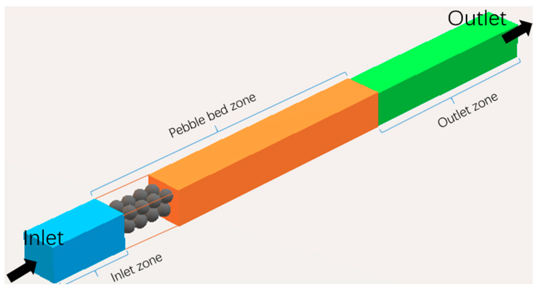
Section 2.2 and comprises the inlet/outlet domains and pebble bed region. To ensure the full development of the flow, the lengths of the inlet region and outlet region are given as five and ten times that of the diameter of pebble, respectively. The surface of the pebbles is considered to be a no-slip wall, while the other walls are considered to be symmetry boundaries, and the boundary layer effect is not considered. The pebbles are packed in BCC arrangement. Model A is depicted in
Figure 10.
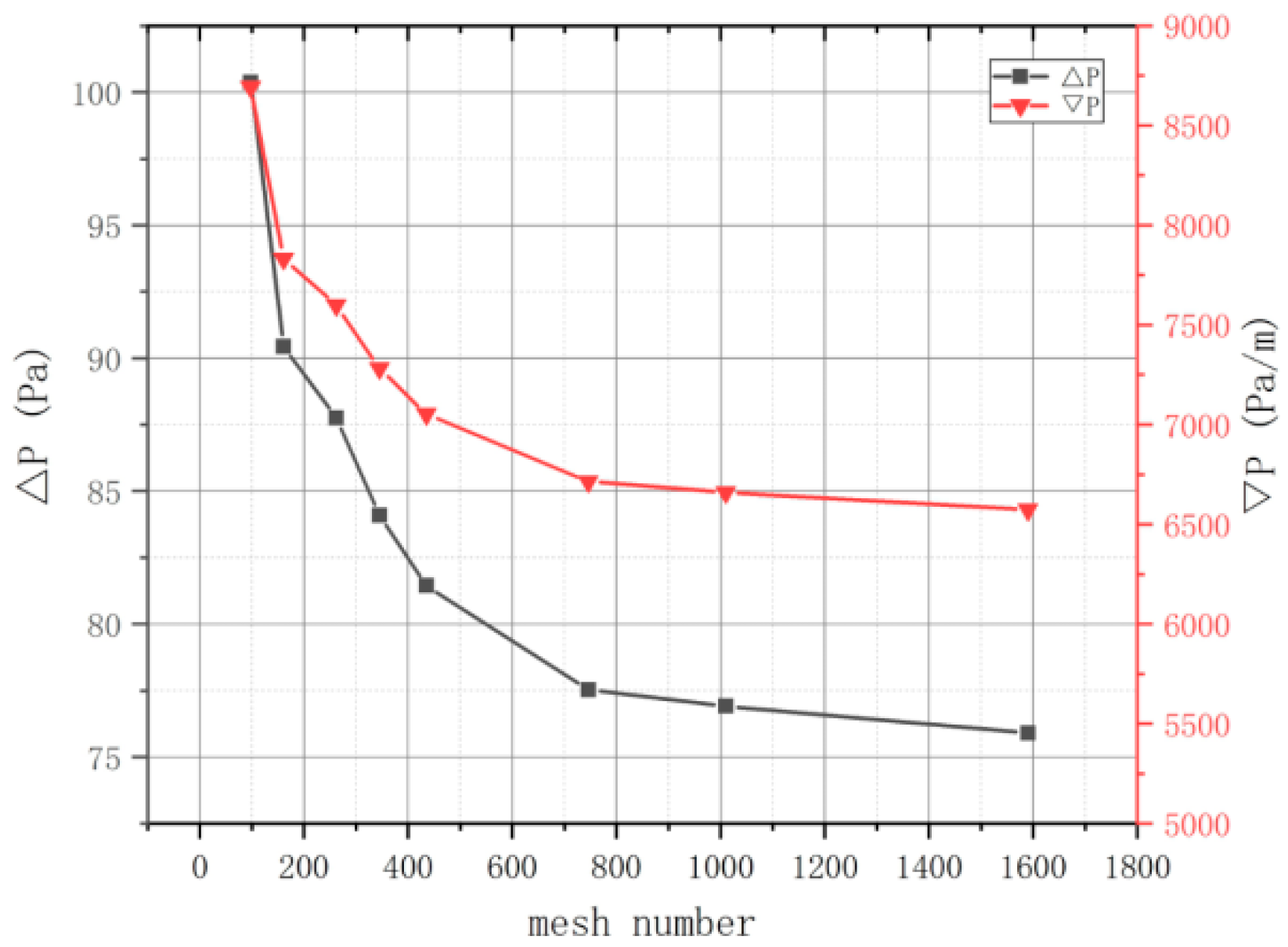
The result of a CFD simulation is found to be highly dependent on the number of mesh elements employed. To ascertain the mesh independence, six models were constructed and meshed into 0.98, 2.09, 4.35, 7.46, 10.1 and 15.9 million grids, respectively. The inlet boundary is defined as a velocity boundary, while the outlet boundary is designated as a static pressure type. The results depicted in
Figure 11 demonstrate that as the number of mesh elements increases, the pressure drop gradient declines, becoming increasingly smooth when the grid number exceeds 7.46 million. Furthermore, the difference in pressure drop is acceptable. Consequently, the model with 7.46 million mesh elements will be employed as model A in the following simulations.
In the simulations of model A, the inlet boundary of the model is considered as a velocity boundary with distinct velocities, while the outlet boundary is set as a relative pressure boundary with a pressure of 0.3 MPa. The result of the simulation is depicted in
Figure 12. It is found that the pressure drop Δ
P and its gradient
appear to be linearly proportional to the superficial velocities. This indicates that he second term (inertial loss term) is negligible in the low velocity range. The result is the provision for the determination process of parameters.
3.2. Correction Method
The data obtained in
Section 3.1 are utilized in this section to execute the correction method. The correction method is based on Darcy’s Equation (2), which allows the permeability (α) and loss coefficient (C) to be derived. The definitions are illustrated below:
where
v is the superficial velocity of the purge gas,
L is the length of the pebble bed region, and
[Pa] is the gradient of total pressure drop. In order to evaluate this method, model B, illustrated in chapter 1, is established.
The scheme of this method is shown in
Figure 8. The initial step is to calculate the estimated parameters,
α′ and
C′, which are then incorporated into model B to estimate ∇
P′. Following the comparison of
and
the coefficient
K (
K =
is calculated to modify these parameters, thereby yielding the new
and
C. Finally, the new
and
C are taken back into model B to calculate
.
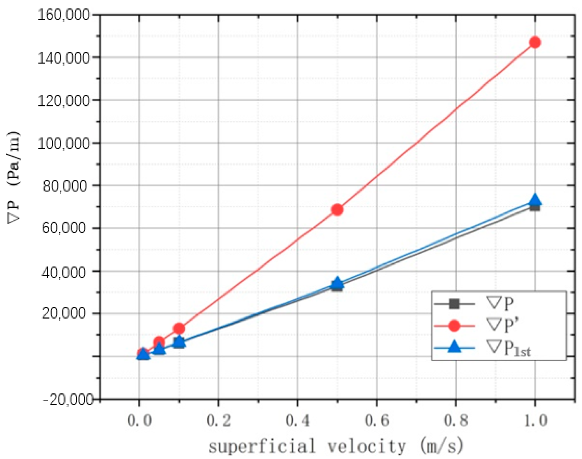
The results of the permeability and loss coefficient are presented in
Table 3, while the pressure drop gradient is illustrated in
Figure 13. It can be observed that
is considerably larger than
. This indicates that the parameters calculated using Equations (6) and (7) are not directly applicable. Since larger permeability and a lower loss coefficient are beneficial to the flow of the purge gas, the permeability and loss coefficient would be increased and decreased, respectively, employing the calculated coefficient
K. And after the modifications,
, which is the result in the correction method with one iteration, appears to be consistent with
, with a maximum relative error of 3.9%.
Furthermore, the new result could be obtained by implementing additional iterations in the correction method, as presented in
Table 4. It is evident that the maximum relative error decreases significantly from 3.9% to 0.6%. This demonstrates that the addition of iterations effectively minimizes the relative error in the correction method. In conclusion, the results indicate that the correction method is a feasible approach for determining the parameters for porous media.
3.3. Fitting Method
As previously stated in
Section 2.2, the parameters should be unrelated to the velocity. Therefore, the fitting method is proposed to obtain an independent set of parameters of porous media.
Research on porous media indicates that the pressure drop gradient (
is related to the superficial velocity with a second-order relationship. The pressure drop gradient is regarded a velocity-related source term in the momentum equation [
13]:
where
Si is the denote of the source term,
v is the velocity, and
D and
C are the coefficient matrices. The first term on the right side of the equation is the viscous resistance term and the second one is the inertial resistance term. In this article, it is assumed that the material of porous media is isotropic, which allows the equation to be simplified:
where
is the permeability and
C is the inertial loss coefficient. Consequently, the fitting method is utilized to obtain the relationship between
and velocity. The result is shown below:
Based on the result, the coefficients
and
C are calculated using Equation (9) and presented in
Table 5. A comparison of the parameters obtained using the two methods reveals that the permeability α is of a comparable magnitude. However, in the low velocity range, the loss coefficient
C obtained in the correction method is greater than that in the fitting method. In order to verify the rationality of the fitting method, the source term with an inertial resistance correction coefficient (
CF) is suggested [
14]:
Liu Xueqiang [
15] has recommended an equation to calculate
CF, and the Ergun equation could be employed to estimate this value. In Equation (13),
CF is related to the Reynolds number and the porosity of the material, while in Equation (14),
CF is related to the porosity alone. These equations are presented below:
where
Re is the Reynolds number and the
φ is the porosity. The results of the calculations are listed in
Table 6. It can be observed that
CF1 is consistently larger than
CF in all scenarios, and when the velocity exceeds 0.5 m/s, these two values become comparable. Conversely,
CF2 is similar with
CF throughout the velocity range. The difference can be attributed to the omission of the effect of Reynolds number in the Ergun equation and the fitting method equation.
It was observed that when α and C were introduced into model B, the simulation results were found to be comparable to those obtained in model A, with the relative errors remaining at around 6%. These findings are detailed in
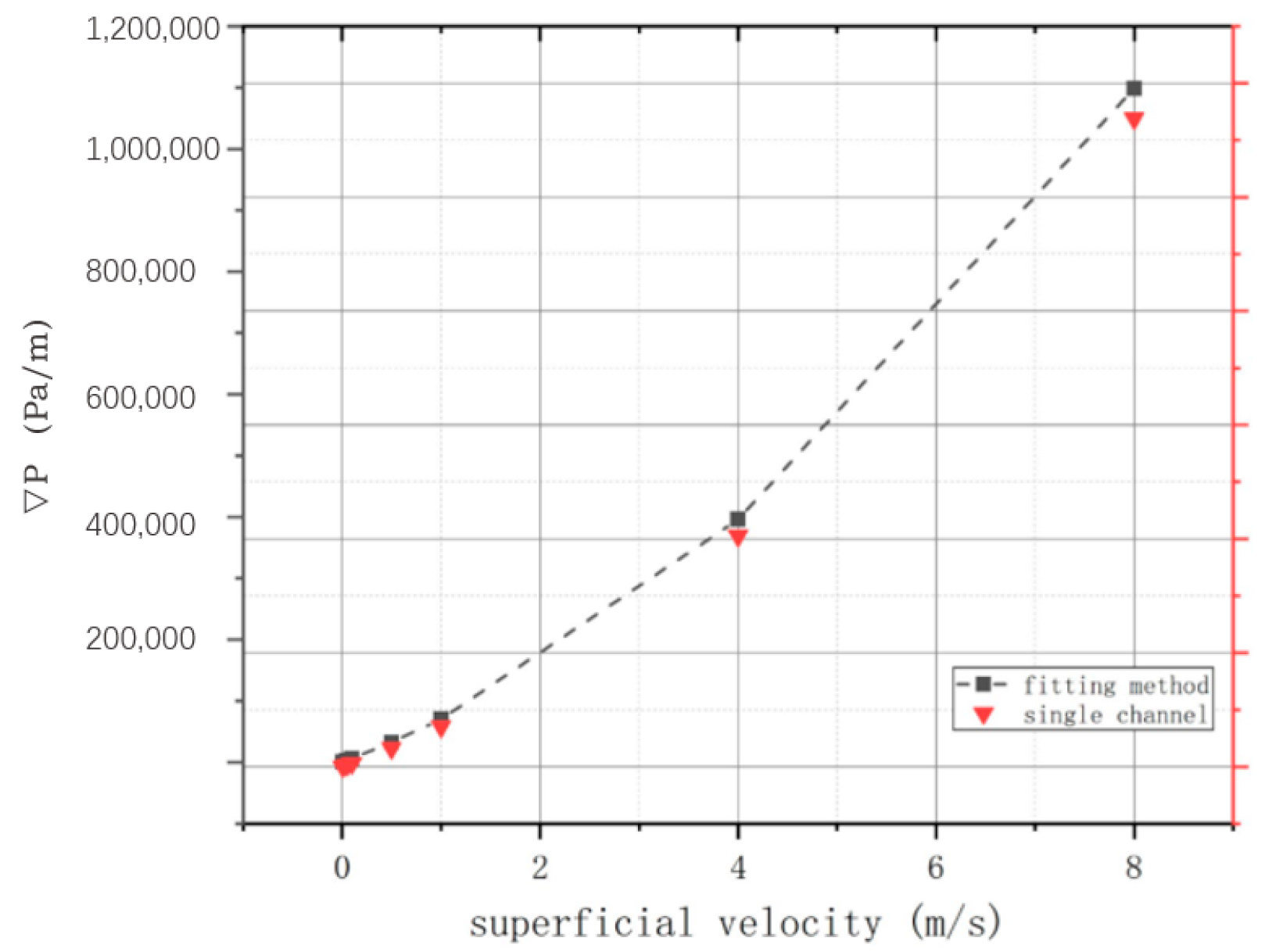
Table 7. Two scenarios with superficial velocities of 4 m/s and 8 m/s are calculated simultaneously to assess the correctness of the prediction of Equation (10), as displayed in
Figure 14. The results indicate that the equation is suitable, thereby supporting the feasibility behind the fitting method for determining parameters in porous media.
4. Holistic Hydraulic Simulation for Blanket
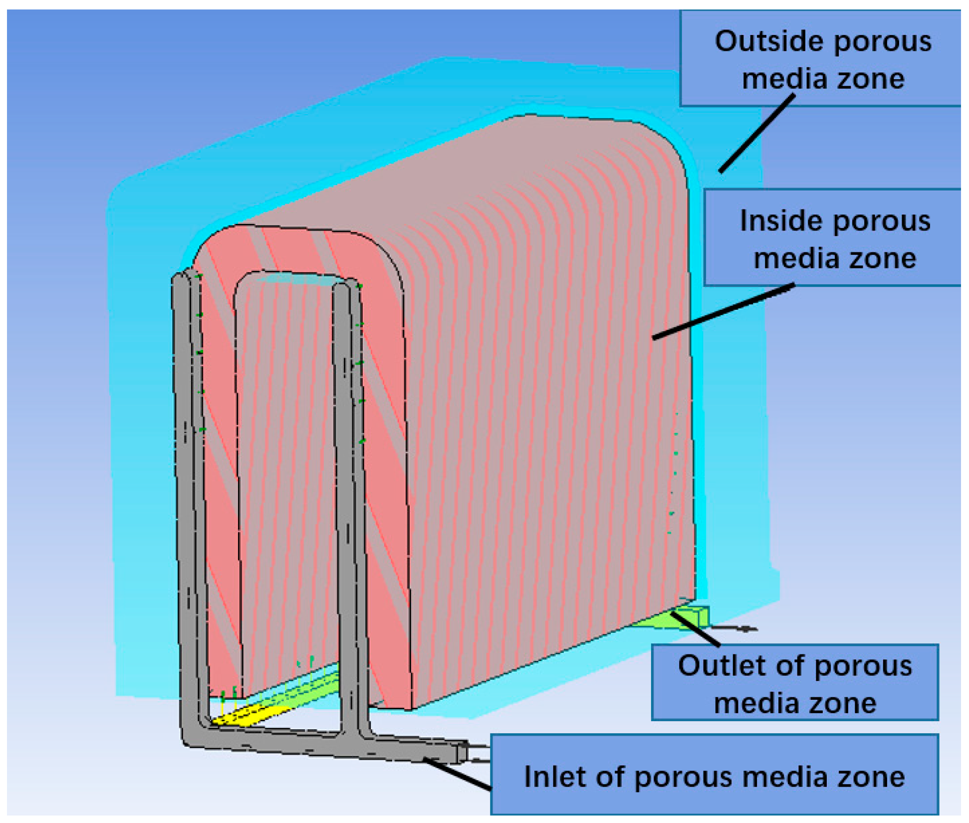
The utilization of the porous media in a realistic model of engineering is emphasized in this paper; thus, a holistic model of blanket should be established. The blanket module comprises two symmetry parts and thus one of them is considered as the objective in this section and is displayed in
Figure 15. The holistic model consists of one inlet pipe, one outlet pipe and the internal and external porous media zones.
The parameters obtained in the correction method are related to the superficial velocity of the coolant. Therefore, it is necessary to divide the holistic model into several parts with distinct superficial velocities. In order to accurately capture the flow characteristics in the low velocity distribution and calculate the pressure drop, the size of the mesh elements in the low velocity regions is reduced. This results in a holistic model with 18.23 million meshes. In the simulation employing parameters obtained using fitting method, the blanket is meshed into 5.9 million elements. Both the results in these models are verified as grid-independent solutions.
In the simulation of the holistic model, the inlet boundary is considered to be of the static mass flow rate type, with a helium flow rate of 0.125 g/s. The outlet boundary is set as a relative pressure boundary with 0.3 MPa. For the porous media, the parameters obtained in the correction method and the fitting method are used.
With the incorporation of the permeability and the inertial loss coefficient into the holistic model, the overall pressure drop and the distributions of velocity and pressure in both the internal and external porous media regions are calculated and analyzed. As the velocity and pressure distributions are similar in both models, the distributions and streamline of the model employing the fitting method are depicted.
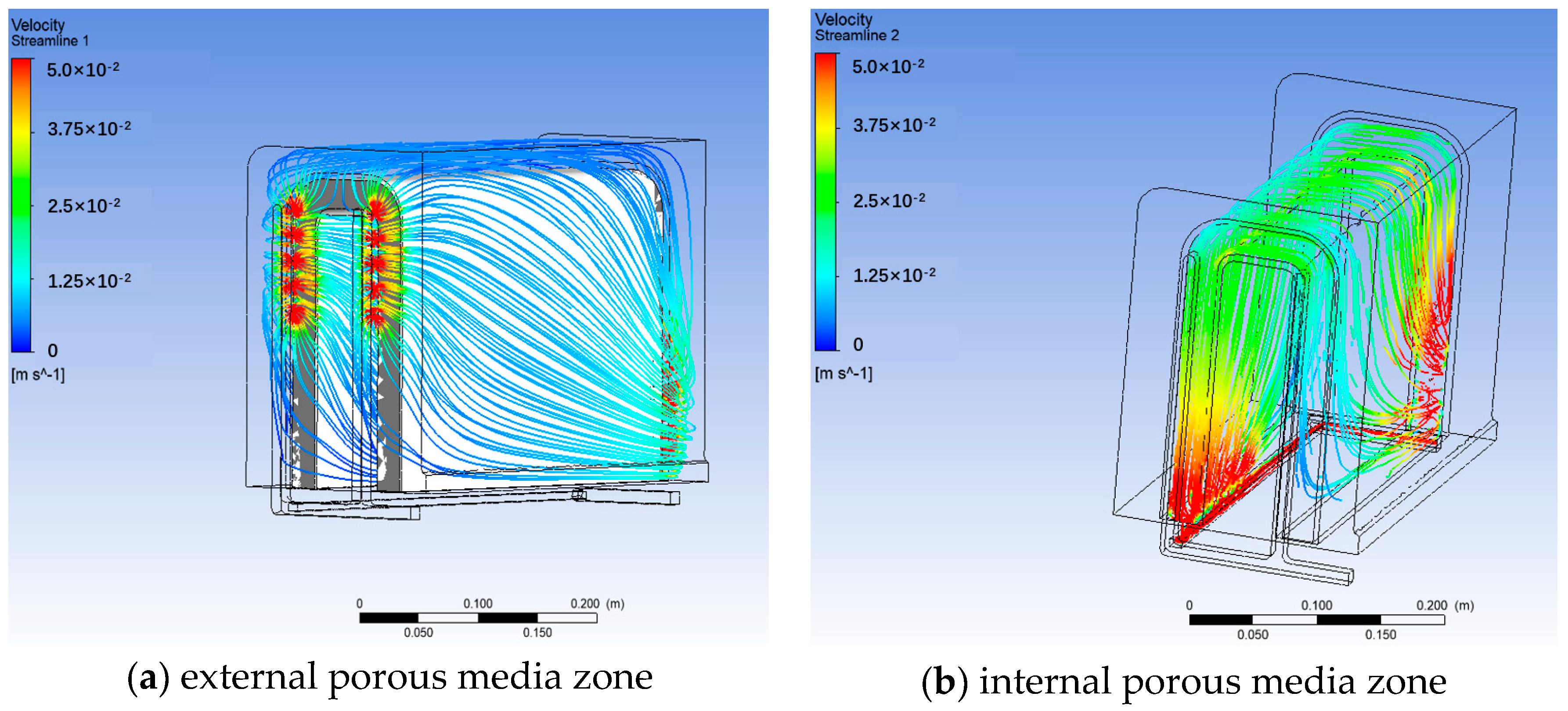
The streamlines of purge gas in the external and internal porous media region are depicted in
Figure 16a and
Figure 16b, respectively. It can be observed that the velocity of the purge gas decreases rapidly while entering the porous media region from the inlet pipe. It then flows inside the external region towards the rear small tubes. The whole process of the flow remains continuous and smooth, and no dead region could be seen. In the internal porous media region, the streamline is similar, exhibiting only slight differences in average velocity. The purge gas flows at a higher velocity in the internal region due to the smaller area of the cross-section of the internal region. Ultimately, the purge gas gathers at the outlet of the internal region and flows outwards.
The velocity nephograms in porous media are illustrated in
Figure 17a,b. It is evident that the velocity distribution in the external region is relatively stable, with low velocity. However, there is a low-velocity region in the internal region (blue region in
Figure 17b). This region may result in the concentration of the tritium in the corners that are not adjacent the inlet and outlet pipes, which could potentially lead to tritium permeation. Therefore, it is essential to consider this phenomenon when calculating the tritium permeation.
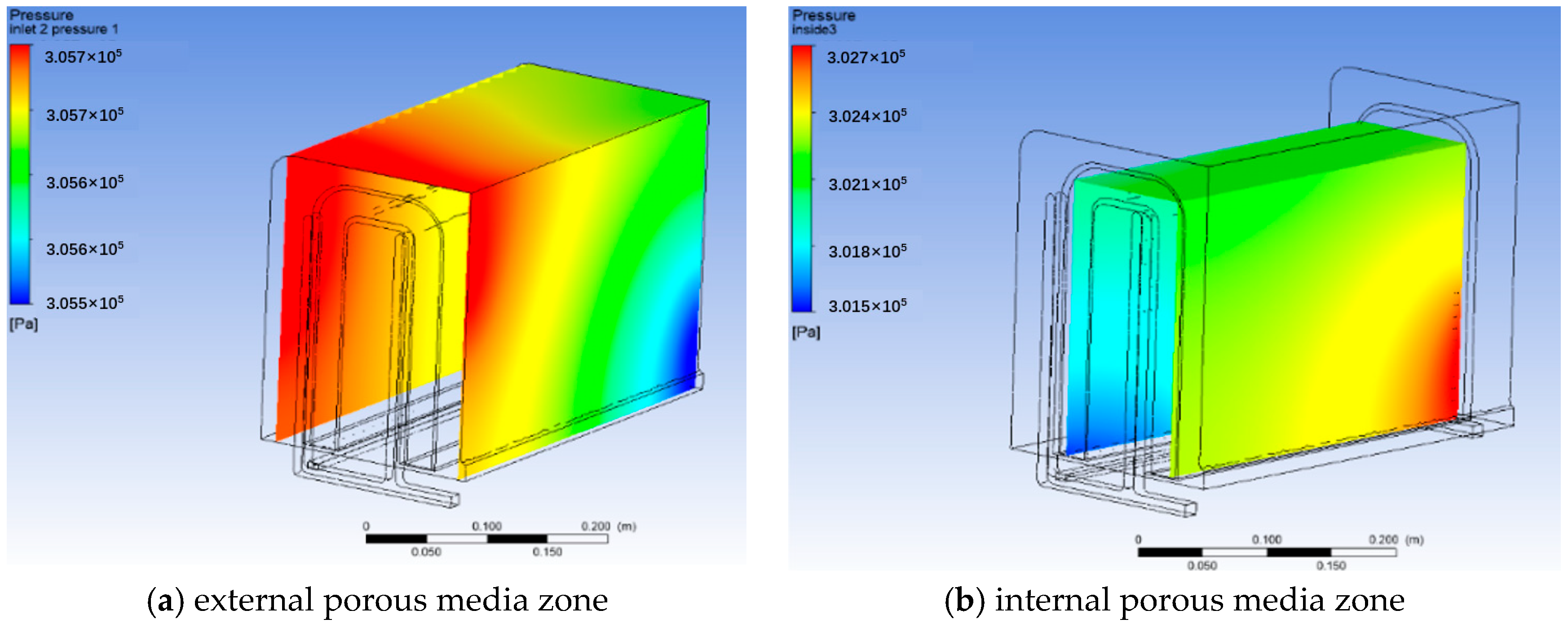
Figure 18 depicts the pressure distributions in the external and internal regions. The pressure in both regions exhibits a mild distribution and a descending tendency along the flow route. There is no evidence of a high-/low-pressure zone in the corner or boundary of the porous media region. The simulation with porous media approach is consistent with the realistic phenomenon.
The overall pressure drop is 2571 Pa and 2515 Pa in the scenarios with parameters obtained using the correction method and fitting method, respectively. The difference between the results can be attributed to the approaches for the parameter determinations. In the correction method, the parameters are related to the superficial velocity, whereas in the fitting method, they are regarded as constants. Nevertheless, the discrepancy of them is only 2.2% and could be accepted. The simulation using the correction method requires distinct mesh distributions and a larger number of meshes, which would require a tremendous amount of calculating resources and time. Therefore, the simulation using the fitting method is suggested for the preliminary design phase by authors. Furthermore, once the design has been completed, the correction method with necessary iterations is recommended to acquire accurate results.
5. Conclusions
In this paper, the determination process of the parameters for porous media and the holistic hydraulic simulation for a helium-cooled blanket are emphasized. A single-channel model with pebbles sequentially packed inside (model A) is established to calculate the pressure drop gradient, P, against superficial velocity, to provide data for the determination process. In addition, a comparable single-channel model with porous media (model B) is constructed to assess the efficacy of two proposed methodologies: the correction method and fitting method. Finally, the overall pressure drop of the holistic blanket model is calculated to in order to assess the utility of these methods.
The following conclusions are obtained:
The results in
Section 3.1 indicate that the pressure drop gradient is more likely to be related to the superficial velocity of the purge gas with a linear relationship in the low velocity range. This phenomenon can be attributed to the fact that the second-order term is negligible in the low velocity range.
Results obtained from the correction method and fitting method match well with that in model A. However, there are some differences between the two methods. In the correction method, the parameters are related to the superficial velocity, whereas in the fitting method, they are regarded as constants.
The overall pressure drops of the holistic model using parameters obtained from two methods are comparable with a relative error of 3.9%. This indicates that both of the methods are feasible in this particular utilization.
Given that the correction method necessitates a more substantial grid density and a considerable amount of simulation to provide data, the fitting method is suggested in the preliminary design phase by the authors to impel the process. Following the completion of the design phase, the correction method with necessary iterations is recommended to obtain precise results.
The subsequent stage of this research is to measure the pressure drop gradient of the randomly packed pebble bed with the experimental method, with the objective of determining the permeability and inertial loss coefficient.
Author Contributions
Writing-original raft, formal analysis, data curation, B.H.; Methodology, review & editing, validation, B.Z.; Funding acquisition, Resources, S.B.; Methodology, Resources, Software, X.W.; Review & editing, investigation, B.G. All authors have read and agreed to the published version of the manuscript.
Funding
This work was funded by the National Natural Science Foundation of China (No. 52276052).
Data Availability Statement
The data presented in this study are available on request from the corresponding author due to that the data is related to an internal project.
Acknowledgments
This work was supported by the SWIP TBM team.
Conflicts of Interest
The authors declare no conflict of interests.
References
- Hubbert, M.K. Darcy’s law and the field equations of the flow of underground fluids. Trans. AIME 1956, 207, 222–239. [Google Scholar] [CrossRef]
- Kueper, B.H.; Frind, E.O. Two-phase Flow in Heterogeneous Porous Media 2. Model Application. Water Resour. Res. 1991, 27, 1059–1070. [Google Scholar] [CrossRef]
- Firoozabadi, A.; Katz, D.L. An analysis of High-velocity Gas Flow Through Porous Media. J. Pet. Technol. 1979, 31, 210–216. [Google Scholar] [CrossRef]
- Allan, F.M.; Hajji, M.A.; Anwar, M.N. The characteristics of fluid flow through multilayer porous media. J. Appl. Mech. 2009, 76, 014501. [Google Scholar] [CrossRef]
- Li, L.; Yuan, H.; Wang, K. The Modelling and Coupling Methodology of ANSYS CFX Using Porous Media for PB-AHTR. In Proceedings of the International Conference on Nuclear Engineering, Chengdu, China, 29 July–2 August 2013; American Society of Mechanical Engineers: New York, NY, USA, 2013; Volume 55805. [Google Scholar]
- Wang, X.Y.; Feng, K.M.; Chen, Y.J.; Zhang, L.; Feng, Y.J.; Wu, X.H.; Liao, H.B.; Ye, X.F.; Zhao, F.C.; Cao, Q.X. Current design and R&D progress of the Chinese helium cooled ceramic breeder test blanket system. Nucl. Fusion 2019, 59, 076019. [Google Scholar]
- Wang, M.; Liu, D.; Xiang, Y.; Cui, S.; Su, G.H.; Qiu, S.; Tian, W. Experimental study of the helium flow characteristics in pebble-bed under the condition of CFETR’s blanket module. Prog. Nucl. Energy 2017, 100, 283–291. [Google Scholar] [CrossRef]
- Desu, R.K.; Chaudhuri, P.; Annabattula, R.K. High temperature oedometric compression of Li2TiO3 pebble beds for Indian TBM. Fusion Eng. Des. 2018, 136, 945–949. [Google Scholar] [CrossRef]
- Zhou, B.; Feng, Y.; Wang, X.; Wu, X. Study of equivalent heat conductivity in the Li4SiO4 Pebble Bed. Nucl. Fusion Plasma Phys. 2018, 38, 99–104. [Google Scholar]
- Huinink, H. Fluids in Porous Media-Transport and Phase Changes; Morgan & Claypool Publishers: San Rafael, CA, USA, 2016. [Google Scholar]
- Zhou, B.; Wu, X.H. Analyses of flow characteristic and heat transfer of helium coolant in TBM sub-module. In Proceedings of the the 2022 Annual Seminar of TBM Team, Chengdu, China, December 2022. [Google Scholar]
- Li, J.; Song, X.; Lu, J.; Li, Z. Scaling effect on Flow Characteristics of a Structured Packed Bed Using CFD Method. Nucl. Power Eng. 2013, 25–29. [Google Scholar]
- ANASYS Fluent User’s Guide Volume 1-7.2.3 Porous Media Conditions. Available online: https://www.afs.enea.it/project/neptunius/docs/fluent/html/ug/node233.htm (accessed on 20 January 2024).
- Yu, L.; Sun, L.; Sun, Z. Numerical Simulation of Single-Flow Resistance in Porous Media Channel. At. Sci. Technol. 2010, 44, 1441–1444. [Google Scholar]
- Zhang, Z.; Liu, X.; Yan, X.; Xiao, Z. Numerical study on resistance characteristics of single-phase flow through porous media. Nucl. Power Eng. 2009, 30, 91–94. [Google Scholar]
Figure 1.
Configuration of tritium breeding blanket.
Figure 1.
Configuration of tritium breeding blanket.
Figure 2.
A 3D view of pebble bed region.
Figure 2.
A 3D view of pebble bed region.
Figure 3.
Scheme of simplifications for contacts of pebbles [
11].
Figure 3.
Scheme of simplifications for contacts of pebbles [
11].
Figure 4.
Pressure drop ΔP and its gradient in different simplification methods using SC arrangement.
Figure 4.
Pressure drop ΔP and its gradient in different simplification methods using SC arrangement.
Figure 5.
General layout of four arrangements [
11].
Figure 5.
General layout of four arrangements [
11].
Figure 6.
ΔP and against length.
Figure 6.
ΔP and against length.
Figure 7.
ΔP and against width.
Figure 7.
ΔP and against width.
Figure 8.
Scheme of correction method.
Figure 8.
Scheme of correction method.
Figure 9.
The scheme of the fitting method.
Figure 9.
The scheme of the fitting method.
Figure 10.
Layout of MODEL A.
Figure 10.
Layout of MODEL A.
Figure 11.
Pressure drop ΔP and its gradient against mesh number.
Figure 11.
Pressure drop ΔP and its gradient against mesh number.
Figure 12.
ΔP and against superficial velocities.
Figure 12.
ΔP and against superficial velocities.
Figure 13.
against superficial velocity.
Figure 13.
against superficial velocity.
Figure 14.
in fitting method.
Figure 14.
in fitting method.
Figure 15.
Symmetry model.
Figure 15.
Symmetry model.
Figure 16.
Streamline in porous media.
Figure 16.
Streamline in porous media.
Figure 17.
Velocity nephograms.
Figure 17.
Velocity nephograms.
Figure 18.
Pressure distributions in porous media.
Figure 18.
Pressure distributions in porous media.
Table 1.
The nomenclature of models.
Table 1.
The nomenclature of models.
| Model Name | Interpretation |
|---|
| Model A | A single rectangular channel model installed with sequentially packed pebbles. The body-centered cubic (BCC) arrangement and the third simplification method (illustrated in Section 2.2) are employed. |
| Model B | A single rectangular channel model installed with porous media. The geometric parameters are consistent with model A. |
Table 2.
Volume occupations against velocity.
Table 2.
Volume occupations against velocity.
| Parameters | Section 1 | Section 2 | Section 3 | Section 4 | Section 5 | Section 6 |
|---|
| Velocity (m/s) | <0.02 | 0.02~0.03 | 0.03~0.05 | 0.05~0.1 | 0.1~1.0 | 1.0~10 |
| Volume (m3) | 1.45 × 10⁻² | 1.80 × 10⁻³ | 6.97 × 10⁻⁴ | 1.44 × 10⁻⁴ | 2.21 × 10⁻⁵ | 3.96 × 10⁻⁶ |
| Occupation (%) | 84.405 | 10.533 | 4.069 | 0.840 | 0.129 | 0.023 |
Table 3.
Results using correction method.
Table 3.
Results using correction method.
V
(m/s) |
(m2) | C′
(m−1) |
|
| K |
(m2) | C
(m−1) |
(Pa/m) |
|---|
| 0.01 | 4.912 × 10⁻¹⁰ | 4.965 × 10⁷ | 625.2 | 1245.3 | 1.992 | 9.8 × 10⁻¹⁰ | 2.5 × 10⁷ | 622.7 |
| 0.05 | 4.955 × 10⁻¹⁰ | 9.845 × 10⁶ | 3098.7 | 6473.5 | 2.089 | 1.03 × 10⁻⁹ | 4.7 × 10⁶ | 3195.6 |
| 0.1 | 4.926 × 10⁻¹⁰ | 4.95 × 10⁶ | 6232.8 | 12,990.4 | 2.084 | 1.03 × 10⁻⁹ | 2.4 × 10⁶ | 6477.9 |
| 0.5 | 4.683 × 10⁻¹⁰ | 1.042 × 10⁶ | 32,786.8 | 68,571.9 | 2.091 | 9.8 × 10⁻¹⁰ | 4.9 × 10⁵ | 33,948.2 |
| 1.0 | 4.361 × 10⁻¹⁰ | 5.593 × 10⁵ | 70,415.7 | 147,051.2 | 2.088 | 9.1 × 10⁻¹⁰ | 2.7 × 10⁵ | 72,832.8 |
Table 4.
Relative errors in first iteration and second iteration.
Table 4.
Relative errors in first iteration and second iteration.
V
(m/s) |
|
(Pa/m) |
(Pa/m) | Relative Error (1st Iteration) | Relative Error (2nd Iteration) |
|---|
| 0.01 | 625.20 | 622.70 | 627.87 | 0.41% | 0.42% |
| 0.05 | 3098.70 | 3195.60 | 3090.85 | 3.1% | 0.25% |
| 0.1 | 6232.80 | 6477.90 | 6257.04 | 3.9% | 0.39% |
| 0.5 | 32,786.80 | 33,948.00 | 32,638.78 | 3.5% | 0.45% |
| 1.0 | 70,415.70 | 72,832.80 | 70,838.31 | 3.4% | 0.60% |
Table 5.
Parameters in porous media.
Table 5.
Parameters in porous media.
| Velocity | Fitting Method | Correction Method |
|---|
| α (m2) | C (m−1) | α (m2) | C (m−1) |
|---|
| 0.01 | 5.05 × 10⁻¹⁰ | 75,891 | 9.8 × 10⁻¹⁰ | 2.5 × 10⁷ |
| 0.05 | 1.03 × 10⁻⁹ | 4.7 × 10⁶ |
| 0.1 | 1.03 × 10⁻⁹ | 2.4 × 10⁶ |
| 0.5 | 9.8 × 10⁻¹⁰ | 4.9 × 10⁵ |
| 1.0 | 9.1 × 10⁻¹⁰ | 2.7 × 10⁵ |
Table 6.
Comparison of CF.
Table 6.
Comparison of CF.
| Velocity | CF (Fitting Method) | CF (Equation (13)) | CF (Equation (14)) |
|---|
| 0.01 | 0.8524 | 2.2518 | 0.7212 |
| 0.05 | 1.6320 |
| 0.1 | 1.4208 |
| 0.5 | 1.0297 |
| 1.0 | 0.8964 |
Table 7.
Pressure drop in porous media.
Table 7.
Pressure drop in porous media.
| Velocity (m/s) | P in Porous Media (Pa) | P in Real Model (Pa) | Relative Error |
|---|
| 0.01 | 662.5 | 625.2 | 5.6% |
| 0.05 | 3317.7 | 3098.7 | 6.6% |
| 0.1 | 6584.4 | 6232.8 | 5.3% |
| 0.5 | 35,048.1 | 32,786.8 | 6.5% |
| 1.0 | 75,371.9 | 70,415.7 | 6.6% |
| Disclaimer/Publisher’s Note: The statements, opinions and data contained in all publications are solely those of the individual author(s) and contributor(s) and not of MDPI and/or the editor(s). MDPI and/or the editor(s) disclaim responsibility for any injury to people or property resulting from any ideas, methods, instructions or products referred to in the content. |
© 2024 by the authors. Licensee MDPI, Basel, Switzerland. This article is an open access article distributed under the terms and conditions of the Creative Commons Attribution (CC BY) license (https://creativecommons.org/licenses/by/4.0/).

