Article

Research on the Design of a MIMO Management System for Lithium-Ion Batteries Based on Radiation–Conductivity–Convection Coupled Thermal Analysis

1
School of Automation and Software Engineering, Shanxi University, Taiyuan 030006, China
2
National Engineering Laboratory of Big Data Analytics and Application Technology, Peking University, Beijing 100871, China
*
Author to whom correspondence should be addressed.
Energies 2024, 17(14), 3504; https://doi.org/10.3390/en17143504
Submission received: 18 June 2024 / Revised: 6 July 2024 / Accepted: 10 July 2024 / Published: 17 July 2024
(This article belongs to the Section D: Energy Storage and Application)

Abstract

:
In this study, the heat transfer model of a radiation–conduction–convection coupled lithium-ion battery pack is established through theoretical analysis. The temperature distribution and flow field distribution inside the battery pack are obtained by simulation using ANSYS Fluent software 2022 R1, and the reasonableness of the simulation model is verified with an experiment. This study also analyzes in detail the improvement effect of adding heat dissipation ribs, applying heat dissipation coatings, and adjusting the fan speed on the heat dissipation performance of the system. Under the same heat sink rib height conditions, the relationship between its thickness and total heat dissipation and thermal efficiency is studied in depth, and the temperature distribution of the cell under different rib thicknesses is obtained. At the same time, the emissivity of the heat sink coating under different coating thicknesses was measured by infrared thermography, and the relevant design values were determined through simulation experiments. Finally, based on the experimental test results of fan performance, a corresponding control strategy is proposed to construct an efficient and high-performance multiple-input multiple-output (MIMO) battery thermal management system. The experimental results show that optimizing the structure of the forced air cooling system through the above measures can ensure that the Li-ion battery operates within the efficient operating temperature range, thus extending its cycle life, improving its stability, and reducing the risk of thermal runaway. Meanwhile, the problem of excessive temperature difference between different modules is improved, and the output capacity of the energy storage system is increased.

1. Introduction

With the continuous growth of global energy demand and the intensification of environmental issues, the promotion of renewable energy has become crucial to achieving sustainable development goals. In this context, energy storage technology, as the cornerstone of energy transition and renewable energy integration, has received considerable research and attention. This technology is widely used in various fields, including electric transportation, renewable energy storage, grid regulation, and portable electronic devices [1]. Lithium-ion storage batteries play a significant role in the energy storage sector due to their high energy density, light weight, long lifespan, and low self-discharge. However, in long-term use, Li-ion batteries face numerous challenges, especially temperature management [2,3,4]. The performance and lifespan of lithium-ion batteries are significantly affected by temperature. At excessively high or low temperatures, battery conductivity and internal resistance can change significantly, resulting in greatly reduced battery power and cycling. Therefore, temperature management is key to improving the performance and lifetime of lithium-ion batteries. Effective cooling technology can keep the temperature of the energy storage system in a suitable range and prevent overheating from damaging the system’s performance and lifetime [5,6,7]. Currently, the mainstream methods of battery thermal management are air cooling and liquid cooling. Although liquid-cooled systems have the advantages of efficient heat dissipation performance, flexible space layout, and low operating noise [8,9,10,11,12,13,14,15], air-cooled systems are often preferred in many applications due to their simple structure, low cost, and easy maintenance [16,17,18,19,20,21,22,23,24,25,26].
In recent years, extensive research has been conducted by both domestic and international scholars in the field of air-cooled battery thermal management, with significant achievements particularly in natural air-cooled heat dissipation structures. Xu et al. [16] investigated the effects of different air vent sizes and ambient temperatures on the natural air-cooled performance of lithium-ion batteries through numerical simulation. They found that when the air vent size is similar to the outlet size and the ambient temperature is lower, the battery cooling performance is enhanced. Liu et al. [17] designed and established a natural air-cooled model of the lithium-ion battery pack with the same arrangement of inlet and outlet ports. They also simulated predictions of temperature rises and temperature differences in battery packs. It was shown that the temperature uniformity of the battery pack can be significantly improved by reducing the charging and discharging multiplicity or increasing the surface convective heat transfer coefficient. Li et al. [18] identified local optimal solutions through a multi-objective optimization study based on orthogonal experiments, focusing on the inlet angle, outlet angle, and battery spacing. Yang et al. [19] designed a natural air cooling model with differently oriented air inlets and outlets for a specific container battery module, analyzing its thermal performance. They discovered that increasing the width and arrangement angle of the deflector could lower the maximum and average temperatures of the battery cooling surface. Huang et al. [20] compared the cooling performance of battery packs at different discharge rates under natural cooling and concluded that natural cooling is no longer suitable when the battery operates at a high multiple rate.
The main advantages of natural air cooling include its simplicity and cost-effectiveness. This cooling method does not rely on external mechanical equipment, resulting in lower operational and maintenance costs, and it is also more eco-friendly. It is suitable for environments with low heat output or strict noise requirements. However, when the heat generated by the equipment is substantial or operates in high-temperature environments, the efficiency of natural air cooling may not be able to meet the heat dissipation requirements. At this point, the choice of forced air cooling becomes especially important. By accelerating the airflow through the fan, forced air cooling significantly improves the heat dissipation efficiency, which can effectively control the temperature of the equipment and ensure the stable operation under high load working conditions. Mahamud et al. [21] proposed a novel battery thermal management method utilizing circulating airflow cooling. By using a multi-channel structure and reversible valves with a blower to achieve two-way airflow in the lithium-ion battery pack, the performance of the cooling system was effectively improved. Fan et al. [22] used CFD technology to simulate and analyze the specific effects of the battery gap size and air inlet volume on the temperature distribution of the battery pack, and found that increasing the inlet flow rate could reduce the maximum temperature of the battery pack. Although increasing the battery gap increases the surface temperature of the battery, the temperature distribution is more uniform. Park et al. [23] designed a conical deflector structure. Based on the U-shaped deflector, the inlet and outlet ports are extended vertically in a linear direction, which realizes the system’s depressurization and ventilation. Yang et al. [24] researched the air-cooled thermal management system of cylindrical lithium-ion batteries and explored the influence of the radial spacing of the monomers on the cooling effect. The results show that increasing the spacing can significantly improve the uniformity of temperature distribution and reduce the power cost of the cooling system, although the average temperature increases slightly. Lui et al. [25] designed a forced air cooling system for lithium-ion battery packs. The airflow is regulated by fans and baffles, and the air outlet is realized by combining the long holes on both sides and the round holes on the back. Simulation shows that this design substantially improves the heat dissipation performance. Liu et al. [26] investigated the effects of air duct structure and battery cell spacing on the heat dissipation effect by establishing the pressure loss equation. An improved design of a wave-shaped battery pack was proposed.
After the literature review, it was found that natural air cooling technology for batteries is relatively mature, but there are still some application limitations. Forced air cooling technology can make up for its defects to a certain extent, so it has great potential for application. However, in practice, it has been found that different modules tend to have uneven heat dissipation. Current battery module fans only control start/stop and run at a constant high speed, which can easily cause problems. On one hand, compared to the battery module close to the outlet of industrial air conditioning, the temperature of the batteries in the remote module is generally higher. The temperature difference between different modules is too large, which will affect the overall performance of the energy storage system, especially in the need for high-current discharge, the output capacity of the entire energy storage system will be greatly reduced, and if some of the core temperatures are too high for a long time, there will be a chain reaction leading to heat buildup. In severe cases, thermal runaway occurs, causing a series of irreversible consequences. On the other hand, if the fan speed is designed too high, it will lead to faster wear and tear of the internal machinery, increase noise and vibration, reduce the performance and service life of the fan, and at the same time greatly increase the energy consumption and safety risks. In this study, a forced air cooling system was optimized, and a heat transfer model of lithium-ion battery pack with radiation–conduction–convection coupling was established to explore the relationship between the thickness of heat dissipation ribs and the total heat dissipation as well as the total heat dissipation efficiency, which in turn affects the cooling effect. We also explore the relationship between the thickness of the heat sink coating and emissivity as well as the effect of increasing wind speed on the temperature of the battery pack. Based on the optimization measures, a new control strategy is proposed. With a MIMO control system as the core, the fan speeds of different modules are controlled according to the temperature of the battery cells so as to ensure the balanced heat dissipation of different modules and realize the high efficiency and performance of the system.

2. Radiation–Conduction–Convection Coupled Model for Lithium-Ion Battery Packs

2.1. Battery Pack Mathematical Model

Under steady-state conditions, with either natural or forced convection, and without considering the mass transfer of multi-component fluids, convective heat transfer can be described by a set of differential equations. These equations include the conservation of mass (continuity equation), conservation of momentum, and conservation of energy.
According to the principle of mass conservation, the difference between the mass flow rate entering and leaving a control volume equals the rate of change of mass within that control volume over time. This principle leads to the derivation of the mass conservation equation for incompressible fluids, known as the continuity equation. This is shown as follows,
ρ t + ( ρ u ) x + ( ρ v ) y + ( ρ w ) z = 0
In any infinitesimal control volume within a fluid, the sum of all external forces acting on that volume equals the rate of change of fluid momentum within the control volume. These external forces include surface forces and body forces. Based on this conservation principle, the differential equations for momentum conservation of the three velocity components can be derived.
u t + d i v ( u U ) = d i v ( v gard u ) 1 ρ p x v t + d i v ( v U ) = d i v ( v gard v ) 1 ρ p y w t + d i v ( w U ) = d i v ( v gard w ) 1 ρ p z
The total heat imported by thermal convection and net conduction through the boundary surfaces of a control volume per unit time, plus the work done by various forces acting on the fluid at the interface per unit time, equals the change rate of the total energy of the fluid within the control volume. This leads to the energy conservation equation,
ρ c p T t + u · T = · ( k T ) · ( ρ u C P T ) + · q r a d + Q
where ρ is the fluid density, c p is the specific heat capacity at constant pressure, T is the temperature, t is the time, u is the velocity vector, k is the thermal conductivity, · ( k T ) represents the conduction term, · ( ρ u C P T ) represents the convection term, · q r a d represents the radiation term, and Q is the heat source.
The commonly used method for calculating the heat source Q is the heat generation rate model proposed by D. Bernardi from the University of California, Berkeley, in 1985. This model is widely applied in thermal engineering and related disciplines to predict and analyze the heat generation of various systems [27],
Q = I V b ( U U 0 ) + T d U 0 d T
where V b is the volume of the battery cell, I is the charge/discharge current, U is the battery cell voltage, U 0 is the open-circuit voltage of the battery, d U 0 d T is the temperature coefficient, and U U 0 and T d U 0 d T represent Joule heat and reversible reaction heat, respectively.

2.2. Battery Pack Physical Model

As shown in Figure 1a, an actual battery energy storage container consists of a module with 10 cells in parallel and 21 such modules connected in series to form a battery string. The battery module is modeled based on the parameters listed in Table 1. To simplify the model without affecting the computational results, certain structural details of the actual battery module are omitted. The influence of the cell poles on the finite element simulation results is ignored, and all structures unrelated to the flow path distribution are removed. Battery connectors are primarily responsible for electrical connections and are not directly involved in fluid flow or heat transfer. Neglecting the battery connectors can reduce the complexity of the model. Although the fixed structures in the battery pack are critical to the mechanical stability of the battery pack, they do not directly affect the fluid dynamics in the simulation of the flow field distribution. Omitting these structures avoids adding unnecessary boundary conditions and complexity to the fluid dynamics calculations. Small internal parts are usually tiny structures that have little effect on the overall fluid flow. Omitting them can simplify the mesh generation process and speed up the calculation. The simplified three-dimensional model is depicted in Figure 1b, with the cell numbering indicated in the figure.

2.3. Original Model Simulation Results

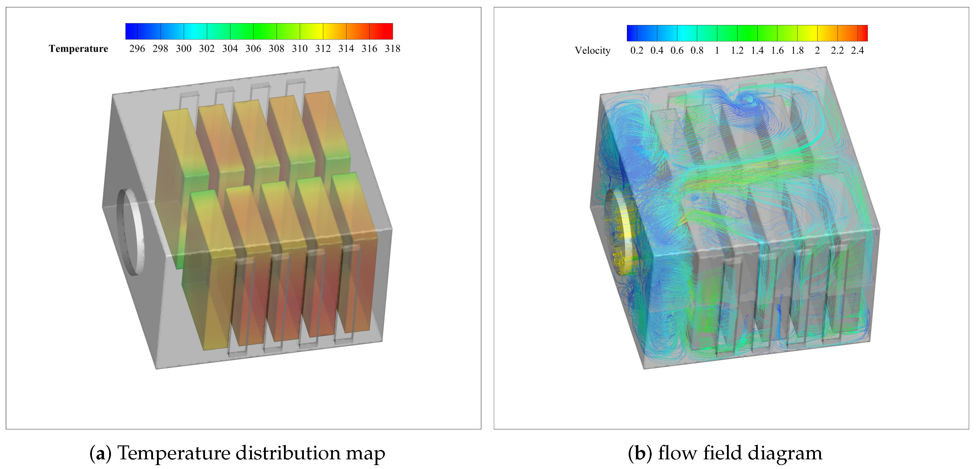
Based on actual operating conditions, the following settings were applied: A pressure-based solver was selected, using a transient solution method, with gravitational acceleration set to 9.81 m/s2 in the Y-axis direction. The S2S model in the radiation model was activated. The inlet was set as a velocity inlet with an airspeed of 2 m/s and an air temperature of 298.15 K. The outlet was set as a pressure outlet. The contact surfaces between the inner wall of the air and each battery, as well as the inner wall of the battery box and the air inside the box, was treated as a fluid–solid coupled heat transfer surfaces. The momentum, energy, and turbulence dissipation equations, and other control equations, were solved using the SIMPLEC algorithm and second-order upwind scheme. Simulation of 1 C, 1.5 C, and 2 C multiplier discharges were performed for individual battery storage packs. The simulation results are shown in Figure 2.
Figure 2a shows the temperature distribution cloud diagram, revealing an uneven cooling effect within the energy storage battery pack. The temperatures of batteries near the air inlet are generally lower than those near the air outlet. Figure 2b shows the flow diagram inside the battery pack, which shows that under the condition of fixed battery position, the cold air is mainly concentrated in the front side and the middle of the battery pack, and spreads from the middle to the two sides, and the air temperature rises gradually in the process. After analysis, it can be seen that due to the influence of flow resistance and thermal resistance, the airflow rate gradually decreases, resulting in a weakening of the cooling effect from the two sides to the center, making the temperature of the center area inside the battery pack low, resulting in a large temperature difference between the single cells. Therefore, there is significant room for improvement in the optimization of battery pack temperature. Figure 3 shows the simulation result data demonstrating the maximum temperature, minimum temperature, and temperature difference of ten individual cells. As the discharge multiplier increases, the three temperature data increase accordingly. When the discharge multiplication rate is 2 C, the temperature range of the cells in the battery pack is from 305.28 K to 317.30 K, and the maximum temperature difference reaches 12 K. However, the optimal operating temperature of lithium iron phosphate batteries is between 291.15 K and 318.15 K [28,29], and through a large number of experiments and practical applications, it has been measured that the acceptable range of temperature difference of single batteries should be no higher than 10 K. Thus, there is still room in this regard.

2.4. Experimental Results of the Original Model

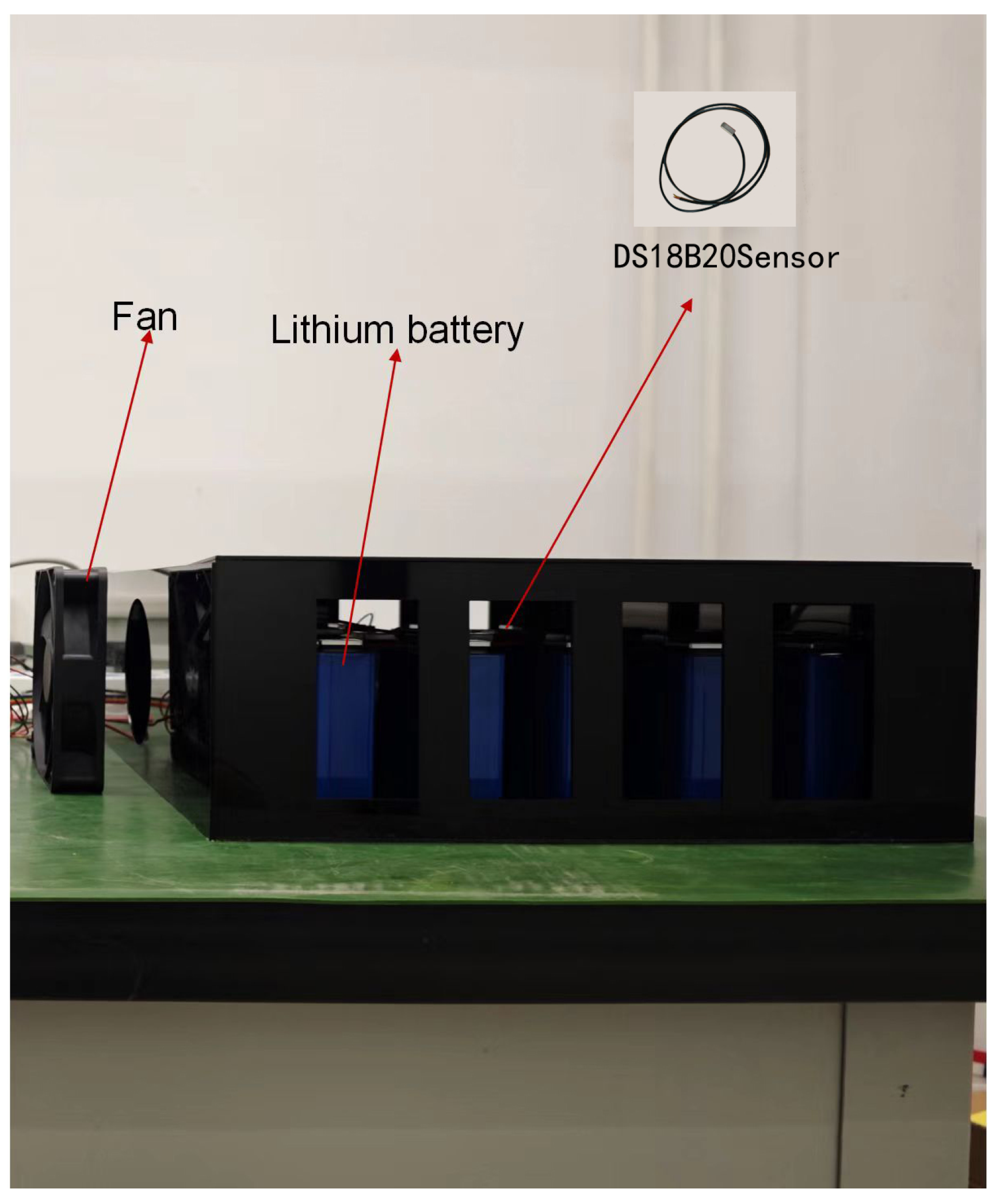
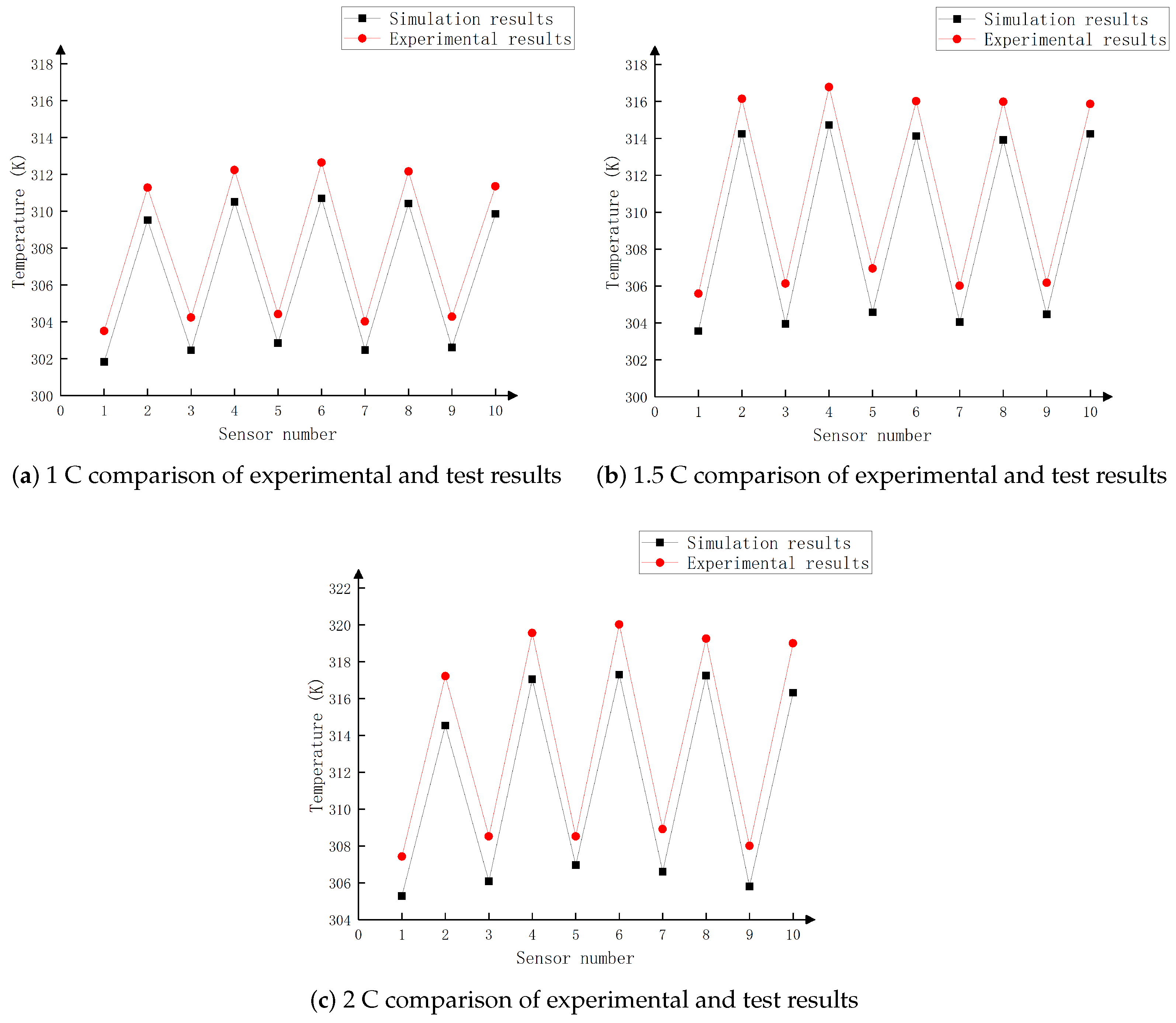
In order to verify the reasonableness of the battery pack air-cooled heat dissipation model and the validity of the simulation results, this study carried out temperature testing experiments on lithium-ion battery packs. The experimental platform is displayed in Figure 4. The experiment uses a temperature sensor model DS18B20 chip digital temperature sensor, the measurement range is 218.15 K to 398.15 K and the accuracy is ±0.5 K. As can be seen from Figure 5, the simulation and experimental results are generally consistent in the temperature trend, but there is an error. The error originates from the simulation model assuming that the heat source inside the battery pack is a constant value, while in the actual discharge process, the internal resistance of the battery increases with the discharge. Especially at the end of the discharge period, the rise of the internal resistance leads to an increase in the Joule heat and the heat of the side reaction inside the battery, which results in the experimental measurement point temperature being higher than the simulation value. After calculation, the maximum error is 2.72 K and the minimum error is 1.5 K for the three discharge multipliers. With the increase in the discharge multiplier, the error will increase somewhat. However, the overall range of error is still around 2 K, and the maximum is not more than 3 K. This proves the stability of the model.

3. Optimization of Air Cooling Heat Dissipation in Battery Packs

3.1. Analysis of Heat Transfer Performance of Batteries with Additional Heat Dissipation Ribs

The interior of the lithium-ion battery transfers heat to the casing through conduction. The formula for convective heat transfer is as follows,
q = h · A · ( T s u r f a c e T f l u i d )
where q is the heat transferred by convection, h is the convective heat transfer coefficient, A is the heat transfer surface area, T s u r f a c e is the surface temperature, and T f l u i d is the fluid temperature.
Assuming a fixed fluid temperature, enhancing battery heat transfer can be achieved by increasing the convective heat transfer coefficient and enlarging the heat transfer surface area, as indicated by the above formula. In this section, heat exchange is enhanced by installing heat dissipation ribs to increase the heat transfer surface area A .
As shown in Figure 6, the heat dissipation ribs are mounted on the high-temperature side of the monobloc cell, and this side is also near the air outlet. In engineering practice, the ideal thickness range of the base plate of heat dissipation ribs for electrical components is 4 to 10 mm. After comprehensive consideration, the base plate of the heat dissipation ribs is designed with a thickness of 4 mm, a length of 174 mm, and a width of 180 mm. Considering the distance from the inner wall of the battery pack casing, the fin height is set to 16 mm.
The convective heat transfer coefficient h is calculated as follows [30],
h L λ M = 0.664 R e M 1 2 P r M 1 3
where L is the characteristic length, λ M is the thermal conductivity of air, R e M is the Reynolds number, and P r M is the Prandtl number.
The Reynolds number, which indicates the flow state of the fluid, is calculated as follows,
R e M = ρ u L μ
where ρ is the air density, u is the average fluid velocity, and μ is the dynamic viscosity of the fluid.
The Prandtl number represents the ratio of fluid dynamic viscosity to thermal diffusivity and is calculated as follows,
P r M = c p μ λ M
where c p is the specific heat capacity of the fluid.
The total heat dissipation of the heat sink is calculated as follows [31],
Φ total = N λ B θ 0 m t h ( m H c ) + h A b Δ t
where N is the number of fins, H c is the corrected height, H c = H + Γ / 2 , A b is the base surface area, θ 0 is the excess temperature at the fin base and tip, Δ t is the thermal conductivity temperature difference, B is the cross-sectional area of the fin, and m is the fin combination parameter,
m = h p λ B 2 h λ Γ
where Γ is the fin thickness, p is the fin perimeter, and λ is the thermal conductivity of the fin.
The total heat dissipation efficiency of the heat sink is calculated as follows,
η = 1 N A f N A f + A b 1 t h ( m H c ) m H c
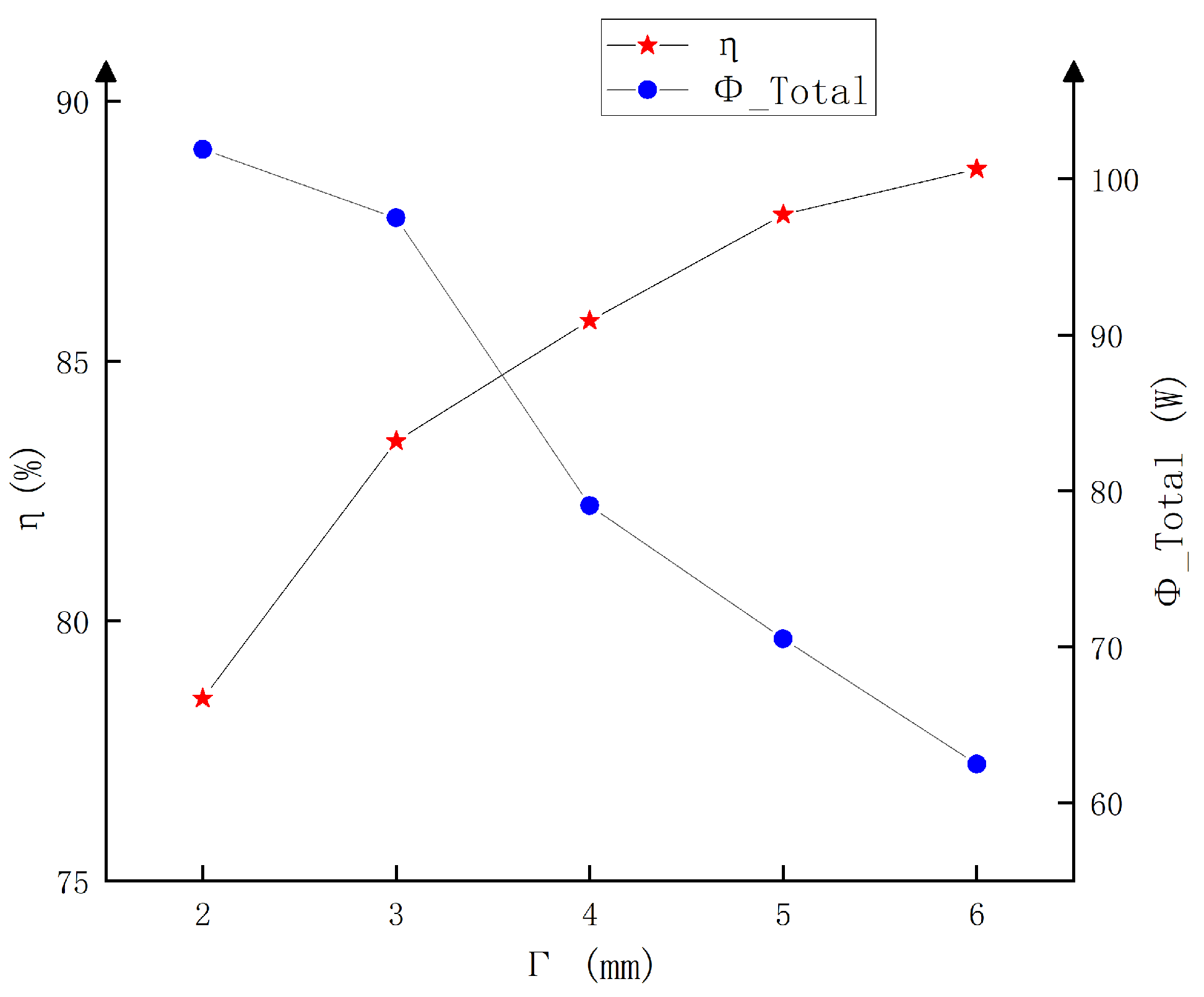
The convective heat transfer coefficient was calculated to be 14.60 W / ( m 2 · K ) . Figure 7 shows that, with the same rib height H , the total heat dissipation rate η increases with the rib thickness Γ , but the total heat dissipation Φ total always increases and decreases with the rib thickness Γ , so the value of the rib thickness cannot be too large. In order to ensure the hardness of the heat dissipation rib and ensure that it is easy to process, engineering generally sets the rib thickness to no less than 3 mm.
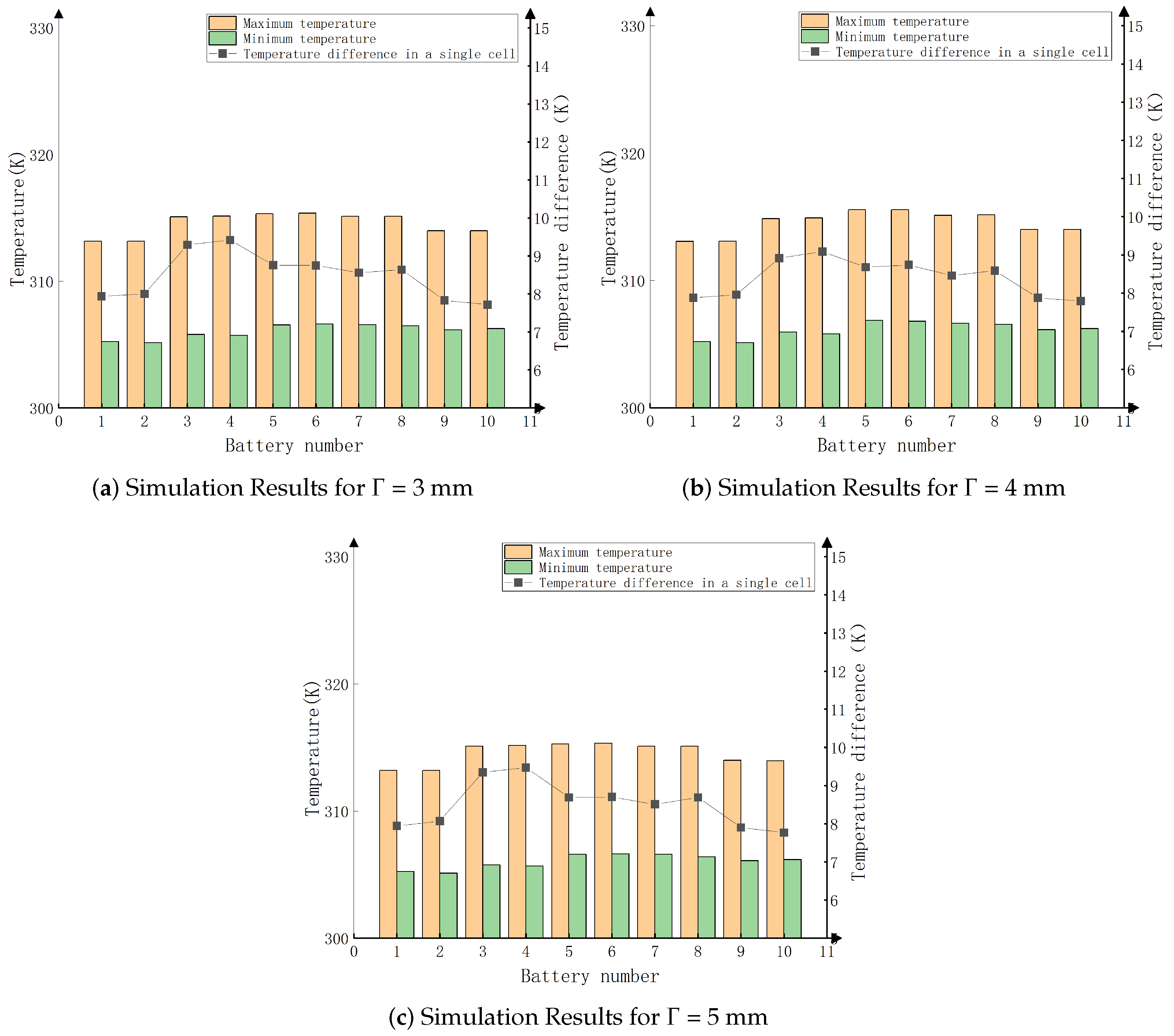
In this paper, the simulation calculates the cell temperature when the rib thickness is 3 mm, 4 mm, and 5 mm. The results are shown in Figure 8.
Combining the calculation results of total heat dissipation and total heat dissipation efficiency in Figure 7 and the simulation results under different rib thicknesses in Figure 8, the total heat dissipation rate efficiency reaches 86.2% when the thickness of the rib Γ = 4 mm. The cell uniformity is better, and the overall cell temperature ranges from 305.12 K to 315.32 K with a temperature difference of about 10 K.

3.2. Analysis of Heat Transfer Performance of Applied Thermal Coatings

In the forced convection cooling system, although convection heat transfer plays a leading role, radiation heat transfer should not be ignored. Radiant heat transfer can directly transfer heat energy between objects without direct contact with the material medium. Radiant heat transfer is calculated as follows,
Q radiation = ε σ A radiation ( T 1 4 T 0 4 )
where Q r a d i a t i o n is the radiative heat transfer, ε is the emissivity of the object’s surface (ranging from 0 to 1), σ is the Stefan–Boltzmann constant, A r a d i a t i o n is the surface area of the object, T 1 is the temperature of the object’s surface, and T 0 is the ambient temperature.
From the above formula, it is evident that increasing radiative heat transfer can be achieved by enhancing ε . Radiative cooling coatings incorporate fillers such as carbon nanotubes, spinel metal oxides, and nanoscale rare earth element oxides. These fillers create a macroscopically smooth and microscopically wavy radiative structure as the coating forms a film, significantly increasing the surface area and conductivity for heat dissipation and enhancing thermal exchange efficiency. Additionally, the spinel metal oxides, influenced by electron transitions, can elevate the electronic energy levels, thereby increasing the surface emissivity of the object. This study establishes an experimental measurement system centered around an infrared thermal imager to infer the surface emissivity of the object based on its temperature. The system measures the impact of coating thickness on infrared emissivity. The relationship between the temperature measured by the infrared thermal camera and the surface emissivity of the measured object is shown in the following equation [32],
T o b j s = { τ a t m [ ε T o b j T n + ( 1 α ) T u n ] + ε a t m T a t m n } 1 n
where T o b j s is the surface temperature of the object measured by the infrared thermal imager, τ a t m is the atmospheric transmittance, T o b j T is the true surface temperature of the object, α is the absorptivity of the object’s surface, T u is the ambient temperature, ε a t m is the atmospheric emissivity, and T a t m is the atmospheric temperature.
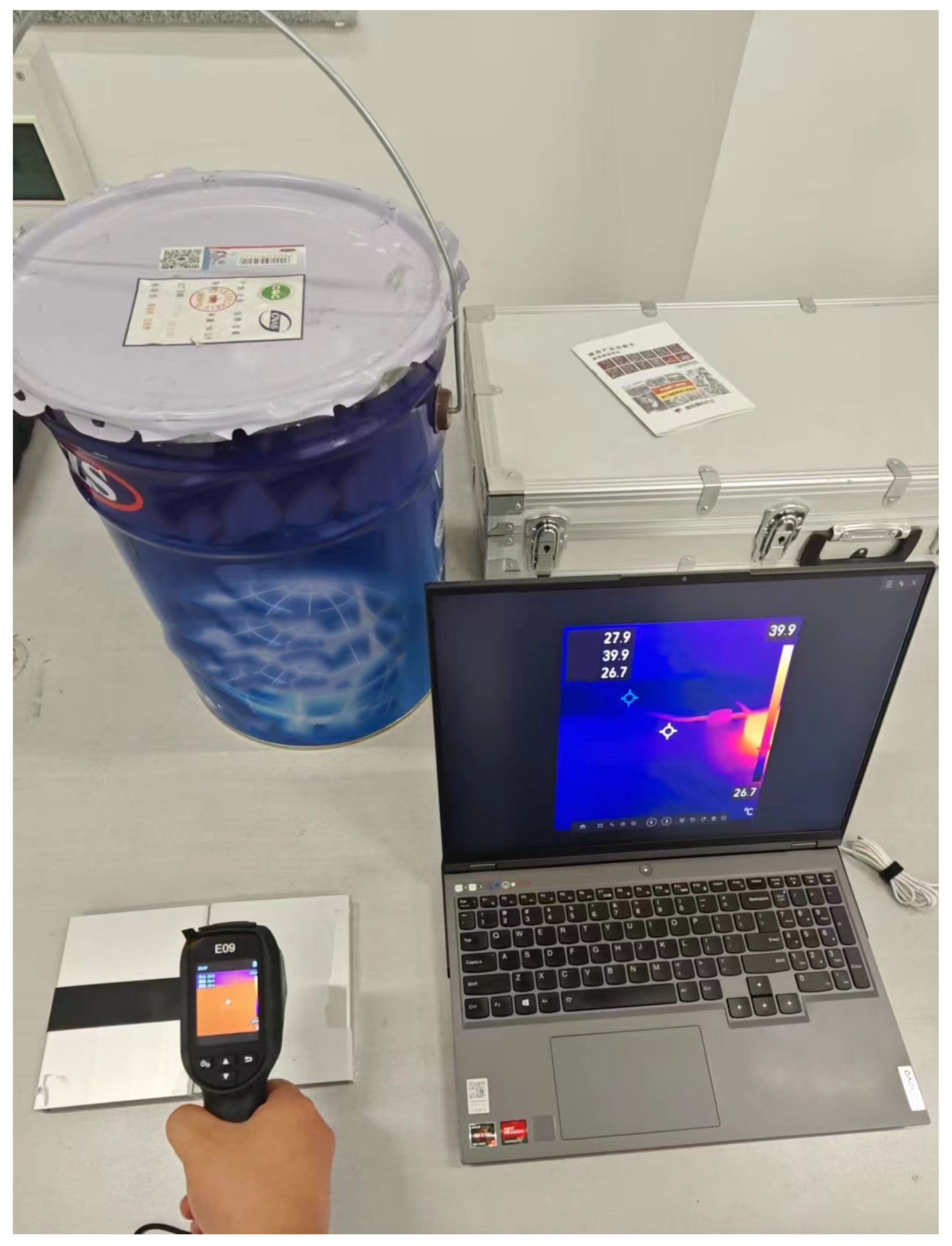
As shown in Equation (13), the temperature measured by the infrared thermal imager corresponds to the surface emissivity of the object. The emissivity of different thicknesses of coatings was measured and calibrated using an infrared imager by applying electrical insulating tapes with known emissivities on the test samples of the experimental platform shown in Figure 9. First, the test sample was placed on a temperature-controlled platform, and the preset emissivity of the infrared thermal imager was set to 0.95 to measure the temperature of the electrical insulation tape. Then, the infrared thermal imager was aimed at the surface of the coating, and the instrument’s emissivity was adjusted until the displayed temperature matched the measured temperature of the electrical insulation tape. The emissivity at this point corresponds to the emissivity of the coating at that thickness. The test results are shown in Figure 10.
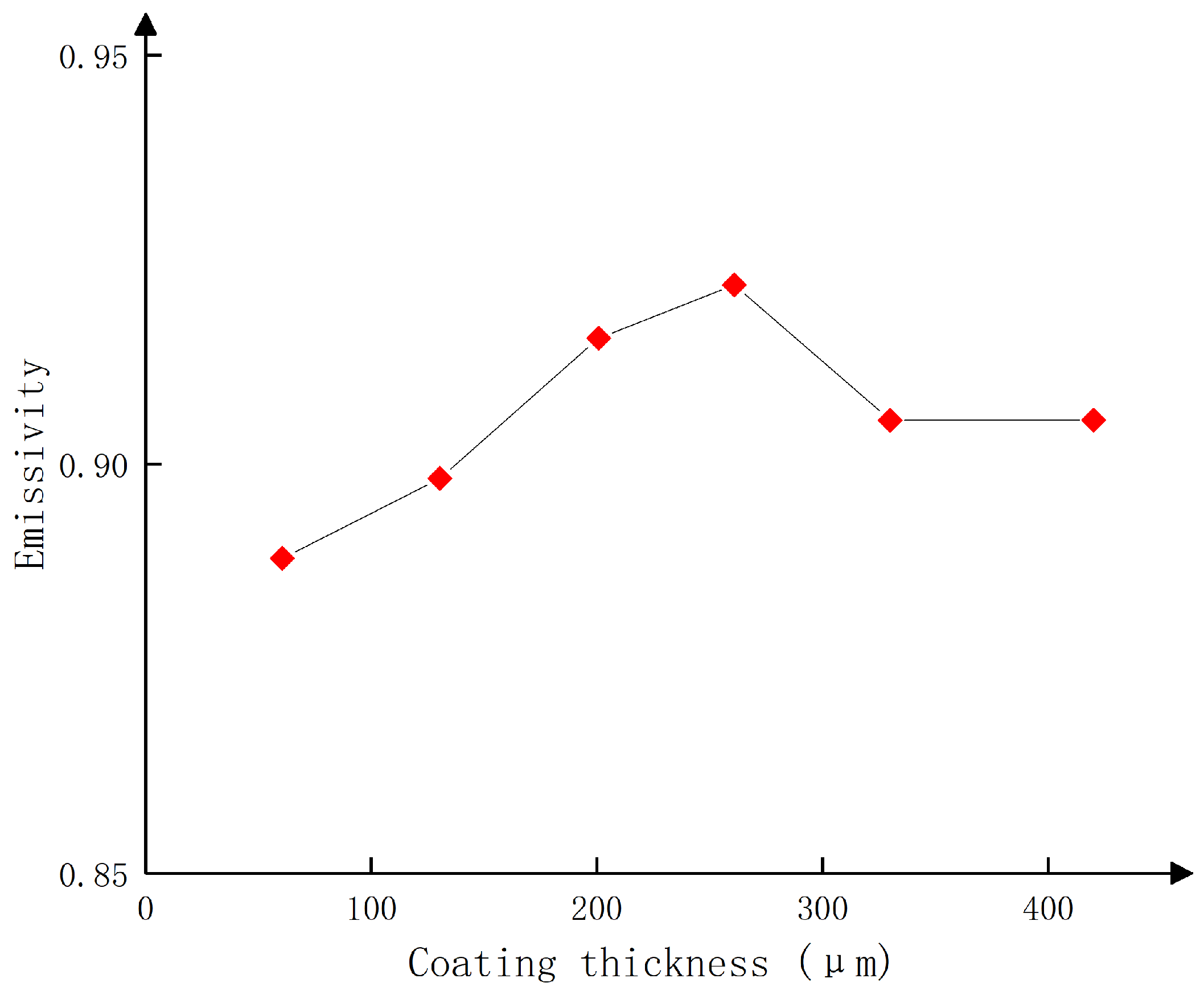
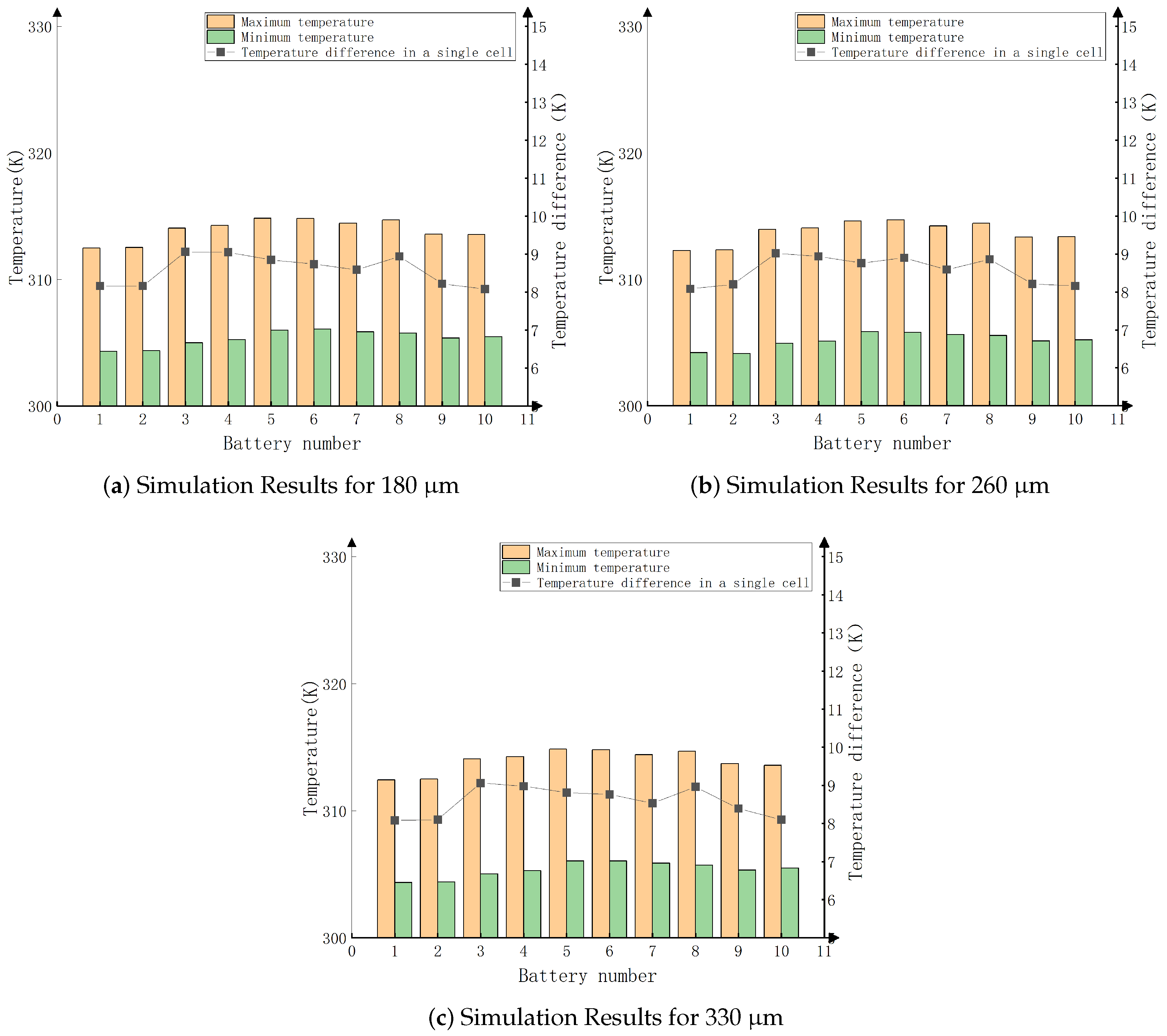
As shown in Figure 10, within the coating thickness range of 65–260 μ m, the emissivity increases with thickness. However, between 260–330 μ m, the emissivity decreases, and beyond 330 μ m, it remains relatively constant. Simulations were conducted with thicknesses of 180 μ m, 260 μ m, and 330 μ m (emissivities of 0.90, 0.92, and 0.90, respectively). The simulation results are shown in Figure 11.
As shown in Figure 11, the heat transfer efficiency on the surfaces of the battery and heat sink is better when using radiative cooling coatings compared to when no coating is used. This demonstrates that radiative cooling coatings can significantly enhance the radiative heat transfer performance within the battery pack. When the coating thickness is 260 μ m and the emissivity is 0.92, the temperature of each cell decreases by approximately 1.4 K as shown in Figure 3, and the temperature difference between individual cells is slightly reduced. With an emissivity of 0.90 and coating thicknesses of 180 μ m and 330 μ m, the temperature of each cell decreases by about 1.1 K, but the differences are not significant. Therefore, the optimal configuration is a coating thickness of 260 μ m and an emissivity of 0.92.

3.3. Analysis of Battery Heat Transfer Performance with Varying Fan Speeds

The convective heat transfer coefficient is a physical quantity that characterizes the efficiency of heat energy transfer between a fluid and a solid surface. The magnitude of this coefficient depends on various factors, including the physical properties of the fluid, the state of fluid flow, fluid velocity, and the characteristics of the solid surface. The formula is calculated as follows [33],
h 1 = 0.023 λ M L R e M 0.8 P r M 0.3
The relationship between wind speed and fan speed is as follows,
u = k × π × D × N 60
where k is an efficiency coefficient reflecting the aerodynamic efficiency of the fan (usually less than 1), D is the diameter of the fan blades, and N is the fan speed.
Equation (15) shows that wind speed is directly proportional to fan speed. Increasing the fan speed can increase the wind speed, thereby enhancing the convective heat transfer coefficient h 1 and improving the cooling effect. Therefore, simulations were conducted to analyze the temperature distribution at inlet wind speeds of 5 m/s, 8 m/s, and 11 m/s.
As shown in Figure 12, increasing the wind speed results in lower maximum and minimum temperatures, as well as reduced temperature differences, within the battery pack. This occurs because higher wind speeds enhance fluid flow, typically thinning the boundary layer. A thinner boundary layer shortens the heat transfer path, accelerating the transfer of heat from the solid surface to the fluid. This reduced boundary layer helps decrease the thermal resistance within the fluid, making it easier for heat to be carried away by convection. The larger temperature gradient enhances the heat flux, which is the amount of heat transferred per unit area per unit time.

4. Overall Optimization Experiment Analysis

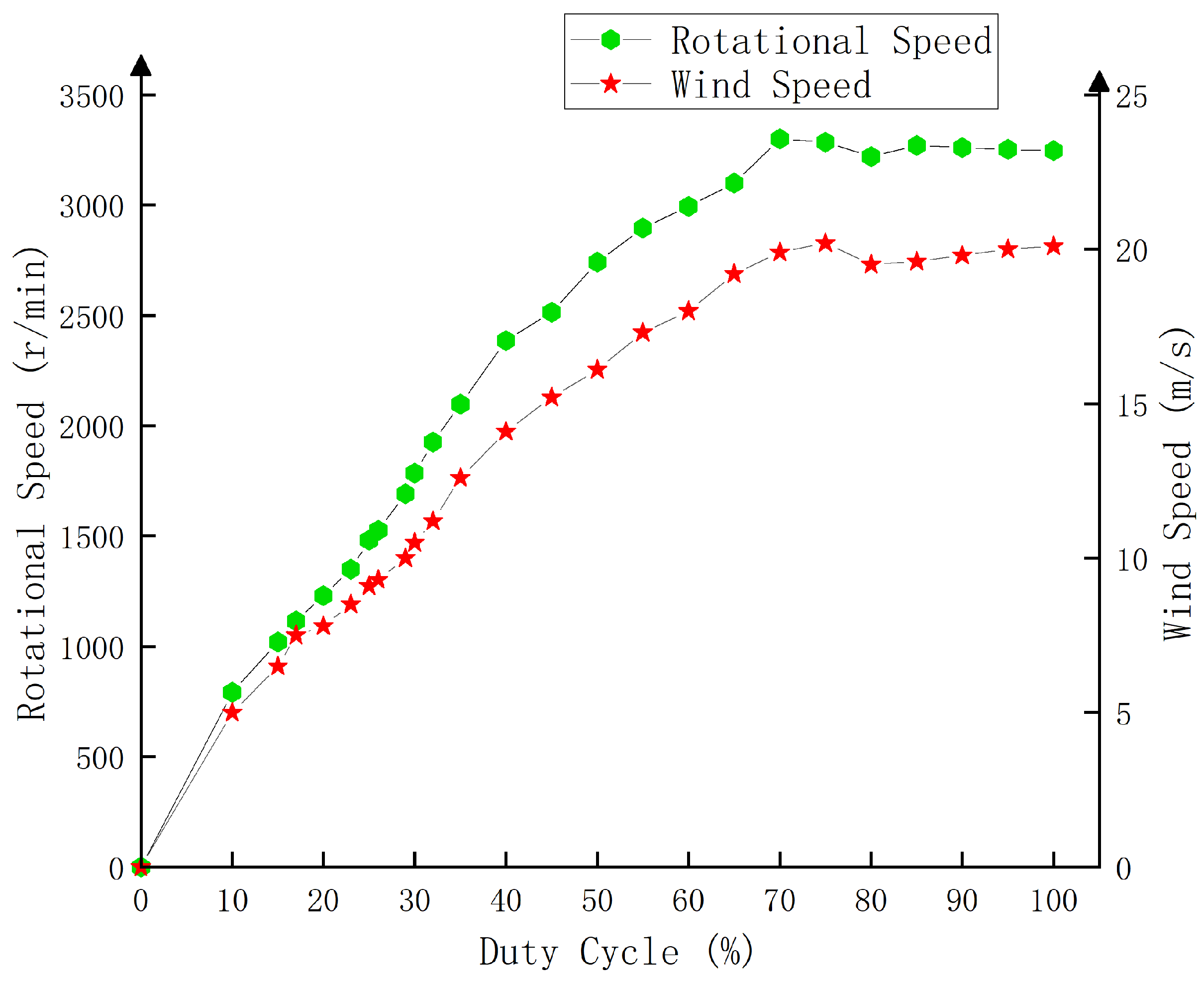
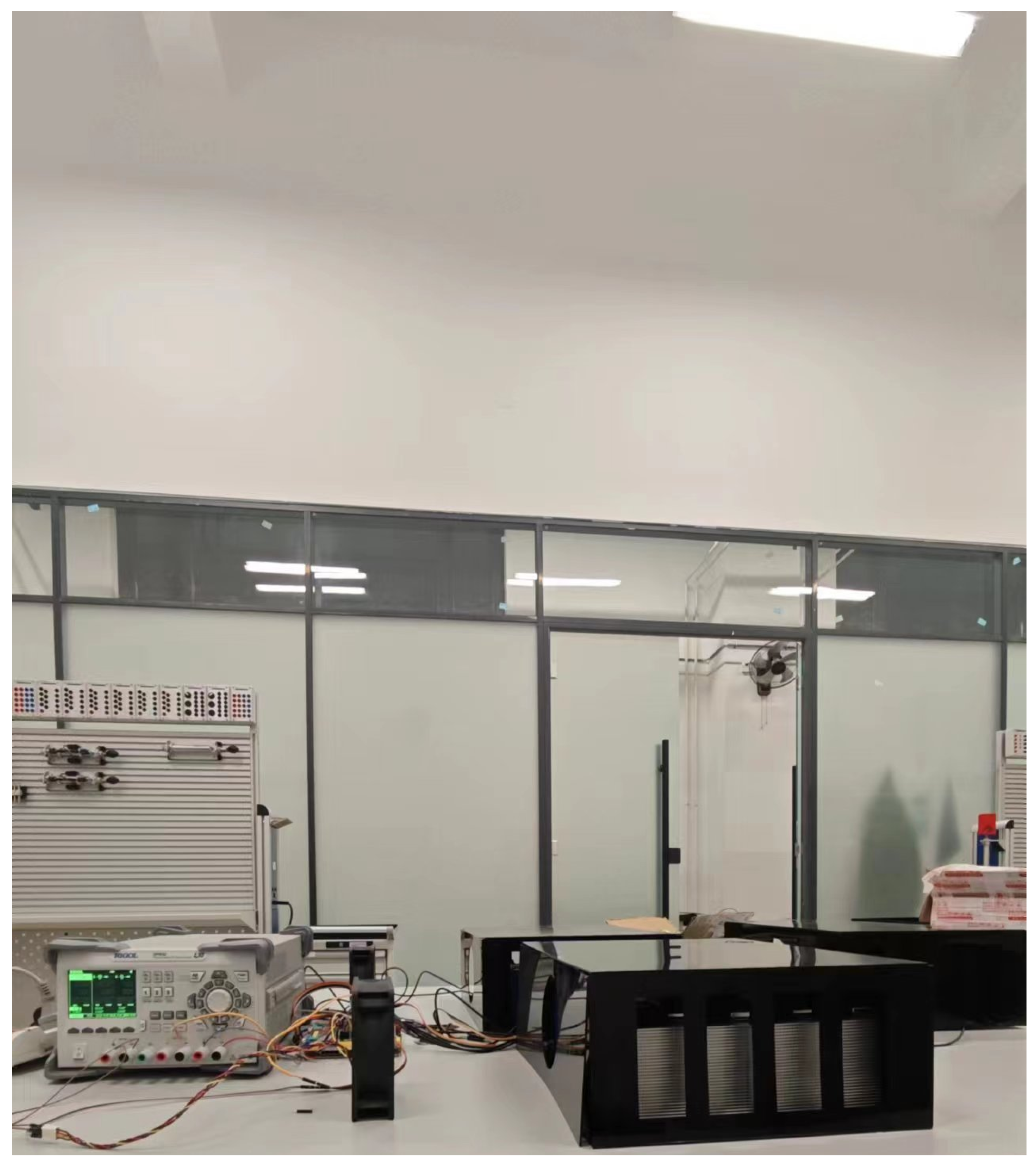
In this paper, a test platform as shown in Figure 13 is constructed using a power supply, a STM32 microcontroller, a five-hole probe tachometer, and a laser tachometer to measure the speed and air velocity characteristics of a cooling fan under different duty cycle conditions. The power supply provides electricity to the fan, and the STM32 microcontroller precisely controls the operating speed of the fan by adjusting the duty cycle of the PWM signal. A laser tachometer measures the rotational speed of the fan blades in a non-contact manner, and a five-hole probe tachometer is placed in front of the fan outlet to capture the wind speed data. During the experiment, the microcontroller gradually adjusts the duty cycle to change the fan speed. After each step of change, the corresponding rotational speed and wind speed data are recorded. Based on the data, the fan speed characteristic curve is plotted as shown in Figure 14.
Based on the results of the cooling fan characteristics test and experience, develop the battery temperature and fan speed control table shown in Table 2.
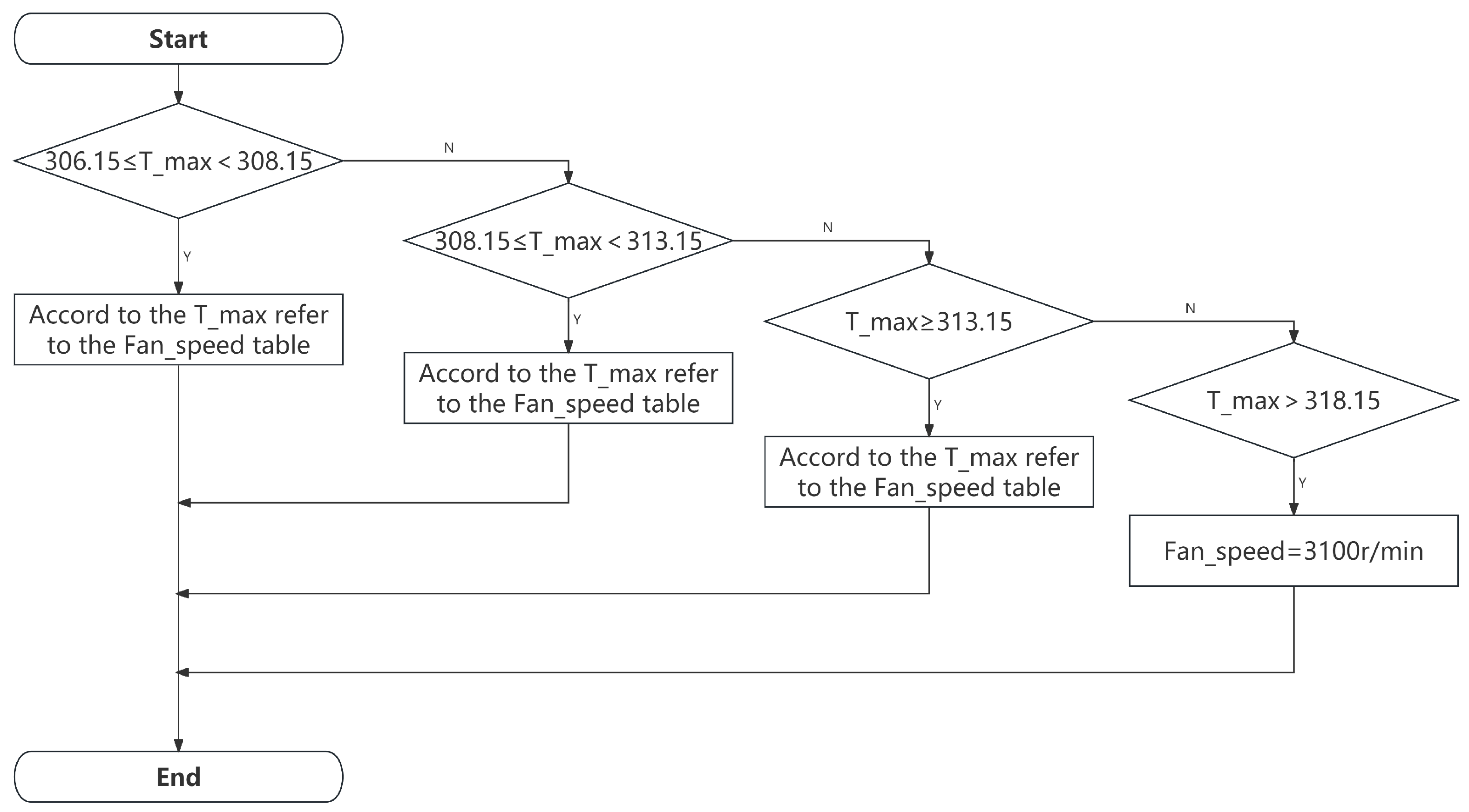
Based on the above optimization of heat dissipation, this paper proposes an innovative and efficient temperature management system based on the MIMO control strategy, which is specifically designed to precisely regulate the internal temperature of multiple Li-ion battery modules. The system integrates multiple temperature sensors as input units, which constantly monitor the real-time temperature of each Li-ion battery module to ensure real-time and accurate data. At the same time, the output unit of the system includes cooling fans inside each module, and the speed of these fans can be dynamically adjusted according to the specific instructions from the central processing unit to cope with various cooling needs. The heart of the system is the central processing unit, which receives and processes detailed data from all temperature sensors. By applying advanced control algorithms, the central processing unit analyzes this data, calculates the optimal speed required for each fan, and sends precise control signals accordingly. The control strategy used is shown in Figure 15.
Simulation of actual operation exists in which the temperature of the batteries in the remote module is generally higher relative to the battery module close to the outlet of the industrial air conditioner. If the temperature difference between different modules is too large, the overall performance of the energy storage system will be affected. Three experimental platforms for battery modules with different internal ambient temperatures as shown in Figure 16 were designed and constructed. Each battery module is equipped with a temperature sensor to monitor the internal temperature of the module in real time. The central processing unit is an STM32 microcontroller, which is responsible for receiving and processing data from all temperature sensors. Considering the need to avoid the risk of thermal runaway due to high battery temperature and the effect of fan switching frequency on fatigue life, the control strategy logic is set as follows: the fan turns on when the maximum battery temperature reaches 306.15 K. As can be seen from Figure 15, when the maximum battery temperature is greater than or equal to 306.15 K and less than 308.15 K, the fan speed is determined to be 792 r/min according to the way of checking Table 2. When the maximum battery temperature is greater than or equal to 308.15 K and less than 313.15 K, the fan speed is set to 1120 r/min. When the real-time maximum battery temperature is greater than or equal to 313.15 K and less than 318.15 K, check the table to determine the fan speed of 2741 r/min. When the fan speed reaches 3100 r/min (duty cycle of 67%), the speed has been relatively stable and will not continue to rise. Therefore, the maximum real-time temperature of the battery is greater than 318.15 K, which corresponds to a fan speed of 3100 r/min.
The experimental results are shown in Table 3, cases 1, 2, and 3 are the experimental results of the three battery packs A, B, and C at different ambient temperatures before optimization and with the highest constant speed, which proves that the maximum temperature, the minimum temperature, and the temperature difference of the three battery packs at different ambient temperatures decrease with the reduction in ambient temperatures, but the lowering of ambient temperatures implies the consumption of energy and the temperature difference between different modules is too large, which will affect the overall performance of the energy storage system, especially when a high current discharge is required, the output capacity of the whole storage system will be greatly affected. The temperature difference between different modules is too large, and the difference between the highest temperatures of different modules are as high as 7 K, which will affect the overall performance of the energy storage system, especially when high-current discharging is required, the output capacity of the whole energy storage system will be greatly reduced. At the same time, high fan speed for a long time will cause a series of impacts on the internal mechanical wear and tear of the fan. Conditions 4, 5, and 6 show the experimental results after the comprehensive improvement of the optimized heat dissipation measures and the addition of the control strategy to the fan speed control measures. The results prove that after optimization, the difference between the highest temperature of different modules is also reduced to significantly 3.33 K, which can solve the problem of the temperature difference between different modules is too large. At the same time, the battery temperature is controlled below 315.15 K, and the temperature difference is controlled within 5 K. It meets the working requirement conditions of a lithium battery.

5. Conclusions

This study delves into measures for enhancing the thermal management efficiency of lithium-ion batteries by optimizing the forced air cooling system.
  • Comprehensive Heat Transfer Model Establishment: This study has established, for the first time, a heat transfer model for lithium-ion battery packs that encompasses radiation, conduction, and convection. Through theoretical analysis and simulation calculations, this model provides a solid theoretical foundation for subsequent simulation experiments and practical applications. However, due to the assumptions made in the modeling of the heat source, there is an error between the simulation results and the experimental results. In order to reduce the error, the model can be considered to be optimized in two aspects: the internal resistance and the dynamic simulation of the heat source. By collecting experimental data under different conditions, an internal resistance model that changes dynamically with temperature and state of charge (SOC) is introduced. Meanwhile, the heat source should be a variable that changes with internal resistance and current; the battery model is calibrated and optimized using machine learning techniques. Machine learning methods are used to analyze large amounts of experimental data; discover complex nonlinear relationships between internal resistance, temperature, and SOC; and optimize heat source modeling. Predictive models are established to dynamically adjust the simulation parameters to make them closer to the experimental conditions.
  • Diversified optimization measures for cooling performance: The study improved the cooling performance of the system in all aspects by adding heat dissipation ribs, applying heat dissipation coatings and adjusting the fan speed. When the thickness of heat dissipation ribs is 4 mm, the total heat dissipation rate efficiency reaches 86.2%. Compared with the battery pack without any optimization, the maximum temperature is reduced by 1.98 K, and the maximum temperature difference is reduced by 1.94 K. When the thickness of heat dissipation coating is 260 μ m, the radiative rate is 0.92. Compared with the battery pack without any optimization, the maximum temperature is reduced by 1.4 K. The higher the fan rotation speed is, the better the heat dissipation effect is. The combined application of these optimization measures significantly reduces the operating temperature of the lithium battery, extends the cycle life of the battery, and improves the stability of the system.
  • Development of a temperature management system based on the MIMO control strategy: In this study, a temperature management system based on the MIMO control strategy is developed to achieve a dynamic balance of temperature and optimization of energy consumption. The application of this system not only improves the heat dissipation efficiency and ensures that the lithium-ion battery operates within the safe temperature limit of 318.15 K, thus extending the battery’s cycle life and enhancing its stability, but also significantly reduces the risk of thermal runaway. The problem of excessive temperature difference between different battery modules is solved and the output capacity of the system is improved.

Author Contributions

Conceptualization, Q.W.; methodology, Q.W. and L.Y. (Linbin Yan); software, L.Y. (Lushi Yang); validation, L.Y. (Linbin Yan); resources, J.W.; data curation, L.Y. (Linbin Yan); writing—original draft preparation, L.Y. (Linbin Yan); writing—review and editing, Q.W. and L.Y. (Linbin Yan); supervision, Q.W. All authors have read and agreed to the published version of the manuscript.

Funding

This research was funded by the National Natural Science Foundation of China, grant number U1966204.

Data Availability Statement

Data are contained within the article.

Conflicts of Interest

The authors declare no conflicts of interest.

References

  1. Kumar, R.; Goel, V. A study on thermal management system of lithium-ion batteries for electrical vehicles: A critical review. J. Energy Storage 2023, 71, 108025. [Google Scholar] [CrossRef]
  2. Zhou, S.; Song, Z.; Zhao, Y. Analysis of the thermal effect of a lithium iron phosphate battery cell and module. Energy Sci. Eng. 2021, 9, 661–675. [Google Scholar] [CrossRef]
  3. Akbarzadeh, M.; Kalogiannis, T.; Jaguemont, J.; Jin, L.; Behi, H.; Karimi, D.; Beheshti, H.; Mierlo, J.V.; Berecibar, M. A comparative study between air cooling and liquid cooling thermal management systems for a high-energy lithium-ion battery module. Appl. Therm. Eng. 2021, 198, 117503. [Google Scholar] [CrossRef]
  4. Tuğan, V.; Yardımcı, U. Numerical study for battery thermal management system improvement with air channel in electric vehicles. J. Energy Storage 2023, 72, 108515. [Google Scholar] [CrossRef]
  5. Xu, Z.; Yu, G.; Zhang, T.; Wang, R. Cooling performance of battery pack as affected by inlet position and inlet air velocity in electric vehicle. Case Stud. Therm. Eng. 2022, 39, 102382. [Google Scholar] [CrossRef]
  6. Yang, W.; Wang, Y.; Guo, F.; Bai, Y.; Liu, X. Optimization study of air-cooled stagger-arranged battery pack with reverse-layered airflow. J. Energy Storage 2022, 55, 105524. [Google Scholar] [CrossRef]
  7. Li, H.; Xiao, X.; Wang, Y.; Lian, C.; Li, Q.; Wang, Z. Performance investigation of a battery thermal management system with microencapsulated phase change material suspension. Appl. Therm. Eng. 2020, 180, 115795. [Google Scholar] [CrossRef]
  8. Basu, S.; Hariharan, K.S.; Kolake, S.M.; Song, T.; Sohn, D.K.; Yeo, T. Coupled electrochemical thermal modelling of a novel Li-ion battery pack thermal management system. Appl. Energy 2016, 181, 1–13. [Google Scholar] [CrossRef]
  9. Deng, T.; Zhang, G.; Ran, Y. Study on thermal management of rectangular Li-ion battery with serpentine-channel cold plate. Int. J. Heat Mass Transf. 2018, 125, 143–152. [Google Scholar] [CrossRef]
  10. E, J.; Han, D.; Qiu, A.; Zhu, H.; Deng, Y.; Chen, J.; Zhao, X.; Zuo, W.; Wang, H.; Chen, J.; et al. Orthogonal experimental design of liquid-cooling structure on the cooling effect of a liquid-cooled battery thermal management system. Appl. Therm. Eng. 2018, 132, 508–520. [Google Scholar]
  11. Wu, C.; Wang, Z.; Bao, Y.; Zhao, J.; Rao, Z. Investigation on the performance enhancement of baffled cold plate based battery thermal management system. J. Energy Storage 2021, 41, 102882. [Google Scholar] [CrossRef]
  12. He, P.; Lu, H.; Fan, Y.; Ruan, H.; Wang, C.; Zhu, Y. Numerical investigation on a lithium-ion battery thermal management system utilizing a double-layered I-shaped channel liquid cooling plate exchanger. Int. J. Therm. Sci. 2023, 187, 108200. [Google Scholar] [CrossRef]
  13. Zhao, D.; An, C.; Lei, Z. Liquid cooling plate with drop-shaped deflectors based on Coanda Effect-For Li-ion battery thermal management. J. Energy Storage 2023, 70, 108014. [Google Scholar] [CrossRef]
  14. Yang, H.; Wang, Z.; Li, M.; Ren, F.; Feng, Y. A manifold channel liquid cooling system with low-cost and high temperature uniformity for lithium-ion battery pack thermal management. Therm. Sci. Eng. Prog. 2023, 41, 101857. [Google Scholar] [CrossRef]
  15. Zeng, W.; Ma, C.; Hu, S.; Li, S.; Zhang, Y. The performance investigation and optimization of reciprocating flow applied for liquid-cooling-based battery thermal management system. Energy Convers. Manag. 2023, 292, 117378. [Google Scholar] [CrossRef]
  16. Xu, S.; Su, Y.; Wang, W. Numerical Simulation Study on the Thermal Characteristics of Lithium-ion Battery Packs in Electric Vehicles. Sci. Technol. Eng. 2018, 18, 55–61. [Google Scholar]
  17. Liu, X.; Zou, T.; Hou, H.; Xu, Z.; Wang, X. Numerical Study on the Air-cooled Temperature Field of Lithium-ion Batteries and Modules Based on Fluent. Softw. Guide 2020, 19, 5–10. [Google Scholar]
  18. Li, M.; Zang, M.; Li, C.; Dai, H. Optimization of the Air-cooled Heat Dissipation Structure of Lithium-ion Battery Packs. Battery 2020, 50, 266–270. [Google Scholar]
  19. Yang, K.; Pei, H.; Zhu, X.; Zou, Y.; Wang, J.; Shi, H. Thermal Design Research and Optimization of a Specific Type of Containerized Energy Storage Battery Module. Energy Storage Sci. Technol. 2020, 9, 1858. [Google Scholar]
  20. Huang, X.; Dai, H.; Hu, L.; Zhu, J.; Huang, X.; Yang, Z.; Li, C. Thermal Simulation of Power Battery Packs Based on COMSOL Multiphysics. Automot. Appl. Technol. 2022, 47, 1–9. [Google Scholar]
  21. Mahamud, R.; Park, C. Reciprocating air flow for Li-ion battery thermal management to improve temperature uniformity. J. Power Sources 2011, 196, 5685–5696. [Google Scholar] [CrossRef]
  22. Fan, L.; Khodadadi, J.M.; Pesaran, A.A. A parametric study on thermal management of an air-cooled lithium-ion battery module for plug-in hybrid electric vehicles. J. Power Sources 2013, 238, 301–312. [Google Scholar] [CrossRef]
  23. Park, H. A design of air flow configuration for cooling lithium ion battery in hybrid electric vehicles. J. Power Sources 2013, 239, 30–36. [Google Scholar] [CrossRef]
  24. Yang, T.; Yang, N.; Zhang, X.; Li, G. Investigation of the thermal performance of axial-flow air cooling for the lithium-ion battery pack. Int. J. Therm. Sci. 2016, 108, 132–144. [Google Scholar] [CrossRef]
  25. Lv, C.; Zhang, S.; Zhu, S.; Song, Y.; Ge, Y. Thermal simulation analysis and optimization of forced air cooling system for energy storage lithium-ion battery pack. Power Syst. Prot. Control 2021, 49, 48–55. [Google Scholar]
  26. Liu, Z.; Wang, Y.; Zhang, J.; Liu, Z. Shortcut computation for the thermal management of a large air-cooled battery pack. Appl. Therm. Eng. 2014, 66, 445–452. [Google Scholar] [CrossRef]
  27. Chen, S.C.; Wan, C.C.; Wang, Y.Y. Thermal analysis of lithium-ion batteries. J. Power Sources 2005, 140, 111–124. [Google Scholar] [CrossRef]
  28. Mevawalla, A.; Shabeer, Y.; Tran, M.K.; Panchal, S.; Fowler, M.; Fraser, R. Thermal modelling utilizing multiple experimentally measurable parameters. Batteries 2022, 8, 147. [Google Scholar] [CrossRef]
  29. Xie, Y.; Li, W.; Hu, X.; Tran, M.-K.; Panchal, S.; Fowler, M.; Liu, K. Coestimation of SOC and three-dimensional SOT for lithium-ion batteries based on distributed spatial–temporal online correction. IEEE Trans. Ind. Electron. 2022, 70, 5937–5948. [Google Scholar] [CrossRef]
  30. Geng, D.; Hu, Y. Structural design of CPU cooler. J. Shenyang Univ. Technol. 2011, 30, 82–85. [Google Scholar]
  31. Lee, J.; Rew, K.; Lee, C.; Kim, D.; Kim, M. A study on heatsink fin wave optimization for climate control seat. J. Mech. Sci. Technol. 2017, 31, 1489–1495. [Google Scholar] [CrossRef]
  32. Yin, H.; Yin, Z. Numerical calculation of the effect of thermal conductivity of anticorrosive coatings on the heat dissipation capacity of chip radiators. Sci. Technol. Eng. 2020, 20, 5142–5148. [Google Scholar]
  33. Serrano, D.; Sánchez-Delgado, S.; Pérez-Álvarez, R.; Acosta-Iborra, A. Experimental determination of the convection heat transfer coefficient in an eccentric annular duct. Exp. Therm. Fluid Sci. 2022, 136, 110664. [Google Scholar] [CrossRef]
Figure 1. Energy storage container and battery pack structure.
Energies 17 03504 g001
Figure 2. Temperature distribution and flow field simulation results.
Energies 17 03504 g002
Figure 3. Data plots of simulation results with different magnification.
Energies 17 03504 g003
Figure 4. Battery pack physical picture.
Energies 17 03504 g004
Figure 5. Battery pack physical and test result diagrams.
Energies 17 03504 g005
Figure 6. Three-dimensional model for adding a heat sink.
Energies 17 03504 g006
Figure 7. Total heat dissipation and total thermal efficiency of the radiator.
Energies 17 03504 g007
Figure 8. Simulation results with different thicknesses of heat sinks.
Energies 17 03504 g008
Figure 9. Emissivity measurement platform.
Energies 17 03504 g009
Figure 10. Relationship between emissivity and coating thickness.
Energies 17 03504 g010
Figure 11. Simulation results for different thicknesses of cooling coatings.
Energies 17 03504 g011
Figure 12. Simulation results at different wind speeds.
Energies 17 03504 g012
Figure 13. Fan performance test platform.
Energies 17 03504 g013
Figure 14. The characteristic curve of the cooling fan’s rotational speed.
Energies 17 03504 g014
Figure 15. The control strategy flowchart.
Energies 17 03504 g015
Figure 16. Photograph of the system.
Energies 17 03504 g016
Table 1. Lithium iron phosphate battery parameters.
ParameterNumerical Value
Length × Width × Height (mm)135 × 30 × 180
Nominal capacity (Ah)50
Nominal voltage (V)3.2
End-of-charge voltage (V)3.65
Cutoff voltage during discharge (V)2.5
Maximum charge and discharge C-rate (C)2
Operating temperature under charging conditions (K)273.15∼318.15
Operating temperature under discharge conditions (K)253.15∼328.15
Table 2. Comparison table of battery temperature and fan speed.
Temperature/(K)Fan Speed (r/min)Duty Cycle (%)
306.1579210
308.15112017
313.15274150
318.15310067
Table 3. Comparison of experimental results before and after optimization.
Operating ConditionAmbient Temperature/(K)Battery PackFan Speed (r/min)Maximum Temperature/(K)Minimum Temperature/(K)Temperature Difference/(K)
1293.15A3100305.61298.127.49
2296.15B3100309.55300.998.56
3298.15C3100312.87302.2310.64
4293.15A310.64306.663.98
5296.15B312.17308.024.15
6298.15C313.97309.234.74
※ Represents the variation of fan speed with temperature.
Disclaimer/Publisher’s Note: The statements, opinions and data contained in all publications are solely those of the individual author(s) and contributor(s) and not of MDPI and/or the editor(s). MDPI and/or the editor(s) disclaim responsibility for any injury to people or property resulting from any ideas, methods, instructions or products referred to in the content.