Article

Evaluating the Impact of CO2 Capture on the Operation of Combined Cycles with Different Configurations

Department of Engineering and Applied Sciences, University of Bergamo, Viale Marconi 5, 24044 Dalmine, Italy
*
Author to whom correspondence should be addressed.
Energies 2024, 17(14), 3501; https://doi.org/10.3390/en17143501
Submission received: 15 June 2024 / Revised: 10 July 2024 / Accepted: 12 July 2024 / Published: 17 July 2024
(This article belongs to the Topic Evolution of Land-Based Gas Turbines)

Highlights

What are the main findings?
  • Given the role played by natural gas combined cycles (NGCCs) in balancing the grid and offsetting renewable energy fluctuations, the application of post-combustion carbon capture through an amine-based process was evaluated from a thermodynamic point of view, taking into account realistic power plant configurations.
  • The study explores part-load behavior with a focus on gas turbine control strategy: inlet air flow, fuel flow rate, and exhaust temperature determine not only the efficiency of the topping and bottoming cycle but also the energy requirements for CO2 capture and thus the overall performance.
What is the implication of the main finding?
  • This study suggests that applying an appropriate part-load strategy can help reduce the burden of retrofitting the capture process to existing NGCCs within the constraints of the specific gas turbine model.
  • Regarding new “decarbonized” NGCCs, design guidelines could enable less complex and therefore less costly configurations by considering the capture unit as an integral part of the system from the beginning of the project.

Abstract

:
In order to reduce greenhouse gas emissions associated with power generation, the replacement of fossil fuels with renewables must be accompanied by the availability of dispatchable sources needed to balance electricity demand and production. Combined cycle (CC) power plants adopting post-combustion capture (PCC) can serve this purpose, ensuring near-zero CO2 emissions at the stack, as well as high efficiency and load flexibility. In particular, the chemical absorption process is the most established approach for industrial-scale applications, although widespread implementation is lacking. In this study, different natural gas combined cycle (NGCC) configurations were modeled to estimate the burden of retrofitting the capture process to existing power plants on thermodynamic performance. Simulations under steady-state conditions covered the widest possible load range, depending on the gas turbine (GT) model. Attention was paid to the net power loss and net efficiency penalty attributable to PCC. The former can be mitigated by lowering the GT air–fuel ratio to increase the CO2 concentration (XCO2) in the exhaust, thus decreasing the regeneration energy. The latter is reduced when the topping cycle is more efficient than the bottoming cycle for a given GT load. This is likely to be the case in the less-complex heat recovery units.

1. Introduction

The amount of warming the Earth is experiencing is the result of more than a century of gas emissions from human activities. The likely range of total human-caused global surface temperature increase from 1850–1900 to 2010–2019 is 0.8 °C to 1.3 °C. Rising temperatures have led to rapid and widespread changes in the atmosphere, oceans, cryosphere, and biosphere. Examples include sea level rise, global retreat of glaciers, spatial variations in precipitation, and increase in the frequency and intensity of extreme weather events [1]. The cascading impacts of climate change on food security and nutrition are already affecting the most vulnerable [2].
CO2 emissions are the main driver of global warming: after a drop in 2020 due to the effects of the COVID-19 pandemic, the upward trajectory of global CO2 emissions resumed. In 2022, total energy-related CO2 emissions (including those from energy generation as well as energy-related industrial processes) reached 36.8 Gt [3]. An additional 1.1 percent growth occurred in 2023, thus reaching a new record high of 37.4 Gt. This was mainly due to the economic rebound and a further increase in fossil fuel consumption: unabated coal was chosen as a cheaper but more emissive fuel, compared with natural gas (NG), especially in emerging economies [4]. Despite the good news of slower CO2 emissions growth than global economic activity in 2023 (~3%), the rapid downward trend needed to meet the global climate goals set in the Paris Agreement is far from being achieved. This means that the annual increase in global capacity and use of clean energy, while reaching, in 2023, the fastest growth rate in two decades, is still not enough to achieve the decarbonization targets defined by COP28 [5]. Furthermore, a net zero emissions scenario cannot rely only on renewables, such as solar and wind power. These need to be complemented by progress across grid infrastructure, storage, and dispatchable low-emission generation, with the aim of ensuring flexible and secure operation of electricity systems. Fossil fuels with carbon capture will remain important through the next decades as providers of seasonable flexibility and benefits essential to the operation of electricity grids, such as inertia and frequency control [6]. They can contribute to meeting the additional demand of global electricity as a result of population and income growth and the electrification of increasing numbers of end-uses, especially in emerging markets and developing economies [7].
For the first time in a decade, several carbon capture and storage (CCS) projects are under construction around the world. As of 31 July 2023, total CO2 capture capacity increased by nearly 50% compared to 2022 and the outlook is for continued growth. North America is the world leader in CCS deployment due to substantial policy enhancements, particularly the US Inflation Reduction Act [8]. It should be noted that investment in CCS is mainly driven by government policy and regulation, which may include emission trading systems, carbon taxes, and any direct or indirect subsidies (such as tax credits, loan provision, grants, or loan guarantees). Since costs of CO2 capture typically decrease with increased XCO2 in the flue gas, application to power generation, with CO2 quite diluted, is the most challenging [9]. In fact, flue gases exit the stack close to atmospheric pressure, with a XCO2 of 7 to 14% in coal-fired power plants, whereas in the case of gas-fired power plants, it drops to a value of about 4%. This is a serious challenge that helps explain why few CCS projects are in the operational phase, given the large size and high capital costs of the process apparatus [10].
When it comes to retrofitting existing power plants, post-combustion technologies are the most frequently considered. Among them, chemical absorption is the most mature and reliable CO2 separation technique [11]. The typical 30 wt% mono-ethanolamine (MEA) solution has well-characterized performance: it allows CO2 capture rates above 95% and a CO2 product purity of 99.9 vol% (dry). Indeed, it is considered the industry standard, with the MEA concentration resulting from the trade-off between capture performance and MEA degradation and corrosion. Also, CO2 purity meets product specifications in most cases, so an additional purification step may not be necessary [12]. On the one hand, MEA is the most widely used due to its low viscosity and volatility, high selectivity, rapid reaction, and relatively low cost. On the other hand, it is also sensitive to impurities and requires flue gas desulfurization and denitrification to work effectively. Most importantly, the regeneration process is highly energy intensive, which is an economic and environmental barrier to the widespread adoption of this technology [13]. Moreover, the toxic degradation products generated need additional handling [14]. Second-generation solvents are maturing with the goal of weakening CO2-amine bonds, thereby decreasing the energy associated with CO2 release without a significant reduction of the CO2 absorption rate [15]. But today, conventional liquid amine systems are the go-to method for capturing CO2, especially at low partial pressures. Their application to NGCCs may result in increased operational costs, reduced power output [16], and a net efficiency penalty between 7 and 9 percentage points (pp)—for a CO2 capture rate of 90%—but has significant potential to diminish greenhouse gas emissions in the power sector [17].
Moving from theory to practice, despite the rapid escalation in the development of new CCS projects, relatively few have yet reached the engineering design stage. We can mention those reported by the National Energy Technology Laboratory [18], with a CO2 capture rate of at least 95%, adopting a solvent-based process:
  • Cane Run 7, Kentucky’s first NGCC, with a capacity of 640 MW;
  • General Electric Gas Power domestic NGCC located in Schenectady, NY, USA;
  • Calpine’s Delta Energy Center, a 944 MW NGCC located in Pittsburg, CA, USA;
  • PK2, an 1190 MW NGCC belonging to the Polk Power Station located in Mulberry, FL, USA.
Additional projects have been selected for award negotiations within the “Carbon Capture Demonstration Projects” program administered by DOE [19]:
  • Baytown Energy Center (Baytown, TX, USA), a 896 MW NGCC operated in combined-heat and power mode;
  • A 1.2 GW NGCC power plant located in Deer Park, TX, USA;
  • Sutter Energy Center, a 550 MW NGCC near Yuba City, CA, USA.
RWE, the UK’s leading electricity generator, is testing the feasibility of options to retrofit PCC technology at its NGCC power stations at Pembroke and Stay Thorpe. It is also developing proposals for a new carbon-capture, gas-fired power station at Stallingborough with a capacity of 800 MW.
All these projects share a focus on operability, including startup, shutdown, and a range of power outputs, which are critical to enable NGCC plants with CCS in load-following mode to facilitate the integration of intermittent renewable sources. Available experimental data related to these conditions are currently very limited but encouraging: flexible operation of the amine PCC is possible provided that careful monitoring of the parameters governing the CO2 absorption/desorption process is carried out [20,21].
At least, there is a greater availability of scientific publications related to thermodynamic modeling of NGCC coupled with PCC, both at design and off-design conditions. The general conclusion is that the NGCC is always capable of supplying the capture unit with sufficient steam for solvent regeneration at full load, part load, and during load changes [22]. However, even if the pressure requirement of the steam to be extracted can be met at part load, the minimum turndown should still ensure a difference greater than zero between the steam pressure at the point of the extraction from the turbine and that required in the reboiler. The same applies to steam temperature. For this reason, the minimum GT load varies according to the case study: 60% in [23], 35% in [24], and 50% in [25].
As GT load is reduced, the amount of CO2 captured decreases: the optimal liquid-to-gas ratio in the absorber, which minimizes the specific reboiler duty (SRD), should be lowered to maintain the desired level of CO2 removal efficiency [26,27]. However, there is no agreement on the corresponding regeneration energy trend: SRD decreases at part load in [26], while the opposite occurs in [27]. Even considering dynamic modeling, it seems that the addition of PCC to a NGCC should not impose any constraints on operation under scheduled load changes. The stabilization times of the main power island parameters were found to be significantly shorter (up to half an hour) than those of the PCC unit (up to 4 h) [28]. Despite different transient time scales, disturbances in steam extraction to feed the PCC unit have negligible impact on the power generation dynamics of the NGCC system [29].
In light of this, the thermodynamic modelling reported here is steady state, with energy and mass balances solved iteratively until convergence is achieved. The works cited [22,23,24,25,26,27,28,29] all refer to NGCC models with a triple-pressure heat recovery steam generator (HRSG), to represent the most efficient technology. The novelty of this study is to discuss the integration of PCC in NGCCs with different HRSG layouts (and capacity), under part load operation. Steam extraction from the crossover was adopted to meet the thermal need of the capture process, as it is the most feasible solution for retrofitting operating power plants, despite the efficiency penalty.
To the authors’ knowledge, only Vaccarelli et al. [30] has focused on different NGCC configurations with PCC, but they assumed that the reboiler duty is partially covered by the hot water from the economizer. In any case, the results of [30] may be an interesting term of comparison, also in view of the fact that a simpler layout may require lower capital, operational, and maintenance costs. Indeed, a single-pressure HRSG concept is referred to in [22], but with the aim of highlighting the better performance achievable with a triple-pressure NGCC.

2. Description and Modelling of the NGCC Layouts without CO2 Capture

For consistency with the published literature, the thermodynamic analysis of NGCC started from the three- and then extended to two- and one-pressure level HRSG, with the aim of covering the whole spectrum of power block configurations. All power plant schemes (see Appendix A) were implemented in THERMOFLEX® Version 31 (Thermoflow Inc., Jacksonville FL, USA) according to state-of-the-art CC technology. A brief explanation of the solver settings has been included in Appendix B.
The assumptions common to all the cases analyzed are as follows:
  • Simulations were carried out at ISO conditions, defined as 15 °C ambient temperature, 1.013 bar ambient pressure, and 60% relative humidity;
  • The GT fuel is a mixture of gaseous hydrocarbons consisting primarily of methane (87%), as listed in Table 1;
  • HRSG design was based on a blowdown fraction of 1%, which implies high-quality feedwater, an evaporator pinch point temperature difference of 10 to 20 °C, and an economizer subcooling of 5 °C.
  • At part load, each steam turbine (ST) stage operates in sliding pressure mode: inlet turbine areas remain constant, and live steam pressures result naturally as a function of the steam flow rates, according to the choking conditions at the ST inlet.

2.1. NGCC with Triple-Pressure HRSG

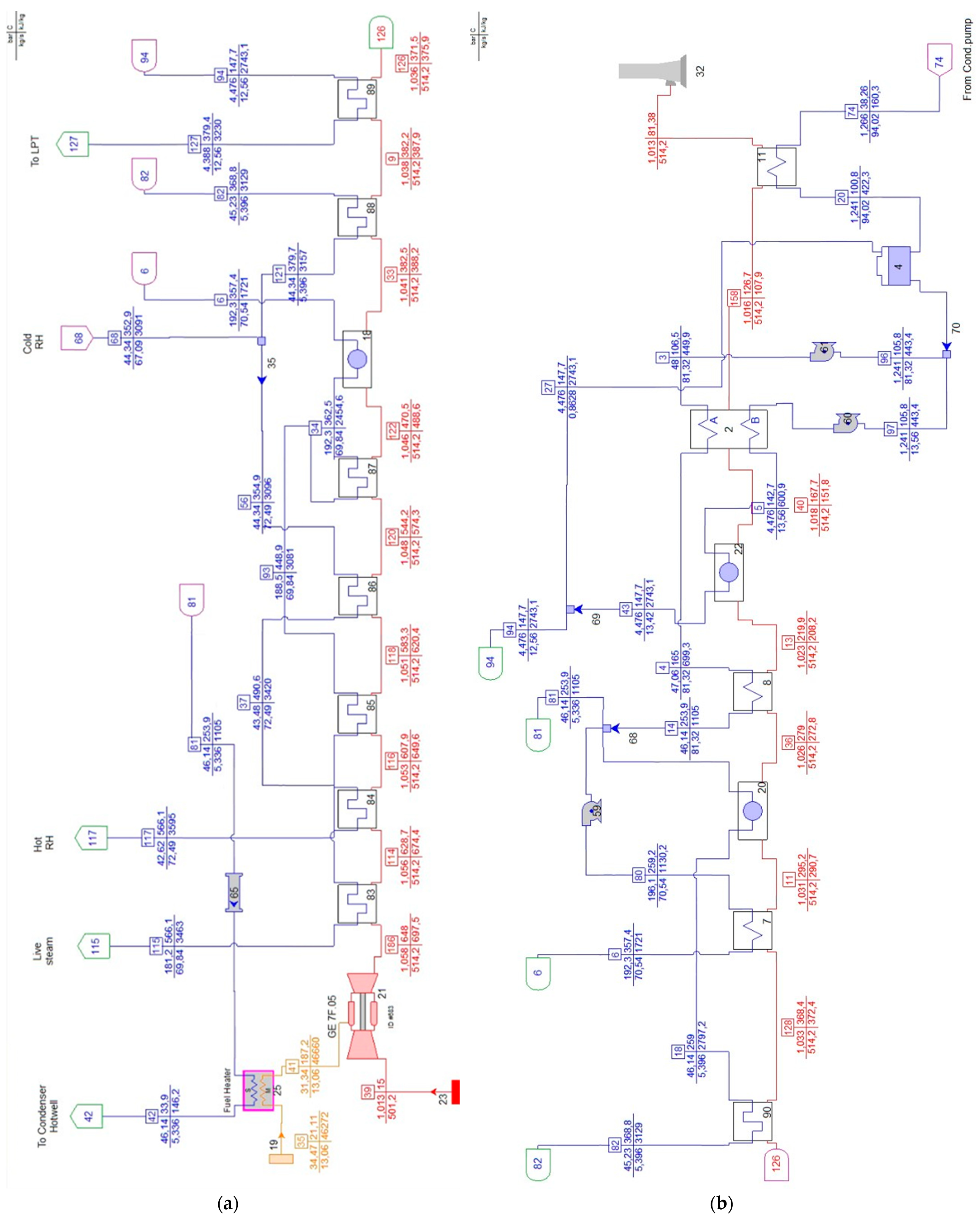
This configuration, hereafter referred to as “3PRH”, comprises two GE 7F.05 gas turbines, two triple-pressure HRSGs with reheat (RH), and one condensing ST. The 2 × 1 CC produces a net power output (PCC,n) of 708.9 MW, with a net electric efficiency (ηCC,n) of 58.6%, when fed by NG (Table 1). Gross power (PCC,g) amounts to 727.2 MW with a gross electric efficiency (ηCC,g) of 60.1%. The nominal gross power of each GT is PGT,g = 239.3 MW, with a gross efficiency of ηGT,g = 39.6%. The ST is divided into three sections (high pressure (HP), intermediate pressure (IP), and low pressure (LP)), with a capacity of 251.5 MW. The exhausted steam is condensed to saturated liquid in a water-cooled condenser. The water makeup is due to blowdown and steam leakages through the ST assembly. Each HRSG consists of three evaporators, eight superheaters, and four economizers: the exhaust gases are sent to the stack at 81.5 °C. Additional design parameters of GT and ST are listed in the second column of Table 2, and the layout is depicted in Figure A1 and Figure A2. Moreover, fuel pre-heating is configured by harnessing the heat from a fraction of the IP hot water. This configuration has already been used for various previous research on decarbonization [31,32], as it is indicative of a modern, high-efficiency CC.
The part load behavior was based on modulating both inlet guide vanes (IGVs) and turbine inlet temperature (TIT) to keep the turbine outlet temperature (TOT) nearly constant (Figure 1a). This was successful as long as the GT load does not fall below 30%: TIT is reduced and IGVs close to diminish the GT inlet air. Further load reduction, below 30%, can only be accomplished by lowering the TOT due to fully closed IGVs and decreased fuel flow. The alternative strategy that relies on TIT (hence fuel flow) control with constant nominal intake air would result in a decreasing TOT trend, thus leading to lower values of ηCC,n (Figure 1b). Therefore, TOT control was applied in the modeling for the entire load range: the loss in ηCC,n was found to be within 3.6 pp at half load, which is actually lower than that reported in [22,23,24]. Note that the minimum GT load was extended up 20% in accordance with the manufacturer’s specifications: the corresponding loss in ηCC,n is 13.4 pp. Consistent with the TOT target profile shown in Figure 1a, a decreasing mass flow rate of exhaust gas exits the HRSG at a reduced temperature while diminishing the GT load (Figure 2a): at minimum turndown, 268 kg/s of flue gas is discharged at about 70 °C. XCO2 in the flue gas decreases from 4.3% to 3% vol, as indicated by the labels in Figure 2a. Purely sliding pressure operation down to the GT 20% load is confirmed in Figure 2b, where inlet pressure for each turbine stage decreases linearly with load.

2.2. NGCC with Double-Pressure HRSG

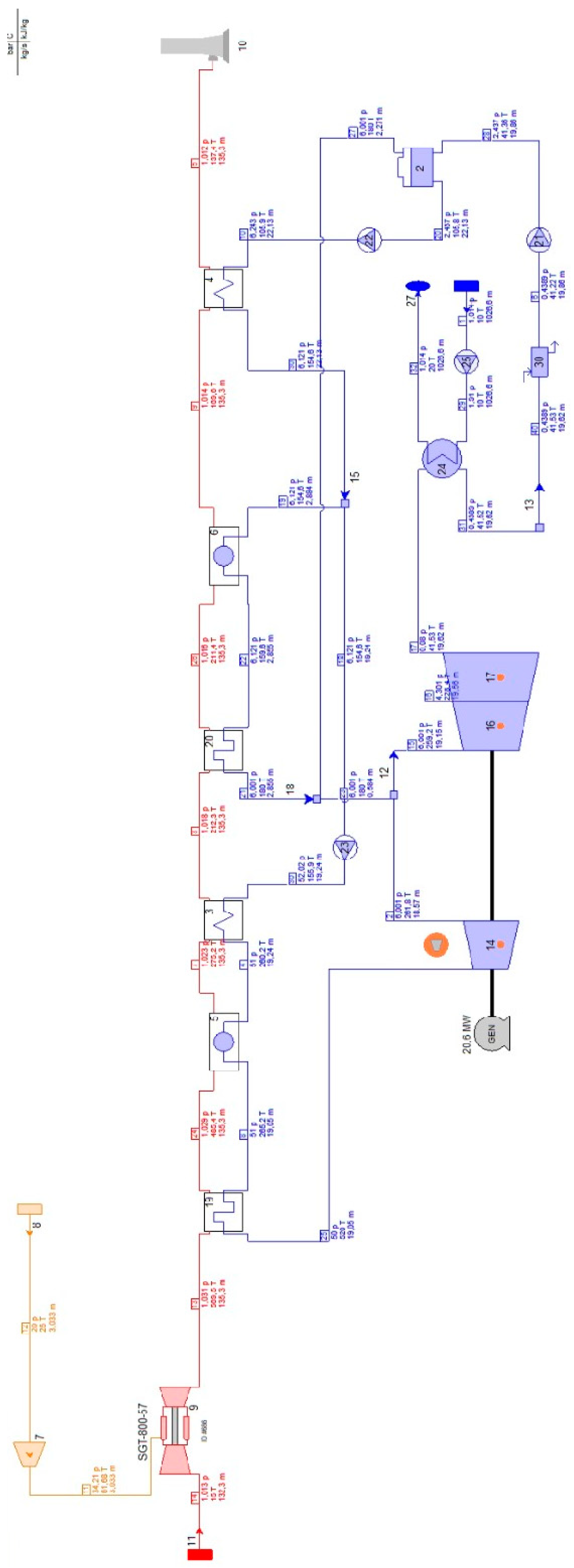
This configuration, hereafter referred to as “2P”, is based on a SGT-800 gas turbine with rated PGT,g of 55.5 MW and ηGT,g of 39.5%. The steam cycle comprises HP and LP steam turbines, a condensing system, and a two-pressure-level HRSG. A net power production of PCC,n = 74.5 MW is achieved with a ηCC,n of 53.1%. These values are consistent with the most common application of 2P CC systems used to produce low to medium power [33]. Note that RH is not present because it is sparsely used in 2P plants. Gross performance are the following: PCC,g and ηCC,g equal 76.1 MW and 54.2%, respectively. The ST capacity is 21.1 MW, thus contributing 27% to the PCC,g. The HRSG, which consists of a dual superheater-evaporator-economizer sequence, allows the exhaust gas stream to be cooled to 137.4 °C. Further design parameters of GT and ST are listed in the third column of Table 2, and the layout is depicted in Figure A3.
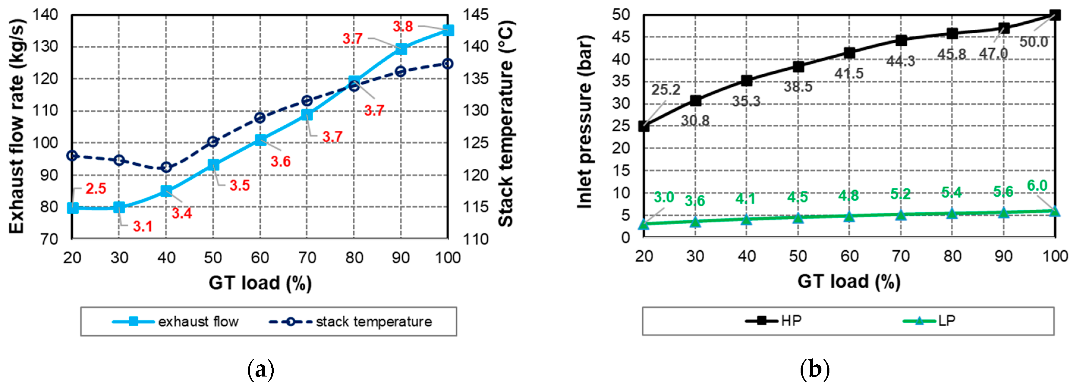
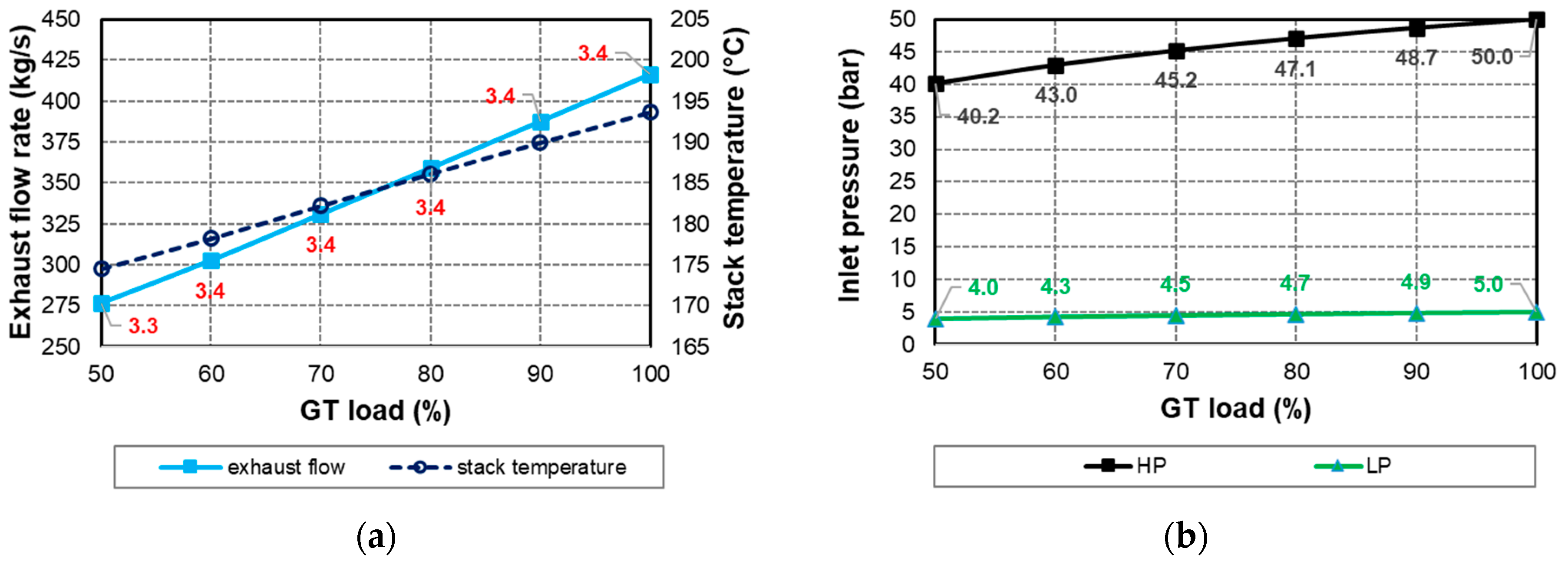
Consistent with what was explained in Section 2.1, partial-load control was adopted to combine the progressive closure of IGVs with the reduction of fuel input to obtain a desired TOT profile (Figure 3a). Unlike the previous case, an increase in TOT beyond the nominal value was allowed while remaining within the threshold of about 30 °C. Therefore, the maximum TOT value of about 600 °C is reached when the GT load is reduced to 60% and maintained until the GT load is within 40%. For further load reduction, TOT decreases with TIT, given the minimum amount of inlet air guaranteed by the fully closed IGVs. The profile of ηCC,n is better than that of a similar “NGCC-2P” case available in the published literature [34], of comparable size, i.e., 80 MW (Figure 3b). Nevertheless, the penalty in ηCC,n grows as the load decreases: it stays within 5.4 pp at half load and exceeds 10 pp when the GT load is less than 30%. Figure 4a provides information on the declining amount of exhaust gas discharged from the HRSG at temperatures dropping to about 122 °C if GT load ≤ 40%. However, stack temperatures are always higher than those in 3PRH case, given the less effective HRSG arrangement. The sliding pressure operating curve is reported in Figure 4b for both HP and LP turbine stages.

2.3. NGCC with Single-Pressure HRSG

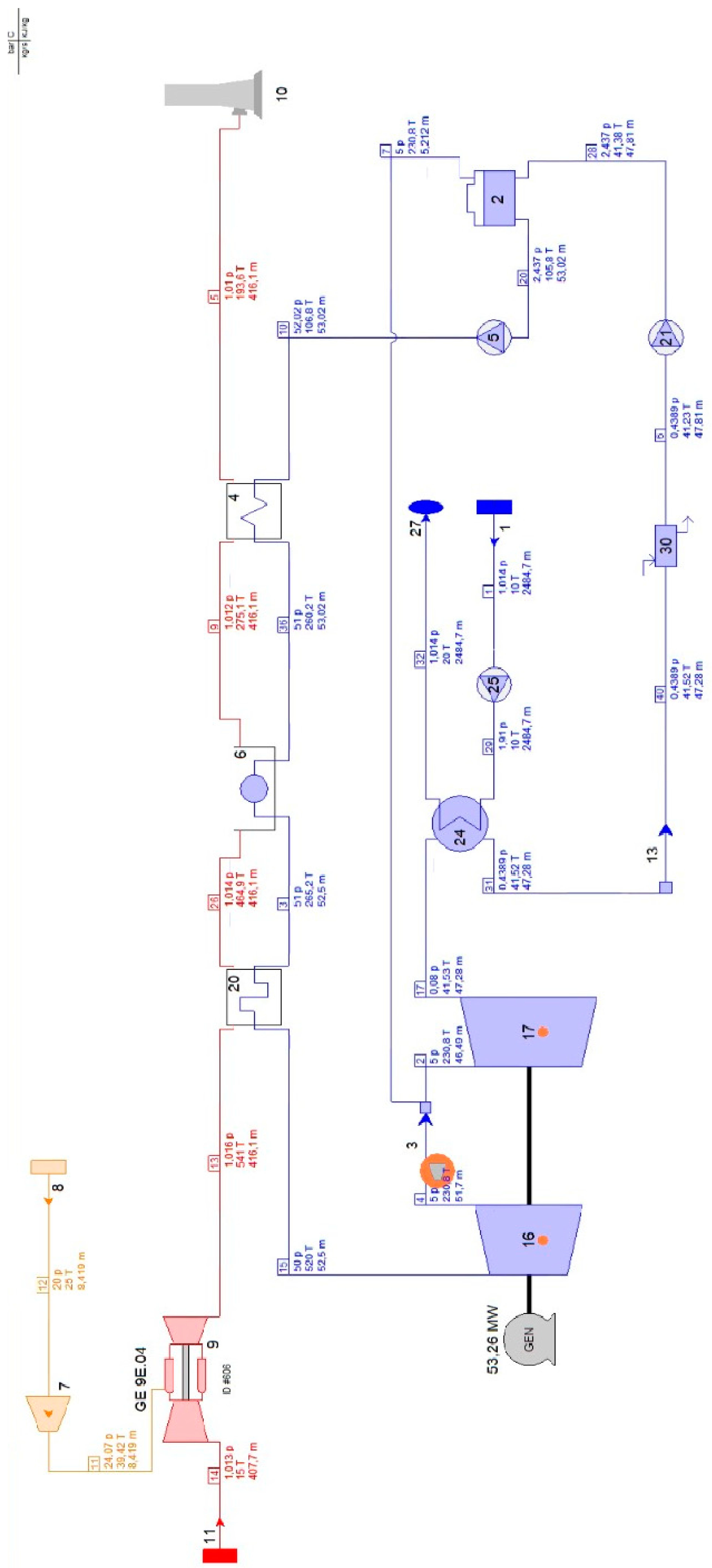
This configuration, hereafter referred to as “1P”, is the simplest. The characteristics of the GT mimic those of the GE 9E.04, with a nominal PGT,g of 148.6 MW and ηGT,g of 37.6%. The ST includes HP and LP stages with an intermediate steam extraction to preheat feedwater in a deaerator, as shown in Figure A4. The thermal power cycle is completed by a water-cooled condenser. The contribution of ST to the total PCC,g, of 199.7 MW is 27%. Total plant auxiliaries are about 3.5 MW, so the PCC,n is 196.2 MW. With a ηCC,n of 50.4%, this is the worst case because of less heat being recovered from the flue gas through the HRSG, which consists of a superheater-evaporator-economizer block. It follows that the exhaust outlet temperature is the highest, which is 193.6 °C. Additional design parameters of GT and ST are listed in the 4th column of Table 2.
IGVs are closed progressively until the GT load is reduced to 50%, a condition close to minimum turndown of 46%. Accordingly, TOT gradually increases due to load reduction to the recommended limit of about 50 °C above the nominal value [35]. To restrict TOT growth, TIT is maintained at about the nominal value at GT load ≥ 80% but then is slightly reduced at lower loads (Figure 5a). The resulting values of ηCC,n are higher than those in [36], for a “NGCC-1P” of comparable size, i.e., 218.6 MW (Figure 5b). Nevertheless, ηCC,n decreases by 4.7 pp at half GT load. Both mass flow rate and temperature of the flue gas exiting the HRSG decrease linearly with GT load: the latter drops by about 20 °C at half load (Figure 6a).
However, stack temperatures are the highest among the cases analyzed. The sliding pressure curve is reported in Figure 6b for both HP and LP turbine stages, with the former providing the steam production condition. As expected, live steam parameters decrease with the reduction of GT load.

3. Description and Modelling of the CO2 Capture Unit

Exhaust gases leaving the HRSG enter the PCC unit, which was modeled according to the same approach used in [32]. For clarity, the most relevant features of 30 wt% MEA-based chemical absorption process are mentioned here, starting from the simplified layout of Figure 7. In all cases, flue gases are cooled to 40 °C before entering the absorber, from which they are discharged at 45 °C; 90% of the CO2 contained in the inlet flue gas is captured. This capture rate was chosen because it is the current standard for CCS-equipped power and industrial plants operating today [37]. CO2-rich solvent exiting from the bottom of the absorber is pumped through a heat exchanger where it is preheated with hot lean solvent and then sent to the stripper to desorb CO2. The regeneration heat is obtained from the steam extracted upstream of the LP turbine stage to reduce ST power loss and meet temperature and pressure requirements of the reboiler. The hot lean solvent is cooled before recycling back into the top of the absorber tower. CO2 and water vapor leaving the top of the stripper enter a condenser to condense the water vapor and send it back into the stripper. The resulting CO2 stream, available at 1.7 bar and 40 °C, is then compressed to 150 bar by a five-stage intercooled compressor with 85% isentropic efficiency. At each compressor inlet, the gas stream is cooled down to 35 °C using cooling water supplied at 15 °C. A blower, with 85% isentropic efficiency, is placed upstream of the absorber compensates for pressure losses.
Although the quality of steam extracted upstream of the LP ST varies depending on the CC layout, the reboiler operation was set at about 3 bar and 133 °C in all cases (2.965 bar and 133.1 °C, calculated from saturated steam properties). Therefore, a throttling valve, with a downstream set point of 2.965 bar, and a desuperheater, with a specified maximum outlet temperature of 140 °C, were included in the model to adapt LP steam conditions (pressure and temperature, respectively) to the reboiler constraints (Figure 8). The cooling water for the desuperheater is taken downstream of the HP pump whatever the case. The extracted steam returns to the steam cycle from the reboiler as condensate at an appropriate point to minimize the temperature difference from the main condensate stream: at the deaerator inlet in the 3PRH case or at the deaerator outlet in the 2P and 1P cases.
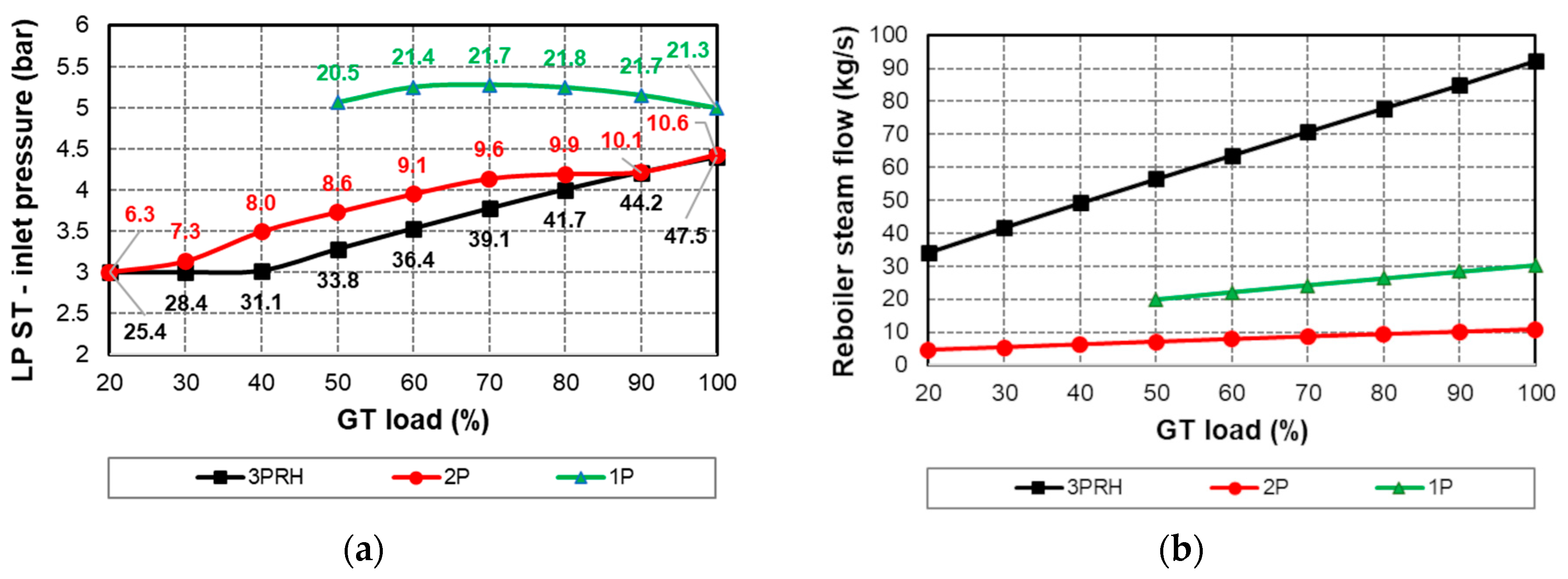
Considering that LP turbine inlet pressure is expected to decrease at part load, as is clearly evident from Figure 2b, Figure 4b, and Figure 6b, a throttling valve was inserted upstream of the LP turbine stage for inlet pressure control, with a set point of 3 bar. So, steam is supplied to the reboiler at a sufficiently high pressure, regardless of the load, at the expense of throttling losses. To reduce them, a multi-sector valve (four sectors) was set: the minimum pressure drop is 2.5% of the inlet pressure, when the valve is fully open.
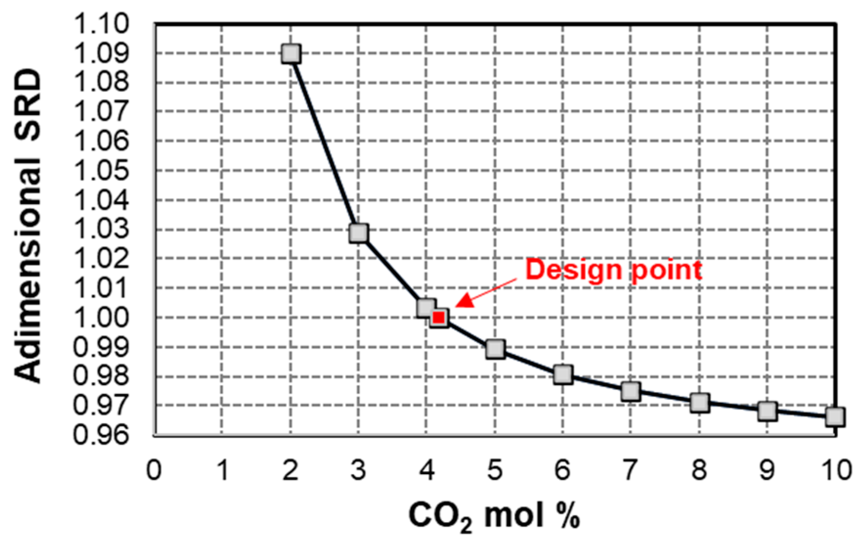
It should be mentioned that the chemical reactions in the highly non-ideal MEA–CO2–H2O system were not modelled but SRD was correlated to XCO2 in the exhaust gas, as suggested in [38]. Given the goal of 90% capture efficiency, SRD follows a decreasing asymptotic trend, from the nominal value of 3.3 MJ/kg at the corresponding full-load XCO2 (see the red square in Figure 9) to significantly lower values when XCO2 is above 7–8%. More generally, the sizing of the PCC unit was based on exhaust gas conditions at full load, knowing that, at reduced loads, the gas to be treated decreases in terms of flow rate, temperature, and XCO2, as shown in Figure 2a, Figure 4a, and Figure 6a. Further design parameters related to the capture process are collected in Table 3.

4. Performance Prediction of NGCC Power Plants with CO2 Capture

For each case considered, power plant operation at part load was assessed, paying attention to the effects of integrating the capture unit into the NGCC layout on overall performance. Power losses and consumptions due to PCC were estimated along with SRD. The price to be paid, in terms of reduced ηCC,n, was evaluated in combination with final CO2 emission intensity (EI).

4.1. Sources of Energy Loss

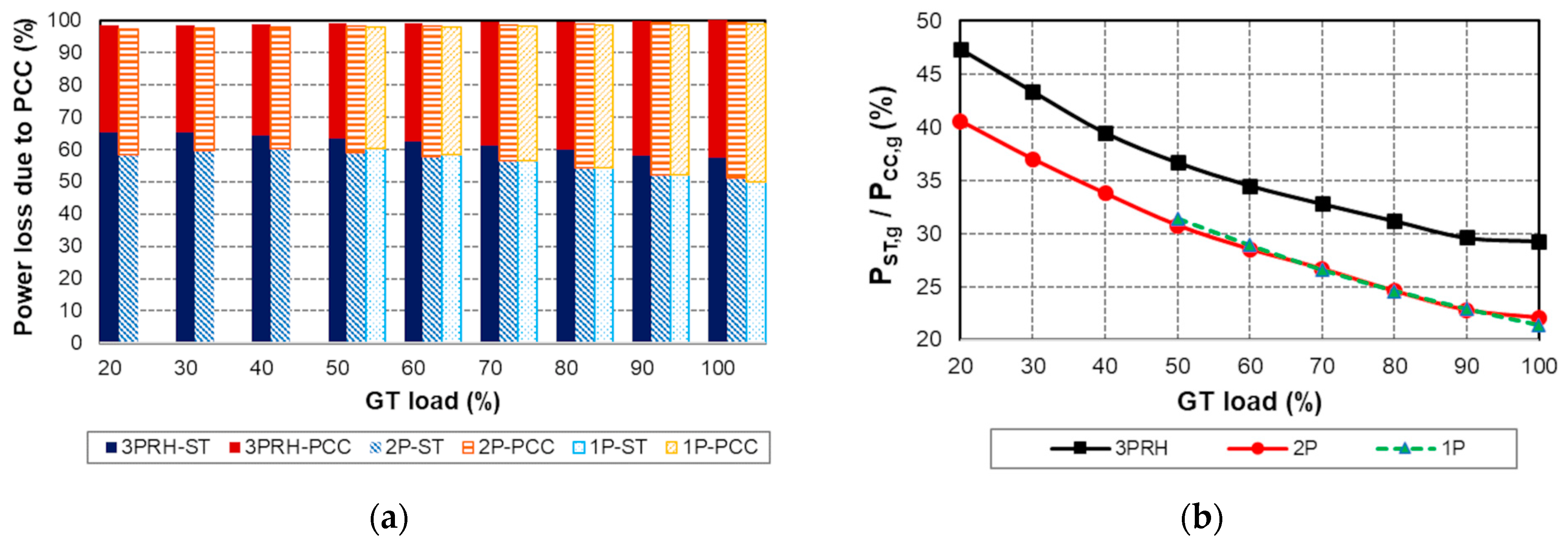
It is well known that the reduction in PCC,n due to the application of the post-combustion decarbonization is mainly caused by the electrical consumption of the PCC unit on the one side and, on the other side, by the decrease in ST turbine power due to the lower steam flow rate entering the LP stage to meet MEA regeneration. These two sources of power loss have been quantified as percentages in Figure 10a (the remaining small fraction to reach 100% is covered by auxiliaries). Of the two, the latter is generally more significant than the former, regardless of CC layout and GT load. However, ST shares decrease in favor of PCC shares while raising the GT load due to the increase in the exhaust flow to be processed. The burden of ST nonproduction is the highest in the 3PRH case compared with the 2P and 1P cases: it reaches a maximum of 65.3% at minimum load and falls to 57.5% at full load. Even in the 1P case, the ST fraction is still the majority, varying from about 50% at full load to 60% at half GT load. Indeed, the contribution of ST to CC power output grows at part load, whatever the layout, but the role played by the bottoming cycle is more relevant where heat recovery from flue gas is more effective, i.e., in 3PRH (Figure 10b). In this case, the fraction of power delivered by ST to the total exceeds that of 2P and 1P by 6–7 pp.
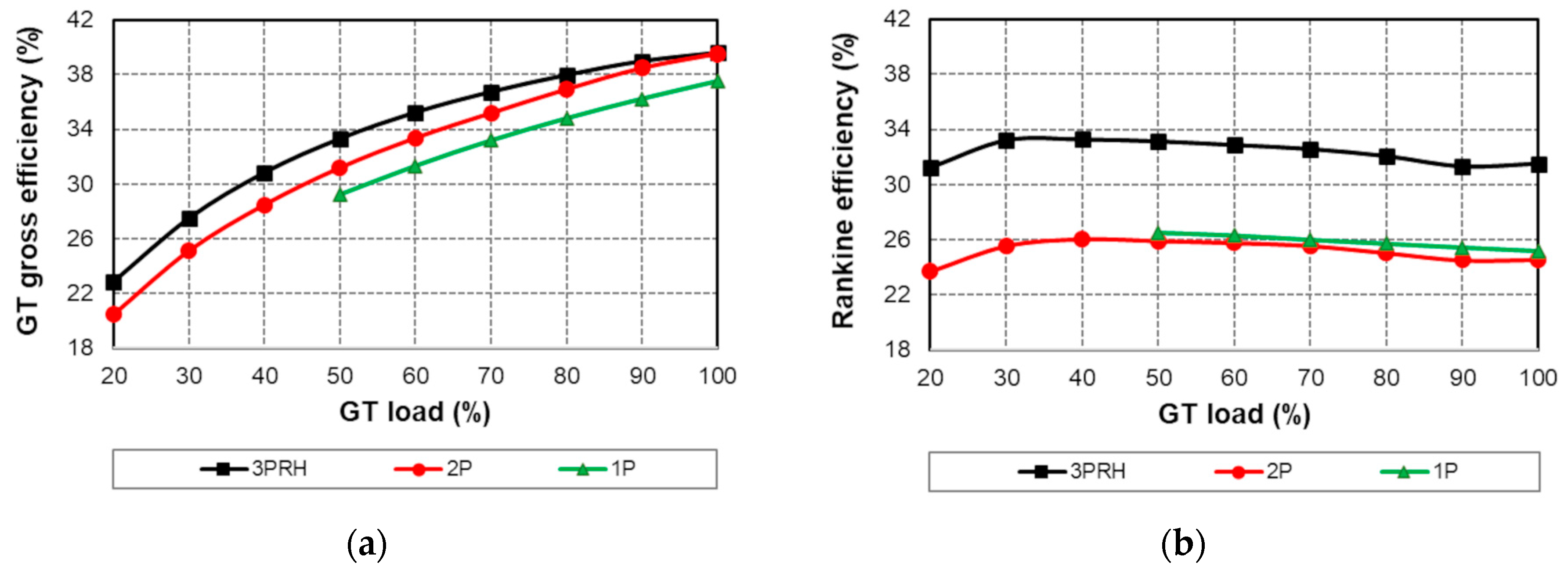
For better understanding, Figure 11 compares the topping and bottoming cycles. In Figure 11b, Rankine cycle efficiency (ηR) in the 3PRH layout, ranging from 31.2% to 33.3%, is higher than that in 2P/1P by about 7–8 pp, in line with Figure 10b. In all cases, the bottoming cycle maintains a good near-constant efficiency at part load, unlike the GT (Figure 11a), which suffers from a penalty that depends on the control strategy illustrated in Section 2. For this reason, CC power generation increasingly relies on ST as GT load is lowered. This is particularly advantageous in the 3PRH case, since ηR is much larger than ηGT,g at loads below 50%. Obviously, each curve in Figure 10b would shift upward, with the same trend, by 5–6 pp without CO2 capture, thus emphasizing the dominant role of the bottoming cycle over the topping one, in full accordance with [32].
The quality of steam sent to the stripper was guaranteed under all conditions. In fact, the steam pressure at the LP stage inlet is greater than or equal to the 3-bar threshold, as shown in Figure 12a. Indeed, throttling of the inlet control valve is only necessary when the GT load is less than 50% in the 3PRH layout. Then, with the help of valve #33 and component #51 in Figure 8, the reboiler is fed with a constant-pressure (and -temperature) steam flow at 2.965 bar (and 140 °C). This is consistent with the recommendation of Fernandez et al. [39] to ensure that the final operating temperatures in the reboiler are close as possible to the design value so as to preserve a favorable vapor–liquid equilibrium for desorption, thus reducing SRD at low loads. Inlet pressure at LP ST, with the control valve fully open, is proportional to the inlet steam flow rate, which roughly corresponds to the difference between the total amount of steam produced in the HRSG and that required by the reboiler (neglecting ST leakages). The former is case-specific because it depends on the waste heat from the GT exhaust flow, which in turn is a function of the GT control strategy, while the latter increases linearly with GT load in all cases, as shown in Figure 12b. This is in full agreement with [22]. In parallel, solvent consumption grows linearly with GT load, and thus with CO2 captured, confirming the results reported in [16].
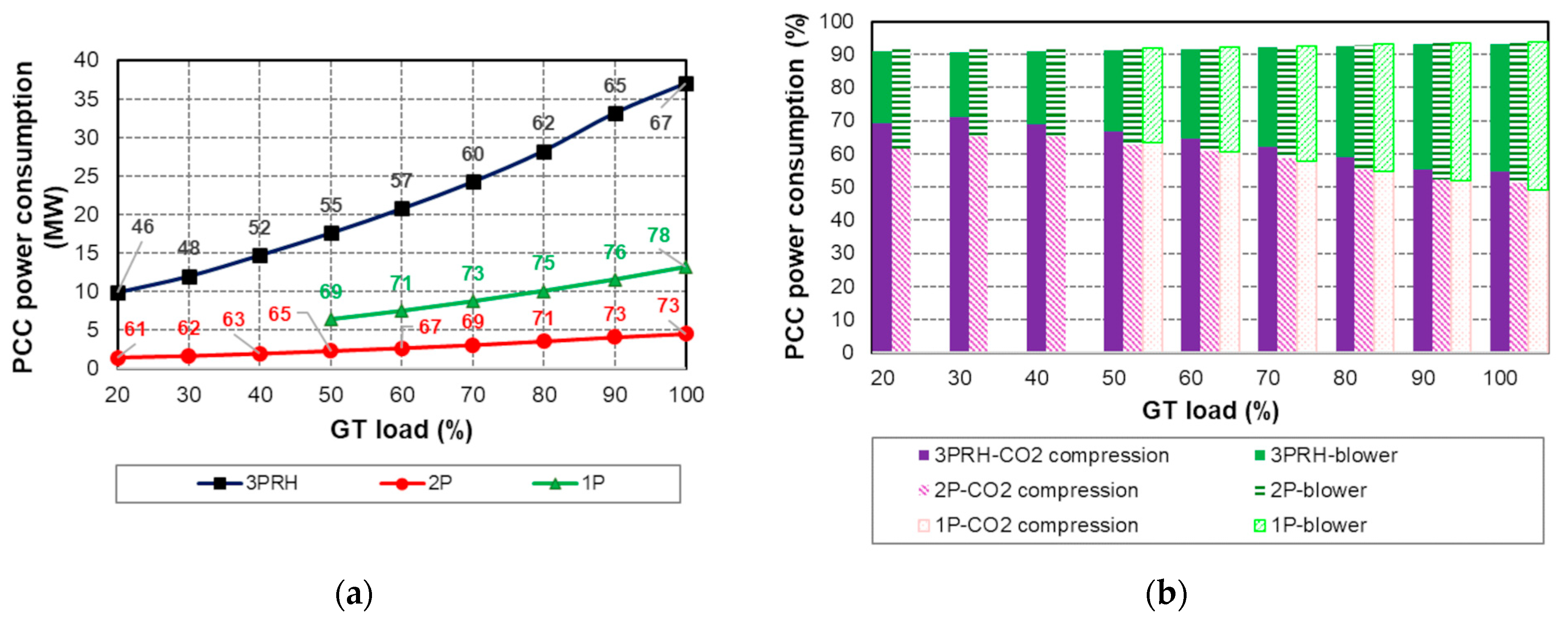
Returning to PCC power consumption, its total amount scales with the size of the power plant and increases with GT load (Figure 13a): values of 37, 4.6 and 13.2 MW at full load for the 3PRH, 2P, and 1P cases, respectively, drop to 10, 1.4, and 6.4 MW at minimum load. However, when divided by the total auxiliary consumption, the resulting percentage shares (see labels in Figure 13a) reveal that the PCC burden becomes heavier as the complexity of the power plant decreases: thus, the best case is 3PRH, with percentages between 46 and 67% while the worst case is 1P, with percentages between 69 and 78%. Whatever the case, the largest contributor to capture-related consumption is the CO2 compression train, followed by the blower. For both items, the magnitude of power input is proportional to the flow rate of the exhaust gas to be treated and thus decreases with load reduction. However, Figure 13b shows that their shares reflect the GT control strategy, which ultimately affects the amount of reduction in flue gas at part load. Comparing the three layouts, at GT load within 50%, it is clear that CO2 compression becomes increasingly important moving away from the design point, reaching maximum shares of about 70%. Together, the two items cover more than 90% of the total power consumed by PCC: the remaining fraction includes the consumption of the pump for solvent circulation and some minor items.
The impact of PCC on CC operation was further assessed in terms of SRD (Figure 14a). The modeling predictions were compared with the results contained in [23,24,25], which refer to a three-level pressure configuration. In this study, SRD is roughly constant at GT load > 50%. However, its value is slightly different as the layout varies: it is 3.29, 3.32, and 3.34 MJ/kg CO2 for the 3PRH, 2P, and 1P cases, respectively. The lower the SRD, the higher the XCO2 in flue gas, the levels of which are around 4.1, 3.7, and 3.4% vol, respectively (see labels in Figure 2a, Figure 4a, and Figure 6a). The SRD profiles derived from the literature are also almost flat but stand at higher values, between 3.6 and 3.7 MJ/kg CO2. In fact, the energy consumption of the MEA process for the standard 90% capture rate has been set at 3.8 MJ/kg CO2 as a benchmark for alternatives [40]. Nevertheless, it is recognized that this value is significantly overestimated compared with the results obtained from proprietary advanced amine solvents tested in recent years [41]. Even experimental parametric tests with 30 wt% MEA revealed regeneration energy between 2.3 and 3.7 MJ/kg CO2, with the lowest values recorded at the stripper pressures of 2.5 and 3.5 bar [42]. Therefore, the simulated SRD is consistent with the recent evolution of technology toward reducing thermal energy demand. At GT load < 40%, SRD increases significantly to 3.4–3.5 MJ/kg CO2 in the 3PRH/2P cases as a consequence of further CO2 dilution to very low concentrations of 3/2.5% vol. Indeed, lowering the air–fuel ratio can help increase XCO2 in the exhaust, thus reducing the SRD, as appears from a simple comparison between Figure 14a,b.

4.2. Net Electric Efficiency and CO2 Emission Intensity

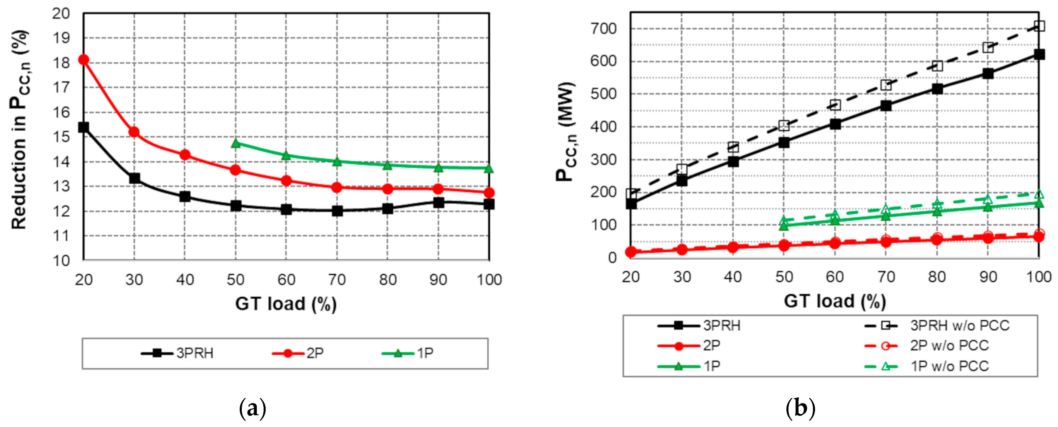
The penalty caused by PCC was quantified in terms of percentage reduction (∆%) in PCC,n (Table 4, Figure 15a) and loss in ηCC,n (∆) (Table 5, Figure 16a), as in the published literature. The obvious linear reduction of PCC,n with decreasing GT load is confirmed by the values reported in Table 4 and plotted in Figure 15b. The difference in PCC,n in each row (at the same GT load), with and without PCC, increases with power plant size for the reasons explained in Section 4.1. Thus, in descending order, the ranking is as follows: 3PRH, 1P, and 2P. However, ∆% in PCC,n indicates that 3PRH is the best whereas 1P is the worst (Figure 15a). In fact, at GT load > 50%, the former is characterized by ∆% of about 12% while the latter has ∆% of almost 14%. The 2P case lies in between, with ∆% of 13%. At lower loads, ∆% rises sharply to just over 15% and 18% in the 3PRH and 2P cases, respectively. The point is that SRD plays a key role in determining the ∆% in PCC,n, as can be easily deduced by comparing Figure 15a with Figure 14a: the greater the SRD, the heavier the ∆% in PCC,n. In fact, SRD was found to be the parameter that most influences the NGCC net output, according to the sensitivity analysis performed in [43] for a 3PRH layout.
As regards ηCC,n, complexity of the thermal plant goes hand in hand with performance, even when PCC is adopted (Figure 16b). In fact, profiles with PCC shift downward from those of the non-decarbonized plants (see dashed lines), but preserving the arrangement in descending order of ηCC,n, i.e., 3PRH, 2P, and 1P, throughout the investigated load range. At full load, ηCC,n of 51.4, 46.3, and 43.4, respectively, falls to 38.3, 30.1, and 38.9 at minimum load. This is an important difference from [30], in which a 3PRH layout with PCC was always less efficient than the corresponding 2P case (with RH). For a further verification, outcomes from previously published works were added to Figure 16a (see dashed lines). In all cases in this study, ηCC,n loss is at the minimum approximately when the GT load is low enough to reach the fully closed IGV condition. From this operating point, increasing the GT load to reach the nominal condition results in a slight increase in ηCC,n penalty, which reaches a maximum at full load, consistent with the gradual increase in the exhaust flow sent to the PCC unit. Operation at very low loads also causes a growth in ηCC,n loss relative to the minimum, although to a lesser extent than at the design point, due to the drop in flue gas CO2 content. Given this general behavior, the penalty in ηCC,n is between 6.5 and 7.2 pp. Although it is underestimated, compared to [22,24], as a consequence of the lower SRD (see Figure 14a), the trend is fully verified: in fact, GT part load strategy in [22,24] is similar to that assumed here. It is also reassuring that the latest revision of the NETL report [44] confirms the validity of the predictions in Figure 15a and Figure 16a, at least at full load: for two 3PRH CC systems, different in size, ∆% in PCC,n was found to be 12%, with a loss in ηCC,n of 7 pp.
From Figure 16a, it can be deduced that the 2P layout is associated with the smallest penalty in ηCC,n, from 6.5 to 6.8 pp: it performs better not only than the 1P case, with a benefit within 0.2 ÷ 0.3 pp, but also than the 3PRH layout, with an advantage that becomes more substantial as GT load increases, up to 0.44 pp at rated load. This occurs at the same steam extraction pressure from the LP ST as in the 3PRH case, for which the loss in ηCC,n varies between 6.7 and 7.2 pp.
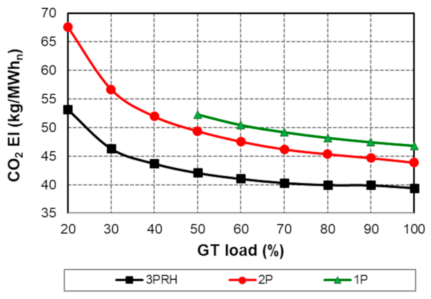
With the 90% capture target always achieved, the resulting values of CO2 EI are presented in Table 6 for each layout for direct comparison with the corresponding levels without PCC. Figure 17 focuses on decarbonized power plants, in which EI is between 40 and 68 kg/MWh instead of 350–550 kg/MWh. It was verified that EI, defined as the ratio of CO2 mass flow rate at the stack to PCC,n as in [31,32], is consistent with data from similar calculations [45]. In all cases, the lower the GT load, the higher the EI, with the most significant increase in EI occurring at GT loads below 40%. This is due to the CC efficiency degradation at part load. Since EI is inversely related to ηCC,n, the least-performing IP case produces the highest EI values, up to 52 kg/MWh at half load. This is followed, with decreasing EI, by the 2P and 3PRH cases. For the latter, the GT load can be halved while maintaining the EI within 42 kg/MWh.

5. Conclusions

The detrimental effects of 90% amine-based CO2 capture on the performance of three different NGCC power plants with three-, two-, and one-pressure-level HRSG were estimated through thermodynamic modelling. On the one hand, steam from bottoming Rankine cycle for solvent regeneration was always available at the condition dictated by the reboiler regardless of the CC layout and GT load (20% to 100%). On the other hand, a percentage reduction of 12% in PCC,n and a loss of 7 pp in ηCC,n should be taken into account, in agreement with [44].
However, GT regulation strategy at part load affects the properties of the exhaust gas to be treated (temperature, mass flow rate, and CO2 concentration) and ultimately the SRD, which has the greatest effect on the lost power. Therefore, the smallest reduction in PCC,n of 12%, for the 3PRH layout, can be achieved when GT is operated at the lowest (possible) air–fuel ratio for each load.
Regarding ηCC,n, although full load is characterized by the highest penalty (from 6.8 to 7.2 pp), considerable levels of loss are still associated with very low loads (from 6.7 to 7.0 pp), whatever the CC configuration. The penalty in ηCC,n decreases when the efficiency of the topping cycle is higher than that of the bottoming cycle, a condition that occurs in a less complex HRSG configuration. At best, ηCC,n loss is about 6.5 pp for the 2P case, where ηGT,g exceeds ηR in the widest GT load range.

Author Contributions

Conceptualization. S.R.; methodology and formal analysis. E.S. and S.R.; validation and simulation. E.S.; writing—original draft preparation. E.S. and S.R.; writing—review and editing. S.R.; supervision. S.R. All authors have read and agreed to the published version of the manuscript.

Funding

This research received no external funding.

Data Availability Statement

The datasets presented in this article are not readily available because of limitations due to software licensing.

Conflicts of Interest

The authors declare no conflicts of interest.

Abbreviations

CCCombined cycle
CCSCarbon capture and storage
EIEmission intensity
GTGas turbine
HPHigh pressure
HRSGHeat recovery steam generator
IGVInlet guide vane
IPIntermediate pressure
ISOInternational Standards Organization
LPLow pressure
MEAMono-ethanolamine
NGNatural gas
NGCCNatural gas combined cycle
PPower
PCCPost-combustion capture
ppPercentage points
RHReheat
SRDSpecific reboiler duty
STSteam turbine
TITTurbine inlet temperature
TOTTurbine outlet temperature
volBy volume
XMolar concentration
wtWeight
∆%Percentage difference
ηThermal efficiency
3PTriple-pressure HRSG
2PDouble-pressure HRSG
1PSingle-pressure HRSG
Subscripts
ggross
nnet
RRankine

Appendix A

Figure A1. Layout of the NGCC with triple-pressure HRSG: GT and HRSG divided into (a) first and (b) second sections.
Energies 17 03501 g0a1
Figure A2. Layout of the NGCC with triple-pressure HRSG: steam turbine and water-cooled condenser.
Energies 17 03501 g0a2
Figure A3. Layout of the NGCC with dual-pressure HRSG.
Energies 17 03501 g0a3
Figure A4. Layout of the NGCC with single-pressure HRSG.
Energies 17 03501 g0a4

Appendix B

For each component, steady-state heat and mass balances were solved based on inputs, resulting in an algebraic system of equations. Parameters such as pressure, temperature, enthalpy, and mass flow rate were calculated until their values converge on a final solution, with a tolerance within 10−4. Power convergence was within 0.01%. Iterations are grouped into a number of 200 for at least four consecutive loops.
GT models are consistent with vendor information; data sources are as follows:
  • GE 7F.05: GE GTP Web 4.42.0 (7F.05-1016T-L3) 06/2017.
  • SGT-800: Siemens SIPEP 5.14.0 (07/2018).
  • GE 9E.04: GE GTP Web 4.23.0 (9E.04-PRODCAT2016) 04/16.
For steam turbines, the group overall efficiency is computed from the isentropic efficiency set by the user, in the range from 80% to 92%. This compares the actual enthalpy change of the steam with the enthalpy change associated with an ideal, reversible (constant entropy) expansion of the steam from the same inlet state to the same exit pressure.
For any heat exchanger, the total heat transfer rate is given by the product of overall heat transfer coefficient, effective surface area, and log mean temperature difference between the hot and cold fluids. Further details are available in [35].

References

  1. IPCC. 2023: Sections. In Climate Change 2023: Synthesis Report. Contribution of Working Groups I. II and III to the Sixth Assessment Report of the Intergovernmental Panel on Climate Change; Core Writing Team, Lee, H., Romero, J., Eds.; IPCC: Geneva, Switzerland, 2023; pp. 35–115. [Google Scholar] [CrossRef]
  2. Mirzabaev, A.; Kerr, R.B.; Hasegawa, T.; Pradhan, P.; Wreford, A.; von der Pahlen, M.C.T.; Gurney-Smith, H. Severe climate change risks to food security and nutrition. Clim. Risk Manag. 2023, 39, 100473. [Google Scholar] [CrossRef]
  3. IEA. CO2 Emissions in 2022. 2023. Available online: https://www.iea.org/reports/co2-emissions-in-2022 (accessed on 19 April 2024).
  4. Nivard, M.; Smeets, B.; Tryggestad, C.; van de Giessen, P.; van der Meijden, R. Global Energy Perspective 2023: CO2 emissions outlook. McKinsey Energy Solutions. 2024. Available online: https://www.mckinsey.com/industries/oil-and-gas/our-insights/global-energy-perspective-2023-co2-emissions-outlook (accessed on 21 April 2024).
  5. IEA. CO2 Emissions in 2023. 2024. Available online: https://www.iea.org/reports/co2-emissions-in-2023 (accessed on 22 April 2024).
  6. IEA. World Energy Outlook 2023. Available online: https://www.iea.org/reports/world-energy-outlook-2023 (accessed on 23 April 2024).
  7. IEA. Electricity 2024. Available online: https://www.iea.org/reports/electricity-2024 (accessed on 24 April 2024).
  8. Global CCS Institute. The Global Status of CCS: 2023. In Scaling Up through 2030; Global CCS Institute: Melbourne, Australia, 2023. [Google Scholar]
  9. Fattouh, B.; Muslemani, H.; Jewad, R. Capture Carbon. In Capture Value: An Overview of CCS Business Models; Oxford Institute for Energy Studies: Oxford, UK, 2024; ISBN 978-1-78467-228-7. [Google Scholar]
  10. Dziejarski, B.; Krzyżyńska, R.; Andersson, K. Current status of carbon capture. utilization. and storage technologies in the global economy: A survey of technical assessment. Fuel 2023, 342, 127776. [Google Scholar] [CrossRef]
  11. Madejski, P.; Chmiel, K.; Subramanian, N.; Kuś, T. Methods and techniques for CO2 capture: Review of potential solutions and applications in modern energy technologies. Energies 2022, 15, 887. [Google Scholar] [CrossRef]
  12. Wang, N.; Wang, D.; Krook-Riekkola, A.; Ji, X. MEA-based CO2 capture: A study focuses on MEA concentrations and process parameters. Front. Energy Res. 2023, 11, 1230743. [Google Scholar] [CrossRef]
  13. Karayil, A.; Elseragy, A.; Aliyu, A.M. An Assessment of CO2 Capture Technologies towards Global Carbon Net Neutrality. Energies 2024, 17, 1460. [Google Scholar] [CrossRef]
  14. Buvik, V.; Høisæter, K.K.; Vevelstad, S.J.; Knuutila, H.K. A review of degradation and emissions in post-combustion CO2 capture pilot plants. Int. J. Greenh. Gas Control. 2021, 106, 103246. [Google Scholar] [CrossRef]
  15. Vega, F.; Baena-Moreno, F.M.; Fernández LM, G.; Portillo, E.; Navarrete, B.; Zhang, Z. Current status of CO2 chemical absorption research applied to CCS: Towards full deployment at industrial scale. Appl. Energy 2020, 260, 114313. [Google Scholar] [CrossRef]
  16. Subramanian, N.; Madejski, P. Analysis of CO2 capture process from flue-gases in combined cycle gas turbine power plant using post-combustion capture technology. Energy 2023, 282, 128311. [Google Scholar] [CrossRef]
  17. Zhao, K.; Jia, C.; Li, Z.; Du, X.; Wang, Y.; Li, J.; Yao, Z.; Yao, J. Recent advances and future perspectives in carbon capture. transportation. utilization. and storage (CCTUS) technologies: A comprehensive review. Fuel 2023, 351, 128913. [Google Scholar] [CrossRef]
  18. DOE/NETL. Point Source Carbon Capture Project Map; U.S. Department of Energy; National Energy Technology Laboratory: Washington, DC, USA, 2024. Available online: https://netl.doe.gov/carbon-management/carbon-capture/psc-map (accessed on 29 April 2024).
  19. Carbon Capture Demonstration Projects Selections for Award Negotiations. Available online: https://www.energy.gov/oced/carbon-capture-demonstration-projects-selections-award-negotiations (accessed on 30 April 2024).
  20. Tait, P.; Buschle, B.; Ausner, I.; Valluri, P.; Wehrli, M.; Lucquiaud, M. A pilot-scale study of dynamic response scenarios for the flexible operation of post-combustion CO2 capture. Int. J. Greenh. Gas Control 2016, 48, 216–233. [Google Scholar] [CrossRef]
  21. Bui, M.; Flø, N.E.; de Cazenove, T.; Mac Dowell, N. Demonstrating flexible operation of the Technology Centre Mongstad (TCM) CO2 capture plant. Int. J. Greenh. Gas Control 2020, 93, 102879. [Google Scholar] [CrossRef]
  22. Jordal, K.; Ystad, P.A.M.; Anantharaman, R.; Chikukwa, A.; Bolland, O. Design-point and part-load considerations for natural gas combined cycle plants with post combustion capture. Int. J. Greenh. Gas Control 2012, 11, 271–282. [Google Scholar] [CrossRef]
  23. Rezazadeh, F.; Gale, W.F.; Hughes, K.J.; Pourkashanian, M. Performance viability of a natural gas fired combined cycle power plant integrated with post-combustion CO2 capture at part-load and temporary non-capture operations. Int. J. Greenh. Gas Control 2015, 39, 397–406. [Google Scholar] [CrossRef]
  24. Van Der Spek, M.; Bonalumi, D.; Manzolini, G.; Ramirez, A.; Faaij, A.P. Techno-economic comparison of combined cycle gas turbines with advanced membrane configuration and monoethanolamine solvent at part load conditions. Energy Fuels 2018, 32, 625–645. [Google Scholar] [CrossRef]
  25. Alcaráz-Calderon, A.M.; González-Díaz, M.O.; Mendez, Á.; González-Santaló, J.M.; González-Díaz, A. Natural gas combined cycle with exhaust gas recirculation and CO2 capture at part-load operation. J. Energy Inst. 2019, 92, 370–381. [Google Scholar] [CrossRef]
  26. Oh, S.Y.; Kim, J.K. Operational optimization for part-load performance of amine-based post-combustion CO2 capture processes. Energy 2018, 146, 57–66. [Google Scholar] [CrossRef]
  27. Verhaeghe, A.; Dubois, L.; Bricteux, L.; Thomas, D.; Blondeau, J.; De Paepe, W. Carbon Capture Performance Assessment Applied to Combined Cycle Gas Turbine Under Part-Load Operation. J. Eng. Gas Turbines Power 2023, 145, 041009. [Google Scholar] [CrossRef]
  28. Montañés, R.M.; GarÐarsdóttir, S.Ó.; Normann, F.; Johnsson, F.; Nord, L.O. Demonstrating load-change transient performance of a commercial-scale natural gas combined cycle power plant with post-combustion CO2 capture. Int. J. Greenh. Gas Con 2017, 63, 158–174. [Google Scholar] [CrossRef]
  29. Rúa, J.; Bui, M.; Nord, L.O.; Mac Dowell, N. Does CCS reduce power generation flexibility? A dynamic study of combined cycles with post-combustion CO2 capture. Int. J. Greenh. Gas Con 2020, 95, 102984. [Google Scholar] [CrossRef]
  30. Vaccarelli, M.; Sammak, M.; Jonshagen, K.; Carapellucci, R.; Genrup, M. Combined cycle power plants with post-combustion CO2 capture: Energy analysis at part load conditions for different HRSG configurations. Energy 2016, 112, 917–925. [Google Scholar] [CrossRef]
  31. Ravelli, S. Thermodynamic Assessment of Exhaust Gas Recirculation in High-Volume Hydrogen Gas Turbines in Combined Cycle Mode. ASME J. Eng. Gas Turbines Power 2022, 144, 111012. [Google Scholar] [CrossRef]
  32. Ravelli, S. Reducing the Energy Penalty of Retrofit Decarbonization in Combined Cycle Power Plants. ASME J. Eng. Gas Turbines Power 2023, 145, 121003. [Google Scholar] [CrossRef]
  33. Boyce, M.P. Handbook for Cogeneration and Combined Cycle Power Plants, 2nd ed.; ASME Press: New York, NY, USA, 2010; pp. 1–776. ISBN 9780791859537. [Google Scholar]
  34. Variny, M.; Mierka, O. Improvement of part load efficiency of a combined cycle power plant provisioning ancillary services. Appl. Energy 2009, 86, 888–894. [Google Scholar] [CrossRef]
  35. Elmasri, M.A. Design of Gas Turbine Combined Cycles and Cogeneration Systems; Thermoflow Inc.: Jacksonville, FL, USA, 2009. [Google Scholar]
  36. Dechamps, P.J.; Pirard, N.; Mathieu, P. Part-load operation of combined cycle plants with and without supplementary firing. ASME J. Eng. Gas Turbines Power 1995, 117, 475–483. [Google Scholar] [CrossRef]
  37. Carbon Capture. Utilisation and Storage. Available online: https://www.iea.org/energy-system/carbon-capture-utilisation-and-storage (accessed on 22 May 2024).
  38. Carapellucci, R.; Giordano, L.; Vaccarelli, M. Studying heat integration options for steam-gas power plants retrofitted with CO2 post-combustion capture. Energy 2015, 85, 594–608. [Google Scholar] [CrossRef]
  39. Fernandez, E.S.; del Rio, M.S.; Chalmers, H.; Khakharia, P.; Goetheer, E.; Gibbins, J.; Lucquiaud, M. Operational flexibility options in power plants with integrated post-combustion capture. Int. J. Greenh. Gas Control 2016, 48, 275–289. [Google Scholar] [CrossRef]
  40. Luis, P. Use of monoethanolamine (MEA) for CO2 capture in a global scenario: Consequences and alternatives. Desalination 2016, 380, 93–99. [Google Scholar] [CrossRef]
  41. Kumar, T.R.; Beiron, J.; Biermann, M.; Harvey, S.; Thunman, H. Plant and system-level performance of combined heat and power plants equipped with different carbon capture technologies. Appl. Energy 2023, 338, 120927. [Google Scholar] [CrossRef]
  42. Frimpong, R.A.; Nikolic, H.; Pelgen, J.; Ghorbanian, M.; Figueroa, J.D.; Liu, K. Evaluation of different solvent performance in a 0.7 MWe pilot scale CO2 capture unit. Chem. Eng. Res. Des. 2019, 148, 11–20. [Google Scholar] [CrossRef]
  43. Fernandez, E.S.; Goetheer, E.L.; Manzolini, G.; Macchi, E.; Rezvani, S.; Vlugt, T. Thermodynamic assessment of amine based CO2 capture technologies in power plants based on European Benchmarking Task Force methodology. Fuel 2014, 129, 318–329. [Google Scholar] [CrossRef]
  44. Schmitt, T.; Homsy, S.; Mantripragada, H.; Woods, M.; Hoffman, H.; Shultz, T.; Fout, T.; Hackett, G. Cost and Performance of Retrofitting NGCC Units for Carbon Capture–Revision 3; No. DOE/NETL-2023/3848; National Energy Technology Laboratory (NETL): Pittsburgh, PA, USA; Morgantown, WV, USA; Albany, OR, USA, 2023. [Google Scholar]
  45. Adams, T.; Mac Dowell, N. Off-design point modelling of a 420 MW CCGT power plant integrated with an amine-based post-combustion CO2 capture and compression process. Appl. Energy 2016, 178, 681–702. [Google Scholar] [CrossRef]
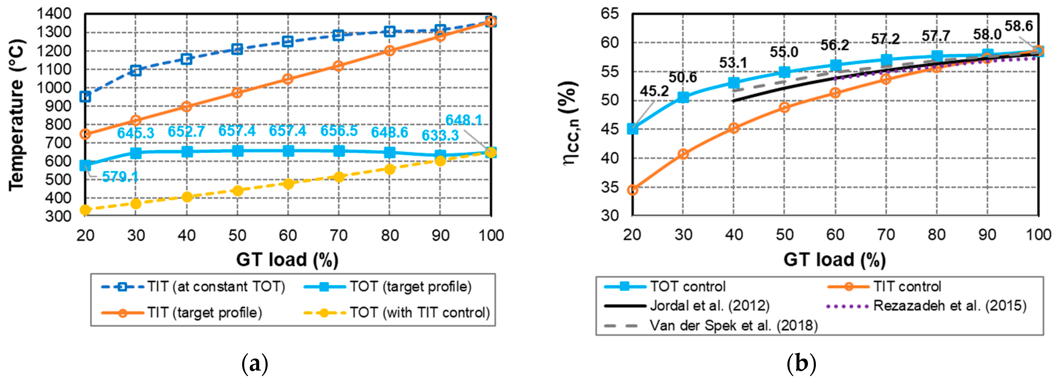
Figure 1. Part load behavior of the NGCC—3PRH configuration: (a) TOT vs. TIT control strategy; (b) CC net electric efficiency in comparison with published literature [22,23,24].
Energies 17 03501 g001
Figure 2. Part load behavior of the NGCC—3PRH configuration: (a) mass flow rate and temperature of the exhaust exiting the HRSG (labels indicate CO2 concentration (vol%); (b) inlet pressure at HP, IP, and LP turbine stages.
Energies 17 03501 g002
Figure 3. Part load behavior of the NGCC—2P configuration: (a) TOT control strategy; (b) CC net electric efficiency in comparison with published literature [34].
Energies 17 03501 g003
Figure 4. Part load behavior of the NGCC—2P configuration: (a) mass flow rate and temperature of the exhaust exiting the HRSG (labels indicate CO2 concentration (vol%); (b) inlet pressure at HP and LP turbine stage.
Energies 17 03501 g004
Figure 5. Part load behavior of the NGCC—1P configuration: (a) TOT control strategy; (b) CC net electric efficiency in comparison with published literature [36].
Energies 17 03501 g005
Figure 6. Part load behavior of the NGCC—1P configuration: (a) mass flow rate and temperature of the exhaust exiting the HRSG (labels indicate CO2 concentration (vol%); (b) inlet pressure at HP and LP turbine stage.
Energies 17 03501 g006
Figure 7. Simplified layout of the CO2 capture unit.
Energies 17 03501 g007
Figure 8. Process flow diagram of the CO2 capture process (dashed lines represent options not used in this study).
Energies 17 03501 g008
Figure 9. Non-dimensional SRD as a function of CO2 concentration in flue gas.
Energies 17 03501 g009
Figure 10. Sources of power loss due to carbon capture for 3PRH, 2P, and 1P NGCC layouts as a function of GT load: (a) PCC electrical consumption and ST nonproduction (percentage shares); (b) resulting ST contribution to CC gross power.
Energies 17 03501 g010
Figure 11. Performance of topping and bottoming cycles for 3PRH, 2P, and 1P NGCC layouts as a function of GT load: (a) GT gross efficiency; (b) Rankine cycle efficiency.
Energies 17 03501 g011
Figure 12. Characterization of LP steam for 3PRH, 2P, and 1P NGCC layouts as a function of GT load: (a) pressure at the inlet of LP ST (labels indicate the mass flow rate through it); (b) extracted flow rate for reboiler.
Energies 17 03501 g012
Figure 13. Characterization of PCC electrical consumption for 3PRH, 2P, and 1P NGCC layouts as a function of GT load: (a) total amount (labels indicate fraction to total auxiliaries); (b) main types (percentage shares).
Energies 17 03501 g013
Figure 14. (a) PCC thermal energy consumption in comparison with published literature [23,24,25] and (b) GT air–fuel ratio for 3PRH, 2P, and 1P NGCC layouts as a function of GT load.
Energies 17 03501 g014
Figure 15. Effects of PCC on NGCC performance for 3PRH, 2P, and 1P layouts as a function of GT load: (a) percentage reduction in net power; (b) net power with (and without) PCC.
Energies 17 03501 g015
Figure 16. Effects of PCC on NGCC performance for 3PRH, 2P, and 1P layouts as a function of GT load: (a) loss in net efficiency (pp) in comparison with published literature [22,24]; (b) net efficiency with (and without) PCC.
Energies 17 03501 g016
Figure 17. CO2 emission intensity for 3PRH, 2P and 1P NGCC layouts as a function of GT load.
Energies 17 03501 g017
Table 1. Natural gas properties.
Fuel Composition [vol%]
Methane (CH4)87
Ethane (C2H6)8.46
Nitrogen (N2)3.65
Hydrogen (H2)0.36
Carbon dioxide (CO2)0.34
Carbon monoxide (CO)0.09
Oxygen (O2)0.07
Ethylene (C2H4)0.03
Lower heating value [kJ/kg]46,280
Table 2. Design data of NGCC power island for the investigated configurations.
Nominal Parameters3PRH2P1P
GT inlet air (kg/s)501.2132.3407.7
Compressor pressure ratio182113.2
Turbine inlet temperature (°C)1357.21310.21179
GT exhaust mass flow (kg/s)514.2135.3416.1
GT exhaust temperature (°C)648.1569.5541
ST-HP conditions (bar/°C)181.2/566.150/52050/520
ST-IP conditions (bar/°C)42.6/566.1--
ST-LP conditions (bar/°C)4.4/280.86/2595/231
Condenser pressure (bar)0.0690.080.08
Table 3. Design data of CO2 capture unit for the investigated configurations.
Nominal Parameters (90% Capture Rate)3PRH2P1P
Rich solvent flow rate (kg/s)1226.5142.6396.3
Solvent consumption (kg/s)0.02450.002850.00793
Heating steam flow rate (kg/s)92.2510.8330.39
Heating steam quality * (bar/°C)4.4/2834.4/2275/231
CO2 captured (kg/s)61.337.1319.82
SRD (MJ/kg CO2)3.2793.3123.342
Condensate return ** (bar/°C)1.9/1182.4/126.62.4/126.6
* At the point of extraction from the LP turbine (component number: 80/81 in Figure A2; 17 in Figure A3 and Figure A4). ** At the entry point into the HRSG.
Table 4. NGCC net power with and without PCC for the investigated configurations, as a function of GT load.
GT Load (%)3PRH2P1P
w/o PCC
(MW)
with PCC
(MW)
∆ (%)w/o PCC
(MW)
with PCC
(MW)
∆ (%)w/o PCC
(MW)
with PCC
(MW)
∆ (%)
20195.5165.415.420.316.718.2---
30272.1235.813.428.624.215.3---
40338.7296.012.636.131.014.3---
50403.9354.412.343.037.113.7115.598.414.9
60467.2410.712.149.743.113.2132.9113.914.4
70529.4465.612.056.349.013.0149.3128.414.1
80588.4517.012.162.254.112.9165.4142.414.0
90643.5563.812.467.959.212.9181.0156.113.9
100708.9621.612.374.565.012.8196.2169.213.8
Table 5. NGCC net electric efficiency with and without PCC for the investigated configurations. as a function of GT load.
GT Load (%)3PRH2P1P
w/o PCC
(%)
with PCC
(%)

(pp)
w/o PCC
(%)
with PCC
(%)

(pp)
w/o PCC
(%)
with PCC
(%)

(pp)
2045.2238.256.9736.8530.146.71---
3050.5743.826.7542.3535.896.46---
4053.1346.446.6945.6539.136.52---
5054.9548.226.7347.6741.156.5245.7138.916.8
6056.2249.436.7949.2642.746.5247.140.316.79
7057.1650.36.8650.5243.976.5548.1541.346.81
8057.7450.756.9951.4344.796.6449.0242.176.85
9057.9850.817.1752.2145.486.7349.7542.846.91
10058.6351.427.2153.0846.36.7850.3643.396.97
Table 6. CO2 emission intensity with and without PCC for the investigated NGCC configurations. as a function of GT load.
GT Load (%)3PRH2P1P
w/o PCCwith PCCw/o PCCwith PCCw/o PCCwith PCC
kg CO2/MWhn
20450.153.2553.367.6--
30401.846.4480.356.7--
40382.343.7445.251.9--
50369.542.1426.349.4444.852.2
60361.041.1412.447.5431.650.4
70355.040.4402.046.2422.149.2
80351.540.0394.945.3414.648.2
90350.039.9389.144.7408.647.4
100346.139.5382.643.9403.646.8
Disclaimer/Publisher’s Note: The statements, opinions and data contained in all publications are solely those of the individual author(s) and contributor(s) and not of MDPI and/or the editor(s). MDPI and/or the editor(s) disclaim responsibility for any injury to people or property resulting from any ideas, methods, instructions or products referred to in the content.