Article

Five-Stage Fast Charging of Lithium-Ion Batteries Based on Lamb Waves Depolarization

by
Tong Wang
and
Wei Liang
*
School of Mechanical and Automotive Engineering, Shanghai University of Engineering Science, Shanghai 201620, China
*
Author to whom correspondence should be addressed.
Energies 2024, 17(12), 2992; https://doi.org/10.3390/en17122992
Submission received: 23 May 2024 / Revised: 11 June 2024 / Accepted: 14 June 2024 / Published: 18 June 2024
(This article belongs to the Section D2: Electrochem: Batteries, Fuel Cells, Capacitors)

Abstract

:
Lithium-ion batteries are essential for the development of consumer electronics and electric vehicles due to their high energy density, low self-discharge rate, and easy maintenance. To optimize the performance of lithium-ion batteries and meet the battery requirements of devices, it is necessary to charge the batteries at a faster rate. Therefore, this paper proposes a five-stage constant current charging method based on Lamb wave depolarization to enhance the charging efficiency. Specifically, the orthogonal experimental method is first used to determine the near-optimal value of the charging current in each stage of the five-stage constant current charging process. Subsequently, Lamb waves are introduced during the charging process of each constant current charging stage. Compared with the traditional five-stage constant current charging method, the five-stage constant current charging method based on Lamb wave depolarization improves the charging efficiency. The charging efficiency of the five-stage constant current charging method based on Lamb wave depolarization with an excitation voltage peak-to-peak amplitude Vpp of 120 and an excitation duration of 6 min is 20% higher than that of the traditional five-stage constant current charging method. The weakening of the polarization effect is positively correlated with the Lamb wave excitation voltage. In addition, the five-stage constant current charging method based on Lamb wave depolarization is superior to the five-stage constant current shelving depolarization charging method and the five-stage constant current negative pulse depolarization charging method in improving the charging efficiency.

1. Introduction

Lithium-ion batteries have become the most popular energy storage solution in modern society due to their high energy density, low self-discharge rate, long cycle life, and high charge/discharge multiplier [1,2,3]. Electric vehicles have a significant impact on the environment and people’s behavior, contributing to the advancement of sustainable transportation [4,5]. Lithium-ion batteries are one of the most commonly used energy storage devices in electric vehicles. In order to accelerate the popularity of electric vehicles and maximize the performance of lithium-ion batteries, optimizing the charging speed of lithium-ion batteries is essential. Standard charging strategies for lithium-ion batteries include the constant current charging method and the constant current constant voltage charging method [6]. However, the constant current constant voltage charging method is unsuitable for fast charging because the constant voltage charging stage significantly prolongs the charging time and reduces the battery’s cycle life [7,8,9]. A significant amount of literature has been published on investigating charging strategies for lithium-ion batteries to reduce charging time. One such method is the multi-stage constant current charging method, known for its high charging/discharging energy efficiency and long cycle life [10,11,12,13]. Zhang proposed a multi-stage charging method and found that it can improve the charging efficiency of batteries [14]. Ref. [15] reports that an integer linear programming algorithm was utilized to determine that there is no significant enhancement in charging efficiency when the number of multi-stage charging segments exceeds 5. Hsieh et al. utilized the Taguchi experimental design method to identify the optimal combination of charging currents for the five-stage constant current charging method [16]. The lithium battery was then charged using the acquired combination. Compared to the traditional charging method, this approach enhances the battery’s cycle life and reduces charging time. The charging efficiency, time, and cycle life of the battery are significantly affected by the polarization effect during the charging process, even though the five-stage constant current charging method greatly increases the speed of lithium-ion battery charging [17]. Therefore, optimizing the polarization voltage has become a prominent issue to address, considering the presence of the polarization phenomenon and its impact on the battery’s charging capacity. In Ref. [18], a pulse charging method was employed to alleviate the polarization effect, and the impact of pulse charging frequency on this phenomenon was investigated. Lu et al. proposed an intermittent alternating current charging method based on the optimal current charging curve [19]. They added shelving to the charging process to alleviate the polarization phenomenon. However, the use of the depolarization method reduces the charging efficiency of lithium-ion batteries. Negative pulse depolarization presents some issues, such as complex implementation and high operating costs. Therefore, researchers aim to identify a depolarization method that is low-cost, easy to implement, and does not affect charging efficiency.
Ultrasonic waves have been utilized to induce acoustic streaming-driven fluid stirring and enhance the uniformity of ion distribution in traditional chemical vapor deposition processes [20]. Surface acoustic wave devices offer exceptional power density in fingernail-sized devices and can be utilized for droplet processing, cell manipulation, and particle collection in microfluidics [21,22]. Lamb waves are elastic waves that propagate in solid sheets or thin film materials, and their propagation characteristics depend on the relationship between the thickness of the sheet and the wavelength [23]. Lamb waves include symmetric and antisymmetric modes and propagate throughout the thickness of the sheet. When Lamb waves propagate to the boundary between solid and liquid, leakage acoustic Lamb waves are generated [24]. The acoustic energy generated by this leakage acoustic Lamb wave propagates into the liquid in the form of longitudinal waves and decays within a certain distance, thereby creating an effective body force in the liquid [25]. The generated body force can induce significant acoustic streaming in the liquid, enhancing liquid mixing, stirring, vibration, pumping, spraying, and atomization [26]. When the acoustic energy generated by the leaking Lamb wave propagates into the electrolyte in the form of longitudinal waves, it can induce an acoustic field effect in the electrolyte. This acoustic field effect can influence the movement of ions in the electrolyte. During the charging process of lithium-ion batteries, lithium ions diffuse from the positive electrode to the negative electrode. As the charging process progresses, the concentration of lithium ions inside the battery becomes unbalanced [20], creating a concentration gradient between the two electrodes [27]. This gradient may cause a potential deviation from the equilibrium between the two electrodes. The acoustic streaming force generated by the propagation of Lamb waves into the electrolyte accelerates the mass transfer of lithium ions, disrupts the concentration gradient between the electrodes, homogenizes the concentration of lithium ions in the electrolyte, and mitigates the polarization effect. Therefore, an increasing number of researchers are exploring the potential of utilizing Lamb waves in the field of electrochemistry. Tietze et al. utilized Lamb waves to disrupt the boundary layer near the anode of a lithium battery in order to improve the mass transfer of ions, consequently achieving acoustically enhanced current [28]. Ref. [20] reported that in an experiment using Lamb waves to drive the flow of electrolytes, it was found that surface acoustic waves reduced the polarization effect in lithium metal batteries.
In this paper, a five-stage constant current charging method based on Lamb wave depolarization is proposed to enhance the charging efficiency. Compared to the traditional five-stage constant current charging method, the five-stage constant current charging method based on Lamb wave depolarization shortens the charging time and enhances the charging efficiency. In addition, the study analyzes the impact of two variables, Lamb wave excitation duration and excitation voltage, on the five-stage constant current charging method based on Lamb wave depolarization. The rest of this paper is organized as follows: Section 2 introduces the research methods. The orthogonal experimental method is utilized to determine the near-optimal charging current value for the five-stage constant current charging process. The polarization voltage is explained using the second-order RC equivalent circuit model of the battery. Section 3 outlines the experimental equipment and procedures. Section 4 compares and analyzes the experimental results. Section 5 summarizes the entire paper.

2. Research Methodology

2.1. Determination of Parameters for Five-Stage Fast Charging

This article determines the current values of each stage in the five-stage constant current charging method through charge and discharge experiments. The orthogonal experimental method is utilized to minimize the number of experiments and promptly identify the optimal current value and combination at each stage.
The steps of the orthogonal experimental method are as follows:
Step 1: Identify the experimental subjects. This article utilizes the LIR1220 rechargeable lithium-ion battery manufactured by Shenzhen Xinlego Electronic Technology Co., Ltd. in Shenzhen, China, and its parameters are presented in Table 1. The charge and discharge current of the battery is expressed by the corresponding charge and discharge multiple C. The charging current is 1 C, indicating that the battery is charged with a current of 10 mA.
Step 2: Determine experimental parameters. In each charging stage of the five-stage constant current charging method, 10 alternative values for the charging current were set, with a difference of 0.05 C between each two alternative values. Table 2 displays the alternative charging current values for each charging stage. Furthermore, the last five alternating current values in each charging stage were used as the first five alternating current values in the following charging stage.
Step 3: Select the appropriate orthogonal table. The orthogonal table is a collection of standard design tables denoted by Ln(mk). This notation signifies that each row of the table contains k factors, with n rows in total, and each factor has m levels. The number of rows, n, can be determined using the formula n = k · (m − 1) + 1. The experiment described in this paper aims to determine the specific current value for each stage of a five-stage constant current charging process. Three alternative values are set for each iteration. Therefore, a hybrid orthogonal table L18(21 × 37) is selected for this study. Removing the number of orthogonal table columns according to the number of factors does not affect the experimental results. Thus, by removing the first column of L18(21 × 37) and any two other columns, we can obtain the orthogonal table L18(35) needed for the experiments designed in this paper, as illustrated in Table 3. The three levels 1, 2, and 3 of the orthogonal table indicate the three alternative values of high, medium, and low charging currents, respectively.
The difference between the values of each level is set to 0.1 C according to the orthogonal table above. The alternative values for the three levels of current values at each stage are shown in Table 4, where I1, I2, I3, I4, and I5 represent the first through fifth stages of the charging process, respectively.
Step 4: Settings for charge and discharge experiments. The five-stage constant current charging experiment is conducted by utilizing different charging current values as specified in the orthogonal table. When the charging process reaches the cut-off voltage of 4.2 V, proceed to the next stage of charging. Allow the battery to stand for 10 min after charging, and then discharge it at a constant current of 0.5 C. Discharge ends when the battery voltage reaches 2.75 V, which is the discharge cut-off voltage. Record the charging efficiency value of the lithium-ion battery, which is calculated as the ratio of the battery’s charging capacity to the charging time. Determine the optimal combination of charging current values for this iteration based on the charging efficiency value.
Step 5: The iterations converge. The following rules are used to calculate the level value of the factor in the next iteration [17]: If the best value of the alternative charging current is the maximum or middle value, the horizontal position remains unchanged, and the level difference is reduced to 0.05 C. If the best value is the minimum, the horizontal position is moved to the middle, and the level difference remains at 0.1 C. When the level difference of each factor reaches 0.05 C, the iteration meets the convergence condition, the experiment is terminated, and the results are presented in Table 5. The final charging current values for the five-stage constant current charging process are 2.0 C, 1.65 C, 1.45 C, 1.2 C, and 0.7 C for the first to fifth stages, respectively.

2.2. Description of Polarization Voltage

Figure 1 illustrates the second-order RC equivalent circuit model of the battery. This model is used to connect the internal chemical reactions and external output characteristics of the battery. In Figure 1, V0 represents the battery terminal voltage, I stands for the charging current, RΩ represents the internal connection impedance of the battery, and open circuit voltage (OCV) denotes the battery electric potential. Rp1 represents the charge transfer impedance, Cp1 stands for the polarization capacitance, Rp2 denotes the diffusion resistance, Cp2 indicates the charge corresponding to the concentration difference diffusion, and Vp represents the polarization voltage.

3. Experiment

3.1. Experimental Device

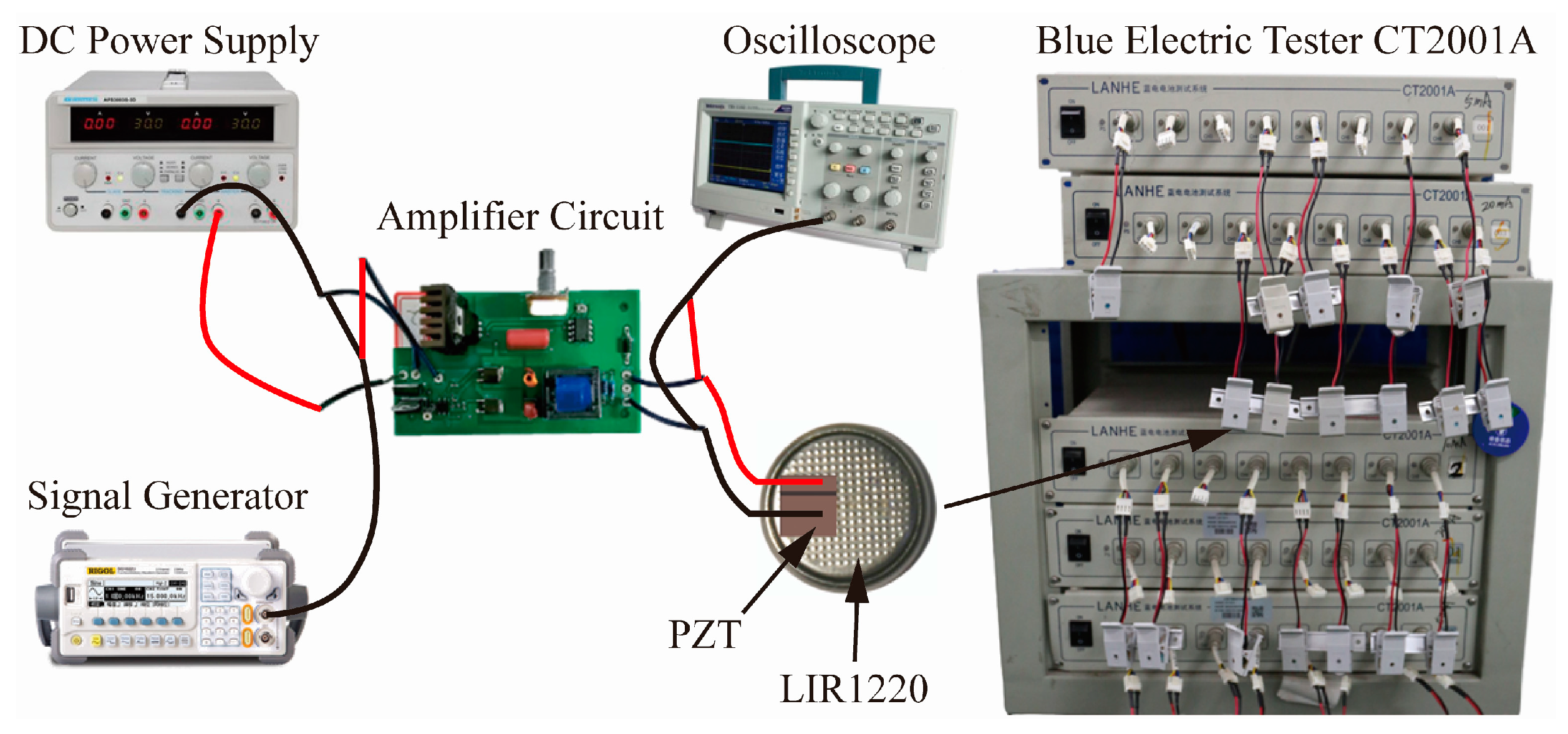
The experimental setup is shown in Figure 2. The charging and discharging instrument used in this paper is the CT2001A battery tester produced by Wuhan Lander Electronics Co., Ltd. in Wuhan, China. It has a current range of 100 mA, a voltage range of 5 V, and 8 channels. The piezoelectric ceramic (PZT) is bonded to the rechargeable lithium-ion battery LIR1220 using epoxy resin adhesive. The PZT model used in the experiment is PIC255, produced by PI Ceramics in California, USA, with dimensions of 6 mm × 4 mm × 1 mm. A DC power supply (ATTEN APS3005S-3D1 model, manufactured by Shenzhen AT-TEN Technology Co., Ltd., Shenzhen, China), a signal generator (RIGOL DG1022U model, manufactured by RIGOL Technology Co. Ltd., Suzhou, China), and a homemade amplifier circuit are utilized to produce an alternating voltage and apply it to the PZT, inducing Lamb waves in the battery bonded to the PZT. An oscilloscope (Tektronix TDS2012C model, manufactured by Tektronix Technology (China) Co., Ltd., Shanghai, China) is used to detect the waveform of the alternating voltage.

3.2. Experimental Procedure

3.2.1. Traditional Five-Stage Constant Current Charging Method Experiment

The rechargeable lithium-ion battery LIR1220 is charged using the traditional five-stage constant current charging method with the blue battery tester CT2001A, as depicted in Figure 2. The charging currents of each constant current charging stage are 2.0 C, 1.65 C, 1.45 C, 1.2 C, and 0.7 C, respectively. When the charging voltage reaches the charging cut-off voltage of 4.2 V, it switches to the next stage of constant current charging. When the charging voltage in the final charging stage reaches 4.2 V, the experiment concludes with a constant current discharge of 0.5 C to the discharge cut-off voltage of 2.75 V. The experiment is repeated 10 times. The charging experiment was set as the control group.

3.2.2. Experiment on Five-Stage Constant Current Charging Method with Lamb Wave Effect

A five-stage constant current charging experiment with Lamb wave effect was conducted on the same batch of rechargeable lithium-ion batteries LIR1220 using the blue battery tester CT2001A. Before the experiment, the PZT was bonded to the battery using epoxy resin glue. The charging current setting for the five-stage constant current charging experiment with Lamb wave effect is the same as that of the traditional five-stage constant current charging experiment. In contrast to the traditional five-stage constant current charging experiment, the five-stage constant current charging experiment with Lamb wave effect generates Lamb waves that impact the battery by activating the PZT attached to the battery during the localized charging process. The excitation voltage and excitation duration of the Lamb wave are used as experimental variables to analyze the impact of Lamb waves excited at different excitation voltages and durations on five-stage constant current charging.
First, experiments were conducted with the Lamb wave excitation duration as a variable. Lamb waves were excited at a frequency of 1 MHz. The peak-to-peak amplitude Vpp of the Lamb wave excitation voltage is fixed at 80. The Lamb wave is excited after 2 min of charging in the first stage of a five-stage constant current charging process. The Lamb wave continues to propagate for 4 min and then ceases. At the beginning of each subsequent constant current charging stage, the Lamb wave is excited and continues to propagate for 2 min. When the charging voltage of the final charging stage reaches 4.2 V, the experiment concludes with a constant current discharge of 0.5 C to the discharge cut-off voltage of 2.75 V. The excitation duration of the Lamb wave, which was initiated two minutes after the beginning of charging in the initial constant current charging stage, was altered to 5 min, 6 min, 7 min, and 8 min. During the next four constant current charging stages, the Lamb wave that was excited at the beginning of charging remains unchanged for 2 min. Experiments were conducted according to the above settings to study the effect of Lamb wave excitation duration on battery charging.
Subsequently, the timing and duration of adding Lamb waves in each constant current charging stage during the five-stage constant current charging process were kept unchanged. The experiment was then conducted with the excitation voltage of the Lamb wave as a variable. The peak-to-peak amplitude Vpp of the Lamb wave excitation voltage was set to 80, 100, and 120, respectively, to conduct a five-stage constant current charging experiment with Lamb wave effect. In order to obtain more accurate results, each experiment was performed 10 times, and then the average value was calculated.

4. Results and Discussion

4.1. Relationship between Charging Efficiency and Excitation Time

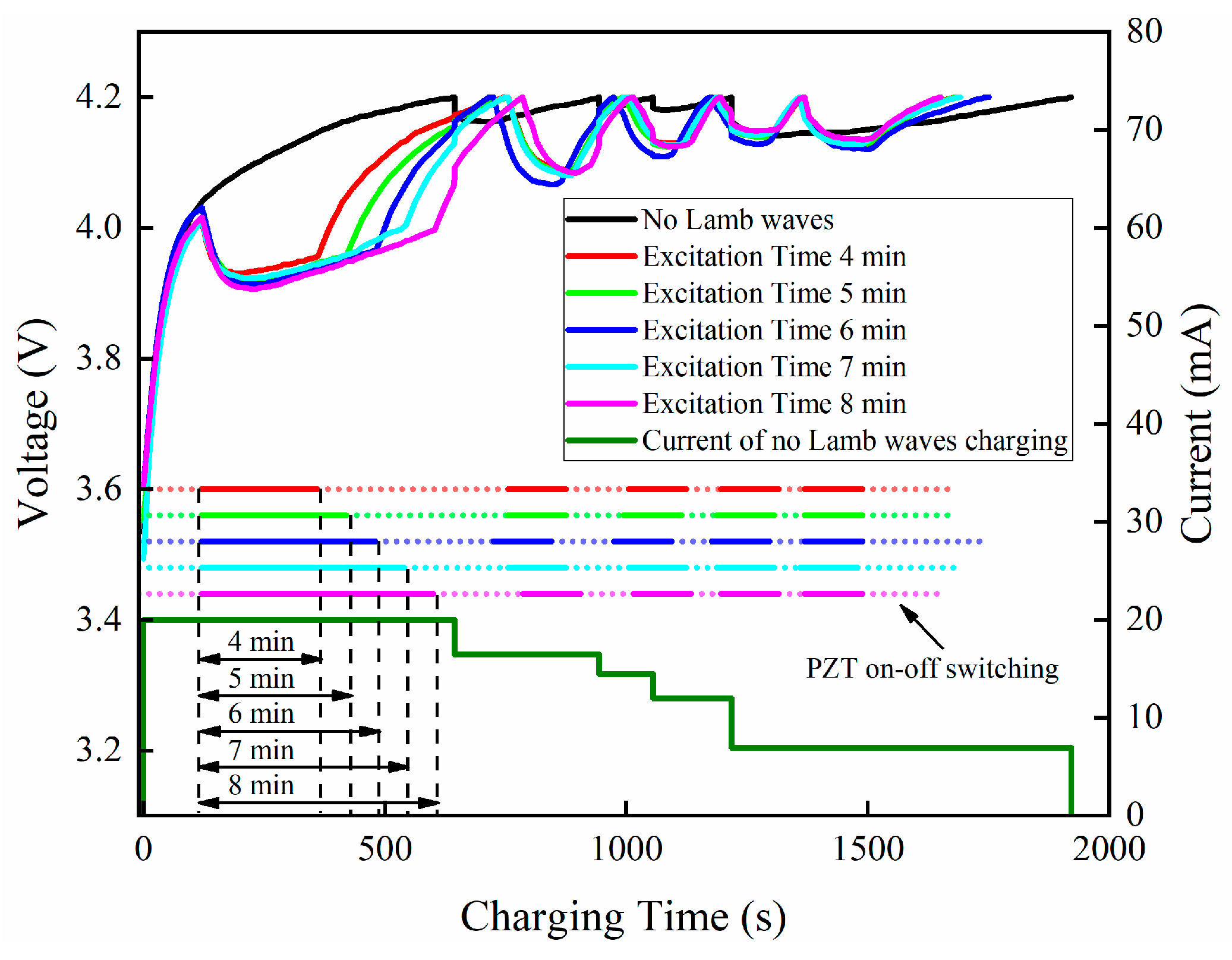
The peak-to-peak amplitude Vpp of the Lamb wave excitation voltage is set to 80 and remains unchanged. The Lamb wave excitation durations after two minutes of charging in the first constant current charging stage are 4 min, 5 min, 6 min, 7 min, and 8 min, respectively. The dot-dashed line in Figure 3 represents the PZT on-off switching, while the length of the solid line portion indicates the duration of Lamb wave excitation. It can be seen from Figure 3 that after the Lamb wave is excited, the battery terminal voltage drops significantly. This is due to the accelerated mass transfer of lithium ions in lithium-ion batteries [29], which decreases the concentration gradient of lithium ions in the electrolyte [20] and alleviates the polarization effect of the battery [30]. Additionally, the polarization voltage decreases. When the battery terminal voltage drops to a certain value, it stabilizes. The duration of the Lamb wave stimulation affects the stability of the voltage over time. Once the Lamb wave stops, the battery terminal voltage gradually rises. In the later stages of charging, the polarization effect causes the battery voltage to rise sharply, leading to incomplete battery charging [31,32]. It can be clearly seen from Figure 4 that the charging capacity of the five-stage constant current charging with Lamb wave effect is greater than the five-stage constant current charging without Lamb wave effect. The Lamb waves reduce the polarization effect and enhance the charging capacity of the battery.
It can be seen from Figure 5 that the charging time of a five-stage constant current charging process with Lamb wave effect is shorter than that of a five-stage constant current charging process without Lamb wave effect. The charging time of the five-stage constant current charging method with Lamb wave excitation duration of 6 min is 1751 s, which is 8.4% faster than the charging time of 1921 s of the five-stage constant current charging without Lamb wave effect. The duration of Lamb wave excitation does not show any obvious relationship with the charging time.
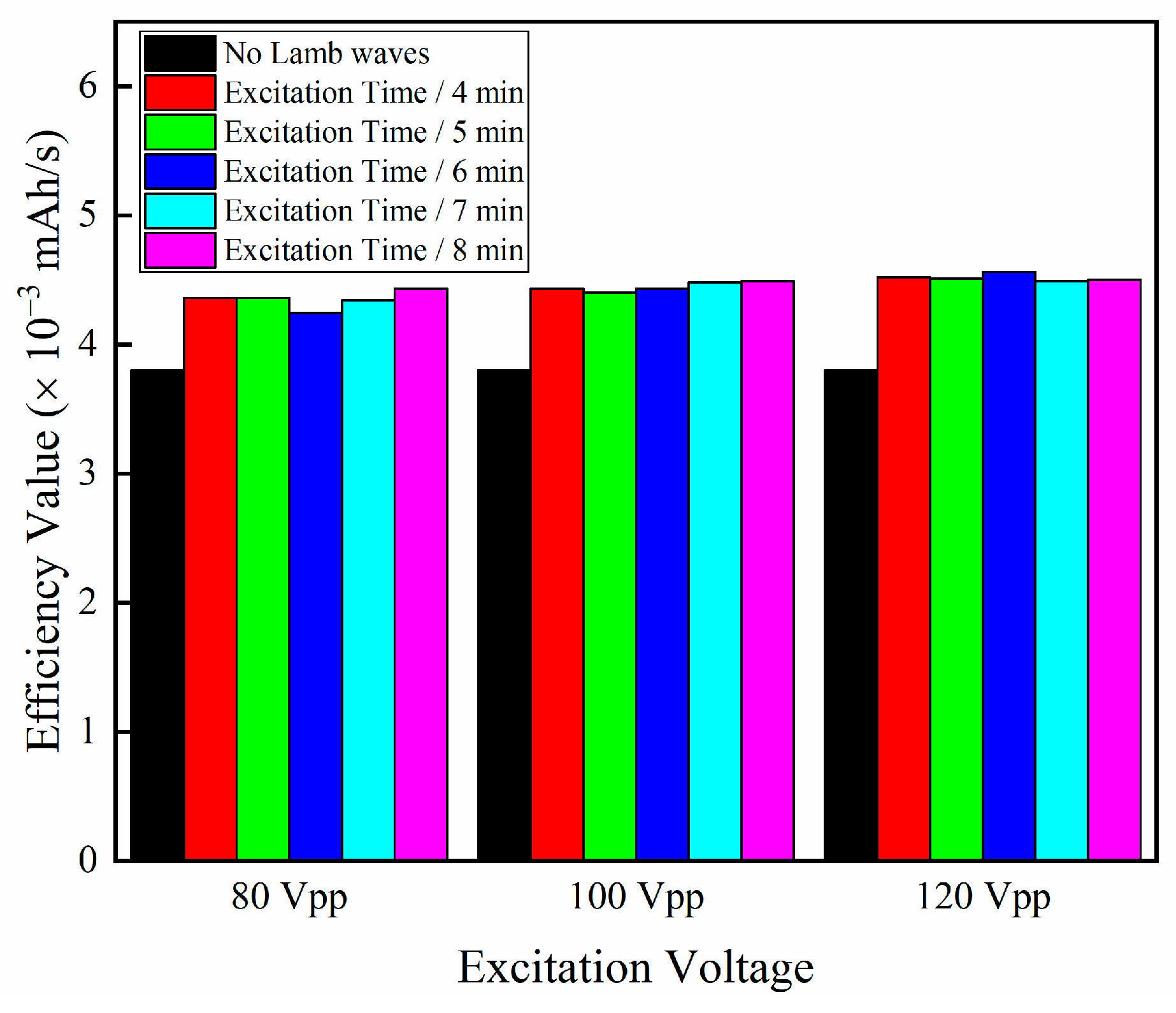
Figure 6 displays the charging efficiency values of the five-stage constant current charging method under various Lamb wave excitation durations. The charging efficiency value of the five-stage constant current charging without Lamb wave effect is 3.8 × 10⁻³ mAh/s. When the Lamb wave excitation voltage peak-to-peak amplitude Vpp is 80 and the excitation duration is 4 min, the charging efficiency value is 4.36 × 10⁻³ mAh/s, which is 14.74% higher than the five-stage constant current charging without the Lamb wave effect. When the Lamb wave excitation lasts for 8 min, the charging efficiency value is 4.43 × 10⁻³ mAh/s, which is 16.58% higher than the five-stage constant current charging without Lamb wave effect. When the Lamb wave excitation voltage is constant, the charging efficiency of the five-stage constant current charging method with Lamb wave action is improved under different Lamb wave excitation durations compared to the traditional five-stage constant current charging method. However, increasing the duration of Lamb wave excitation has little effect on the charging efficiency value.

4.2. Relationship between Charging Efficiency and Excitation Voltage

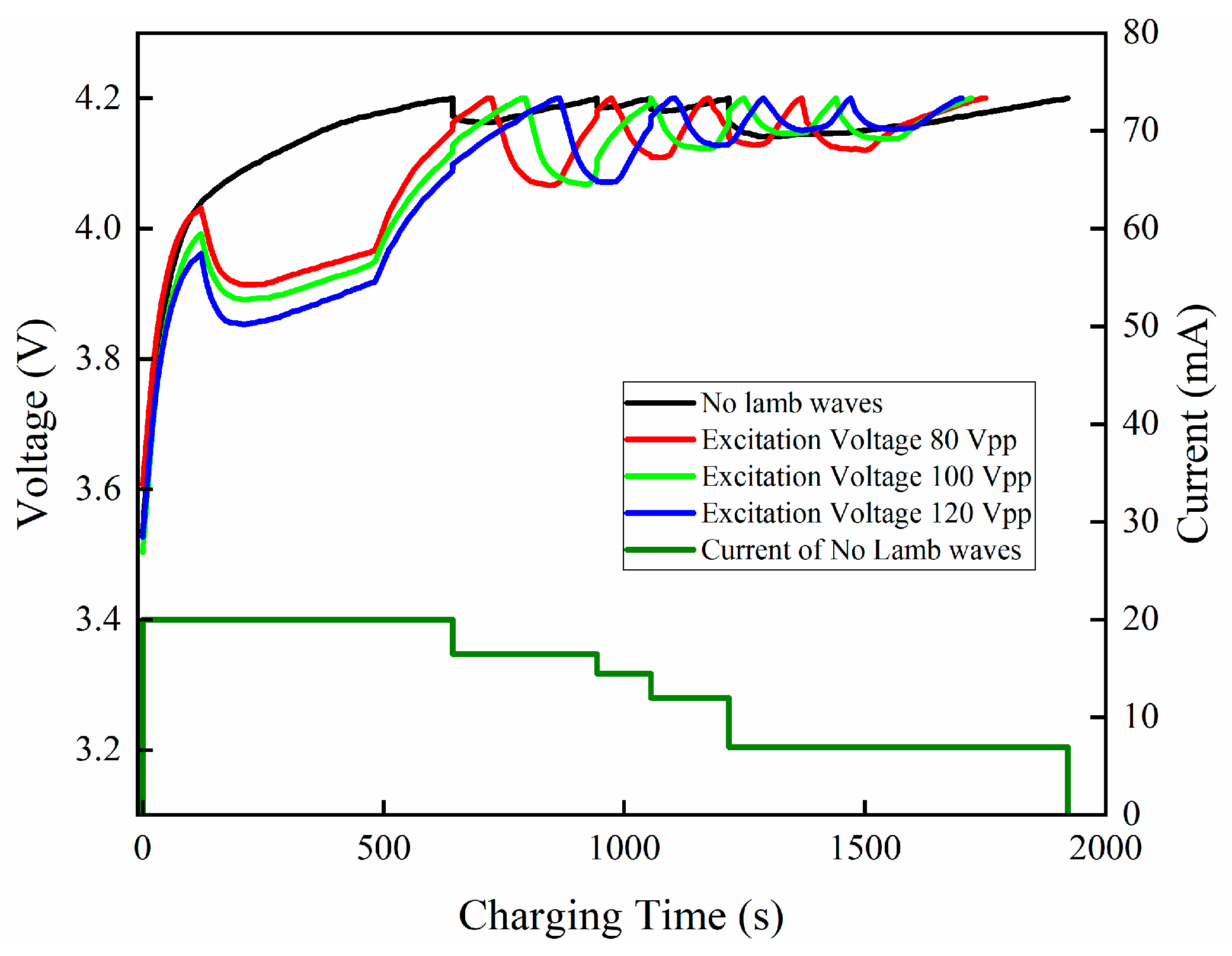
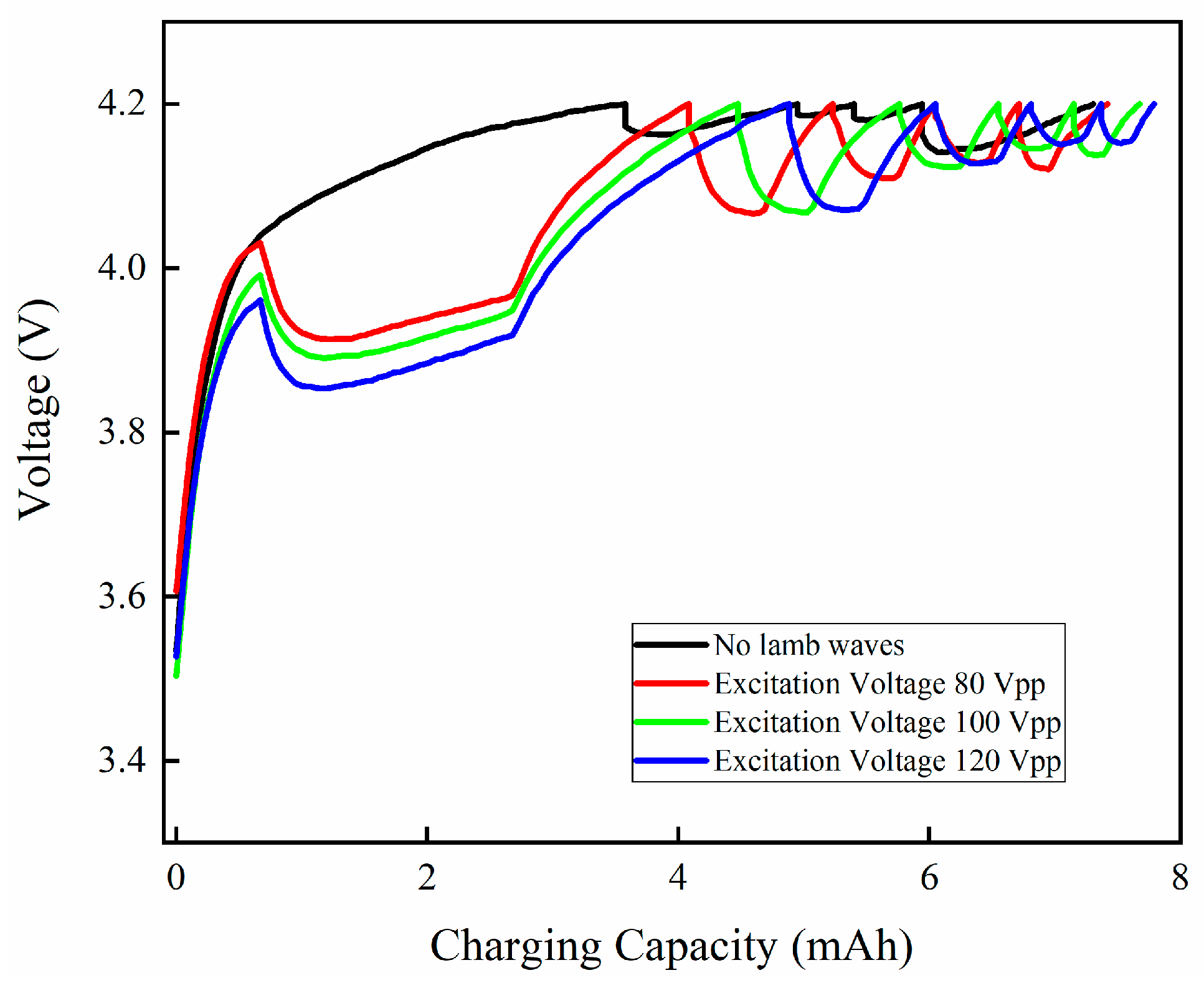
Figure 7 illustrates the influence of various excitation voltages on the five-stage constant current charging when the Lamb wave excitation duration is fixed at 6 min and added to the first constant current charging stage. It can be seen from the figure that when Lamb waves are excited at different excitation voltages, the terminal voltage of the battery starts to decrease significantly compared to the five-stage constant current charging without Lamb wave effect. Furthermore, the decrease in the battery terminal voltage is positively associated with the peak-to-peak value of the Lamb wave excitation voltage. The greater the peak-to-peak value of the excitation voltage that excites the Lamb wave, the greater the drop in the battery terminal voltage. This shows that the reduction of the polarization effect is positively related to the peak-to-peak value of Lamb wave excitation voltage. The greater the peak-to-peak value of Lamb wave excitation voltage, the more pronounced the depolarization effect becomes.
As shown in Figure 8, the charging capacity of the five-stage constant current charging with Lamb wave effect, when the peak-to-peak amplitude Vpp of the Lamb wave excitation voltage is 120, is significantly greater than that of the five-stage constant current charging without Lamb wave effect. The charging capacity remains almost the same when the Lamb wave excitation voltage peak-to-peak amplitude Vpp is 80 and 100 compared to the five-stage constant current charging without the Lamb wave effect. The larger the Lamb wave excitation voltage, the more effective it is in reducing the polarization effect. Figure 9 illustrates the total duration of five stages of constant current charging under various Lamb wave excitation voltages. It is evident from the figure that the total charging time of the five-stage constant current charging with Lamb wave effect is significantly shorter than the five-stage constant current charging without Lamb wave effect. The five-stage constant current charging method with Lamb wave excitation voltage peak-to-peak amplitude Vpp of 120 has a total charging time that is 11.14% shorter and a capacity that is 6.61% higher than the five-stage constant current charging method without the Lamb wave effect. As the Lamb wave excitation voltage increases, the charging time gradually shortens.
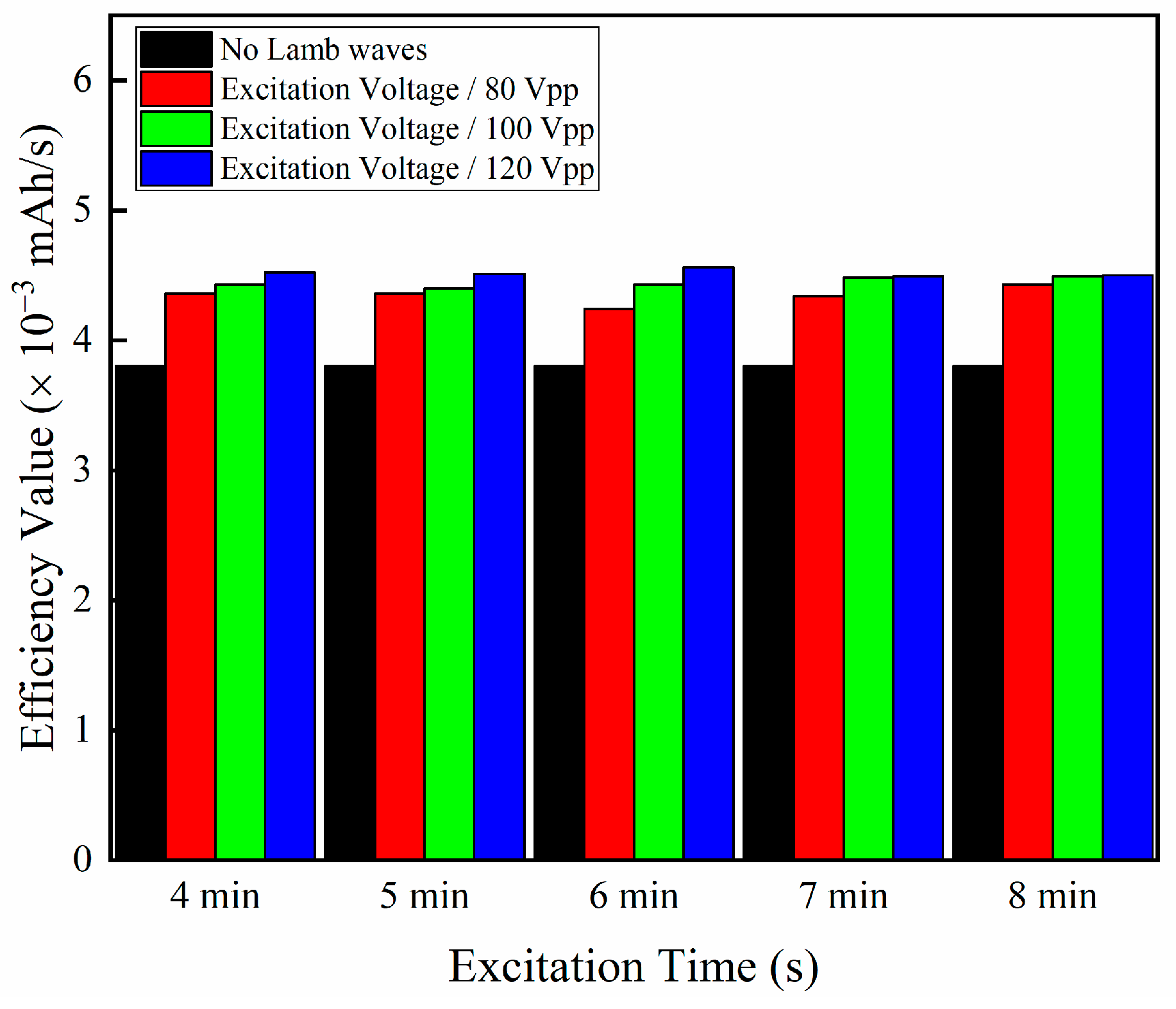
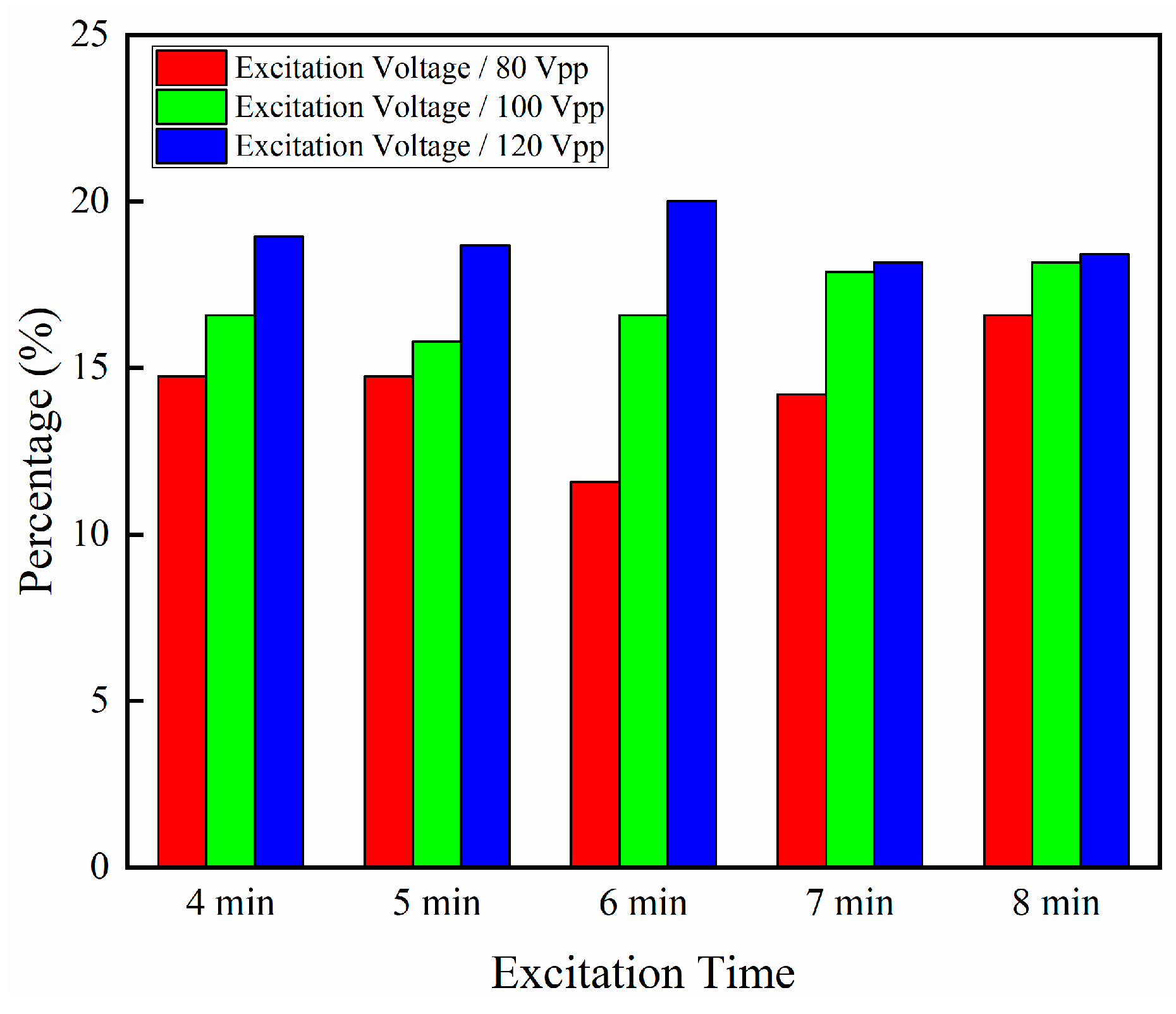
The results of the charging efficiency values from the five-stage constant current charging with Lamb wave effect, and the percentage increase in the charging efficiency value compared to the five-stage constant current charging without Lamb wave effect are depicted in Figure 10 and Figure 11. When the duration of Lamb wave excitation remains unchanged, the charging efficiency value is positively correlated with the Lamb wave excitation voltage. As the Lamb wave excitation voltage gradually increases, the charging efficiency value also increases gradually. The charging efficiency value of a five-stage constant current charging without the Lamb wave effect is 3.8 × 10⁻³ mAh/s. When the Lamb wave excitation duration is fixed at 6 min, the charging efficiency of a five-stage constant current charging with Lamb wave excitation voltage peak-to-peak amplitude Vpp of 80 is 4.24 × 10⁻³ mAh/s. This efficiency is 11.58% higher than that of five-stage constant current charging without the Lamb wave effect. The charging efficiency when the Lamb wave excitation voltage peak-to-peak amplitude Vpp is 80 and 100 is 4.43 × 10⁻³ mAh/s and 4.56 × 10⁻³ mAh/s, respectively. Compared with the five-stage constant current charging without Lamb wave effect, the charging efficiency increased by 16.58% and 20%, indicating a significant optimization effect.

4.3. Relationship between Lamb Wave Depolarization and Excitation Voltage

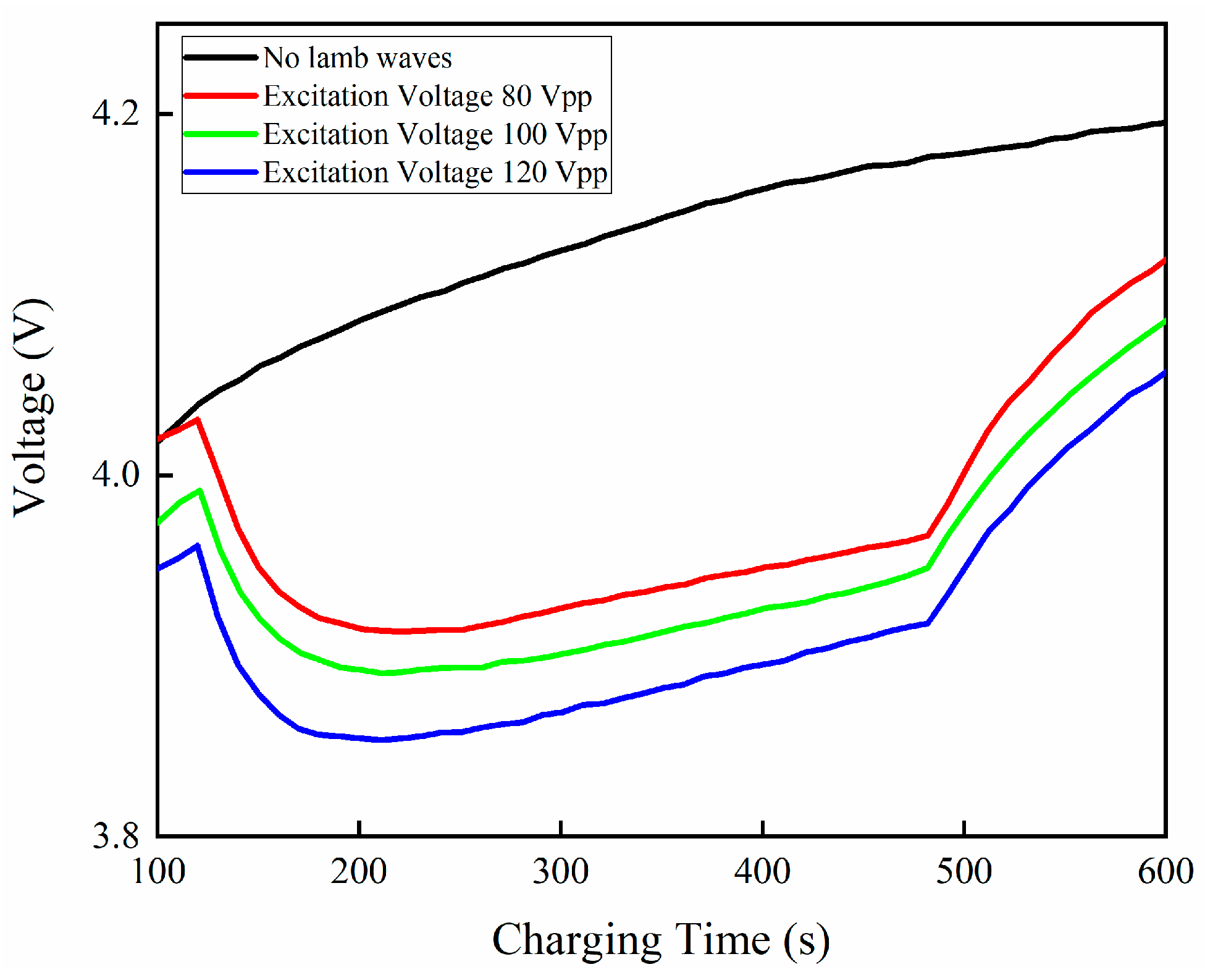
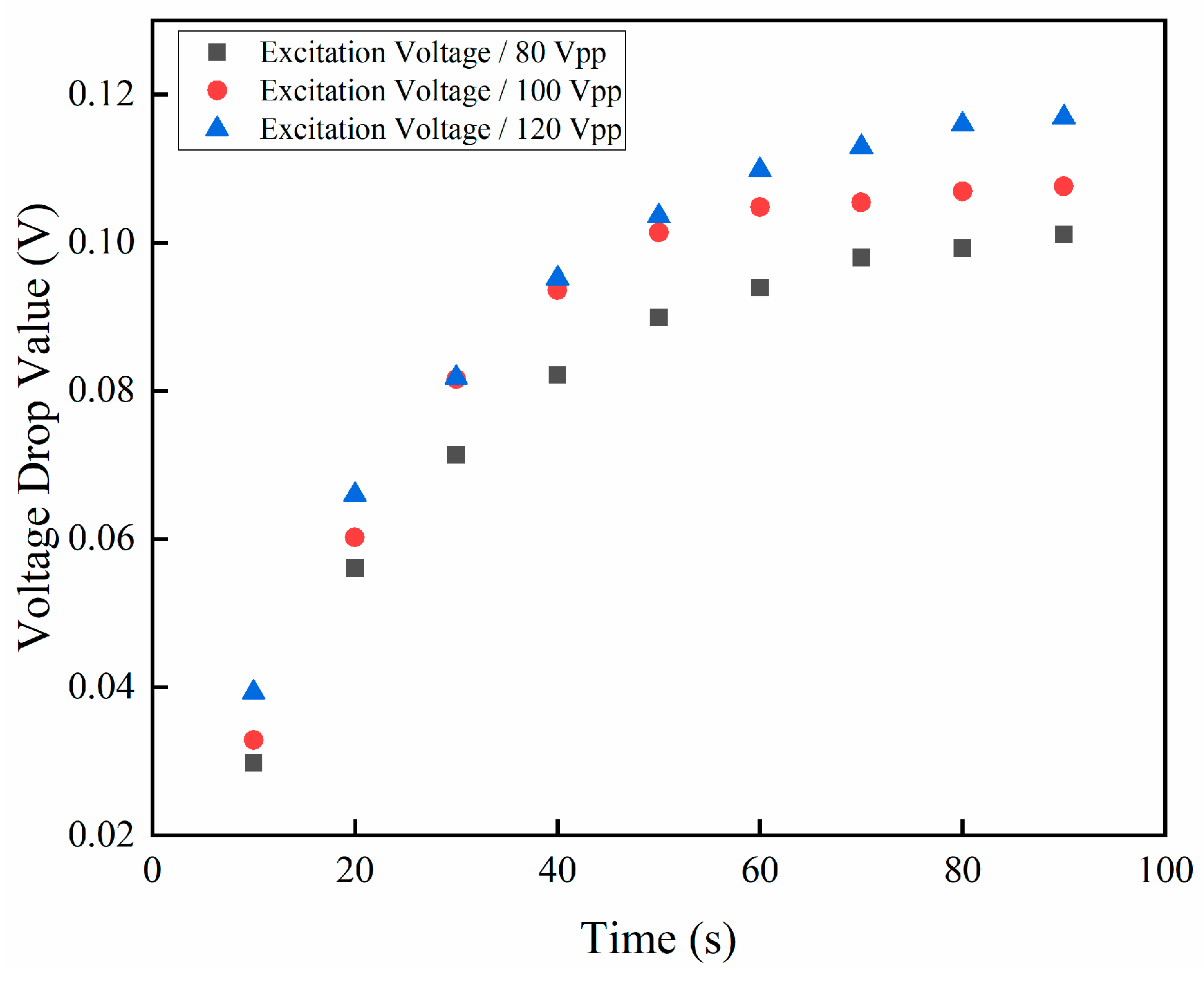
Figure 12 displays the battery terminal voltage under various Lamb wave excitation voltages. It can be seen from the figure that when the Lamb wave effect is added during the charging process, the battery terminal voltage drops rapidly. Moreover, the greater the peak value of the Lamb wave excitation voltage, the faster the battery terminal voltage drops. When the peak-to-peak amplitude Vpp of the Lamb wave excitation voltage is 80, 100, and 120, the battery terminal voltage drops by 0.0298 V, 0.0329 V, and 0.0393 V, respectively, within 10 s. As the charging process progresses, the battery terminal voltage of the five-stage constant current charging with Lamb wave effect gradually decreases. In the five-stage constant current charging without Lamb wave effect, the terminal voltage gradually increases during the charging process. Figure 13 depicts the curve of the voltage drop at the battery terminal during the five-stage constant current charging process with Lamb wave excitation voltage peak-to-peak amplitude Vpp is 80, 100, and 120, respectively. As shown in the figure, the voltage drop at the battery terminal gradually increases over time. Under the influence of various Lamb wave excitation voltages, the battery terminal voltage decreases by varying amounts. The greater the peak-to-peak amplitude of the Lamb wave excitation voltage, the greater the drop in the battery terminal voltage. According to the polarization voltage calculation method, the decrease in terminal voltage corresponds to the decrease in polarization voltage.
Table 6 displays the specific values of the battery terminal voltage decrease over time under various Lamb wave excitation voltage peak-to-peak values. At 90 s, the battery terminal voltage drop is 0.1169 V in the charging mode with the Lamb wave excitation voltage peak-to-peak amplitude Vpp of 120, which is 15.63% higher than the battery terminal voltage of 0.1011 V in the charging mode with the Lamb wave excitation voltage peak-to-peak amplitude Vpp of 80. Therefore, the greater the peak value of the Lamb wave excitation voltage and the greater the reduction in polarization voltage, the better the depolarization effect of the Lamb wave.

4.4. Comparison with Traditional Five-Stage Constant Current Depolarization Charging Method

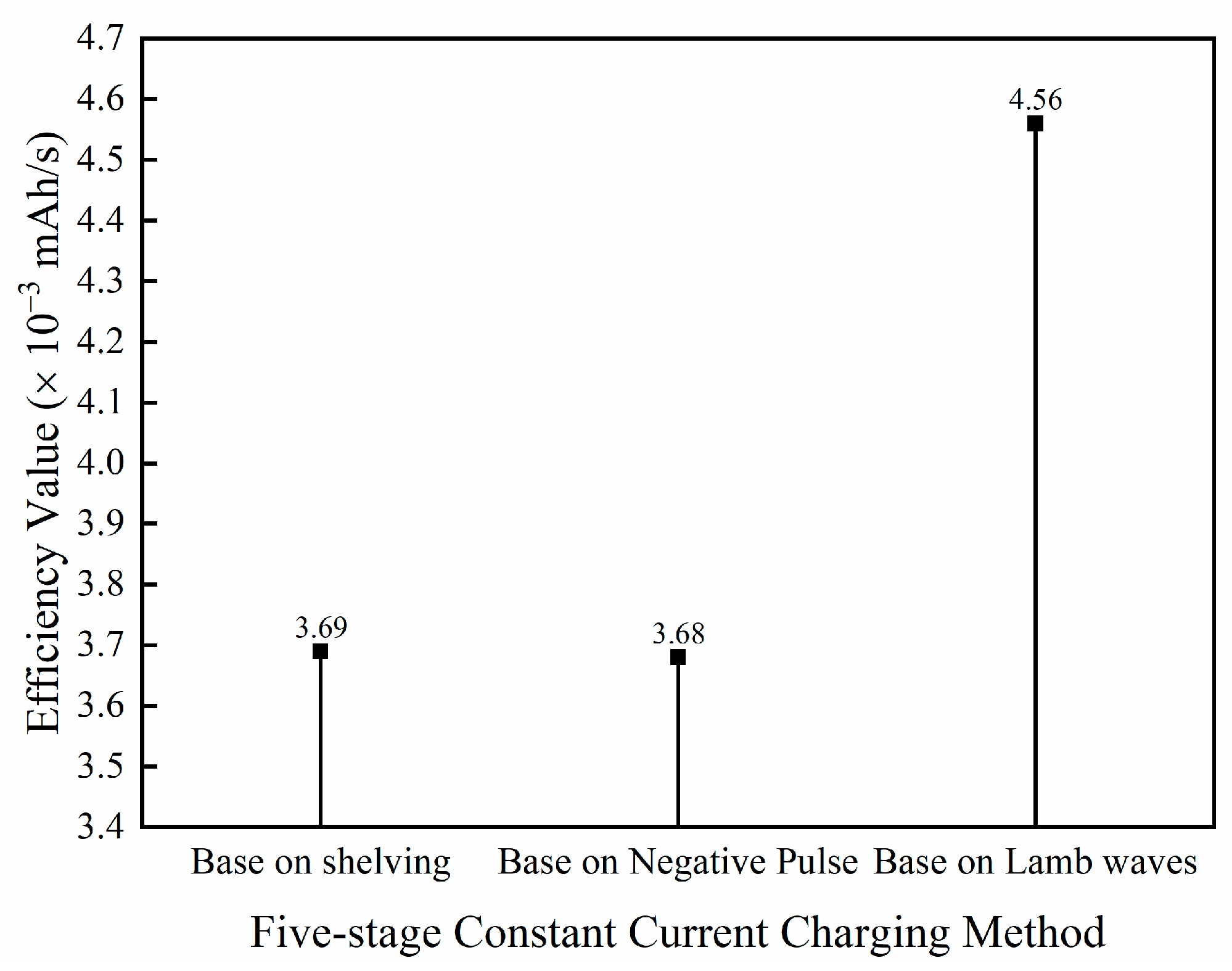
Figure 14 displays the charging efficiency values of three five-stage constant current depolarization charging methods. It is evident that the charging efficiency of the five-stage constant current charging method utilizing Lamb wave action depolarization is significantly higher than that of the five-stage constant current shelving depolarization method and the five-stage constant current negative pulse depolarization method. The charging efficiency values of the five-stage constant current shelving depolarization method and the five-stage constant current negative pulse depolarization method are nearly identical. The charging efficiency of the Lamb wave depolarization five-stage constant current charging method is 23.58% higher than that of the five-stage constant current shelving depolarization charging method. Similarly, the charging efficiency of the Lamb wave depolarization five-stage constant current charging method is 23.91% higher than that of the five-stage constant current negative pulse depolarization method. Therefore, the five-stage constant current charging method of Lamb wave action depolarization is more efficient than the traditional five-stage constant current depolarization charging method.

5. Conclusions

This paper proposes a five-stage constant current charging method based on Lamb wave depolarization to enhance the charging efficiency. The results show that compared with the traditional five-stage constant current charging method, the five-stage constant current charging method based on Lamb wave depolarization shortens the charging time and increases the charging capacity. The effects of Lamb wave excitation duration and excitation voltage on enhancing the battery charging efficiency are then discussed. It is found that as the Lamb wave excitation voltage gradually increases, the charging efficiency also gradually increases. At the same time, the weakening of the polarization effect is positively correlated with the excitation voltage of Lamb waves. In addition, compared to the existing five-stage constant current shelving depolarization charging method and the five-stage constant current negative pulse depolarization charging method, the charging efficiency of the five-stage constant current charging method based on Lamb wave depolarization is higher. In future research, we will investigate the application of the proposed five-stage constant current charging method based on Lamb wave depolarization on larger capacity batteries and battery packs.

Author Contributions

Conceptualization, T.W. and W.L.; methodology, T.W.; validation, T.W.; formal analysis, W.L.; investigation, T.W.; resources, W.L.; writing—original draft preparation, T.W. and W.L.; writing—review and editing, T.W. All authors have read and agreed to the published version of the manuscript.

Funding

This research was funded by the National Natural Science Foundation of China, grant number (51505274).

Data Availability Statement

The original contributions presented in the study are included in the article, further inquiries can be directed to the corresponding author.

Conflicts of Interest

The authors declare no conflicts of interest.

References

  1. Scrosati, B.; Garche, J. Lithium batteries: Status, prospects and future. J. Power Sources 2010, 195, 2419–2430. [Google Scholar] [CrossRef]
  2. Rao, Z.; Wang, S.; Zhang, G. Simulation and experiment of thermal energy management with phase change material for ageing LiFePO4 power battery. Energy Convers. Manag. 2011, 52, 3408–3414. [Google Scholar]
  3. Caban, J.; Małek, A.; Šarkan, B. Strategic model for charging a fleet of electric vehicles with energy from renewable energy sources. Energies 2024, 5, 1264. [Google Scholar] [CrossRef]
  4. Seddig, K.; Jochem, P.; Fichtner, W. Two-stage stochastic optimization for cost-minimal charging of electric vehicles at public charging stations with photovoltaics. Appl. Energy 2019, 242, 769–781. [Google Scholar] [CrossRef]
  5. Saw, L.H.; Ye, Y.; Tay, A.A.O. Integration issues of lithium-ion battery into electric vehicles battery pack. J. Clean. Prod. 2016, 113, 1032–1045. [Google Scholar] [CrossRef]
  6. Lee, C.H.; Chen, M.Y.; Hsu, S.H.; Jiang, J.A. Implementation of an SOC-based four-stage constant current charger for Li-ion batteries. J. Energy Storage 2018, 18, 528–537. [Google Scholar] [CrossRef]
  7. Liu, Y.H.; Teng, J.H.; Lin, Y.C. Search for an optimal rapid charging pattern for lithium-ion batteries using ant colony system algorithm. IEEE Trans. Ind. Electron. 2005, 52, 1328–1336. [Google Scholar] [CrossRef]
  8. Hussein, A.A.H.; Batarseh, I. A review of charging algorithms for nickel and lithium battery chargers. IEEE Trans. Veh. Technol. 2011, 60, 830–838. [Google Scholar] [CrossRef]
  9. Shen, W.; Vo, T.T.; Kapoor, A. Charging algorithms of lithium-ion batteries: An overview. In Proceedings of the 2012 7th IEEE Conference on Industrial Electronics and Applications (ICIEA), Singapore, 18–20 July 2012; pp. 1567–1572. [Google Scholar]
  10. Koleti, U.R.; Bui, T.N.M.; Dinh, T.Q.; Marco, J. The development of optimal charging protocols for lithium-ion batteries to reduce lithium plating. J. Energy Storage 2021, 39, 102573. [Google Scholar] [CrossRef]
  11. Bui, T.M.; Sheikh, M.; Dinh, T.Q.; Gupta, A.; Widanalage, D.W.; Marco, J. A study of reduced battery degradation through state-of-charge pre-conditioning for vehicle-to-grid operations. IEEE Access 2021, 9, 155871–155896. [Google Scholar] [CrossRef]
  12. Ikeya, T.; Sawada, N.; Murakami, J.; Kobayashi, K.; Hattori, M.; Ujiie, S.; Kajiyama, K.; Nasu, H.; Narisoko, H.; Tomaki, Y.; et al. Multi-step constant-current charging method for an electric vehicle nickel/metal hydride battery with high-energy efficiency and long cycle life. J. Power Sources 2002, 105, 6–12. [Google Scholar] [CrossRef]
  13. Dung, L.R.; Yen, J.H. ILP-based algorithm for Lithium-ion battery charging profile. In Proceedings of the 2010 IEEE International Symposium on Industrial Electronics, Bari, Italy, 4–7 July 2010; pp. 2286–2291. [Google Scholar]
  14. Zhang, S.S. The effect of the charging protocol on the cycle life of a Li-ion battery. J. Power Sources 2006, 161, 1385–1391. [Google Scholar] [CrossRef]
  15. Liu, Y.H.; Hsieh, C.H.; Luo, Y.F. Search for an optimal five-step charging pattern for Li-ion batteries using consecutive orthogonal arrays. IEEE Trans. Energy Convers. 2011, 26, 654–661. [Google Scholar] [CrossRef]
  16. Hsieh, G.C.; Chen, L.R.; Huang, K.S. Fuzzy-controlled Li-ion battery charge system with active state-of-charge controller. IEEE Trans. Ind. Electron. 2001, 48, 585–593. [Google Scholar] [CrossRef]
  17. Jin, Q.Y. Design of Fast Charge System for Lithium-Ion Batteries. Master’s Thesis, Hunan University, Changsha, China, 2017. [Google Scholar]
  18. Kannan, D.R.R.; Weatherspoon, M.H. The effect of pulse charging on commercial lithium nickel cobalt oxide (NMC) cathode lithium-ion batteries. J. Power Sources 2020, 479, 229085. [Google Scholar] [CrossRef]
  19. Lu, Y.H.; Deng, J. Design and implementation of a fast charging method for lithium batteries. Electron. Des. Eng. 2020, 28, 113–117. [Google Scholar]
  20. Huang, A.; Liu, H.; Manor, O.; Liu, P.; Friend, J. Enabling rapid charging lithium metal batteries via surface acoustic wave-driven electrolyte flow. Adv. Mater. 2020, 32, 1907516. [Google Scholar] [CrossRef]
  21. Connacher, W.; Zhang, N.; Huang, A.; Mei, J.; Zhang, S.; Gopesh, T.; Friend, J. Micro/nano acoustofluidics: Materials, phenomena, design, devices, and applications. Lab Chip 2018, 14, 1952–1996. [Google Scholar] [CrossRef]
  22. Li, H.; Friend, J.R.; Yeo, L.Y. Surface acoustic wave concentration of particle and bioparticle suspensions. Biomed. Microdevices 2007, 9, 647–656. [Google Scholar] [CrossRef]
  23. Su, Z.; Ye, L.; Lu, Y. Guided Lamb waves for identification of damage in composite structures: A review. J. Sound Vib. 2006, 295, 753–780. [Google Scholar] [CrossRef]
  24. Liang, W.; Lindner, G. Investigations of droplet movement excited by Lamb waves on a non-piezoelectric substrate. J. Appl. Phys. 2013, 114, 044501. [Google Scholar] [CrossRef]
  25. Gan, T.H.; Hutchins, D.A.; Billson, D.R.; Schindel, D.W. The use of broadband acoustic transducers and pulse-compression techniques for air-coupled ultrasonic imaging. Ultrasonics 2001, 39, 181–194. [Google Scholar] [CrossRef] [PubMed]
  26. Alghane, M.; Chen, B.X.; Fu, Y.Q.; Li, Y.; Luo, J.K.; Walton, A.J. Experimental and numerical investigation of acoustic streaming excited by using a surface acoustic wave device on a 128° YX-LiNbO3 substrate. J. Micromech. Microeng. 2010, 21, 015005. [Google Scholar] [CrossRef]
  27. Dong, W. Research on Management Technology of Lithium Battery Remaining Power in Electric Vehicle. Master’s Thesis, Shenyang Ligong University, Shenyang, China, 2012. [Google Scholar]
  28. Tietze, S.; Reißenweber, M.; Schlemmer, J.; Lindner, G. Investigation of the surface condition of an electrode after electropolishing under the influence of surface acoustic waves. Phys. Procedia 2015, 70, 1039–1042. [Google Scholar] [CrossRef]
  29. Chen, Y. Inhibition of Lithium Dendrites via Manipulating Chemical Reaction and Diffusion. Ph.D. Thesis, University of Chinese Academy of Sciences, Beijing, China, 2019. [Google Scholar]
  30. Han, J.G.; Jeong, M.Y.; Kim, K.; Park, C.; Sung, C.H.; Bak, D.W.; Kim, K.H.; Jeong, K.M.; Choi, N.S. An electrolyte additive capable of scavenging HF and PF5 enables fast charging of lithium-ion batteries in LiPF6-based electrolytes. J. Power Sources 2020, 446, 227366. [Google Scholar] [CrossRef]
  31. Bai, T. Research on the Optimization Fast Charging Method of Lithium-Ion Battery with Intermittent-Positive and Negative Pulse. Master’s Thesis, Hubei University of Technology, Wuhan, China, 2014. [Google Scholar]
  32. Chen, Y. The Study of Fast-Charging Control Strategy of Lithium-Ion Battery on Electrical Vehicle. Master’s Thesis, Jiangnan University, Wuxi, China, 2018. [Google Scholar]
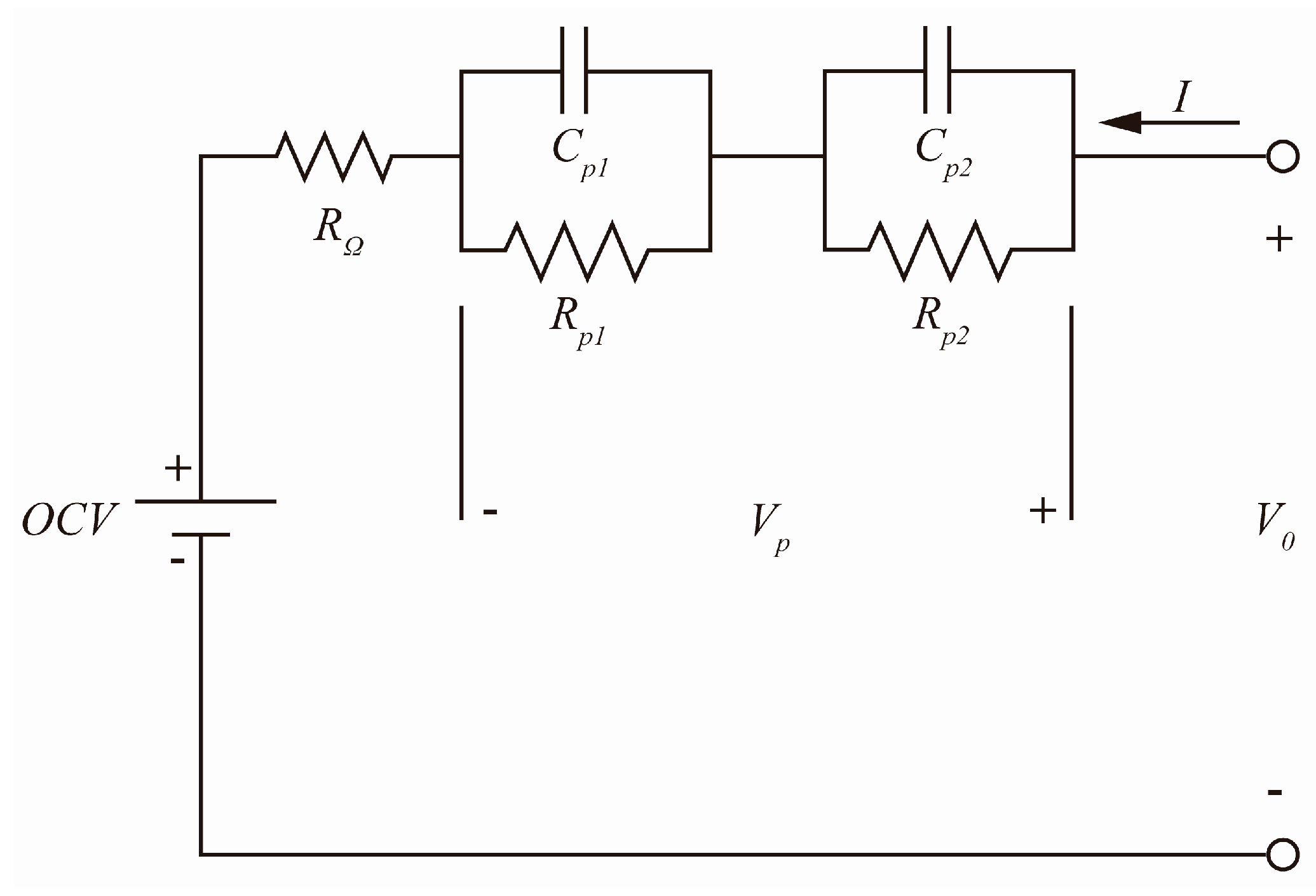
Figure 1. Second–order RC equivalent circuit model of lithium battery.
Energies 17 02992 g001
Figure 2. Schematic diagram of the experimental setup. The black line in the figure represents the wire connected to the negative pole of the homemade amplifier circuit, while the red line represents the wire connected to the positive pole of the homemade amplifier circuit.
Energies 17 02992 g002
Figure 3. Charging time and voltage under different Lamb wave excitation times.
Energies 17 02992 g003
Figure 4. Charging capacity under different Lamb wave excitation times.
Energies 17 02992 g004
Figure 5. Charging time values under different Lamb wave excitation times.
Energies 17 02992 g005
Figure 6. Charging efficiency values under different Lamb wave excitation times.
Energies 17 02992 g006
Figure 7. Charging time and voltage under different Lamb wave excitation voltages.
Energies 17 02992 g007
Figure 8. Charging capacity under different Lamb wave excitation voltages.
Energies 17 02992 g008
Figure 9. Charging time values under different Lamb wave excitation voltages.
Energies 17 02992 g009
Figure 10. Charging efficiency values under different Lamb wave excitation voltages.
Energies 17 02992 g010
Figure 11. Charging efficiency improvement percentage under different Lamb wave excitation voltages.
Energies 17 02992 g011
Figure 12. Battery terminal voltage under different Lamb wave excitation voltages.
Energies 17 02992 g012
Figure 13. Battery terminal voltage drop values under different Lamb wave excitation voltages.
Energies 17 02992 g013
Figure 14. Percentage improvement of five stage constant current charging efficiency based on different depolarization methods.
Energies 17 02992 g014
Table 1. Parameters of LIR1220.
Capacity
(mAh)
Nominal Voltage (V)Cut-off Charging Voltage (V)Cut-off Discharging Voltage (V)Thickness (mm)Diameter (mm)Weight
(g)
103.64.22.752121.1
Table 2. Alternative charging current values for each charging stage.
No.Alternative Current Value (Unit in C Rate)
12.01.951.91.851.8
21.751.71.651.61.55
31.51.451.41.351.3
41.251.21.151.11.05
510.950.90.850.8
Table 3. Orthogonal table L18(35).
No.Level
111111
211222
311333
412112
512223
612331
713121
813232
913313
1021133
1121211
1221322
1322123
1422231
1522312
1623132
1723213
1823321
Table 4. Alternative charging current values at each stage after the first iteration.
LevelAlternative Current Value (Unit in C Rate)
I1I2I3I4I5
12.01.751.51.251
21.91.651.41.150.9
31.81.551.31.050.8
Table 5. Alternative charging current values at each stage after the fourth iteration.
LevelAlternative Current Value (Unit in C Rate)
I1I2I3I4I5
12.01.71.51.250.75
21.951.651.451.20.7
31.91.61.41.150.65
Table 6. Battery terminal voltage drop value (V) under different Lamb wave excitation voltages.
Excttion Voltage (Vpp)Time (s)
102030405060708090
800.02980.05610.07130.08210.08990.09390.0980.09920.1011
1000.03290.06020.08160.09360.10140.10480.10540.10690.1076
1200.03930.0660.08180.09520.10360.10980.11290.1160.1169
Disclaimer/Publisher’s Note: The statements, opinions and data contained in all publications are solely those of the individual author(s) and contributor(s) and not of MDPI and/or the editor(s). MDPI and/or the editor(s) disclaim responsibility for any injury to people or property resulting from any ideas, methods, instructions or products referred to in the content.