Article

Innovative High-Induction Air Diffuser for Enhanced Air Mixing in Vehicles and Personalized Ventilation Applications

by
Florin Ioan Bode
1,2,
Titus Otniel Joldos
1,3,
Gabriel Mihai Sirbu
4,
Paul Danca
2,5,*,
Costin Cosoiu
6 and
Ilinca Nastase
2,*
1
Mechanical Engineering Department, Faculty of Automotive, Mechatronics and Mechanics, Technical University of Cluj-Napoca, 400641 Cluj-Napoca, Romania
2
Advanced Research Center for Ambiental Quality and Building Physics (CAMBI) Research Center, Technical University of Civil Engineering Bucharest, 020396 Bucharest, Romania
3
Ruck Ventilatoare, 545600 Tarnaveni, Romania
4
Renault Technologie Roumanie, Group Renault Romania, 062204 Bucharest, Romania
5
National Institute for R&D in Electric, Engineering ICPE-CA, 030138 Bucharest, Romania
6
Aerodynamics and Wind Engineering Laboratory “Constantin Iamandi” (LAIV), Technical University of Civil Engineering Bucharest, 020396 Bucharest, Romania
*
Authors to whom correspondence should be addressed.
Energies 2024, 17(12), 2930; https://doi.org/10.3390/en17122930
Submission received: 26 May 2024 / Revised: 10 June 2024 / Accepted: 12 June 2024 / Published: 14 June 2024
(This article belongs to the Special Issue Thermal Comfort, Environment Quality and Energy Consumption)

Abstract

:
Thermal comfort is very important for the well-being and safety of vehicle occupants, as discomfort can elevate stress, leading to distracted attention and slower reaction times. This creates a riskier driving environment. Addressing this, high-induction air diffusers emerge as a significant innovation, enhancing indoor environmental quality (IEQ) by efficiently mixing cool air from the heating ventilation and air conditioning (HVAC) system with the cabin’s ambient air. This process ensures uniform airflow, diminishes temperature discrepancies, prevents draft sensations, and boosts overall air quality by improving air circulation. In addition to enhancing thermal comfort in vehicles, the novel air diffuser also offers significant potential for personalized ventilation systems, allowing for individualized control over airflow and temperature, thereby catering to the specific comfort needs of each occupant. This study introduces a novel air diffuser that demonstrates a 48% improvement in air entrainment compared to traditional diffusers, verified through Ansys Fluent simulations and laser Doppler velocimetry (LDV) measurements. At a fresh airflow rate of 31.79 m3/h, the total air entrainment rate at 0.6 m for the standard air diffuser is 73.36 m3/h, while for the innovative air diffuser, it is 109.26 m3/h. This solution has the potential to increase the level of thermal comfort and air quality within vehicles, and also signals potential applications across various enclosed spaces, underscoring its importance in advancing automotive safety and environmental standards.

1. Introduction

Air distribution is a critical aspect of indoor environmental quality (IEQ) in vehicles, especially in enclosed spaces such as automobiles, trains, buses, and airplanes. This is because it has a large weight to the comfort and well-being of passengers and crew members. Inadequate IEQ can cause health problems and discomfort, and this can accelerate fatigue of the users, which can affect the ability to respond to various stimuli by increasing the user reaction time, which can lead to the occurrence of unwanted and unpleasant events. For example, in [1] the authors demonstrated that under low humidity conditions, drivers exhibited a higher accuracy in response rate and experienced less overall fatigue compared to situations with higher humidity.
Personalized ventilation in office buildings is increasingly recognized as a crucial factor in enhancing indoor environmental quality (IEQ) and occupant productivity [2]. Traditional HVAC systems often fail to address the diverse thermal preferences and metabolic rates of individual occupants, leading to discomfort and decreased performance. Even if ideal environmental conditions were created according to Fanger’s theory [3], aiming for a predicted mean vote (PMV) of 0, it would still be observed that a certain percentage of occupants would remain dissatisfied. Fanger’s predicted percentage of dissatisfaction (PPD) index indicates that at a PMV of 0, approximately 5% of people are likely to be dissatisfied with their thermal environment. This inherent variability in individual thermal comfort underscores the limitations of traditional HVAC systems and the need for more adaptable solutions.
Personalized ventilation systems offer a solution by allowing individuals to control their immediate microenvironment, adjusting airflow and temperature to their specific needs. This tailored approach can reduce the risk of discomfort [4] and health issues associated with poor air quality, such as headaches, dry eyes, and respiratory problems [5]. Studies have shown that providing employees with the ability to customize their ventilation can lead to significant improvements in cognitive function, concentration, and overall job satisfaction. For instance, the research highlighted in [6] acknowledged that the ability to personally control ventilation is a significant factor in enhancing satisfaction with thermal comfort, owing to both its physical benefits and positive psychological effects. For example, in building offices, worker well-being and productivity are highly influenced by workplace conditions. Therefore, it is essential to ensure high indoor environmental quality (IEQ). A key parameter of IEQ is thermal comfort, which is maintained by heating, ventilation, and air conditioning (HVAC) systems [7].
Thermal comfort is commonly understood as the state of satisfaction a person experiences regarding the temperature and environment within an occupied space, this evaluation being a subjective one. Nevertheless, a precise definition is challenging, and conceiving a universal definition becomes even more complex due to the intertwined nature of human physical and psychological states [8].
In the last years, the focus on enhancing thermal comfort in vehicles has intensified, coinciding with a significant rise in the time vehicle occupants spend in traffic [9,10]. Specialists and researchers in the HVAC field are constantly looking for new models to estimate, predict, or classify the state of thermal comfort in occupied spaces [11,12,13]. The study in [14] confirmed that thermal sensation is the most commonly utilized metric in the thermal comfort database II [14], appearing frequently as a central question in almost all thermal comfort research, succeeded by topics such as thermal comfort, thermal preference, and thermal acceptability. Many scientific investigations have prioritized the physiological aspect of thermal comfort, operating under the assumption that it is achievable when the human body’s excess heat is released into the environment, rendering the human thermoregulatory system insignificant.
Passenger comfort in vehicles is of great interest as it directly affects the well-being, safety, and overall travel experience of the occupants. Studies have shown that maintaining optimal comfort levels can significantly reduce fatigue and improve cognitive function, which is critical for ensuring the safe and alert operation of vehicles [15,16]. For instance, research on the thermal comfort of passengers in trains has highlighted the necessity of thermal comfort and its impact on passenger satisfaction and performance [17,18]. Similarly, in airplanes, maintaining a comfortable cabin environment is very important for passenger health and well-being during long flights [19,20]. Additionally, in buses, ensuring a comfortable atmosphere is also important for passenger satisfaction and can reduce the stress associated with travel [18,21]. These studies collectively underscore the need for advanced ventilation systems and improved air diffuser designs to enhance passenger comfort across various modes of transportation.
However, studying thermal comfort in vehicle cabins is challenging due to the intensely severe thermal transient states caused by the HVAC system, high air velocities, high thermal gradients, and radiative heat flow. Moreover, differences in cabin volume, glazing area, occupant posture, and physiological factors make estimating thermal comfort even more difficult. Multiple methods exist to enhance thermal comfort within vehicles, including using the HVAC system, ventilating seats, and heated chairs [22]. Considering that the HVAC system has been identified as the principal system affecting occupants’ thermal comfort, more attention should be directed towards this system.
As previously mentioned, when considering the distinct environmental attributes of vehicles, a notable disparity arises when compared to conventional indoor settings. Vehicle cabins have considerably reduced volumes and can accommodate a greater number of individuals per square meter than in a building case, for example. Furthermore, when assessing the velocity at which the HVAC system introduces fresh air, it becomes apparent that the rate of air changes per hour (ACH) is significantly increased in vehicles compared with building cases. This contrast emphasizes that the flow of air within a vehicle primarily responds to the thermal load primary and is not connected to the indoor air quality (IAQ) within the vehicle.
Chang et al. [23] confirmed the necessity of having at least 32.4 m3/h per person (9.21 L/s), which, as known from the measurements, corresponds to a very low ventilation rate in the vehicle. They measured the CO2 levels within a vehicle and found that following the ASHRAE standard 62.1 guideline, which recommends an outdoor air supply rate of 2.5 L/s per person, results in an average CO2 concentration of roughly 2850 ppm in the vehicle cabin. Elevating the air supply rate to 4.0 L/s and 9.21 L/s per person, with the goal of improving occupant well-being, was shown to decrease the average CO2 concentrations to approximately 1810 ppm and 1000 ppm (considered a safe threshold), respectively [23].
Hence, it can be concluded that enhancing the thorough mixing of fresh air with the surrounding atmosphere presents a potential solution to enhance thermal comfort for occupants within vehicles. This becomes especially significant when taking into account that in summer, the fresh air temperature issued by the heating, ventilation, and air conditioning system of a vehicle can drop below 10 °C [24], effectively mitigating or, at the very least, diminishing the perception of drafts felt by the passengers within the vehicle. As a result, strategies aimed at optimizing the distribution of air and guaranteeing a more balanced mixture of fresh and ambient air become essential in creating an optimal thermal comfort setting within vehicles.
Moreover, the methodology employed in this research revolves around enhancing the passive mixing of fresh air intake with the vehicle’s interior ambient air. The primary goal is to decrease the temperature and diminish the velocity of this airflow, as these two variables significantly influence both thermal comfort and the sensation of draughts experienced by passengers in vehicles or occupants in enclosed spaces [25]. The significance of thermal comfort during driving is crucial for all individuals; however, Feng et al. [26] highlighted that women possess a lower tolerance for thermal sensations, suggesting that thermal comfort may hold greater importance for this demographic.
To attain this objective, an extensive numerical analysis was conducted, which involved the comparison of different air diffuser designs with the aim of identifying a more efficient passive mixing system than the conventional ones typically employed in the automotive industry. The ventilation system in vehicles plays a critical role in providing a steady supply of fresh air and removing the pollutants from the ambient air by diluting it. High-induction air diffusers with lobed orifices are a promising solution for improving IEQ in vehicles [27]. The same conclusion was pointed out in [28], where these air diffusers supply fresh air into the ventilated enclosure and mix it with the existing ambient air, thereby lowering pollutant levels and enhancing the overall IEQ. The idea of using lobed orifices in ventilation in terms of high induction is not new. The utilization of the lobed diffuser demonstrated a notable enhancement in thermal comfort when compared to the conventional diffuser [29]. This improvement was achieved without any increase in pressure drop or sound pressure levels.
In [30], the authors studied a flow from a tubular radially lobed nozzle at two Reynolds numbers to explore instability mechanisms and vortex dynamics that enhance mixing, confirming the evolution of Kelvin-Helmholtz-like modes and distinct structural changes compared to round nozzles.
High-induction air diffusers can be a solution for other applications as well, for example in the case of isolation rooms, the positioning of a “turbulence high induction” ceiling air diffuser for air inlet is of utmost importance [31]. The results indicate the ideal conditions for the high-induction air inlet diffuser and the applied pressure scheme in the room, presenting an efficient method for managing airflow that contains virus droplets. In [32], the numerical outcomes of four distinct air diffuser geometries were evaluated in comparison to one another, including the original diffuser for the air installed in the Dacia Duster vehicle produced by Renault Group. Among them, the best-studied case, which basically involves the arrangement of three concentric circles with lobes accompanied by guide blades at varying angles, where the lobes are located on the air diffuser’s outer section, emerged as the most effective in terms of entraining in ambient air, exhibiting a 35% increase in air mixing compared to the reference air diffuser. Based on the findings of this research and after a careful examination of the results, the air diffuser geometry was changed, and in a later study [33], four different novel variants of vehicle air diffusers were compared with the reference one, and the best diffuser had 41% more air induction compared with the reference one. Later, using the same technique, in the study [34], the air induction reached 43%.
Although the studies reviewed in this paper have predominantly focused on the development of air diffusers for the automotive industry, these diffusers can also be effectively utilized in personalized ventilation applications. Due to their ability to provide individualized control over airflow and temperature, the findings and innovations presented in this article are applicable to both automotive and personalized ventilation systems. This dual applicability highlights the versatility of the enhanced air diffusers, ensuring that the improvements in air entrainment and thermal comfort can benefit not only the vehicle occupants but also individuals in various enclosed spaces, such as office buildings.
This study is part of a larger research project aimed at developing high-induction air diffusers tailored for vehicle ventilation systems. It investigates various innovative air diffuser designs that surpass traditional models in air mixing efficiency, potentially transforming airflow dynamics within vehicles to improve temperature comfort and reduce air velocity. The main focus of this study is on a particularly promising diffuser design, evaluating its unique features and the significant improvement it offers in driving comfort through the improved integration of fresh air into the vehicle’s internal environment. This involves achieving more consistent airflow temperatures and reducing velocity, both with great impact on thermal comfort and minimizing draught sensations.
Furthering previous inquiries, this research compares different high-induction air diffuser geometries to identify an optimal passive mixing solution for the automotive sector. The present study presents the development and testing of a new air diffuser model that promises to elevate thermal comfort across various vehicles, including electric ones. Experimental validation was conducted on a Dacia Renault Duster, thanks to a partnership with a leading automotive manufacturer, demonstrating the generalizability of these findings. The study emphasizes the importance of experimental data to support numerical predictions, with validated results on a specific vehicle model offering broad applicability across different vehicle types. This reflects the universal relevance of this study’s findings to the domain of automotive thermal comfort, highlighting the comparable design and functionality of HVAC systems and air diffusers in vehicles with diverse powertrains.
The novelty of this work lies in the development and evaluation of an innovative high-induction air diffuser specifically designed for vehicle applications, demonstrating an increase in air entrainment compared to traditional models. This study uniquely combines advanced numerical simulations with experimental validations using laser Doppler velocimetry (LDV) to verify the performance enhancements. The new diffuser design aims to improve thermal comfort by ensuring the improved mixing of fresh and cabin air. Furthermore, the principles and design innovations introduced have broad applications, extending beyond automotive use to personalized ventilation systems in various enclosed environments, thereby contributing significantly to the fields of indoor air quality and thermal comfort.

2. Materials and Methods

2.1. General Context

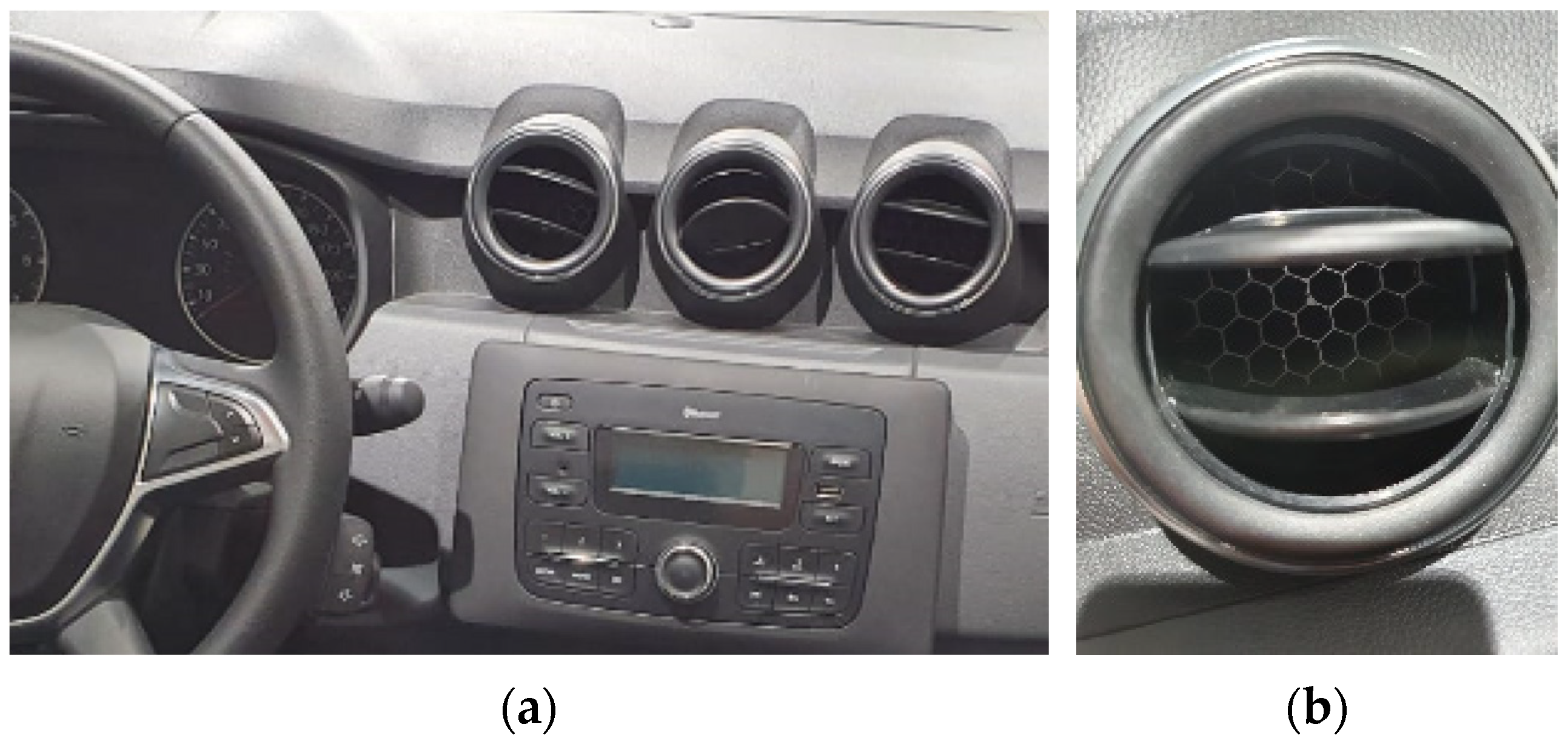
The present article describes the implementation of the numerical studies, which were within the context of a joint research initiative between the Renault Technologie Roumanie (RTR) and the Technical University of Civil Engineering Bucharest (UTCB). One of the objectives of these studies was to investigate and analyze various aspects related to the Dacia/Renault Duster vehicle ventilation system. Under the research project, a comprehensive examination of the Dacia/Renault Duster was conducted using advanced numerical techniques using the computational fluid dynamics (CFD) technique. These numerical studies involved simulations and analyses aimed at exploring different aspects of using high-induction air diffusers for the Renault Duster vehicle. Figure 1 presents the central part of the Dacia/Renault Duster dashboard (Figure 1a) and the original air diffusers (Figure 1b).
A new geometry, designed to passively induce greater airflow, was initially developed with La Rochelle University in France [35] and the University of Rennes [24]. The lobed shape considered in the previous studies was adapted to fit the Duster dashboard.
The geometries under analysis were constructed using SolidWorks software and subsequently imported into the Ansys Workbench for the purpose of preparing the cases for the numerical simulations.

2.2. Numerical Approach

The numerical investigation in this study was conducted utilizing the Ansys software package 19.2, with the Fluent solver employed for the numerical simulation of fluid flow. This computational approach allowed us to analyze and optimize various air diffuser geometries, following different strategies as part of the research team’s effort to develop an enhanced ambient air induction system. Numerical simulations were performed for the air diffuser integrated into the Dacia/Renault Duster vehicle to obtain a baseline of the new geometries.

2.2.1. Air Diffuser Geometries

As mentioned in the introduction part, the first study was carried out by the project research team in [32], in which a high-induction air diffuser was conceived with a capability of 35% greater air mixing compared to the reference Dacia/Renault Duster air diffuser.
Based on the feedback received from the obtained results in [32], new strategies were employed by the research team in order to increase the induction rate for the same input parameters, and four new air diffusers were designed, taking all these observations into consideration [33], with one of them having an increased air induction of 41% compared to the reference air diffuser.
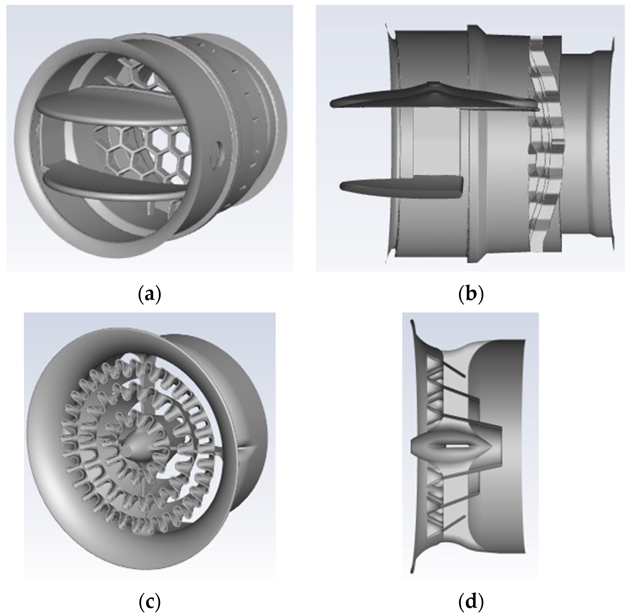
Figure 2a,b (case A) shows the original dashboard diffuser for the air present in the Dacia/Renault Duster. The work progressed with a continued focus on refining the diffuser geometry based on the insights gathered from all the numerical results through a comprehensive numerical simulation process, which involved evaluating and understanding the flow behavior of each individual geometry. This final geometry was poised for further testing and analysis in the subsequent phases of the research Figure 2c,d (case X).
The numerical simulation accounted for just half of the domain, recognizing the geometry’s symmetry along the flow’s longitudinal axis. Air diffuser models were created in SolidWorks and then transferred to the Ansys 19.2 Workbench through the Space Claim CAD software included in the Ansys 19.2 package. The domain’s segment, ranging from the air diffuser’s top to the outlet, spanned a height of 800 mm and encompassed a diameter of 1000 mm. With a 400 mm length and a 65 mm diameter, the duct channelled air to the diffuser at its terminus, dispersing the air into the room.

2.2.2. Numerical Grid

The numerical grid generation process strategy involved the use of two stages. First, Ansys meshing was employed to generate a tetrahedral mesh. Following this, the mesh generated earlier underwent a conversion into a polyhedral mesh utilizing Ansys Fluent 19.2 software. Based on the previous findings and confirmed in this study, employing this two-stage meshing working procedure enables the generation of high-quality numerical grids within a limited timeframe. Their automatic generation capability allows for a more streamlined and time-efficient meshing process. This approach offers several advantages.
Polyhedral numerical grids offer a unique set of advantages that make them an excellent choice for simulating complex fluid flows within the framework of the research presented in the article. Firstly, they combine the reduced numerical diffusion characteristics typically associated with hexahedral meshes with the automatic generation capability inherent in tetrahedral grids [36]. This hybrid nature allows for the accurate representation of complex geometries while minimizing numerical artifacts, ensuring that the simulation results closely align with real-world physical phenomena.
Moreover, polyhedral grids demonstrate remarkable resilience to mesh stretching, which often occurs in confined or intricate geometries [37]. This characteristic results in improved mesh quality, reducing the occurrence of skewed or distorted elements. Improved mesh quality, in turn, directly contributes to the numerical stability of the simulation. The mesh stability achieved with polyhedral grids is particularly critical when dealing with the intricate flow patterns and heat transfer processes found within vehicle cabins and confined spaces. It ensures that the simulation accurately captures the intricate flow dynamics without numerical instabilities that could compromise the accuracy of the results.
An additional significant benefit of polyhedral meshes lies in their capability to reduce numerical diffusion. This property, akin to the highly desirable hexahedral grids, significantly enhances the precision of the simulation. Reduced numerical diffusion means that the solution is less prone to the amplification of numerical errors, resulting in a more accurate representation of the physical flow behavior [37]. In the context of the research focused on enhancing the IAQ and occupants’ thermal comfort, maintaining accuracy is very important in providing actionable insights for improving vehicle cabin design and occupant well-being.
The grid independence test was performed in [32] for a similar geometry. Considering that the flow regime and boundary conditions are identical and the geometry design has similar features, the same rules were considered for the mesh generation. A mesh refinement was applied to all the numerical grids in the area after the air diffuser. The refinement employed a zone in the form of a cone with an element size of 0.7 mm. Moreover, the air diffuser’s interior surfaces were precisely set to have an element size of 0.2 mm. The resulting mesh, consisting of about 109 million tetrahedral elements (Case V), was imported into Ansys Fluent, where it underwent a conversion process to transform it into a polyhedral grid. This conversion resulted in a final mesh comprising about 21.536 million polyhedral elements. A boundary layer, consisting of eight layers and featuring a growth rate of 1.1, was established for all wall surfaces. The numerical simulation conducted with this mesh configuration resulted in a maximum y+ value of 1.9, which was found in a zone far away from the interest zone. The y+ maximum number in the lobed area was 1.35 and fulfilled the y+ criterion of the SST model, specifically a y+ value of approximately 1 [38].
The numerical grid for the original air diffuser was generated using the same settings and controls as described earlier. However, considering the varying level of detail required for each air diffuser, the mesh size differed accordingly. For instance, the numerical grid used in the case of the original air diffuser (case A) presented in Figure 2a,b had a number of 7.021 million cells (polyhedral) derived from an initial tetrahedral mesh comprising 23.355 million tetrahedral elements.

2.2.3. Numerical Setup

At the boundary, an airflow inlet condition of 31.2 m3/h (0.010609 kg/s) was imposed as the mass flow inlet boundary condition. This rate aligns with the second speed setting of the HVAC system, the highest being four.
In the Dacia/Renault Duster vehicle, there are five air diffusers located on the dashboard, with the chosen air diffuser positioned centrally on the left side. The calculated airflow rate passing the central air diffuser accounts for 21.9% of the overall airflow from the HVAC system, taking into account all air diffusers on the dashboard. The airflow rates through all the air diffusers for the 2nd speed of the HVAC fan can be seen in Table 1 (where L stands for left, R is for right, C is for central, and D is for air diffuser). The tested air diffuser is highlighted with a grey background.
A symmetrical plane was introduced to divide the entire geometry into two equal parts, ensuring symmetric conditions.
The boundary condition at the outlet was established as a pressure outlet. The boundary condition for the remainder of the surfaces was a wall.
The SST k-ω viscous model was utilized for the numerical simulations. The SST k-ω model is renowned for its versatility and robustness, particularly in scenarios involving complex and confined flows [39,40,41], as is the case concerning ventilation in vehicle cabins. This model excels in capturing boundary layer behavior accurately, which is crucial when analyzing airflow patterns associated with high-induction air diffusers. Its unique ability to account for both the near-wall region, where flow behavior is complex, and the free-stream flow contributes significantly to an accurate representation of the entire flow physics within the confined space of a vehicle cabin [39].
Moreover, the k-ω SST viscous model delivers a balance between the k-ε and k-ω models, addressing their individual strengths and weaknesses. It performs exceptionally well in predicting the turbulence near walls, where the flow is most intricate, while also delivering reliable results in the free stream, where flow characteristics vary significantly. This balance ensures that the simulation outcomes remain robust and credible throughout the vehicle cabin, where both near-wall and free-stream airflow interactions are pivotal for achieving improved thermal comfort and air quality. Its capacity to accurately predict turbulence characteristics, including turbulence intensity, length scales, and dissipation rates, enhances the credibility of the simulation results [42].
Additionally, drawing upon the literature [43,44,45], it is affirmed that the SST k-ω viscous model has proven its suitability in simulating these flow conditions, thereby reinforcing its appropriateness for the present investigation.
A complete description of the mathematical model and the basic equations used in the numerical simulation are presented below [39].
The continuity equation ensures mass conservation within the flow field.
ρ t + ( ρ u ) = 0
where ρ is the fluid density, t is time, and u is the velocity vector.
The momentum equation, also known as the Navier–Stokes equation, accounts for the conservation of momentum.
( ρ u ) t + ( ρ uu ) = p + ( μ ( u + ( u ) T ) ) + F
where p is the pressure, μ is the dynamic viscosity, and F represents the body forces (such as gravity).
The energy equation describes the conservation of energy within the system.
( ρ E ) t + ( u ( ρ E + p ) ) = ( k T + ( τ u ) ) + SE
where E is the total energy, k is the thermal conductivity, T is the temperature, τ represents the stress tensor, and SE represents the energy sources.
The SST k-ω model involves two transport equations, one for the turbulence kinetic energy (k) and one for the specific dissipation rate (ω).
  • The formula for the turbulence kinetic energy (k) is as follows:
( ρ k ) t + ( ρ ku ) = P k β * ρ k ω + ( ( μ + σ k μ t ) k )
where Pk is the production of turbulence kinetic energy, β* is a model constant, and μt is the eddy viscosity.
  • The formula for the specific dissipation rate (ω) is as follows:
( ρ ω ) t + ( ρ ω u ) = α ω k P k β ρ ω 2 + ( ( μ + σ ω μ t ) ω )
where α and β are the model constants, and σk and σω are the turbulent Prandtl numbers for k and ω, respectively.
These equations formed the foundation of the numerical simulation and provided a robust framework for analyzing the airflow patterns, turbulence characteristics, and the overall performance of the innovative high-induction air diffuser in the vehicle cabin.
The discretized equations were solved using the finite volume method (FVM), which is widely used in computational fluid dynamics (CFD) for converting partial differential equations into algebraic equations. The numerical solver utilized for this study was the pressure-based solver in Ansys Fluent. This solver is particularly effective for handling incompressible flows, as is the case in the present ventilation simulation.
The SIMPLEs (semi-implicit method for pressure-linked equations) algorithm was employed to handle the pressure–velocity coupling. This method iteratively solves the momentum equations and the pressure correction equation to ensure mass conservation and to update the velocity field.
The spatial discretization for the governing equations, including the continuity, momentum, energy, and turbulence model equations, was achieved using second-order upwind schemes. This approach enhances the accuracy of the solution by reducing numerical diffusion and providing a more precise representation of the flow field.
Convergence criteria were set to ensure that the residuals for all the equations fell below 1 × 10⁻⁶, ensuring a high level of solution accuracy and stability.

2.3. Experimental Measurements

Laser Doppler velocimetry (LDV) measurements were performed to validate the CFD numerical results. The measurement system employed was an LDV system, which integrated a Flow Lite system featuring a single-component HeNe laser and a 2D FiberFlow Ar-Ion laser from Dantec Dynamics. They were used for the comprehensive measurement of all three velocity components. Additionally, three YAG solid sources, emitting beams at 200 mW with distinct wavelengths of 488 nm, 532 nm, and 561 nm, were utilized. These sources were linked to a burst spectrum analyzer (BSA) processor F/P 600 series for analysis. In the present approach, the burst spectrum analyzer (BSA) was employed in the “coincidence” mode. In this mode, two channels are acquired simultaneously, allowing for access to the components of Reynolds stress, namely, ⟨u’v’⟩, ⟨u’w’⟩, or ⟨v’w’⟩.
For this activity, a specially constructed experimental setup was designed to test the air diffuser models. It consisted of an axial fan with airflow rate variation, a silencing chamber, a 1500 mm long and 70 mm diameter duct, a HoneyComb-type zone, and the tested air diffuser. A schematic of the LDV measurement experiment can be seen in Figure 3a, and an image with the experimental setup is presented in Figure 3b.
In contrast to alternative methods, such as hot wires or Pitot tubes, the LDV optical technique relies on the measurement of lightweight seeds carried by the flow, traversing the measurement volume. Careful consideration is crucial in seeding the flow to minimize errors resulting from an asymmetric distribution of these particles. Moreover, the particles must be sufficiently small to accurately represent the fluid movement that propels them. Thus, the measurement environment was seeded with olive oil particles, which were generated using an atomizer and a compressor.
The alignment and calibration of the LDV system were rigorously verified against known standards, providing a benchmark for measurement accuracy. This step was crucial for minimizing the systematic errors that could arise from misalignment or calibration drift over time. In the conducted measurements, olive oil was selected as the tracer substance and atomized using a Dantec Flow Tracker 700PR generator (Dantec Dynamics, Skovlunde, Denmark) powered by compressed air at a maximum pressure of 2 bar. The analysis of particle size distribution, performed using a 1.108 optical counter from Grimm, revealed a range of particle sizes. However, 50% of the particles fell within a diameter of 1 to 2 μm. Furthermore, 91% of the particles had a diameter less than the interfringe spacing (i) of the green and blue beams used in the LDA system. This enhanced the measurement precision by reducing the noise associated with particle visibility ambiguities and facilitated the more effective detection of Doppler frequencies with the burst spectrum analyzer (BSA) [46]. To maintain a relatively constant oil level and prevent significant distribution variations, frequent reloading of the atomizer was ensured.
Images from the air diffuser LDV experiments can be observed in the following figures: Figure 4a for the reference one and Figure 4b for the lobed variant.
In order to use the LDV system in a three-dimensional setup, integrating the measurement volumes of the 2D Fiber Flow system with the 1D Flow Lite system was necessary. This integration required the precise alignment of the probes so that the intersecting beams for all three components converged closely at the same location. A pinhole device with an opening precisely sized to allow the focused beam’s passage was used for the meticulous adjustment of the probe positions to ensure the beams’ intersection points were aligned. The accurate overlay of the measurement volumes was verified through the use of a power meter linked to a photodiode situated behind the pinhole, making the quantitative enhancement of the light power for each beam possible as it passed through the pinhole.
This process involved aligning the probes to ensure that the beam intersections for the three components were approximately at the same “point”. Utilizing a pinhole device, the probe positions were finely adjusted to align the intersection points. The pinhole had an opening just large enough for the focused beam to pass through. The precise alignment of the measurement volume overlay was achieved by employing a power meter connected to a photodiode positioned behind the pinhole. This allowed for the quantitative maximization of the light power passing through the pinhole for each beam.

3. Results and Discussion

3.1. Increasing Air Mixing

When considering the ventilation of vehicles, a pertinent question arises: is the mixing of fresh air with cabin air beneficial for the occupant’s health and comfort? Understanding the dynamics of air exchange in vehicles is very important when addressing this question. In this part of the study, it was investigated whether the high rates of air change typically seen in vehicles, driven by the need to manage thermal loads, actually contribute to better air quality for the occupants or if they simply serve to maintain thermal comfort.
For example, it is known that the suggested frequency of air exchange in building ventilation can vary depending on factors such as the building’s category, its intended purpose, and its compliance with local or international regulations. Nevertheless, as a broad recommendation, it is prudent to target a range of 4–8 full air replacements per hour for residential or office structures. It is essential to recognize that, for buildings, this range serves not only to maintain satisfactory indoor air quality but also plays a substantial role in preserving a wholesome and healthful indoor atmosphere.
Based on the airflow measurements taken with a funnel anemometer (Testo), when discussing air changes per hour (ACH) in vehicles, it was determined that the range can vary from 48 to 144 ACH, depending on the HVAC airflow settings, specifically V1–V4, in the case of the SUV vehicle Dacia/Renault Duster. These values are significantly higher than those typically encountered in building ventilation scenarios, being 12–18 times greater. This discrepancy highlights a very high difference: in vehicles, the airflow rate is more closely correlated with the thermal load to be removed rather than the requirement for fresh air. Consequently, it can be confidently asserted that there is no need for concern regarding the accumulation of unhealthy compounds due to insufficient ventilation, even when using the lowest ventilation setting in a vehicle.
In this assessment, the interior air volume of an unoccupied Dacia/Renault Duster was approximately 2.5456 cubic meters, and with one occupant, it reduced to about 2.487 cubic meters. This calculation formed the basis for the previously mentioned ACH values. It is worth noting that this value has also been corroborated by Renault Technologie Roumanie, part of the Renault group. Therefore, despite the high air exchange rates, the improved mixing of fresh air with cabin air does not influence the air quality experienced by the occupants, as the primary function of this high airflow is to manage thermal loads rather than to increase the fresh air supply.

3.2. Experimental Validation of the Numerical Results

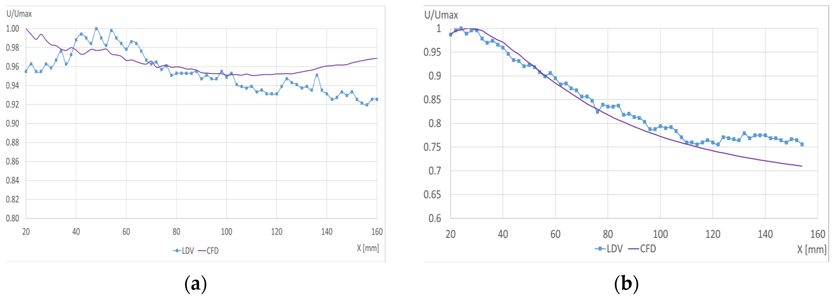
Laser Doppler velocimetry (LDV) measurements were conducted for both air diffusers: the reference (case A) and the lobed configuration (case V). The axial velocity decay was measured in both cases, and the results were compared with the outcomes obtained from the numerical simulations. Figure 5a presents the comparison between the LDV measurements and CFD results for the reference case, and Figure 5 demonstrates the lobed air diffuser results.
A notable resemblance can be observed in the compared values for both the reference diffuser and the lobed diffuser configurations. The maximum error is below 5% for the reference diffuser and is a maximum of 6% for the lobed diffuser case.
Furthermore, a significant reduction in velocity is evident with the lobed diffuser, consistent with the preliminary hypotheses. Thus, with an increase in the entrainment rate, a drop in velocity is anticipated because of the momentum exchange between the jet air and the surrounding air. This trend is consistent with the initial assumptions and with the numerical results regarding the lobed diffuser behavior and confirms the significant influence of the entrainment rate on the velocity profile in this specific context.

3.3. Velocity Field

The outcomes of the numerical simulations were analyzed using Ansys Fluent 19.2 and Tecplot 2021 software. Figure 6 illustrates the velocity contours on the longitudinal plane across all the air diffusers examined.
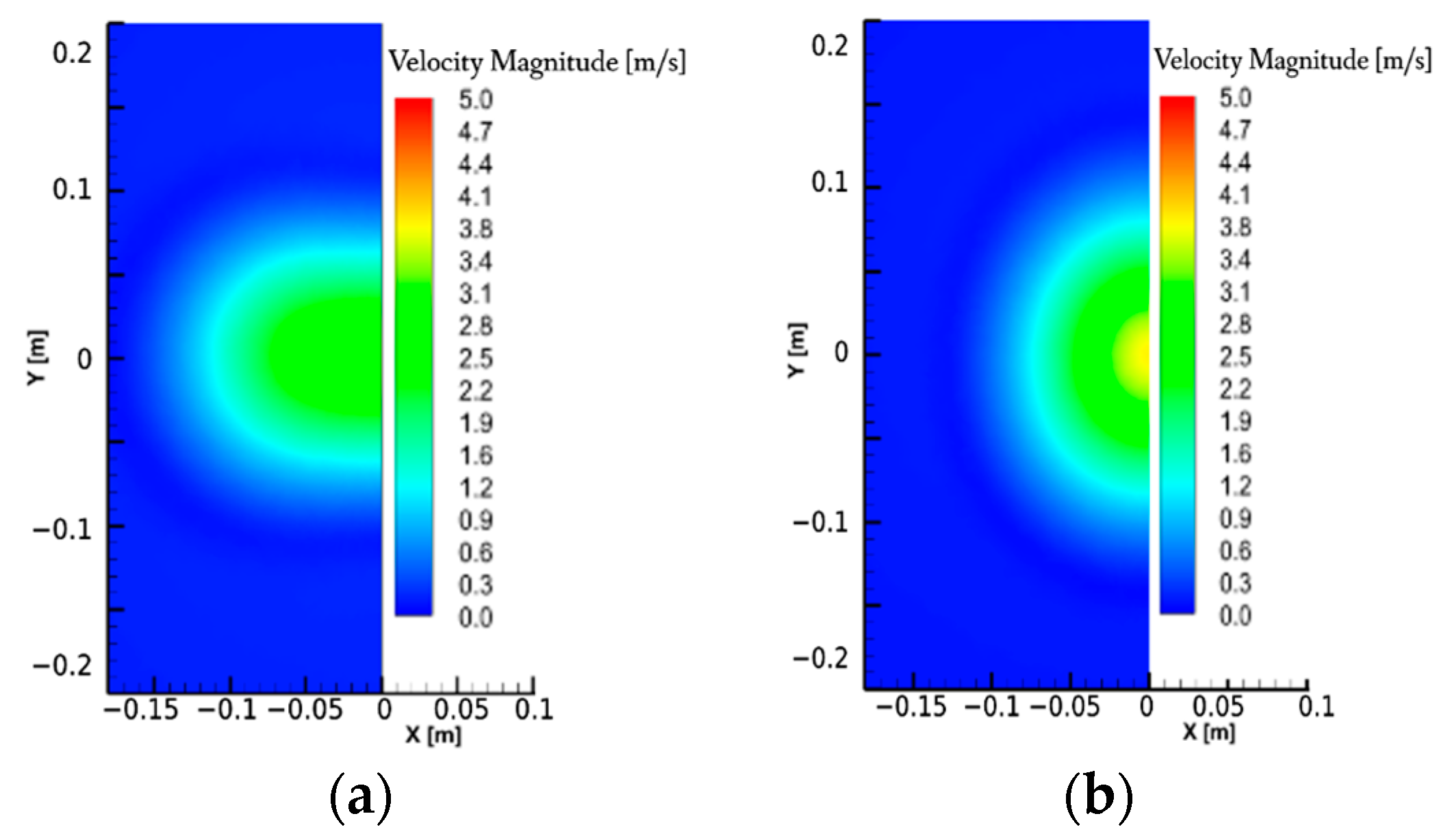
Figure 7 presents the velocity contours on a transversal plane positioned 100 mm away from the analyzed air diffusers. Figure 8 depicts the velocity contours on a transversal plane 600 mm from the tip of the air diffusers. The chosen length is near the driver’s face position within the vehicle, which is considered a relevant plan for investigating the velocity field.
Upon analyzing the velocity fields from Figure 7 and Figure 8, it becomes evident that the results demonstrate qualitative similarities. Notably, the standard air diffuser demonstrates the shortest potential core length. Additionally, jet expansion commences later for the standard air diffuser compared with the lobed air diffuser. Analyzing the transverse velocity field, noticeable differences in the jet shape can be observed at 600 mm among the studied air diffusers. Case V exhibits a broader spread compared to case A. This broader spread is desirable as it indicates a higher induction air diffuser, aligning with the intended objective of the work.

3.4. Entrainment Rate

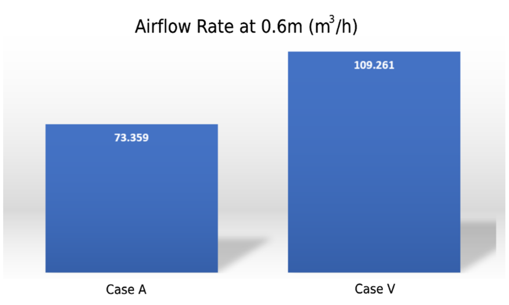
Tecplot 2021 software was used for the entrainment rate calculation at a distance of 600 mm from the dashboard (Figure 9). This specific distance was chosen because it corresponds to the average breathing zone distance from the dashboard for the occupants seated in the front seats of the Dacia/Renault Duster vehicle.
For the lobed air diffuser, there is an increase in the induction rate when juxtaposed with the standard air diffuser, particularly at a distance of 600 mm from the dashboard. Consequently, the entrained airflow for this novel air diffuser registers a substantial enhancement, precisely amounting to a 48% increase compared to the reference configuration. This substantial improvement underscores the efficacy of the case V air diffuser in optimizing airflow dynamics. For example, one can see that for a measured fresh airflow rate of 31.79 m3/h, the total air entrainment rate at 0.6 m for the standard air diffuser is 73.36 m3/h, while for the innovative air diffuser, it is 109.26 m3/h.
The results of this study suggest practical directions for the design of HVAC systems in vehicles, focusing on the potential to improve passenger comfort while maintaining energy efficiency. The enhanced air diffuser design, with its increased ambient air induction capabilities, demonstrates a method for improving thermal comfort that does not necessarily lead to higher energy consumption. Achieving a balance between the cooling and heating needs within a vehicle’s cabin by optimizing the blending of cool air from the HVAC system with the internal air can lead to a more even distribution of the temperature.
This approach reduces the extremes of cooling or heating that are often required. Moreover, the possibility of integrating high-induction air diffusers with other vehicle systems, such as adaptive climate controls that adjust based on real-time occupancy and external environmental conditions, offers a route to fine-tune the vehicle’s internal climate. This integration aims to create a more comfortable thermal environment for passengers while also supporting energy conservation efforts.

4. Conclusions

The comfort of vehicle occupants, particularly in thermal terms, is one of the essential parameters for a pleasant travel experience and safety. An uncomfortable thermal environment can lead to increased stress levels, potentially compromising the driver’s attention and reaction times. This situation elevates the risk of accidents. Moreover, improved thermal comfort for the driver can decrease fatigue, thereby enhancing concentration and reducing the likelihood of hazardous incidents.
One of the investigations carried out in this study was whether the high air exchange rates in vehicles, primarily driven by the need to manage thermal loads, contribute to better air quality or merely maintain thermal comfort. It highlights that the air change rates in vehicles are significantly higher than in buildings cases (12–18 times, reaching 48 to 144 ACH), emphasizing that the airflow in vehicles is more closely tied to thermal load removal rather than fresh air requirements. Consequently, even at the lowest ventilation settings, there is no concern for the accumulation of unhealthy compounds when air mixing is performed, as the primary function of this high airflow is thermal management.
High-induction air diffusers are, therefore, a promising solution for improving indoor air quality (IAQ) in vehicles. This study focused on improving the passive mixing of cooled air from the vehicle’s HVAC system with cabin air during summer conditions. The aim was to enhance the entrainment rate of airflow, minimizing the temperature gradient caused by the HVAC system’s output. This approach seeks to maintain occupant comfort while efficiently addressing the thermal load requirements.
Through numerical analyses, the performance of a novel air diffuser design was evaluated against the standard model installed in the Dacia/Renault Duster. The innovative lobed air diffuser demonstrated superior performance, achieving a 48% higher rate of ambient air entrainment in the occupants’ breathing zone than the conventional diffuser. This result indicates a significant improvement in the mixing of air within the vehicle cabin, directly impacting thermal comfort.
The implications of the research extend beyond the specific vehicle model studied, suggesting broad applicability across various vehicle types, including electric vehicles (EVs). The enhanced air mixing capability of the novel diffuser design could reduce the need for fresh air intake, potentially lowering HVAC system energy consumption. This reduction is particularly relevant for EVs, as it may contribute to increased vehicle autonomy by optimizing energy use, thus addressing a critical challenge in EV design without compromising interior comfort. This is a subject worth studying in the future.
By addressing thermal comfort optimization, this study offers a method for mitigating temperature disparities within a vehicle cabin. This improvement in air mixing not only promises to enhance occupant comfort but also supports safer driving conditions by reducing driver fatigue. Consequently, these findings contribute to the ongoing development of vehicle design and operation, aiming to improve the overall travel experience and safety, as well as the environmental impact of automotive HVAC systems. Additionally, the principles and innovations demonstrated in this research have potential applications in personalized ventilation systems, further enhancing indoor air quality and thermal comfort in various enclosed environments, such as office buildings.
Author Contributions

Conceptualization, F.I.B.; Methodology, F.I.B., G.M.S. and C.C.; Formal analysis, G.M.S. and I.N.; Investigation, F.I.B., T.O.J., P.D. and C.C.; Resources, F.I.B. and I.N.; Data curation, P.D.; Writing—original draft, F.I.B., I.N., T.O.J. and P.D. and C.C.; Supervision, F.I.B.; Funding acquisition, F.I.B. and I.N. writing—review and editing, F.I.B. and I.N. All authors have read and agreed to the published version of the manuscript.

Funding

This work was supported by a grant of the Ministry of Research, Innovation, and Digitization, CCCDI—UEFISCDI, project number PN-III-P2-2.1-PED-2021-0559, within PNCDI III,—Innovative high-induction air diffusers for improved indoor environmental quality in vehicles, and by a grant of the Ministry of Research, Innovation, and Digitization, CCCDI—UEFISCDI, project number PN-III-P2-2.1-PED-2021-2265, within PNCDI III,—Innovative seating system to reduce SARS-CoV-2 transmission on board of commercial aircrafts.

Data Availability Statement

Dataset available on request from the authors: The raw data supporting the conclusions of this article will be made available by the authors on request.

Conflicts of Interest

Author Titus Otniel Joldos was employed by the company Ruck Ventilatoare. The remaining authors declare that the research was conducted in the absence of any commercial or financial relationships that could be construed as a potential conflict of interest.

References

  1. Tsutsumi, H.; Hoda, Y.; Tanabe, S.-I.; Arishiro, A. Effect of Car Cabin Environment on Driver’s Comfort and Fatigue. SAE Trans. 2007, 116, 335–346. [Google Scholar]
  2. Csáky, I.; Kalmár, T.; Kalmár, F. Operation testing of an advanced personalized ventilation system. Energies 2019, 12, 1596. [Google Scholar] [CrossRef]
  3. Fanger, P.O. Thermal Comfort. Analysis and Applications in Environmental Engineering; Danish Technical Press: Copenhagen, Denmark, 1970. [Google Scholar]
  4. Kalmár, F.; Kalmár, T. Thermal comfort aspects of solar gains during the heating season. Energies 2020, 13, 1702. [Google Scholar] [CrossRef]
  5. Yang, B.; Liu, P.; Liu, Y.; Jin, D.; Wang, F. Assessment of thermal comfort and air quality of room conditions by impinging jet ventilation integrated with ductless personalized ventilation. Sustainability 2022, 14, 12526. [Google Scholar] [CrossRef]
  6. Wolkoff, P.; Azuma, K.; Carrer, P. Health, work performance, and risk of infection in office-like environments: The role of indoor temperature, air humidity, and ventilation. Int. J. Hyg. Environ. Health 2021, 233, 113709. [Google Scholar] [CrossRef] [PubMed]
  7. Ratajczak, K.; Amanowicz, Ł.; Pałaszyńska, K.; Pawlak, F.; Sinacka, J. Recent Achievements in Research on Thermal Comfort and Ventilation in the Aspect of Providing People with Appropriate Conditions in Different Types of Buildings—Semi-Systematic Review. Energies 2023, 16, 6254. [Google Scholar] [CrossRef]
  8. Orman, Ł.J.; Majewski, G.; Radek, N.; Pietraszek, J. Analysis of thermal comfort in intelligent and traditional buildings. Energies 2022, 15, 6522. [Google Scholar] [CrossRef]
  9. Alahmer, A.; Abdelhamid, M.; Omar, M. Design for thermal sensation and comfort states in vehicles cabins. Appl. Therm. Eng. 2012, 36, 126–140. [Google Scholar] [CrossRef]
  10. Sun, C.; Xu, S.; Yang, M.; Gong, X. Urban traffic regulation and air pollution: A case study of urban motor vehicle restriction policy. Energy Policy 2022, 163, 112819. [Google Scholar] [CrossRef]
  11. Chen, M.; Farahani, A.V.; Kilpeläinen, S.; Kosonen, R.; Younes, J.; Ghaddar, N.; Ghali, K.; Melikov, A.K. Thermal comfort chamber study of Nordic elderly people with local cooling devices in warm conditions. Build. Environ. 2023, 235, 110213. [Google Scholar] [CrossRef]
  12. Nastase, I.; Danca, P.; Bode, F.; Croitoru, C.; Fechete, L.; Sandu, M.; Coşoiu, C.I. A regard on the thermal comfort theories from the standpoint of Electric Vehicle design—Review and perspectives. Energy Rep. 2022, 8, 10501–10517. [Google Scholar] [CrossRef]
  13. Ming, R.; Li, B.; Du, C.; Yu, W.; Liu, H.; Kosonen, R.; Yao, R. A comprehensive understanding of adaptive thermal comfort in dynamic environments—An interaction matrix-based path analysis modeling framework. Energy Build. 2023, 284, 112834. [Google Scholar] [CrossRef]
  14. Wang, Z.; Wang, J.; He, Y.; Liu, Y.; Lin, B.; Hong, T. Dimension analysis of subjective thermal comfort metrics based on ASHRAE Global Thermal Comfort Database using machine learning. J. Build. Eng. 2020, 29, 101120. [Google Scholar] [CrossRef]
  15. Wang, X.; Yang, Q.; Zhai, Y.; Niu, H.; Wang, X. Effects of vehicle air temperature on drivers’ cognitive abilities based on EEG. Sustainability 2023, 15, 1673. [Google Scholar] [CrossRef]
  16. Boughanmi, N.; Frisch, J.; van Treeck, C. Evaluation of the airflow distribution of a vertical air ventilation system in a car cabin using PIV measurements and CFD simulations. Int. J. Heat Fluid Flow 2024, 107, 109411. [Google Scholar] [CrossRef]
  17. Wang, T.; Zhao, K.; Lu, Y.; Zhu, Y.; Shi, F.; Jiang, C.; Wang, Y.; Yang, B. The airflow characteristics and thermal comfort evaluation in high-speed train cabin with mixing ventilation: An experimental and numerical study. Build. Environ. 2024, 250, 111187. [Google Scholar] [CrossRef]
  18. Ogundiran, J.O.; Nyembwe, J.-P.K.B.; Ribeiro, A.S.N.; da Silva, M.G. A Field Survey on Indoor Climate in Land Transport Cabins of Buses and Trains. Atmosphere 2024, 15, 589. [Google Scholar] [CrossRef]
  19. Wang, F.; Chen, F.; Zhang, T.T. An aisle displacement ventilation system for twin-aisle commercial airliner cabin. Build. Environ. 2022, 223, 109439. [Google Scholar] [CrossRef]
  20. Wang, F.; You, R.; Zhang, T.; Chen, Q. Recent progress on studies of airborne infectious disease transmission, air quality, and thermal comfort in the airliner cabin air environment. Indoor Air 2022, 32, e13032. [Google Scholar] [CrossRef]
  21. das Neves Almeida, M.; de Paula Xavier, A.A.; Michaloski, A.O. A review of thermal comfort applied in bus cabin environments. Appl. Sci. 2020, 10, 8648. [Google Scholar] [CrossRef]
  22. Li, B.; Kuo, H.; Wang, X.; Chen, Y.; Wang, Y.; Gerada, D.; Worall, S.; Stone, I.; Yan, Y. Thermal management of electrified propulsion system for low-carbon vehicles. Automot. Innov. 2020, 3, 299–316. [Google Scholar] [CrossRef]
  23. Chang, T.-B.; Sheu, J.-J.; Huang, J.-W.; Lin, Y.-S.; Chang, C.-C. Development of a CFD model for simulating vehicle cabin indoor air quality. Transp. Res. Part D Transp. Environ. 2018, 62, 433–440. [Google Scholar] [CrossRef]
  24. Danca, P. Ventilation Strategies for Improving the Indoor Environment Quality in Vehicles; University of Rennes: Rennes, France, 2019. [Google Scholar]
  25. Markov, D.; Ivanov, N.; Pichurov, G.; Zasimova, M.; Stankov, P.; Smirnov, E.; Simova, I.; Ris, V.; Angelova, R.A.; Velichkova, R. On the Procedure of Draught Rate Assessment in Indoor Spaces. Appl. Sci. 2020, 10, 5036. [Google Scholar] [CrossRef]
  26. Feng, C.; Ma, F.; Wang, R.; Li, W.; Gao, J. A thermal comfort evaluation on vehicular environments based on local human body thermal sensations. Results Eng. 2023, 17, 100907. [Google Scholar] [CrossRef]
  27. Medaouar, W.; Loukarfi, L.; Braikia, M.; Khelil, A.; Naji, H. Experimental and numerical study of a turbulent multiple jets issued from lobed diffusers. J. Appl. Fluid Mech. 2019, 12, 729–742. [Google Scholar] [CrossRef]
  28. Bode, F.; Jamin, A.; Sirbu, G.M. Influence of the air diffusers on human thermal comfort inside vehicles—A review article. IOP Conf. Ser. Earth Environ. Sci. 2023, 1128, 012010. [Google Scholar] [CrossRef]
  29. Bragança, P.; Sodjavi, K.; Meslem, A.; Nastase, I. Passive control strategy for mixing ventilation in heating mode using lobed inserts. Energy Build. 2016, 133, 512–528. [Google Scholar] [CrossRef]
  30. Sekaran, A.; Amini, N. Vortex Dynamics and Instability Mechanisms in a Radially Lobed Nozzle. J. Fluids Eng. 2021, 143, 081102. [Google Scholar] [CrossRef]
  31. Balocco, C.; Lio, P. Assessing ventilation system performance in isolation rooms. Energy Build. 2011, 43, 246–252. [Google Scholar] [CrossRef]
  32. Bode, F.; Joldos, T.; Nastase, I.; Sirbu, G.M. Numerical study on high induction air diffusers for improved indoor environmental quality in vehicles. In Proceedings of the Indoor Air Quality, Ventilation and Energy Conservation in Buildings, IAQVEC 2023, Tokyo, Japan, 20–23 May 2023. [Google Scholar]
  33. Bode, F.; Joldos, T.; Sirbu, G.M.; Danca, P.; Nastase, I. Novel air diffuser with increased induction of ambient air for ventilation in vehicle. In Proceedings of the Sustainable Development in Building and Environment Conference (SUDBE 2023), Espoo, Finland, 14–18 August 2023. [Google Scholar]
  34. Bode, F.; Nastase, I.; Danca, P. Enhancing air mixing through air diffusers for ventilation in vehicles and enclosed spaces. In Proceedings of the 2024 10th International Conference on Environment and Renewable Energy, Nha Trang, Vietnam, 25–27 February 2024. [Google Scholar]
  35. Nastase, I.; Meslem, A. Vortex dynamics and mass entrainment in turbulent lobed jets with and without lobe deflection angles. Exp. Fluids 2010, 48, 693–714. [Google Scholar] [CrossRef]
  36. Jahanbin, A.; Semprini, G. Integrated effects of the heat recovery ventilation and heat source on decay rate of indoor airborne particles: A comparative study. J. Build. Eng. 2022, 50, 104156. [Google Scholar] [CrossRef]
  37. Chen, H.; Zhou, X.; Feng, Z.; Cao, S.-J. Application of polyhedral meshing strategy in indoor environment simulation: Model accuracy and computing time. Indoor Built Environ. 2022, 31, 719–731. [Google Scholar] [CrossRef]
  38. Qin, C.; Lu, W.-Z. Effects of ceiling exhaust location on thermal comfort and age of air in room under impinging jet supply scheme. J. Build. Eng. 2021, 35, 101966. [Google Scholar] [CrossRef]
  39. Ansys. Ansys Fluent Theory Guide; ANSYS, Inc.: Canonsburg, PA, USA, 2019. [Google Scholar]
  40. Goudarzi, N.; Sheikhshahrokhdehkordi, M.; Khalesi, J.; Hosseiniirani, S. Airflow and thermal comfort evaluation of a room with different outlet opening sizes and elevations ventilated by a two-sided wind catcher. J. Build. Eng. 2021, 37, 102112. [Google Scholar] [CrossRef]
  41. Hubbard, J.A.; Cheng, M.-D.; Domino, S.P. Mixing in Low Reynolds Number Reacting Impinging Jets in Crossflow. J. Fluids Eng. 2023, 145, 051303. [Google Scholar] [CrossRef]
  42. Raphe, P.; Denaclara, J.-Y.; Dghim, M.; Lateb, M.; Fellouah, H.; Ameur, M. A mixed numerical-experimental study of the outdoor wind effects on the indoor air distribution under the multi-nozzle air curtains. J. Build. Eng. 2023, 77, 107433. [Google Scholar] [CrossRef]
  43. Teodosiu, C.; Ilie, V.; Teodosiu, R. Appropriate CFD turbulence model for improving indoor air quality of ventilated spaces. Model. Civ. Environ. Eng. 2014, 10, 28–42. [Google Scholar] [CrossRef]
  44. Ivanov, N.; Zasimova, M.; Stepasheva, E.; Kudryavtseva, V. CFD modeling of a self-oscillatory airflow regime in the test ventilated room with plane supply opening. E3S Web Conf. 2022, 356, 04020. [Google Scholar] [CrossRef]
  45. Hurnik, M.; Ivanov, N.; Zasimova, M.; Popiolek, Z. Local and gross parameters of air distribution in a room with a sidewall jet: CFD validation based on benchmark test. Build. Environ. 2022, 207, 108509. [Google Scholar] [CrossRef]
  46. Boutier, A. L’ensemencement en Vélocimétrie Laser; AFVL Ecole d’Automne, Vélocimétrie et Granulométrie Laser: St-Pierre d’Oléron, France, 2003. [Google Scholar]
Figure 1. (a) Central part of the Dacia/Renault Duster dashboard; (b) central air diffuser.
Energies 17 02930 g001
Figure 2. Analyzed air diffusers. (a,b) Case A: different views; (c,d) case X: different views.
Energies 17 02930 g002
Figure 3. (a) LDV measurement experiment sketch-up; (b) image with the experimental setup.
Energies 17 02930 g003
Figure 4. LDV measurement; (a) reference air diffuser; (b) lobed air diffuser.
Energies 17 02930 g004
Figure 5. LDV measurement comparison with the CFD results; (a) reference air diffuser; (b) lobed air diffuser.
Energies 17 02930 g005
Figure 6. Velocity contours for the flow from the air diffusers (longitudinal section); (a) standard case; (b) lobed air diffuser.
Energies 17 02930 g006
Figure 7. Velocity contours in a transversal section situated 100 mm away from the tip of the (a) standard air diffuser and (b) lobed air diffuser.
Energies 17 02930 g007
Figure 8. Velocity contours in a transversal section situated 600 mm away from the tip of the (a) standard air diffuser and (b) lobed air diffuser.
Energies 17 02930 g008
Figure 9. Induction rates for the studied air diffusers at 600 mm from the dashboard.
Energies 17 02930 g009
Table 1. Airflow rates through the dashboard air diffusers for the 2nd speed of the HVAC fan.
Air DiffuserAreaMean VelocityFlow RateFlow RateFlow RateDistribution
m2m/sm3/skg/sm3/h%
LD0.0023474.1760.0098010.01200635.2821.50%
CLD0.0024293.5650.008660.01060931.1819.00%
CD0.0024174.1310.0099830.01222935.9421.90%
CRD0.0023213.3520.0077810.00953228.0117.07%
RD0.002363.9630.0093530.01145733.6720.52%
Total0.0455780.055833164.08
Disclaimer/Publisher’s Note: The statements, opinions and data contained in all publications are solely those of the individual author(s) and contributor(s) and not of MDPI and/or the editor(s). MDPI and/or the editor(s) disclaim responsibility for any injury to people or property resulting from any ideas, methods, instructions or products referred to in the content.