1. Introduction
The heat flux of high-power electronic components, such as IGBT, exhibits a significant increase with integrated design [
1], thereby exacerbating the issue of heat dissipation. Research has indicated that exceeding the manufacturer’s specified operating temperature limit for electronic components can lead to substantial degradation in product performance and reliability [
2].
Finned radiators are widely used in thermal management due to their simple structure and high efficiency [
3,
4,
5,
6,
7]. However, traditional finned radiators have high thermal diffusion resistance. As the size of heating components decreases, heat flux increases and the influence becomes more prominent [
8]. The use of phase change materials (PCMs) [
9] and heat pipes can effectively improve the performance of radiators. Phase change heat dissipation technology can effectively absorb or release heat through the change of the physical state of phase change materials, so as to achieve passive thermal management. A heat pipe is an efficient heat transfer device based on the principle of vapor–liquid phase change, which requires no external power and only relies on repeated phase transformation of the internal working medium to achieve rapid heat transfer. It is usually composed of a tube shell and a liquid suction core. Flat heat pipes (FHPs) or vapor chambers (VCs) have been widely used in the thermal management of electronic devices [
10,
11]. The combination of a heat pipe and fins is one of the common heat dissipation methods of electronic components.
The working principle of a VC is similar to that of a heat pipe. It is composed of a sealed cavity with a vacuum inside. The inner surface of a VC is usually covered with a porous liquid suction core structure [
12,
13]. A VC is one of the phase change heat transfer devices that has attracted much attention at present, and it has been used to cool electronic devices in combination with finned radiators [
14,
15]. Li et al. [
16] have proposed an ultra-large aluminum-based flat heat pipe to solve the heat dissipation problem of high-power communication equipment. Under the conditions of natural air cooling and vertical placement, the heat dissipation module can effectively manage 150 W of input power with the junction temperature close to 80 °C, which is about 20 °C lower than with a traditional aluminum-based fin heat dissipation module of the same size. Rezk et al. [
17] designed an integrated vapor chamber–straight fins (VCSF) heat sink using the bottom of the fin as the condensing end, and the results showed that VCSF’s reduction of the temperature of electronic components under all operating conditions compares to that of SFs. Berut et al. [
18] manufactured and tested a vapor chamber with integrated hollow fins, determining a triangle as the optimal fin geometry to prevent liquid hold-up and flooding on the condensing end. Ji et al. [
19] designed an integrated flat heat pipe (IFHP) that consists of an evaporator and a condenser with multiple channels fabricated in the fin heat sink and compared it with a conventional flat heat pipe (CFHP). The results showed that IFHP eliminates the contact heat set between heat pipes and heat sinks, expands the condensation area and reduces the temperature difference between the base and the end of the heat sink.
Although the use of a VC as a radiator base can greatly improve the performance of the radiator, its manufacturing process is more complex, and the cost is high. A lower-cost solution is the use of heat pipe-embedded heat sinks (HPeH) that, when properly designed, perform similarly to heat sinks with flat heat pipes, which can effectively reduce the thermal resistance of diffusion while having the advantages of low cost and simple process. Song et al. [
20] embedded a heat pipe into the bottom plate of a traditional radiator, and the maximum temperature of a heat source was reduced by 15 °C compared to that of a conventional radiator. Wang et al. [
21] studied the cooling performance of a heat pipe embedded in the bottom of a radiator with different arrangement and its influence on the temperature distribution of a CPU. The minimum thermal resistance of the heat pipe-embedded radiator studied was 0.15 °C/W, lower than the 0.22 °C/W of the reference conventional radiator. The overall performance of the H-type embedded radiator was also the best, with heat dissipation increased by 22.5%. At the same time, the weight was reduced by 30.1%, and the simulation showed that the use of a heat pipe-embedded radiator instead of a traditional radiator could reduce the power consumption of the fan by 66.2%.
Without changing the fin radiator structure, and further using phase change technology to strengthen the performance of the radiator, there is a solution to use flat heat pipes as fins to replace conventional aluminum fins. A kind of flat heat pipe called the roll-bond flat heat pipe (RBFHP), whose technology is used in refrigerator evaporators, is made of two aluminum plates through runner printing, rolling, expansion, liquid injection and liquid injection pipe welding [
22], with low manufacturing cost, high reliability, and easy-to-obtain large area. Its thickness can be 1–5 mm. However, similar to the thermosiphon [
23], there is no liquid suction core structure inside a RBFHP, and gravity has a great influence on it. Deng et al. [
22] studied the thermal performance of RBFHPs with three typical structures (staggered, crossed and aligned) and four filling ratios (5%, 10%, 20% and 40%). The results showed that the internal boiling state was determined by the filling ratio and heating power, and the RBFHP with a staggered filling rate of 20% had the best performance. They [
24] also conducted tests under the condition of multi-heat source natural convection, and the research shows that compared with the uniformly heated aluminum plate under a total heat load of 48 W, the total thermal resistance and temperature rise could be reduced by 15.3% and 10 °C, respectively. RBFHPs have excellent thermal performance, but it is rare to study it as a fin on the whole radiator system, and the comparison with conventional aluminum-fin radiators needs to be studied.
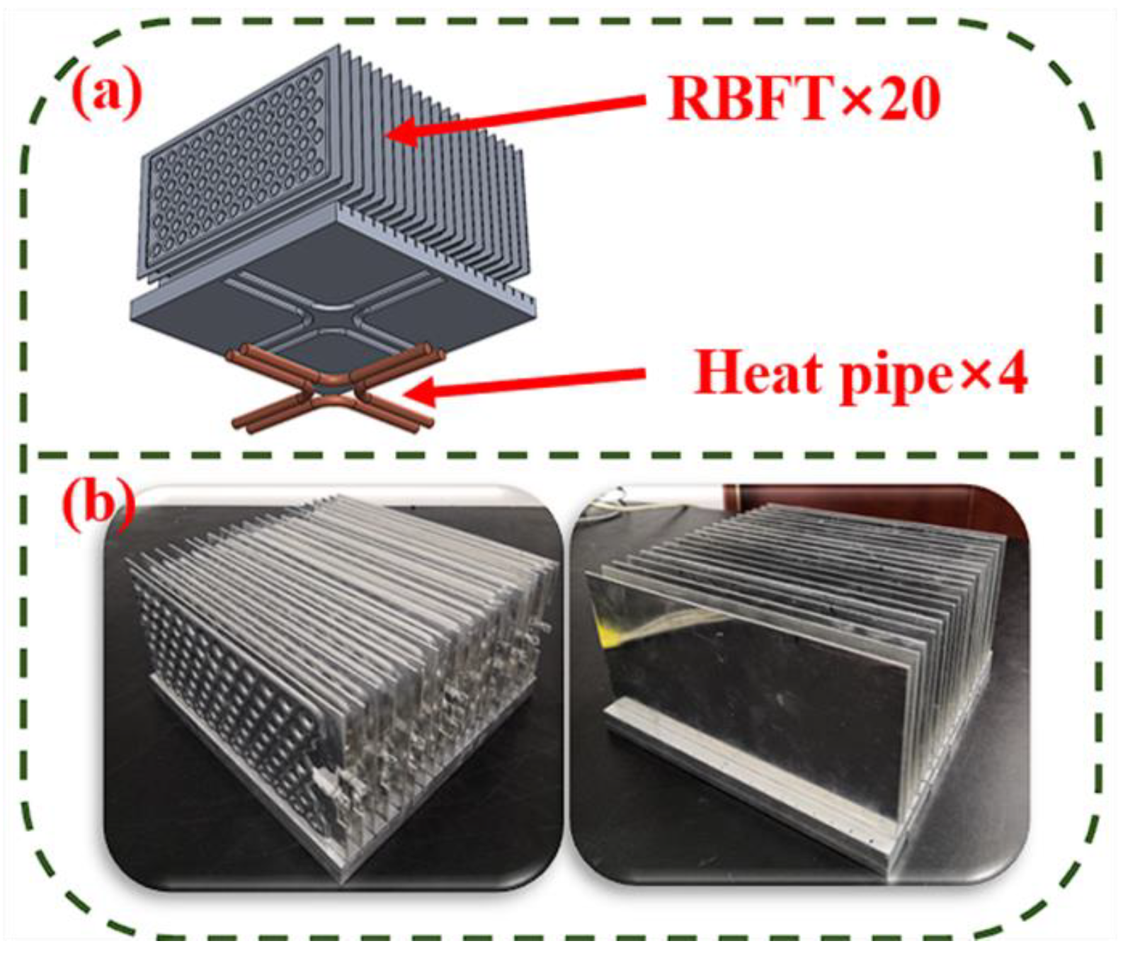
In this context, a comprehensive experimental study on the performance of a HPs-RBFHPs composite radiator designed for the cooling of high-power electronic devices was carried out. Phase change devices were introduced into the fin and base at the same time to strengthen the heat transfer capacity of the radiator. The heat transfer characteristics of the radiator were evaluated under a series of experimental conditions, and the factors affecting the performance of the radiator were revealed through careful comparison and analysis.
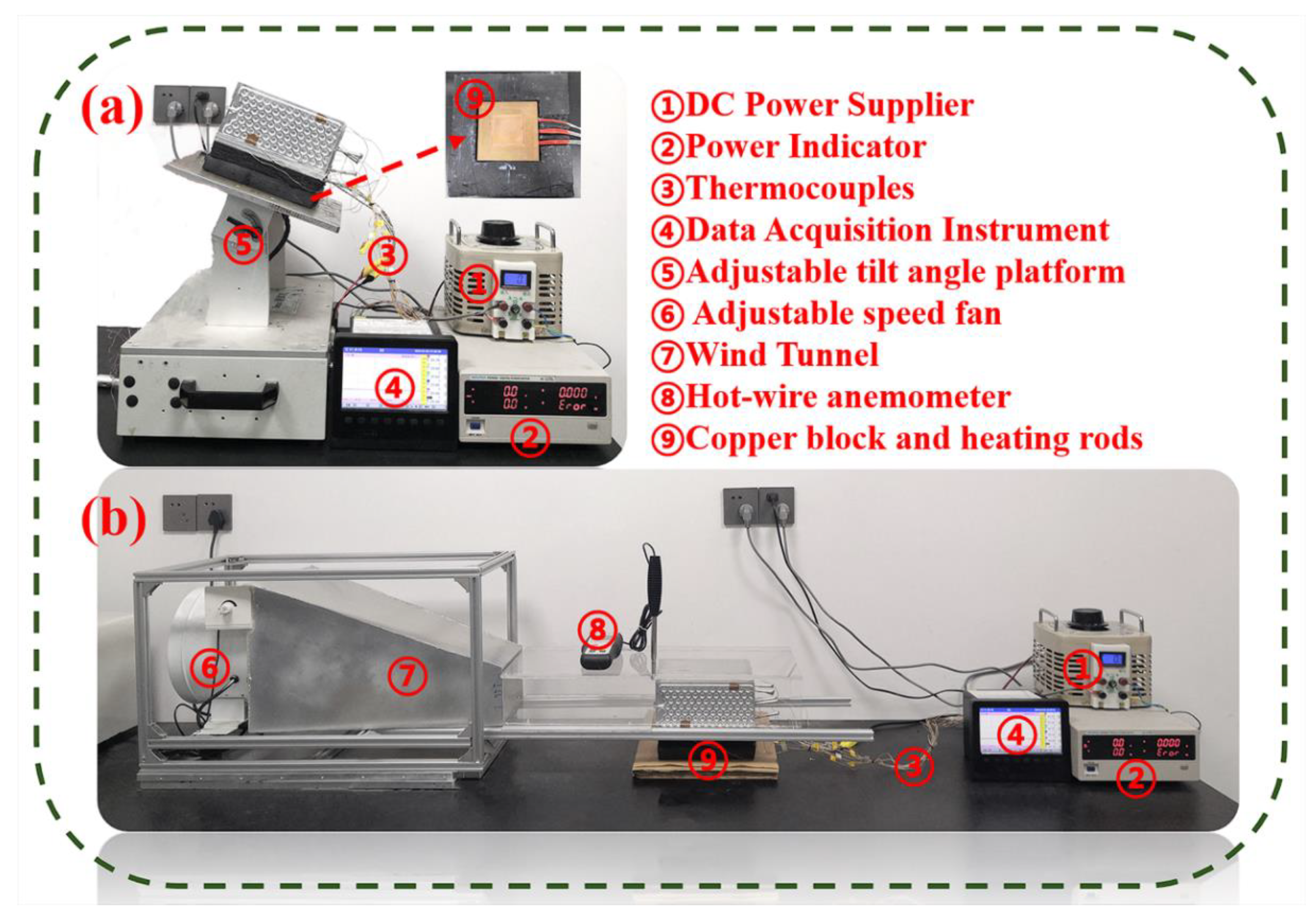
In subsequent sections, the experimental setup is described in detail (
Section 2), the heat transfer characteristics of the radiator under various heating powers, inclination angles [
25] and wind speeds are shown in comparison (
Section 3), and the significance of future research is highlighted by summarizing the key conclusions (
Section 4), which provide a reference for promoting the application of heat pipe radiators in high-power electronic devices.
3. Results and Discussion
By using HPs-RBFHPs to cool high-power electronic components and equipment, several experiments were conducted to study the effects of different heat fluxes, different system gravity directions (0° to 90°) and different wind speeds (0 m/s to 4 m/s) on the whole system under forced convective heat transfer. The performance of an SF radiator was compared.
3.1. Radiator Performance in Horizontal State
In HPs-RBFHPs, heat transfer is a complex interplay of multiple processes that mutually influence each other. The heated copper block simultaneously conducts heat to both the aluminum base and the heat pipes, which in turn facilitate the transfer of heat to the remote end, effectively spreading it laterally across a flat surface. Subsequently, longitudinal heat conduction through the aluminum base enables thermal energy to be transferred to the RBFHPs. With gravity aiding its operation, passive phase transition cycles involving evaporation–boiling–condensing reflux occur within the 2-dimensional aeration loop of the RBFHP, resulting in efficient flattening of heat distribution within its fins. By analyzing temperature response patterns, one can gain insights into the thermal characteristics exhibited by this composite radiator.
As depicted in
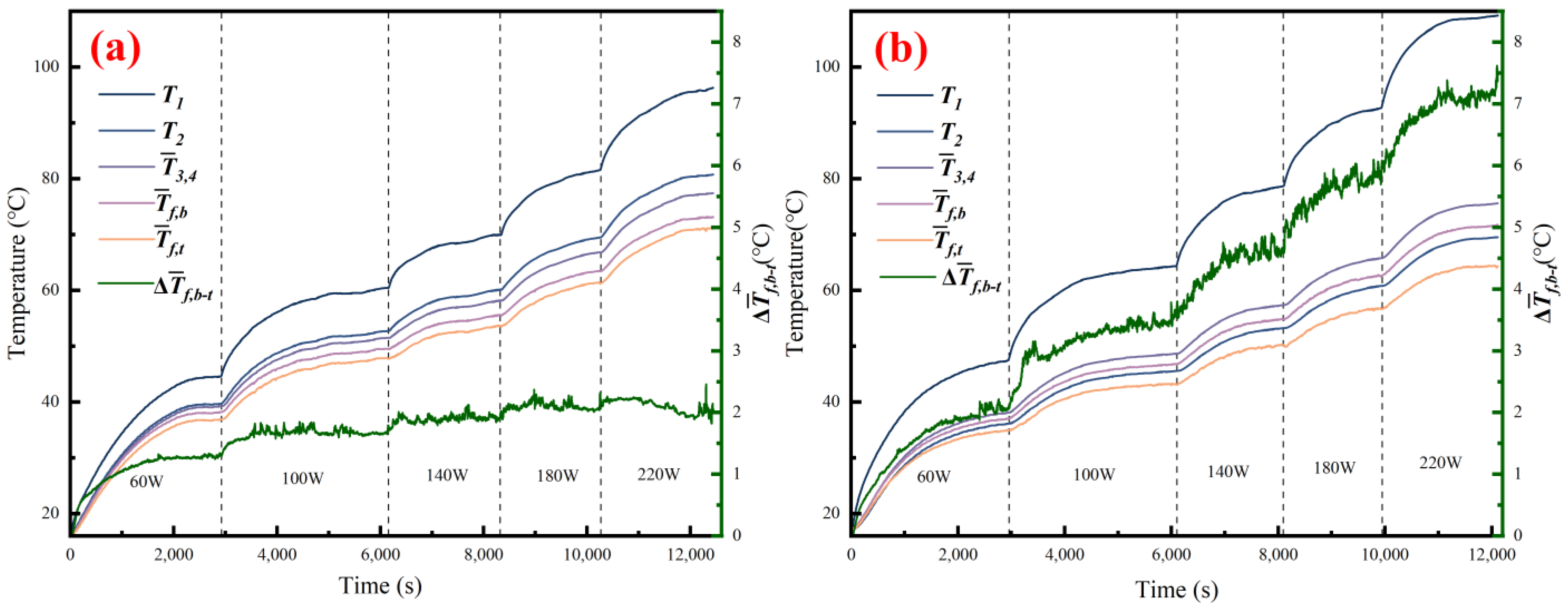
Figure 5, overall temperature variations observed in different parts of both radiators exhibited similar trends and generally showed an incremental rise with increasing heat flux levels. Under identical heating power conditions, over time, temperature curves experienced significant initial climbs followed by gradual stabilization tendencies. Notably, contrasting SFs performance-wise, HPs-RBFHPs demonstrated significantly smaller temperature differences among their respective components, indicative of superior temperature equalization capabilities.
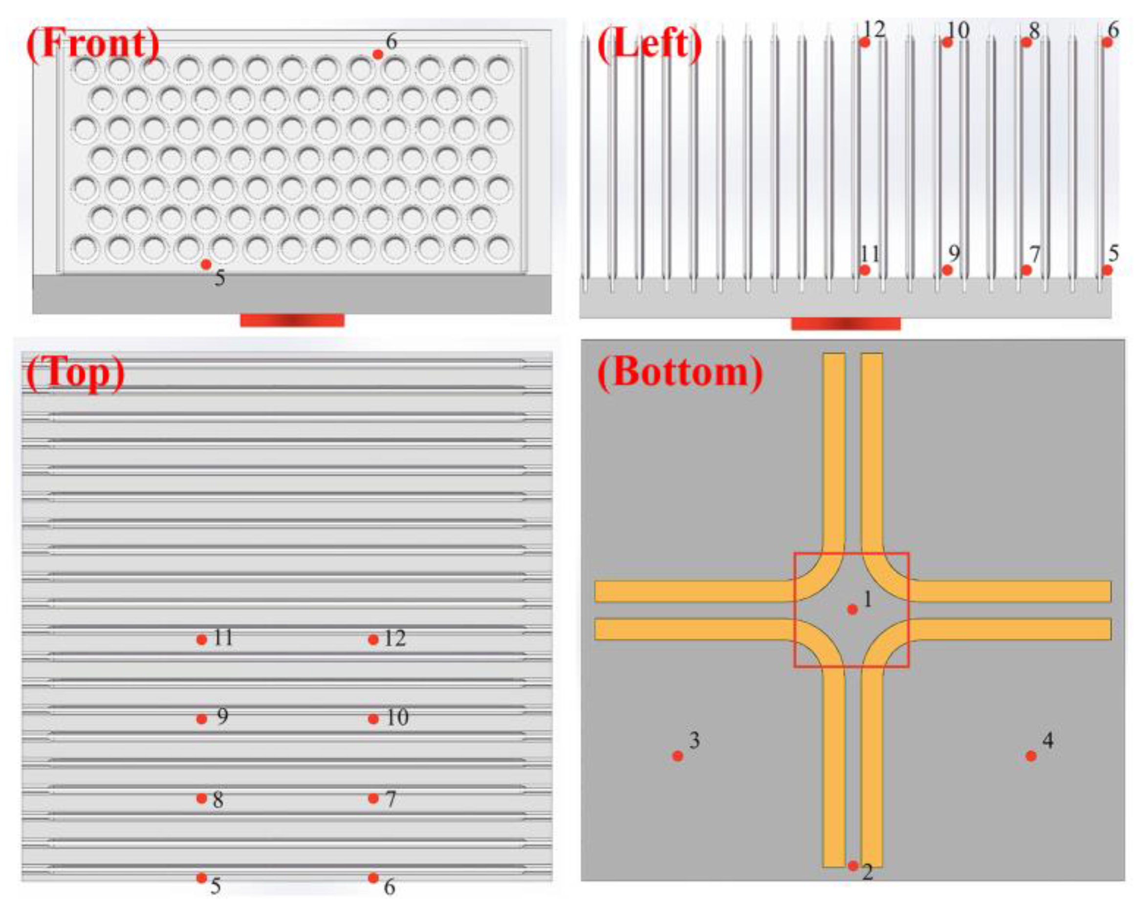
Due to the heat pipe embedded at the bottom, the T2 point was at the far end, but due to the role of the base-embedded heat pipe, its temperature was the highest with the exception of T1 (heat source temperature). It can be considered that the heat of the composite radiator diffuses in a cross-like plane at the bottom of the base. SF mainly relies on heat conduction, the heat diffuses from the center to the four sides on the base. Its temperature equalization was poor, which led to the lowest T2 temperature measured at the base and the largest temperature difference with the heat source. Specifically, at 220 W stability, the temperature difference between T1 and T2 reached 39.7 °C, while with the composite heat pipe radiator it was only 15.5 °C, which was only 39% that of SFs.
Δ
Tf,b−t is the difference between the average temperature of the fin bottom and the top of the fin, which is used to observe the average temperature of the whole fin.
Figure 5 shows that Δ
Tf,b−t changes of the two radiators had great differences, and with the increase of heat flux, the difference in fin temperature average became more and more obvious. The Δ
Tf,b−t of SF basically showed a step-up trend with the increase of heating power. At 220 W, the Δ
Tf,b−t of SF reached about 7 °C, while with HPs-RBFHPs it was only about 2 °C. When starting from 60 W heating power, the Δ
Tf,b−t of the two radiators showed a trend of rapid rise first and then stability. The temperature difference between the upper and lower ends of the fins of HPs-RBFHPs was 1.5 °C, while that of SF was 2 °C. Under the heat flux of 60 W, it can be considered that the RBTHP group did not start. The main reason for this slight difference was the difference in the average temperature of the base, and the secondary reason was the difference in the surface morphology of RBTHPS and the conventional aluminum fins. When
P ≥ 100 W, the Δ
Tf,b−t of HPs-RBFHPs basically fluctuated at about 2 °C, at which time it can be considered that the RBTHP group was fully activated.
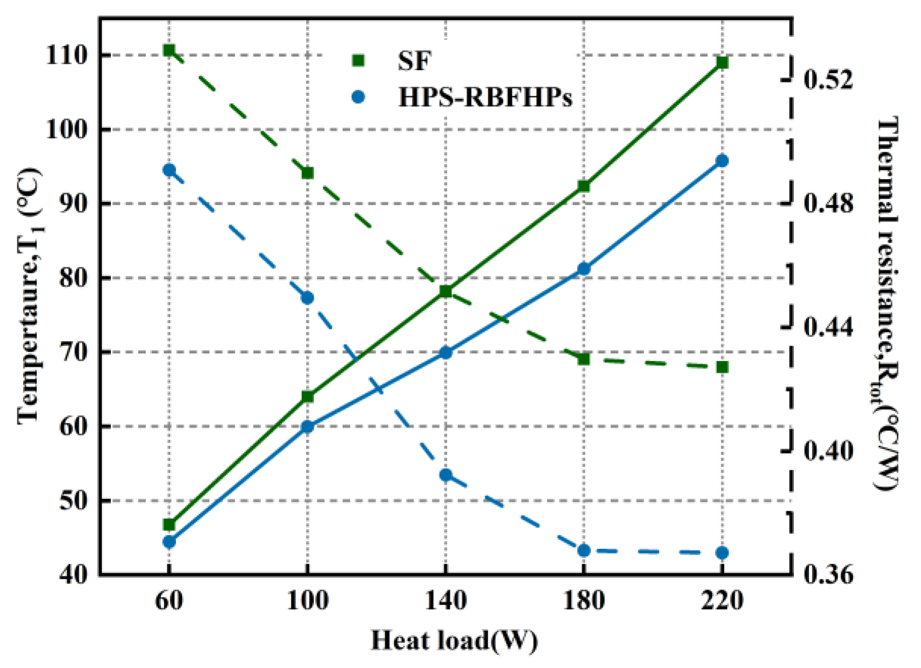
The solid line in
Figure 6 shows the comparison of heat source temperatures between HPs-RBFHPs and SF under variable power conditions. From a safety point of view, the junction temperature of electronic devices at work usually cannot exceed 85 °C. The results show that the maximum cooling power of HPs-RBFHPs (about 190 W) was 18.75% higher than that of SF (about 160 W) when the heat source temperature was 85 °C. The dashed line in
Figure 6 shows the change of the total thermal resistance of the composite heat pipe radiator and SF under different heating power. With the increase of heating power, the overall variation trend of the total thermal resistance decreased first and then became stable. HPs-RBFHPs had the highest slope in the heating power range of 100 to 140 W because the fin group was fully activated in this power range, reducing the thermal resistance at the fin end. From 140 W onwards, the total thermal resistance of the two radiators began to decrease slowly. After 180 W, the total thermal resistance of the two radiators hardly changed. When the heating power increased from 60 to 220 W, the total thermal resistance of HPs-RBFHPs decreased from 0.49 to 0.37 °C/W, a reduction of 24%. The total thermal resistance of SF was reduced from 0.53 to 0.43 °C/W, a reduction of 19%. When the heating power reached 180 W, the difference between the total resistance of HPs-RBFHPs and that of SF was the largest, and the total thermal resistance of HPs-RBFHPs at this power was 16.3% lower than that of SFs.
3.2. The Effect of Different Gravity Directions on the System
In practical application, especially in electronic components that need to work in special conditions, such as navigation, aviation, photovoltaic systems, etc., electronic equipment needs to operate under inclined conditions. Therefore, several sets of experiments were designed to study the effects of different gravity directions on the system’s performance at intervals of 30° from 0° to 90°.
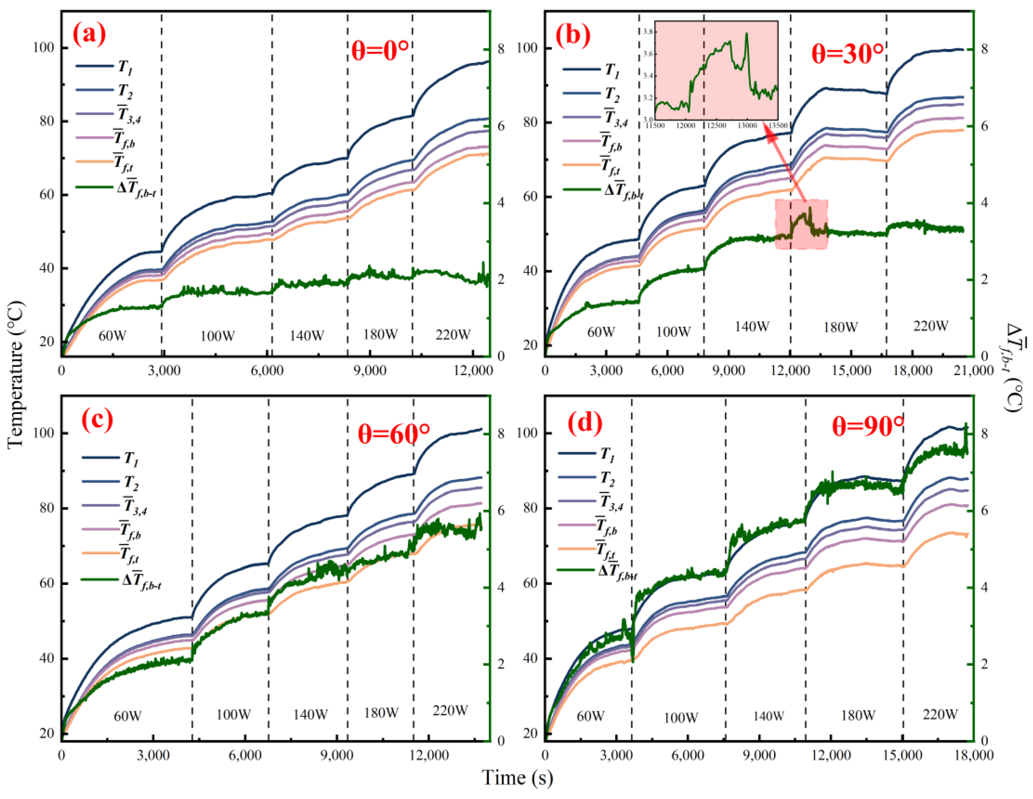
Figure 7 shows the startup process of each part of HPs-RBFHPs at angles of 0°, 30°, 60° and 90°.
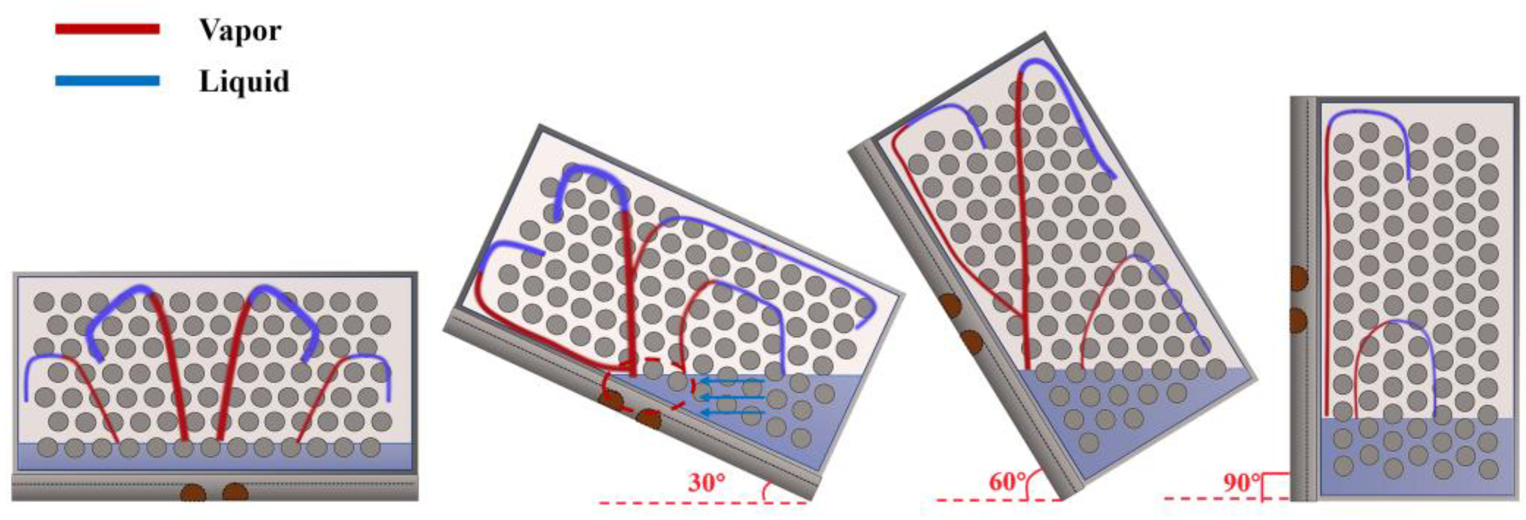
Figure 8 depicts the distribution of the working fluid inside the blown plate under different angles of gravity action and the internal flow diagram based on a reasonable assumption of the heat source. Due to the role of the heat pipe on the base,
T2 still maintained a high temperature and the heat pipe had a strong anti-gravity performance. It can be considered that the change of inclination angle had little influence on the temperature average of the heat pipe composite base.
Δ
Tf,b−t is the difference between the average temperature of the rib base and the top of the rib that can be used to evaluate the operation of the blown fin. As shown in
Figure 7a, when the heat flux was 100 W at 0°, Δ
Tf,b−t reached a stable state, around 2 °C. As shown in
Figure 7b, when the inclination was 30°, a step change was shown from 60 to 140 W, and a peak appeared at 180 W, with an evolution time of about 250 s. This was because, as shown in
Figure 8, when the inclination was 30°, the edge of the liquid pool of RBFHP was close to the heat pipe in the center, and the heat load was insufficient at low heat flux. At 180 W, nuclear boiling took away a lot of heat, and the heat flux was basically the same from 180 W to 220 W. The results show that the blown plate group could activate normally at 30
°inclination, but the heat flux required by Δ
Tf,b−t was 40 W higher than that required in the horizontal state. As shown in
Figure 7c, when the inclination was 60°, Δ
Tf,b−t basically presented a step trend, but when the heat flux was greater than 140 W, Δ
Tf,b−t had a large disturbance but the upward trend slowed down because the liquid pool could not operate stably due to constant heat flow. As shown in
Figure 7d, when the inclination was 90°, Δ
Tf,b−t showed basically the same performance as SF did under the horizontal state (
Figure 5b). It can be considered that the inflating sheet group was not activated, and the temperature difference of the heat source was 8 °C when the temperature of the heat source was stable at 220 W, which was mainly caused by the temperature uniformity of the base.
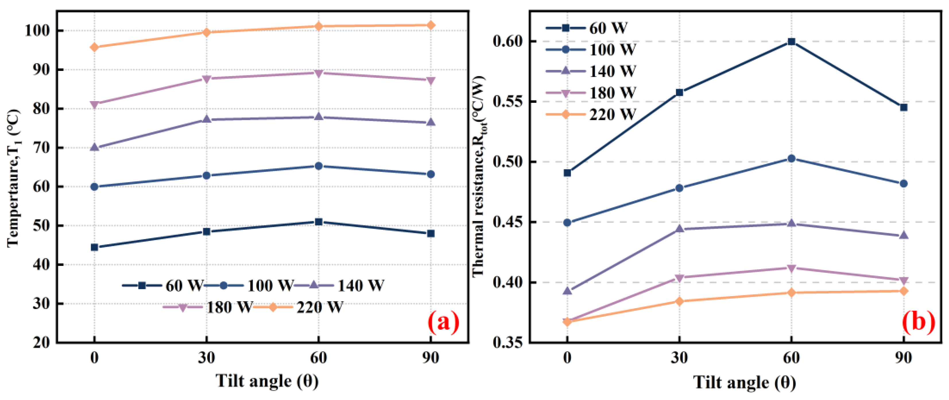
Figure 9a reflects the relationship between the temperature of the heat source and the inclination angle under different powers. The temperature of the heat source did not change greatly with the increase of the inclination angle. In the horizontal state, HPs-RBFHPs had good performance. It can be seen from
Figure 9b that the thermal resistance of the system was the highest at a lower power angle of 60°, but the thermal resistance decreased the most with the increase in power from 0.6 to 0.39 °C/W. At the same time, the thermal resistance in the horizontal state, which was only 0.12 °C/W, changed the least with power. In addition to the horizontal working state, the
T1 difference under the other three angles could be almost ignored, and it can be considered that the
T1 difference of the heat pipe radiator and SF under angled working conditions was mainly due to the temperature uniformity of the base. It can be concluded that the temperature uniformity of the base had the greatest effect on the heat source temperature in the case of large dip angles.
3.3. Effect of Forced Convection Heat Transfer on the System
The thermal characteristics of HPs-RBFHPs under forced convection conditions were investigated by comparing them with those of SF. Wind speed options included 1, 2, 3 and 4 m/s.
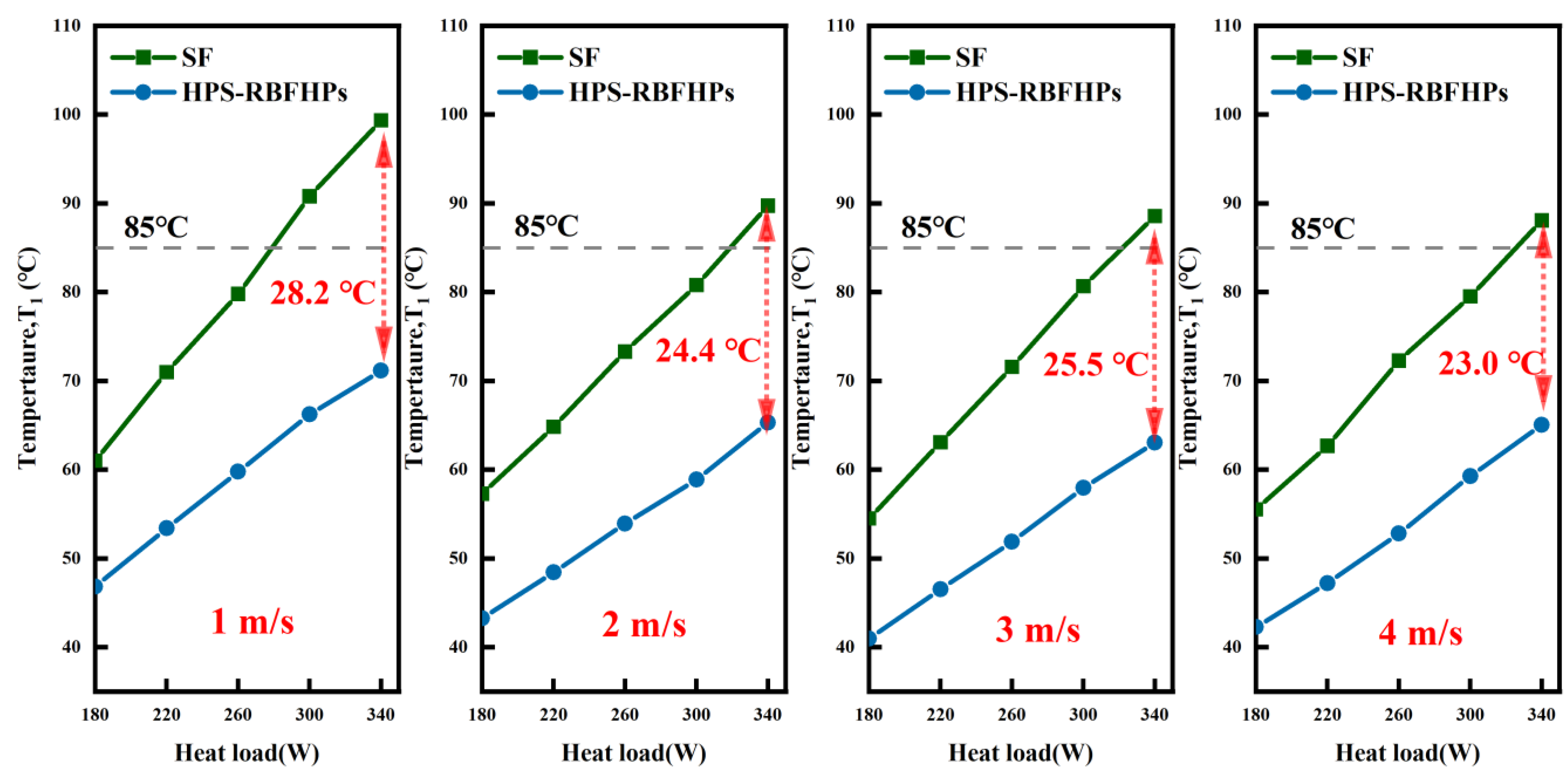
Figure 10 illustrates the comparison of heat source temperature between HPs-RBFHPs and SFs at different wind speeds and power levels. When subjected to a maximum heat load of 340 W in a forced convection environment, the heat source temperature of HPs-RBFHPs remained below the junction temperature threshold of 85 °C. Furthermore, an inverse relationship was observed between the heat source temperature of HPs-RBFHPs and wind speed; significant reduction in heat source temperature occurred when wind speed increased from 1 to 2 m/s. However, once the wind speed reached or exceeded 2 m/s, there was minimal change in the heat source temperature due to incomplete fin passage at lower speeds causing greater influence among fins. Additionally, at a wind speed of 1 m/s, there existed a maximum temperature difference of approximately 28.2 °C between two radiators and their respective heat sources; however, this difference decreased to a range between 23.0 and 25.5 °C after reaching a wind speed above or equal to 2 m/s with little variation thereafter. The increase in wind speed further contributed to reducing the heat source’s temperature; nevertheless, the impact on its overall performance became negligible beyond wind speeds exceeding 2 m/s as diffusion thermal resistance within the radiator base emerges as its primary limiting factor.
The parameter ΔTf,b−t represents the temperature difference between the average temperature at the base and top of the rib, which serves as an indicator for evaluating the overall performance of the blown fin group. STDEV.P refers to the standard deviation of average temperatures measured across four groups of fins, providing a measure for assessing temperature dispersion among fins. STDEV.P is primarily influenced by two factors: firstly, variations in base temperature equalization leading to differential heat conduction among individual fins; secondly, mutual interactions between fins with greater impact observed closer to the center of the radiator. Increasing wind speed effectively mitigates this effect. These two sets of data collectively evaluate radiator performance, with smaller values indicating better performance.
Figure 11 and
Figure 12 illustrate changes Δ
Tf,b−t and
STDEV.P over time under variable power conditions. With increasing heat flux, there was a stepwise increase trend observed in
STDEV.P; however, compared to SFs (standard fins), HPs-RBFHPs (heat pipe-embedded radial basis function heat pipes) exhibited approximately 70% lower
STDEV.P due to superior embedded temperature equalization on its base plate compared to that of SFs. As wind speed increased, there was a general decreasing trend observed in
STDEV.P parameters along with weakened influence from fin interactions. When wind speed increased from 1 to 2 m/s, both HPs-RBFHPs and SFs experience significant decreases in
STDEV.P—HPs-RBFHPs’ decreased by 45%, while SFs’ decreased by 34%. This further confirmed that at a wind speed of 1 m/s, airflow could not fully penetrate through the fin group, resulting in substantial impact on internal fins from both sides. When wind speed exceeded 2 m/s, although reductions in
STDEV.P became less pronounced between these two cases, increased wind velocity still effectively enhanced uniformity in average temperatures among the fins.
Figure 11 shows that the Δ
Tf,b−t of HPs-RBFHPs stabilized in a range under relatively high power, similar to that under natural convection. When stable, it could be considered that the blown fin group was fully activated. However, as wind speed increased, the heat flux required to stabilize within a range increased. For example, at a wind speed of 1 m/s, Δ
Tf,b−t stability required 140 W, and at a wind speed of 3 m/s, it required 220 W. In the case of high power, the Δ
Tf,b−t of HPs-RBFHPs was basically stable between 1.5 and 2 °C, which reflected the good temperature equating performance of the fin group. The Δ
Tf,b−t of SFs showed a step-up trend with the increase of heat flux, and the effect of wind speed was not significant, but with the increase of wind speed, it showed a change of decreasing first and then increasing. At low wind speed, the average temperature of the fin group could be improved, but because the heat was not transmitted to the upper end of the fin when the wind speed increased, it led to Δ
Tf,b−t increasing. The stability of the two systems was better with wind speed increases, which is reflected in
Figure 11 and
Figure 12. The greater the wind speed, the smaller the fluctuation and the smoother the curve.

