Article

Analysis of Ferroresonance Mitigation Effectiveness in Auxiliary Power Systems of High-Voltage Substations

1
Department of Electrical Engineering and Power Engineering, Faculty of Electrical Engineering, Automatics, Computer Science and Biomedical Engineering, AGH University of Krakow, al. A. Mickiewicza 30, 30-059 Krakow, Poland
2
Faculty of Electrical and Control Engineering, Gdansk University of Technology, Narutowicza 11/12, 80-233 Gdansk, Poland
*
Author to whom correspondence should be addressed.
Energies 2024, 17(10), 2423; https://doi.org/10.3390/en17102423
Submission received: 19 March 2024 / Revised: 4 May 2024 / Accepted: 14 May 2024 / Published: 18 May 2024
(This article belongs to the Section F1: Electrical Power System)

Abstract

:
Ferroresonance in power networks is a dangerous phenomenon, which may result in overcurrents and overvoltages, causing damage to power equipment and the faulty operation of protection systems. For this reason, the possibility of the occurrence of ferroresonance has to be identified, and adequate methods need to be incorporated to eliminate or reduce its effects. The aim of this paper is to evaluate the effectiveness of ferroresonance damping in auxiliary power systems of high-voltage substations by selected damping devices. Laboratory experiments, the results of which created bases for the development of models of selected damping devices, are presented. These models were used to simulate the effectiveness of ferroresonance damping in an auxiliary power system of a 220/110 kV substation in the EMTP-ATP program. The analyses showed that control systems with different algorithms of operation are used in damping devices. This knowledge is important when selecting parameters and settings of the applied damping devices for a given network and the disturbances in it. The presented research results have proved the effectiveness of commercially available damping devices, provided their parameters are correctly coordinated with the settings of the power system protection.

1. Introduction

The first publications on ferroresonance appeared at the beginning of the 20th century, e.g., an article by C. W. Baker in 1911 titled “Double Voltages in Circuits having Capacity and Inductance” in The Electric Journal, 1911, volume 8, page 1102 [1,2]. Ferroresonance can be observed in electrical circuits where capacitances and nonlinear inductances occur [3]. In the case of power networks, these are inductances of devices containing ferromagnetic cores, e.g., voltage transformers, shunt reactors or power transformers. For example, publication [4] analyzed ferroresonance induced by switching processes in a circuit consisting of the nonlinear inductance of a distribution transformer and the capacitance of a supply power cable. Ferroresonance involving voltage transformers has, among other aspects, been the subject of research presented in publications [5,6]. The importance of the problem has led to practical aspects of ferroresonance becoming the subject of IEEE [7] and CIGRE [8] guidelines.
Ferroresonance can seriously disturb the operation of power networks. For example, publication [9] investigated ferroresonance-induced overvoltages and overcurrents in the medium-voltage and low-voltage distribution networks of photovoltaic rooftop systems. In another case, the analogous effects of ferroresonance, but in relation to a wind turbine generator, were the subject of a publication [10]. This is due to the saturation of ferromagnetic cores of devices, leading to significant overcurrents in their windings (mainly voltage transformers), and consequently to thermal damage to their insulation [11,12]. Other effects of ferroresonance are temporary overvoltages and the distortion of phase voltages. Such effects have, among others, been the subject of simulation studies using the EMTP-ATP program [13] or the PSCAD program [14]. In addition to this, ferroresonance can be also responsible for protection system malfunctions, as presented in publication [15].
No unambiguous criteria of occurrence and universal ways to counteract ferroresonance have been defined so far. For this reason, ferroresonance occurrence should be predicted individually for a given network. Research presented in this paper focuses on ferroresonance, which can occur in an auxiliary power system of a high-voltage (HV) substation [16]. A typical schematic of such a system is shown in Figure 1. The system is fed from a medium-voltage (MV) winding of an HV1/HV2/MV transformer (TRp) and includes the following components: a cable line (C1), a medium-voltage switchgear with voltage transformers (VTs), another cable line (C2) and an MV/LV transformer (TRa).
As the neutral point of the system is isolated, parallel ferroresonance is possible. This stems from the parallel connection of the nonlinear magnetizing inductances of voltage transformers and transformers with the shunt capacitances of cable lines. Ferroresonance occurrence is determined by the relationship between the values of nonlinear inductances and linear capacitances, with the necessary condition, i.e., the occurrence (even temporary) of saturation of the ferromagnetic core, for example, due to switching. As previously mentioned, ferroresonance creates a dangerous disturbance condition for power equipment; therefore, suitable measures and methods to prevent and eliminate this phenomenon have to be incorporated. Due to the wide range of values of the resultant capacitances of power networks, in practice, ferroresonance cannot be prevented by individual shaping of the magnetization characteristics of transformers and voltage transformers.
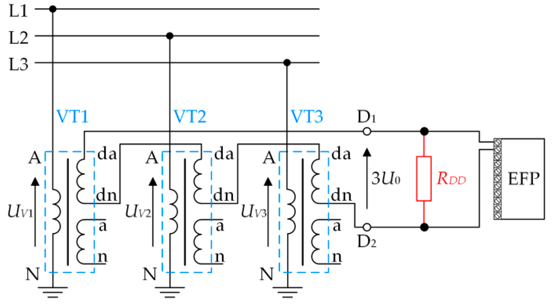
The search for effective solutions to eliminate ferroresonance in electricity networks is an important and current research problem. This is reflected in numerous publications. Various methods are used, but in practice, most commonly, ferroresonance is eliminated with the use of damping resistors connected to the secondary windings of voltage transformers (Figure 2). In power networks with a non-solidly earthed neutral point, the damping resistor (RDD) is connected in the circuit of the open-delta connection (D1–D2) of additional windings of da-dn voltage transformers (VTs). These additional windings are used for measuring the zero-sequence component (3U0) of phase voltages UV1, UV2 and UV3 [17,18]. The 3U0 voltage is one of the input signals for earth fault protection (EFP). In the state of normal operation of the network, 3U0 ≅ 0 V, while in the state of disturbance, e.g., an earth fault or ferroresonance, 3U0 increases. If this increase was caused by a fault, it should be eliminated by earth fault protection (EFP), and if it was caused by ferroresonance, it should be suppressed by an RDD resistor of an appropriately selected value.
The suppression of ferroresonance is possible for RDDRDDmax [19]. The lower the RDD value is, the faster the process proceeds. The value of RDDmax depends on the parameters of the network and voltage transformers. On the other hand, this resistance should meet the condition RDDRDDmin, where RDDmin is the minimum value of resistance resulting from the permissible load capacity of the voltage transformer windings and the amount of energy released in the resistor. In order to ensure the most effective damping of ferroresonance, it is desirable to use resistors with the lowest possible values (even of the order of a few Ω), but then, they cannot be permanently connected to terminals D1–D2. Therefore, advanced damping devices are used, the operation of which is adjusted to the operating condition of the network by means of appropriate control, e.g., using IGBT transistors [20]. In this way, when ferroresonance occurs, the resultant value of the circuit resistance is automatically changed from a high level to a low level. In the state of normal network operation, the device has significant resistance, which does not create high loads on the voltage transformers. The results of research in this area (e.g., [21]) are leading to the construction of devices which have practical applications in electrical power networks. The devices presented in [22,23] are examples of such commercial solutions.
The aim of this paper is to evaluate the effectiveness of ferroresonance damping in auxiliary power systems of high-voltage substations by selected damping devices. Laboratory experiments, the results of which created bases for the development of models of selected damping devices, are presented in Section 2. These models were used to simulate the effectiveness of ferroresonance damping in an auxiliary power system of a 220/110 kV substation (Section 3).
The analyses showed that control systems with different algorithms of operation are used in damping devices. The originality of the scientific contribution is the development of models for these algorithms and their application in the EMTP-ATP simulation program. This knowledge is important when selecting parameters and settings of the applied damping devices for a given network and the disturbances in it.

2. Experimental Studies of Damping Devices and Their Effectiveness

2.1. Testing of Damping Devices

The idea of ferroresonance damping (Figure 2) lies in switching a resistor with a resistance value RDDRDDmax to terminals D1–D2. The higher the effectiveness of ferroresonance damping is, the smaller the value of RDD resistance is. The value of RDDmax depends on many factors, among which, the shape of the characteristic IV = f(UV) of voltage transformers (VTs) is of special importance. As the amount of energy dissipated must be limited, the connection of the resistor to terminals D1–D2 cannot be permanent.
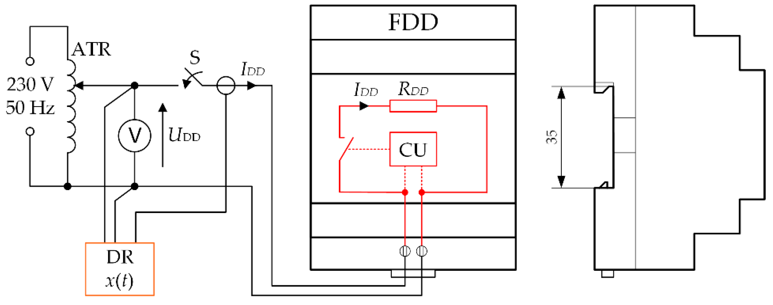
In commercially available devices, the resistor is activated when the threshold voltage (Utr) is exceeded with a time delay (td), for a time dependent on the rated power of the applied resistor. Due to this, the damping device can be miniaturized and installed in low-voltage auxiliary circuits on a 35 mm DIN-rail. Typical values of voltage (Utr) are 20 ÷ 30 V, and times (td) range from 0 to 5 s.
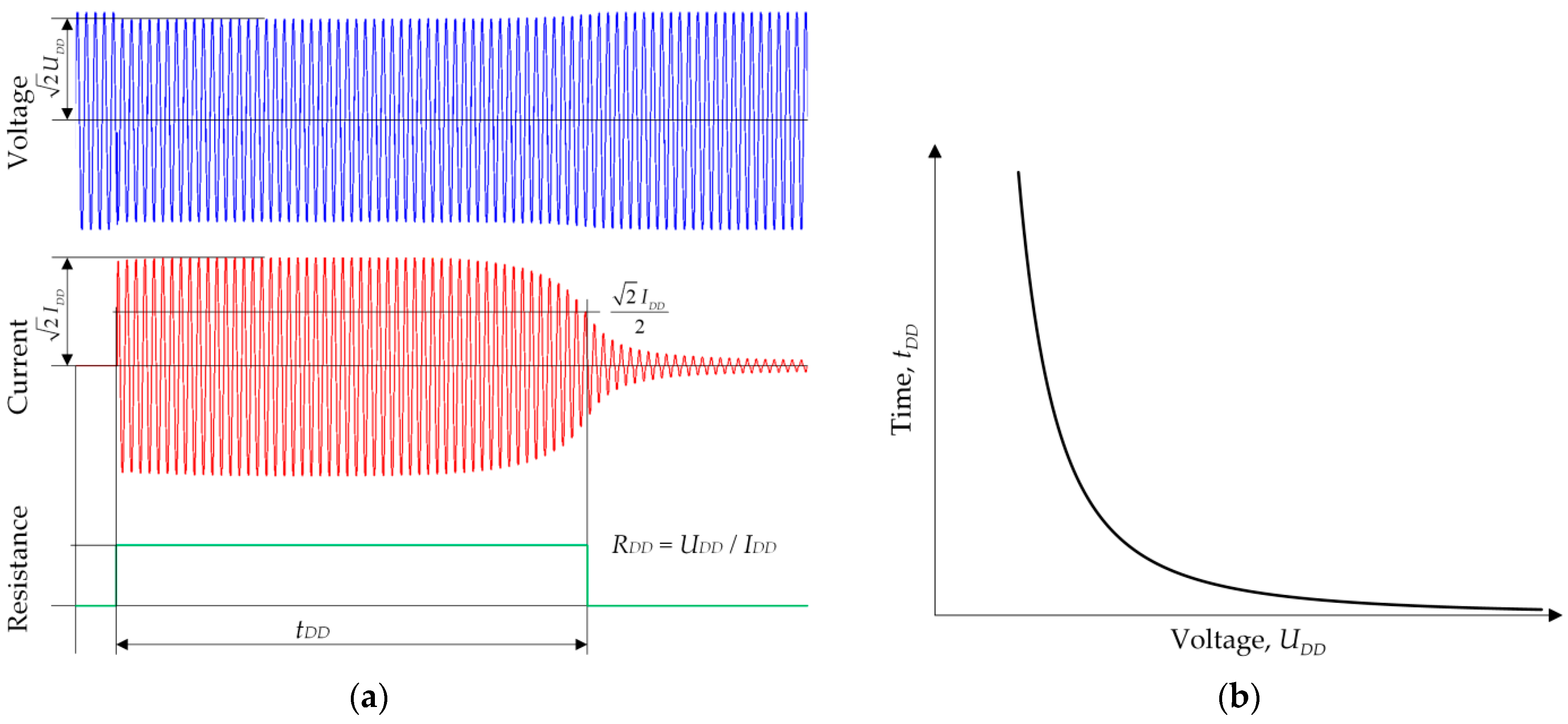
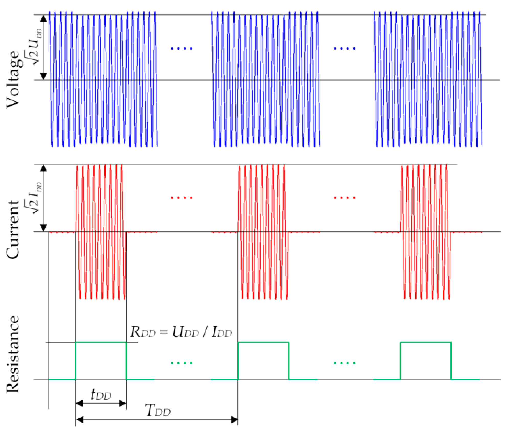
Limiting the amount of energy dissipated is achieved in different ways. On the basis of the research (Figure 3) carried out by authors, two types were distinguished: A-type and B-type. In A-type devices (Figure 4), the damping resistor is a thermistor, so that the limitation of time (IDD) of current flow depends on its value of IDD. In B-type devices (Figure 5), the RDD suppression resistor is pulse-activated by the control unit (CU).
Tests on these devices were carried out for varying values of UDD voltages. They consisted of closing the switch (S) and recording the waveforms of UDD voltages and IDD currents by the digital recorder (DR), such as those shown in Figure 4 and Figure 5. On the basis of these recordings, the parameters of the tested devices, which are relevant for the evaluation of the damping efficiency, were determined. The measured parameters of these devices are shown in Table 1. Furthermore, the determined parameters formed the basis for the development of the computer models of these devices (Section 3). These models were used in the investigation performed in the EMTP-ATP simulation program.

2.2. Investigations in a Laboratory System of the Effectiveness of Ferroresonance Damping Devices

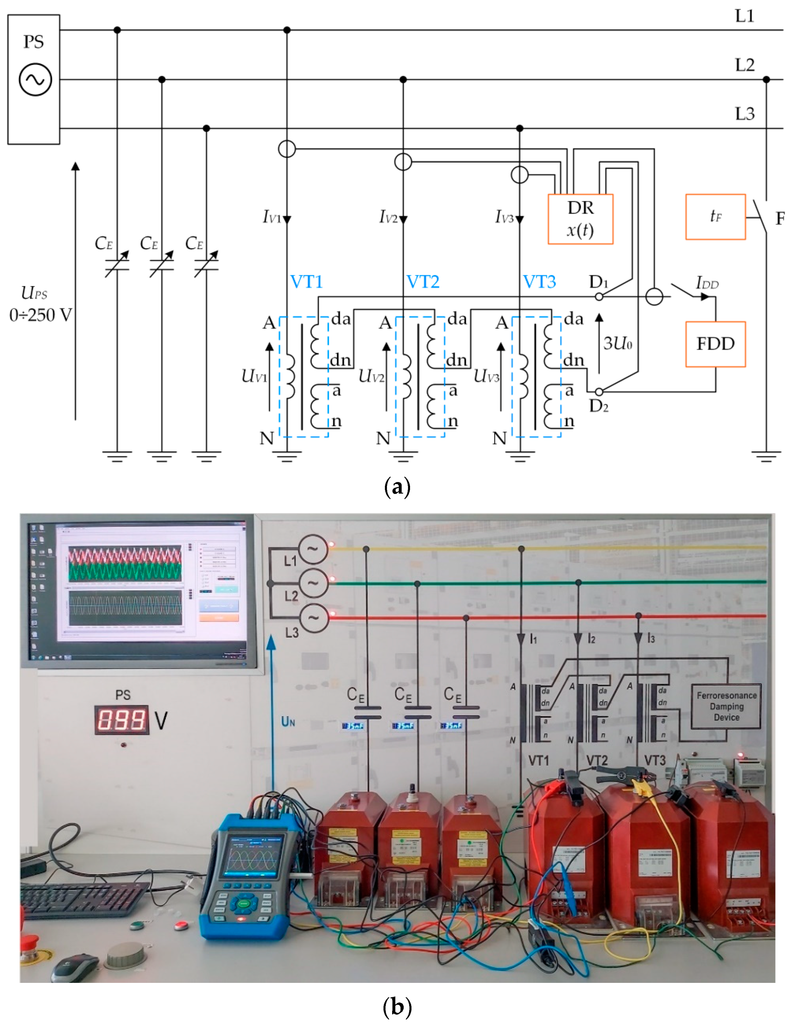
The effectiveness of damping devices was tested in a laboratory system visualized in Figure 6. The system is a model of a medium-voltage power network with an isolated neutral point. The system consists of the following components:
  • Regulated three-phase source of voltage (autotransformer PS), 0–250 V;
  • Regulated capacities CE (0–150 nF), representing the earth capacity of the network;
  • Factory-made low-voltage models of medium-voltage transformers (VTs) with a primary winding 173 V/ 3 , secondary windings 110 V/ 3 and additional windings 100 V/3;
  • Computer-controlled switch F simulating an earth fault which is switched off after time tF;
  • The analyzed damping device (FDD) attached to terminals D1–D2 in a series of windings da-dn of voltage transformers (VTs) (open-delta connection);
  • A digital recorder (DR) (class A portable power quality analyzer NP45 [24]) for measuring and recording analyzed currents and voltages.
Ferroresonance was invoked by closing switch F (Figure 6) and then allowing it to automatically open after a preset time (tF). The assumed switching sequence illustrates the origin of an earth fault in a real medium-voltage power network and its elimination by the power system protection.
The investigations were carried out for different values of capacitance, CE; voltages, UPS; and for two selected FDD damping devices (A-type and B-type). Transient voltage and current waveforms were recorded in the laboratory model (Figure 6).
  • Phase voltages UV1, UV2 and UV3 in the voltage transformer’s primary windings;
  • Phase currents IV1, IV2 and IV3 in the voltage transformer’s primary windings;
  • The tripled zero-sequence component of phase voltages 3U0 = UV1 + UV2 + UV3 (voltage in terminals D1–D2 of open-delta);
  • The current IDD in the open-delta connection–current of the FDD.
  • The recorded voltages and currents waveforms created bases for determining the possibility of the occurrence of ferroresonance in the analyzed system. Moreover, it was possible to assess the effectiveness of operation and ferroresonance damping by selected FDD devices.
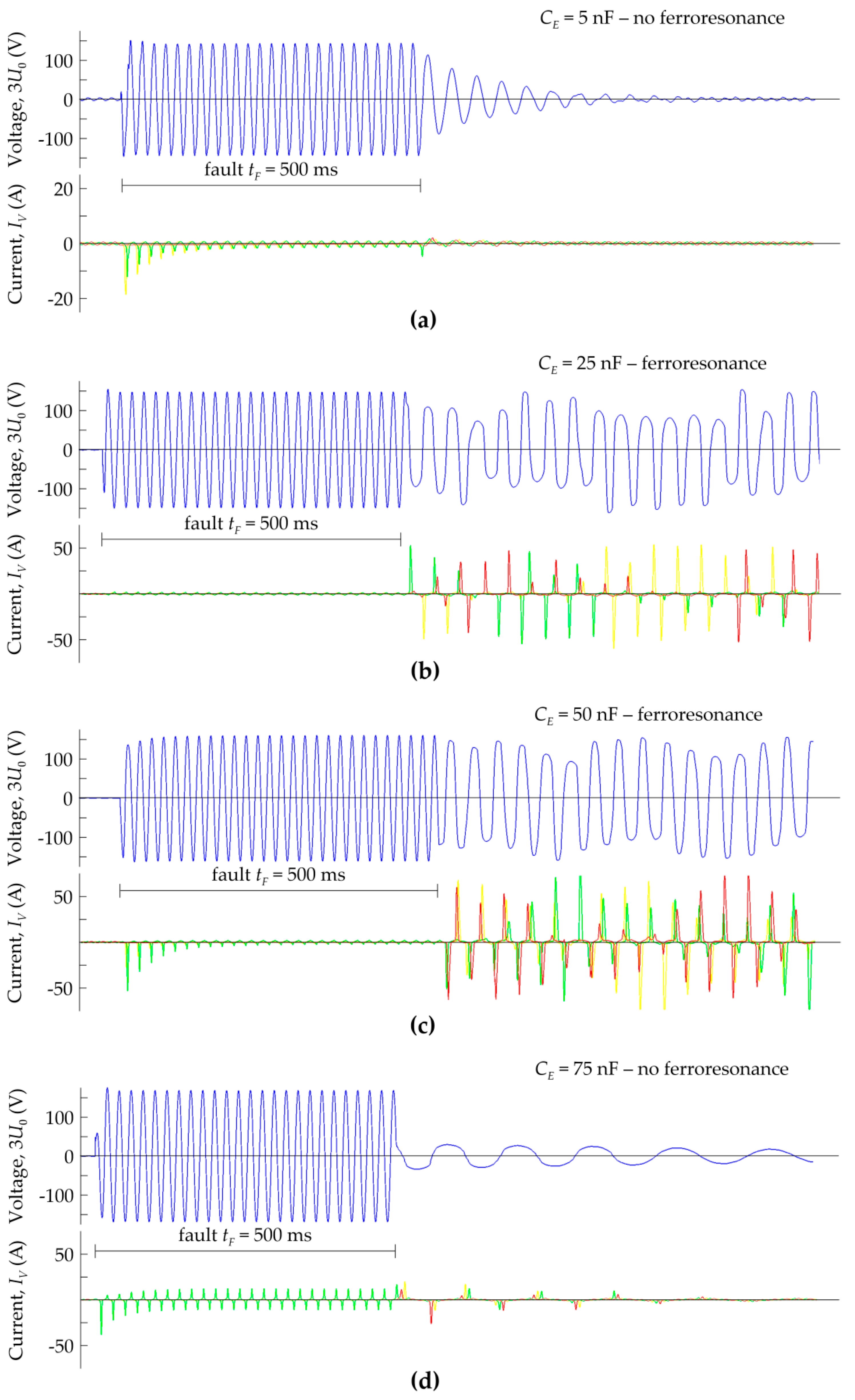
Figure 7 shows exemplary graphs of voltages (3U0) and currents (IV) recorded for UPS = 100 V, time tF = 500 ms and capacitance CE = 5 ÷ 75 nF. As can be seen, the occurrence of the earth fault results in a steady-state voltage (3U0) with a maximum value of approximately 2 100 V, duration tF. Due to the saturation of the transformer cores, rapidly damped currents with peak values of up to about 50 A flow in the primary windings A–N. It can also be observed that capacitances (CE) practically do not affect the values and shapes of voltages and currents during a fault.
Capacitances (CE) have a significant effect on the transient states after the fault has been eliminated. For the capacitance CE = 5 nF (Figure 7a), the voltage (3U0) and currents (IV) are damped shortly after the elimination of the fault. For capacitances CE = 25 nF (Figure 7b) and CE = 50 nF (Figure 7c), the character of the recorded curves changes, which is due to the excitation of the ferroresonance. These curves illustrate the negative effects of this phenomenon, i.e., which are persistent voltage (3U0) and significant overcurrents (IV), which can result in thermal damage to the insulation of the primary windings of the voltage transformers. However, for capacitance CE = 75 nF (Figure 7d), the ferroresonance phenomenon is spontaneously suppressed, which, unlike the curves representing capacitance CE = 5 nF, has a lower oscillation frequency.
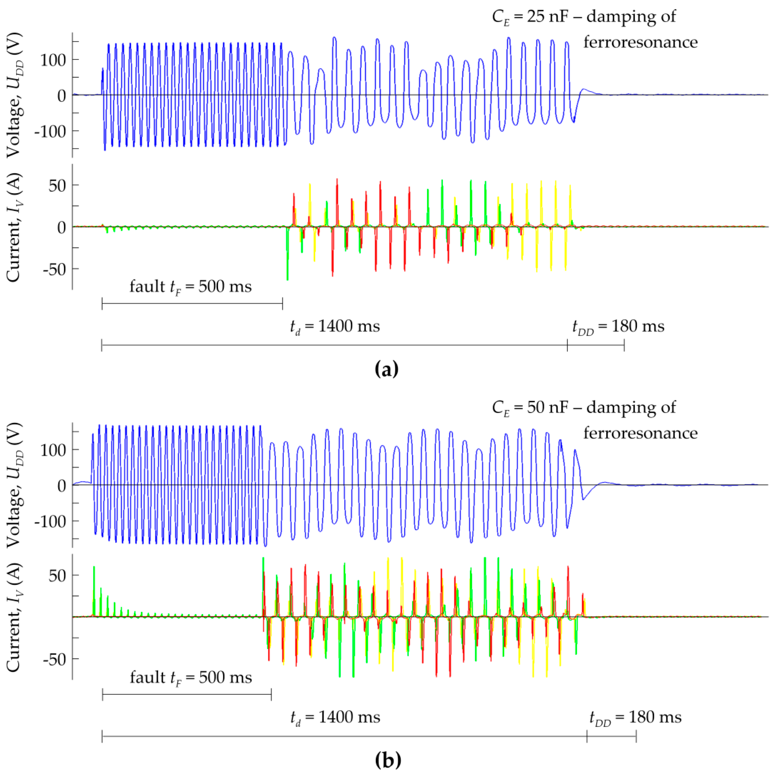
Figure 8 and Figure 9 show the curves of voltages and currents, demonstrating the effectiveness of the considered FDDs (Table 1) in situations of ferroresonant oscillations excited for capacitances CE = 25 nF and CE = 50 nF. Switched to terminals D1-D2, the FDDs affect the course of this phenomenon, causing the expected attenuation of voltages and currents after a fault is off.
The A-type device (Figure 8) starts its operation without delay (time td = 0) when a fault and the resulting voltage (UDD) increase occur. After the time tF = 500 ms, after which, the fault is eliminated, no ferroresonant oscillations are observed in the presented plots. Thus, the A-type device meets the specified requirements, provided the fault time (tF) is shorter than the device operation time (tDD). If this is not met, the FDD will switch off during the short circuit, resulting in ferroresonance excitation, as shown in Figure 7b,c. For this reason, a time delay td > 0 is advisable in practice to effectively coordinate the interaction of the earth fault protection and FDDs.
In the case of the B-type device (Figure 9), the system is activated after time td = 1400 ms from the moment the fault occurred. As a result, the FDD is not burdened by the current (IDD) during the fault, though the resulting ferroresonance lasting tferr = tdtF = 900 ms is generated. After time td, the ferroresonance is suppressed as quickly as in the A-type device.
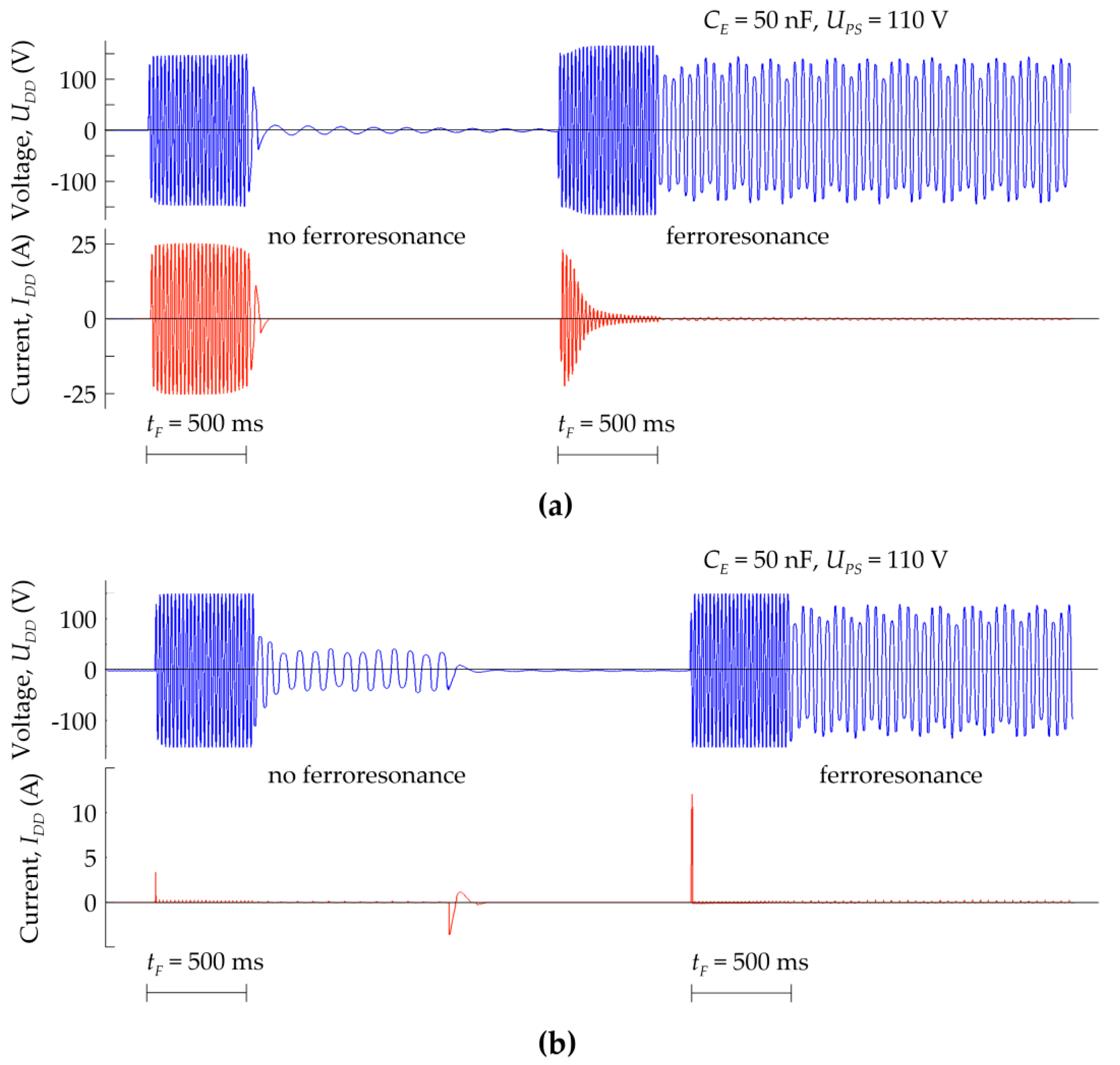
The relatively small RDD values (a few to several ohms) and high values of IDD currents (several to several dozen amperes) result in powers dissipated in the resistor of several hundred or even several thousand watts. The miniaturization of FDDs, however, results in limited energy-dissipation capabilities in the resistor (RDD). This is illustrated in Figure 10a, where the curves of the voltage (3U0) and current (IDD) are shown for an A-type device, recorded for a double short-circuit. These plots show the elimination of ferroresonance after the first fault, though after the second one, the device is unable to damp ferroresonance oscillations due to the increase in the temperature of the thermistor. Such a situation justifies the purposefulness of introducing a delay (td) in the operation of the FDD. On the other hand, however, even with the introduction of a time delay td > 0, the operation of the B-type device may not be effective after the second fault, as illustrated in Figure 10b. However, unlike the A-type device, this inefficiency is due to the programmed timing sequence, in which the RDD resistor is activated cyclically with a period of TDD = 18.5 s. Thus, next time the RDD resistor is activated, the ferroresonance will be certainly damped, though its duration time will be of several seconds.
Due to the lack of thermal models of voltage transformers, it is not possible to determine whether such a long duration of ferroresonance will endanger them, or not.
The analysis of the test results presented in this section confirms that the commercially available ferroresonance damping devices are effective only to some extent. One should be aware of their limited capabilities when selecting the devices for real power systems and coordinating their operation with power system protection. The following section presents the results of simulation studies concentrating on the occurrence and elimination of ferroresonance in the auxiliary power systems of high-voltage substations, using the developed models of A-type and B-type FDDs.

3. Simulation Studies of Ferroresonance Damping Efficiency in an Auxiliary Power System of a 220/110 kV Substation

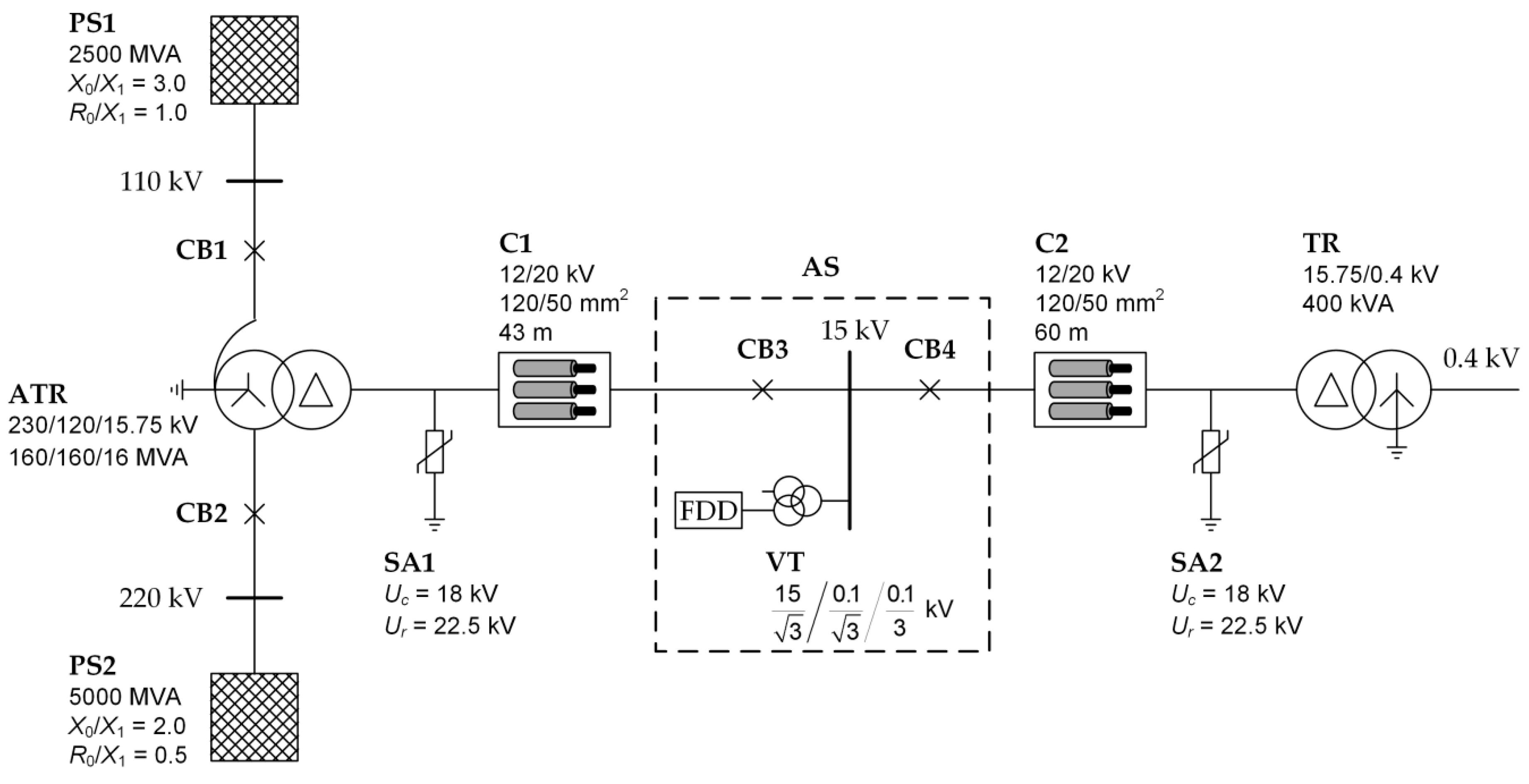
The subject of the study was a 15 kV auxiliary power system, shown in Figure 11. This system consists of the following elements:
  • A 230/120/15.75 kV ATR autotransformer fed by systems PS1 and PS2;
  • A TR 15.75/0.4 kV auxiliary transformer;
  • Cable lines C1 and C2;
  • Voltage transformers (VTs) with a ferroresonance damping device (FDD);
  • Surge arresters SA1 and SA2.
The studies were conducted with the use of a simulation program, EMTP-ATP, where specific elements of Figure 11 were represented.
Transformers ATR and TR and cable lines C1 and C2 were represented with standard models available in EMTP-ATP software: the Hybrid Transformer Model (component XMFR in ATPDraw) and procedure Cable Constants (LCC object in ATPDraw).
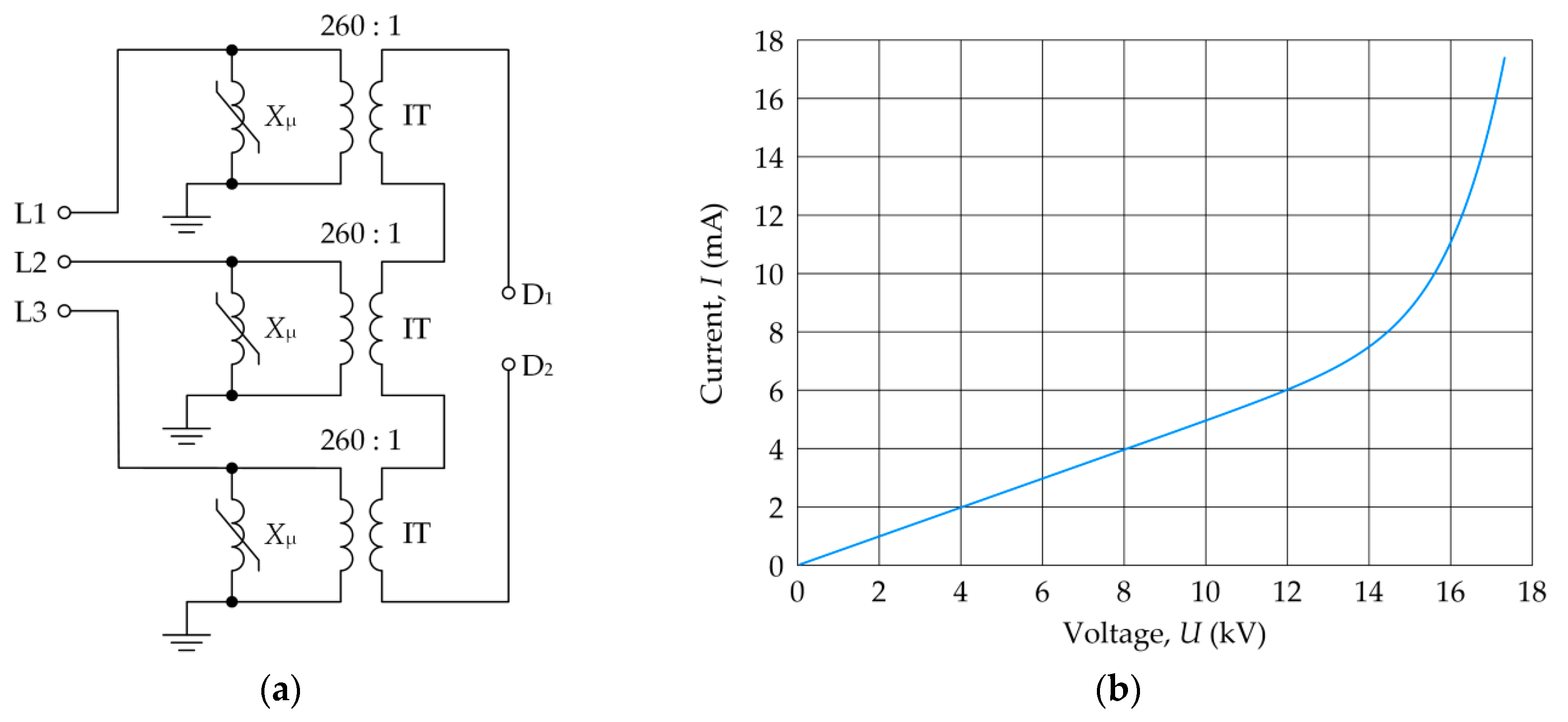
A schematic of the voltage transformer (VT) model is shown in Figure 12a. The model consists of three nonlinear inductances (Xμ) with ideal IT transformers having the following ratio:
ϑ = 15000   V 3 : 100   V 3 260 : 1
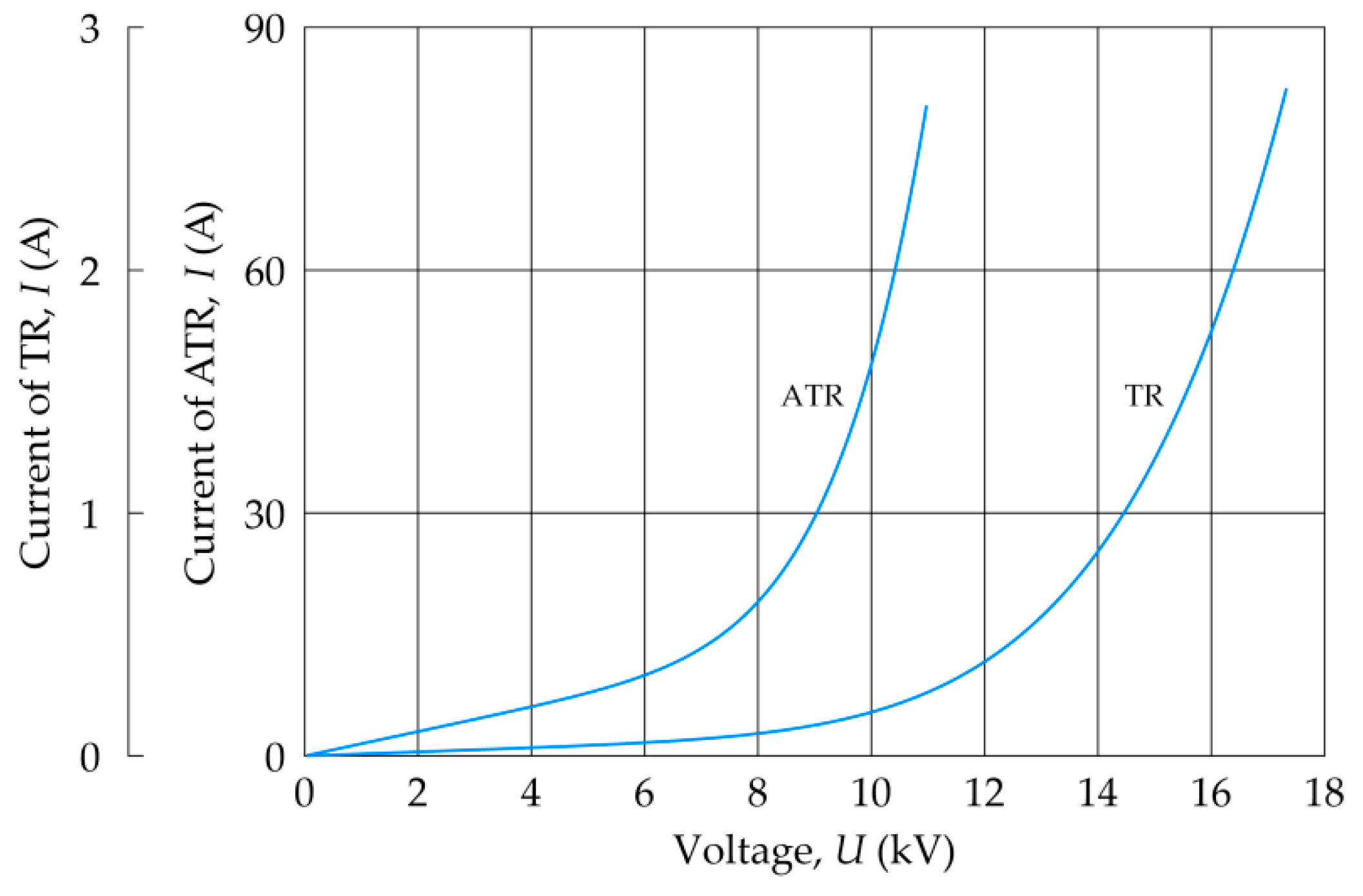
The inductances (Xμ) represent the magnetization characteristics (I(U)) of the VT cores shown in Figure 12b. In Figure 13, the magnetization characteristics of cores of the ATR autotransformer and TR transformer are compared. The secondary windings of the IT transformers are connected in an open-delta system.
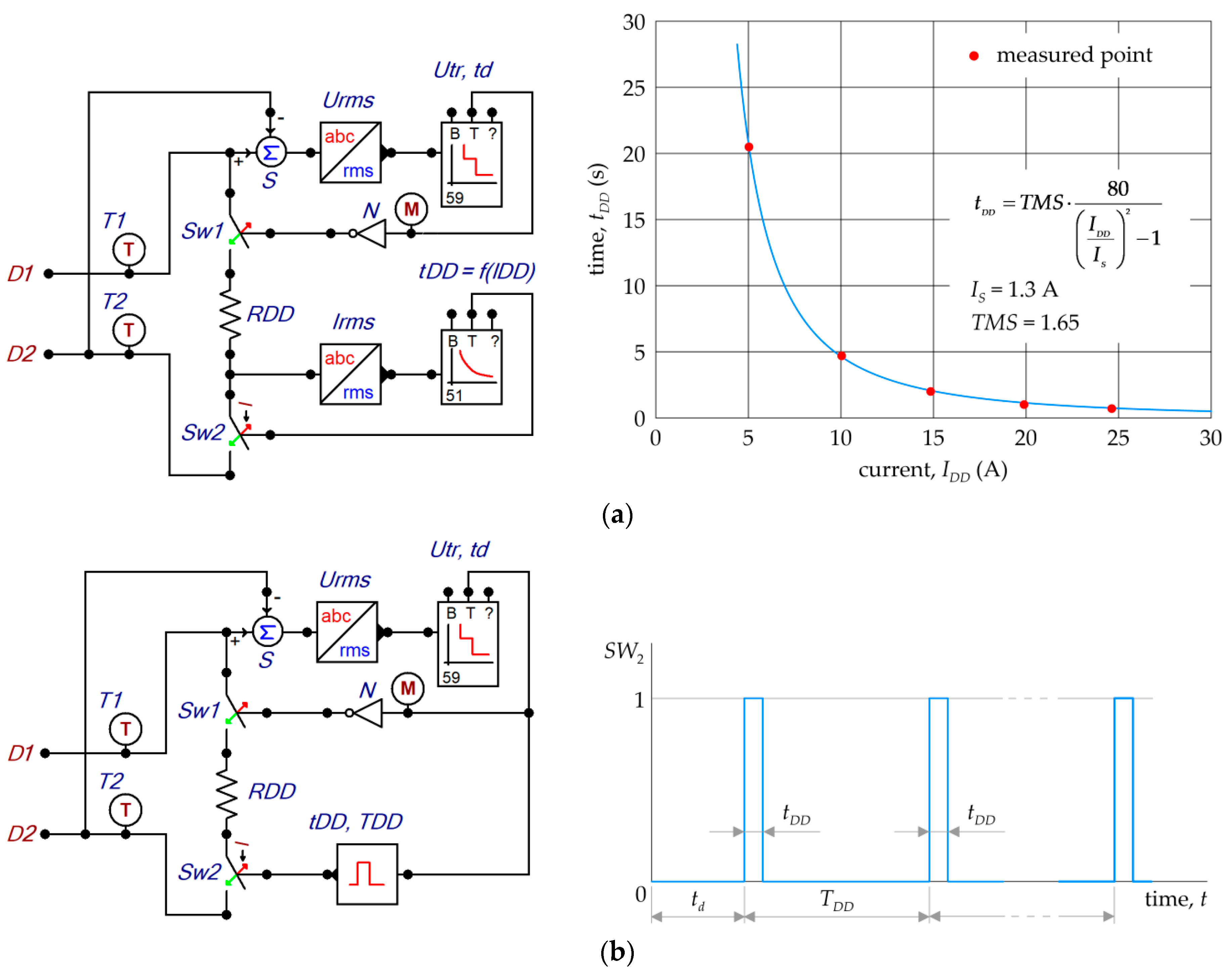
A schematic diagram of the A-type FDD model is shown in Figure 14a. It consists of a 6.6 Ω RDD resistor and two switches, Sw1 (usually open) and Sw2 (usually closed), connected in series. The Sw1 switch is closed by a block implemented in ATPDraw, code 59, which is a model of an independent-time overvoltage relay with the following settings: threshold voltage (Utr) and time delay (td). The input signal is the rms value of the voltage between terminals D1-D2 of the delta-open system of voltage transformers (Figure 12). On the other hand, switch Sw2 is opened by block, code 51, which is a model of inverse definite minimum time (IDMT) overcurrent relay with the EI (Extremely Inverse) characteristic, according to IEC 60,255 [25]. The B-type FDD model (Figure 14b) differs from its A-type equivalent only in the Sw2 switch control block.
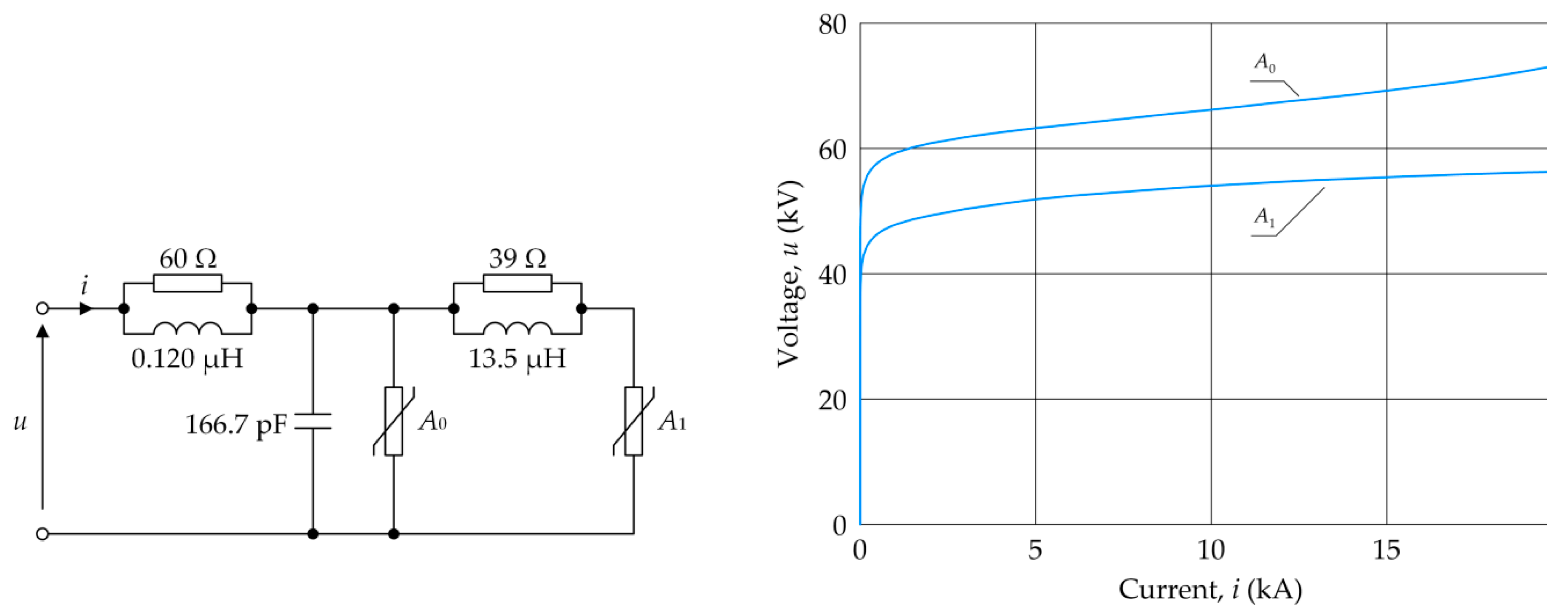
Surge arresters SA1 and SA2 mitigate the effects of ferroresonance, significantly reducing the surge values caused by it. The arrester model proposed by IEEE Working Group 3.4.11 was adopted for the analysis. Its schematic is shown in Figure 15. The values of elements of the surge arrester model are determined iteratively, following the procedure presented in [26].
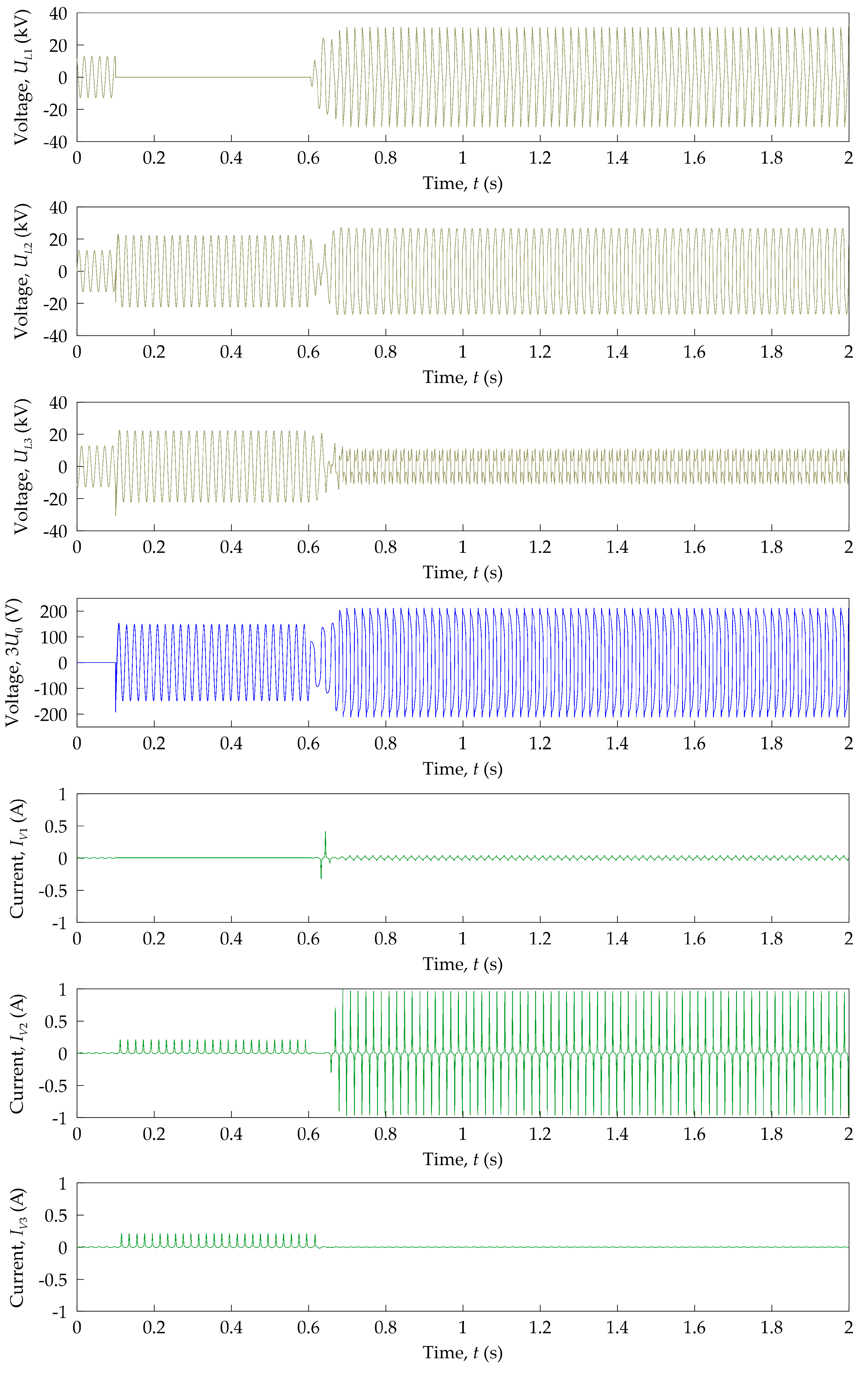
Simulations have shown that one of the possible causes of ferroresonance is to clear an earth fault previously occurring between CB4 and transformer (TR) (Figure 11). Figure 16 shows phase voltages UL1, UL2 and UL3 on substation busbars AS; the tripled zero-sequence voltage component (3U0) of the phase voltages on the open-delta side of the voltage transformers (VTs); and currents IV1, IV2 and IV3 in the primary windings of voltage transformers. It was assumed that the earth fault in the L1 phase occurs at time t = 0.1 s, causing a voltage increase on the undamaged phases L2 and L3, the appearance of 3U0 voltage and an increase in currents IV2 and IV3 due to the saturation of the cores of the voltage transformers. This state lasts to t = 0.6 s, at which time, the CB4 circuit breaker is switched off by the earth fault protection. As a result, ferroresonance is excited in the system with the following consequences: ferroresonant overvoltages (voltages UL1, UL2 and UL3) in the area between the ATR autotransformer and the CB4 open circuit breaker, the lasting and increasing 3U0 voltage and the significant saturation of the core of one of the voltage transformers (current IV2).
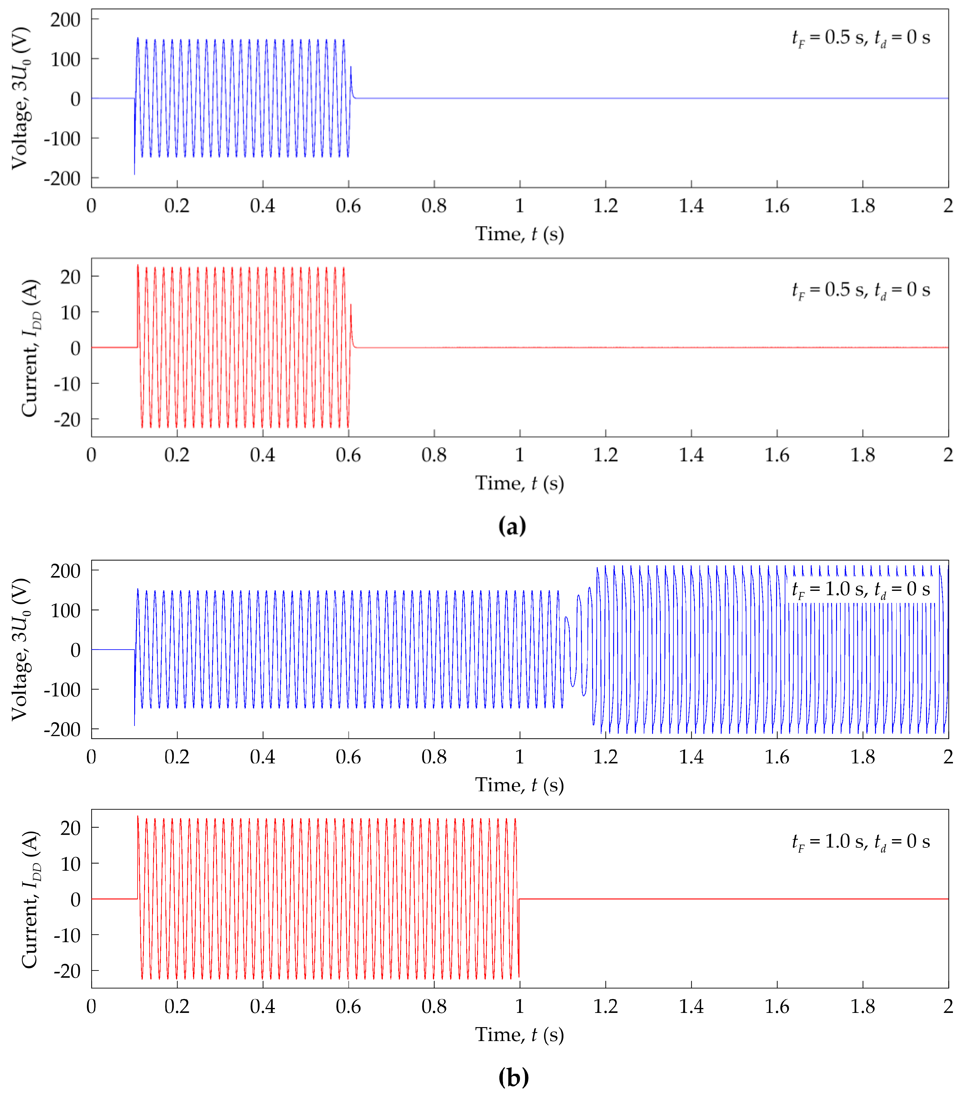
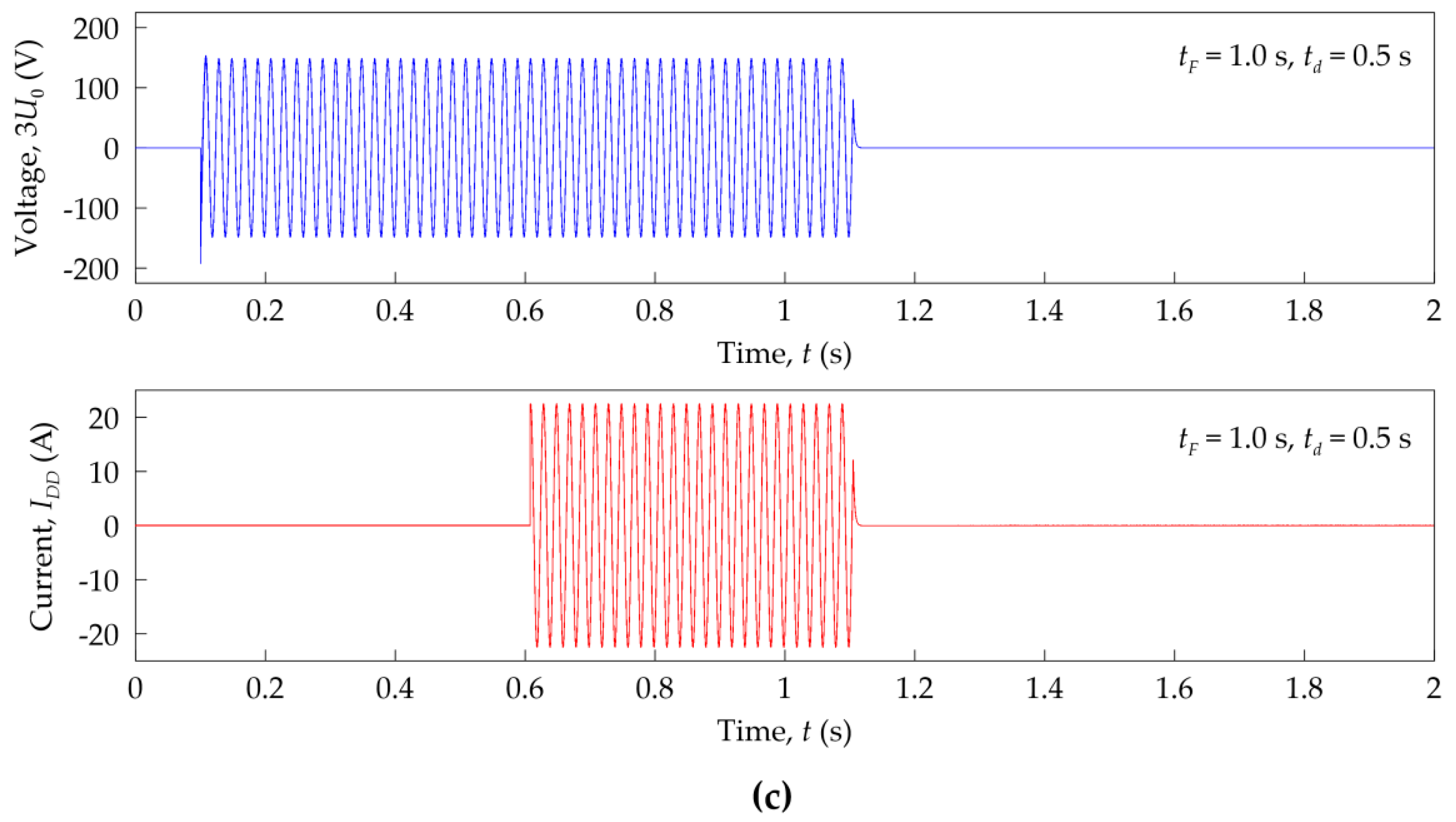
Figure 17 and Figure 18 show the selected voltages and currents illustrating the efficiency of ferroresonance damping by the analyzed A-type and B-type devices. These plots relate to the sequence in Figure 16.
Figure 17a shows the 3U0 voltage and IDD current in an A-type damping device operating immediately (td = 0 s) when the earth fault occurs at time tF = 0.5 s. In this case, the ferroresonance is damped immediately after the earth fault is switched off. Figure 17b shows analogous plots, but for a doubled value of the earth fault time (tF = 1 s). In this case, the ferroresonance was not damped because the FDD got disconnected before the earth fault was switched off at t = 1.1 s, as can be seen from the tDD = f(IDD) characteristic visualized in Figure 14a. Thanks to the use of an appropriate time delay in the operation of the FDD, the ferroresonance can be damped, as shown in Figure 17c for a delay time td = 0.5 s and a time tF = 1 s.
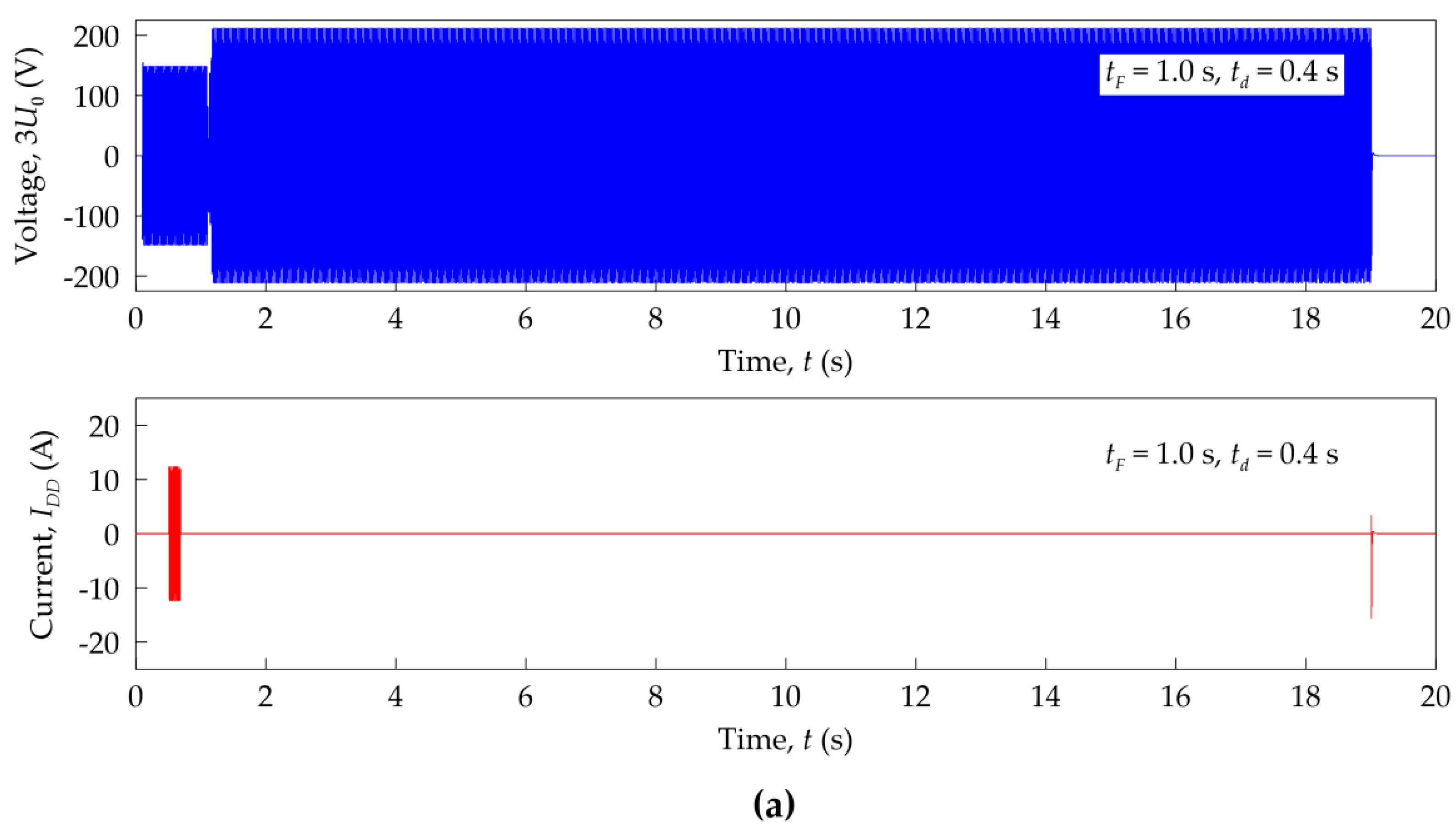
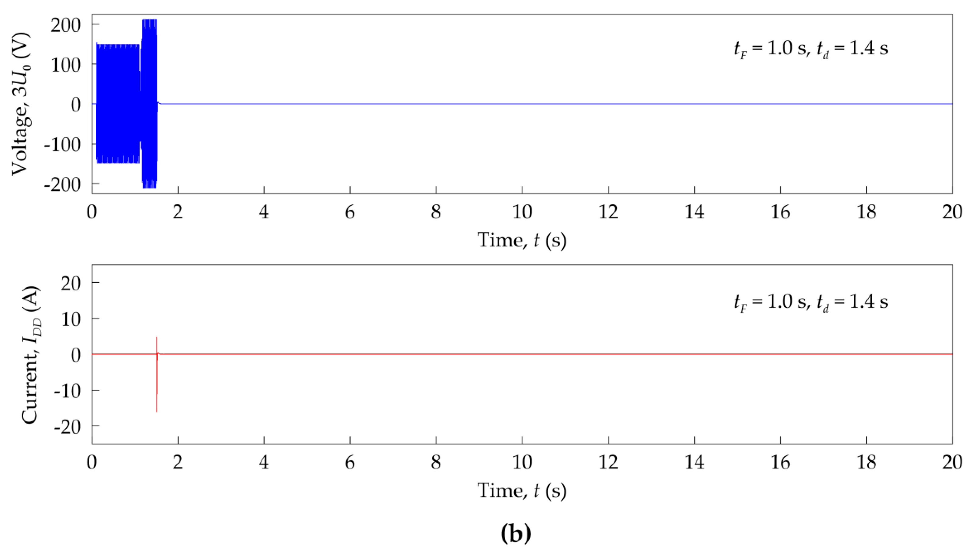
Figure 18a shows the plots of the 3U0 voltage and IDD current in a B-type damping device, for the earth fault time tF = 1 s and the delay time td = 0.4 s. When the earth fault is switched off, ferroresonance is damped only after time TDD = 18.5 s (Table 1). For a longer time td > tF, ferroresonance is damped immediately, as shown in Figure 18b for time td = 1.4 s.

4. Conclusions

Ferroresonance is a dangerous disturbance occurring in power networks; therefore, measures and methods to prevent and eliminate this effect should be sought for and applied. The most common method of eliminating ferroresonance is the use of damping resistors, connected to the secondary windings of voltage transformers. The most effective damping of ferroresonance can be achieved by using resistors with the preferably smallest possible values, even of the order of a few Ω. For this reason, it is the advanced damping devices, the operation of which is adjusted to the work condition of the network, which are used in practice.
The tests carried out on the selected damping devices allowed the essence of their operation to be clarified in detail, their most relevant parameters to be identified and, thus, models to be developed for use in simulation studies in the EMTP-ATP program.
The results of the investigation confirm that commercially available ferroresonance damping devices are effective only to some extent. One should be aware of their limited capabilities when selecting devices for real power systems and coordinating their operation with power system protection.
The simulation studies performed for the auxiliary power system of a 220/110 kV substation confirmed the applicability of the considered ferroresonance damping devices, but with the same constraints as found in the laboratory studies.
The damping device models developed are an important extension of the EMTP-ATP program, allowing them to be applied to other cases of ferroresonance in power grids, such as industrial grids.
This paper is the result of a scientific collaboration between the AGH University of Krakow (Department of Electrical Engineering and Power Engineering) and Technology and the Gdansk University of Technology (Faculty of Electrical and Control Engineering).

Author Contributions

Conceptualization, R.T.; methodology, R.T. and W.N.; software, R.T., W.N. and J.G.; validation, R.T., S.C. and W.N.; formal analysis, R.T. and S.C.; investigation, R.T. and S.C.; resources, R.T.; data curation, R.T.; writing—original draft preparation, R.T., W.N. and S.C.; writing—review and editing, R.T., W.N. and J.G.; visualization, R.T.; supervision, R.T. and S.C.; project administration, R.T.; funding acquisition, R.T. All authors have read and agreed to the published version of the manuscript.

Funding

This research received no external funding.

Data Availability Statement

The original contributions presented in the study are included in the article, further inquiries can be directed to the corresponding author.

Conflicts of Interest

The authors declare no conflicts of interest.

References

  1. Rudenberg, R. Nonharmonic Oscillations as Caused by Magnetic Saturation. Trans. AIEE 1949, 68, 676–685. [Google Scholar] [CrossRef]
  2. Rudenberg, R. Transient Performance of Electric Power Systems; McGraw-Hill Book Company: New York, NY, USA, 1950. [Google Scholar]
  3. Barbisio, E.; Bottauscio, O.; Chiampi, M.; Crotti, G.; Giordano, D. Parameters Affecting Ferroresonance in LCR Electric Circuits. IEEE Trans. Magn. 2008, 44, 870–873. [Google Scholar] [CrossRef]
  4. Mork, B.A.; Stuehm, D.L. Application of nonlinear dynamics and chaos to ferroresonance in distribution systems. IEEE Trans. Power Del. 1994, 9, 1009–1017. [Google Scholar] [CrossRef]
  5. Van Craenenbroeck, T.; Michiels, W.; Van Dommelen, D.; Lust, K. Bifurcation analysis of three-phase ferroresonant oscillations in ungrounded power systems. IEEE Trans. Power Del. 1999, 14, 531–536. [Google Scholar] [CrossRef]
  6. Chen, L.; Yang, Q.; Wang, J.; Sima, W.; Yuan, T. Classification of Fundamental Ferroresonance, Single Phase-to-Ground and Wire Breakage Over-Voltages in Isolated Neutral Networks. Energies 2011, 4, 1301–1320. [Google Scholar] [CrossRef]
  7. Iravani, M.R.; Chaudhary, A.K.S.; Giesbrecht, W.J.; Hassan, I.E.; Keri, A.J.F.; Lee, K.C.; Martinez, J.A.; Morched, A.S.; Mork, B.A.; Parnian, M.; et al. Modeling and analysis guidelines for slow transients. III. The study of ferroresonance. IEEE Trans. Power Del. 2000, 15, 255–265. [Google Scholar] [CrossRef]
  8. International Council on Large Electric Systems. Working Group C4.307. TB 569. Resonance and Ferroresonance in Power Networks; CIGRE: Paris, France, 2014. [Google Scholar]
  9. Thanomsat, N.; Plangklang, B.; Ohgaki, H. Analysis of Ferroresonance Phenomenon in 22 kV Distribution System with a Photovoltaic Source by PSCAD/EMTDC. Energies 2018, 11, 1742. [Google Scholar] [CrossRef]
  10. Kutija, M.; Pravica, L. Effect of Harmonics on Ferroresonance in Low Voltage Power Factor Correction System—A Case Study. Appl. Sci. 2021, 11, 4322. [Google Scholar] [CrossRef]
  11. Staruhina, E.A.; Syutkin, A.V.; Evdokunin, G.A. Investigation of Ferroresonance Processes Leading to Thermal Damage of Cast-Insulated Transformers. In Proceedings of the International Ural Conference on Electrical Power Engineering (UralCon) 2022, Magnitogorsk, Russia, 23–25 September 2022; pp. 213–217. [Google Scholar] [CrossRef]
  12. Mikhak-Beyranvand, M.; Faiz, J.; Rezaei-Zare, A.; Rezaeealam, B. Electromagnetic and thermal behavior of a single-phase transformer during ferroresonance considering hysteresis model of core. Electr. Power Energy Syst. 2020, 121, 106078. [Google Scholar] [CrossRef]
  13. Torres-García, V.; Solís-Ramos, N.; González-Cabrera, N.; Hernández-Mayoral, E.; Guillen, D. Ferroresonance Modeling and Analysis in Underground Distribution Feeders. IEEE Open Access J. Power Energy 2023, 10, 583–592. [Google Scholar] [CrossRef]
  14. Pordanjani, I.R.; Liang, X.; Wang, Y.; Schneider, A. Single-Phase Ferroresonance in an Ungrounded System during System Energization. IEEE Trans. Ind. Appl. 2021, 57, 3530–3537. [Google Scholar] [CrossRef]
  15. Rezaei, S. Impact of Ferroresonance on protective relays in Manitoba Hydro 230 kV electrical network. In Proceedings of the IEEE 15th International Conference on Environment and Electrical Engineering (EEEIC), Rome, Italy, 10–13 June 2015; pp. 1694–1699. [Google Scholar] [CrossRef]
  16. International Council on Large Electric Systems, Working Group 23.04. TB 197. Design Guidelines for Power Station Auxiliaries and Distribution Systems; CIGRE: Paris, France, 2002. [Google Scholar]
  17. Ferracci, P. Ferroresonance. Cahier Technique ECT190; Group Schneider: Rueil-Malmaison, France, 1998. [Google Scholar]
  18. Dedović, M.M.; Mujezinović, A.; Turković, N.; Dautbašić, N.; Turković, I.; Tokić, A.; Bajramović, Z. Experimental investigation of ferroresonance and mitigation measures in 35 kv isolated networks. In Proceedings of the 25th International Conference on Electricity Distribution, Madrid, Spain, 3–6 June 2019. [Google Scholar] [CrossRef]
  19. Piasecki, W.; Florkowski, M.; Fulczyk, M.; Mahonen, P.; Nowak, W. Mitigating Ferroresonance in Voltage Transformers in Ungrounded MV Networks. IEEE Trans. Power Del. 2007, 22, 2362–2369. [Google Scholar] [CrossRef]
  20. Peng, G.; Yuan, S.; Gao, X.; Sun, H. Compound Elimination Method of Potential Transformer Ferroresonance in Distribution Network. In Proceedings of the 9th International Forum on Electrical Engineering and Automation (IFEEA), Zhuhai, China, 4–6 November 2022. [Google Scholar] [CrossRef]
  21. Piasecki, W.; Florkowski, M.; Fulczyk, M.; Mahonen, P.; Luto, M.; Nowak, W.; Preiss, O. Ironing out resonance Ferroresonance prevention in MV voltage transformers. ABB Rev. 2005, 4, 42–46. Available online: https://library.e.abb.com/public/6ca5a3f4bb0ee0ecc1257beb002ba3e3/VT%20Guard-Ironing%20out%20resonance.pdf (accessed on 19 January 2024).
  22. ABB, Medium Voltage Product VT Guard Solution for Ferroresonance Elimination. Available online: https://library.e.abb.com/public/ccc4583980cbdabfc1257beb002bc276/VT%20Guard.pdf (accessed on 19 January 2024).
  23. Orion EE. Ferro-Damp Ferroresonance Solutions. Available online: https://orionee.com/application/files/1816/9409/6135/EN_Ferro-Damp.pdf (accessed on 10 March 2024).
  24. Lumel, S.A.; Góra, Z. NP45—Portable Power Quality Analyzer. Poland. Available online: https://www.lumel.com.pl/resources/Pliki%20do%20pobrania/NP45/NP45_data_sheet.pdf (accessed on 10 March 2024).
  25. IEC 60255-1:2022; Measuring Relays and Protection Equipment—Part 1: Common Requirements. ISO: Geneva, Switzerland, 2023.
  26. IEEE Working Group 3.4.11. Modeling of metal oxide surge arresters. IEEE Trans. Power Del. 1992, 7, 302–309. [Google Scholar] [CrossRef]
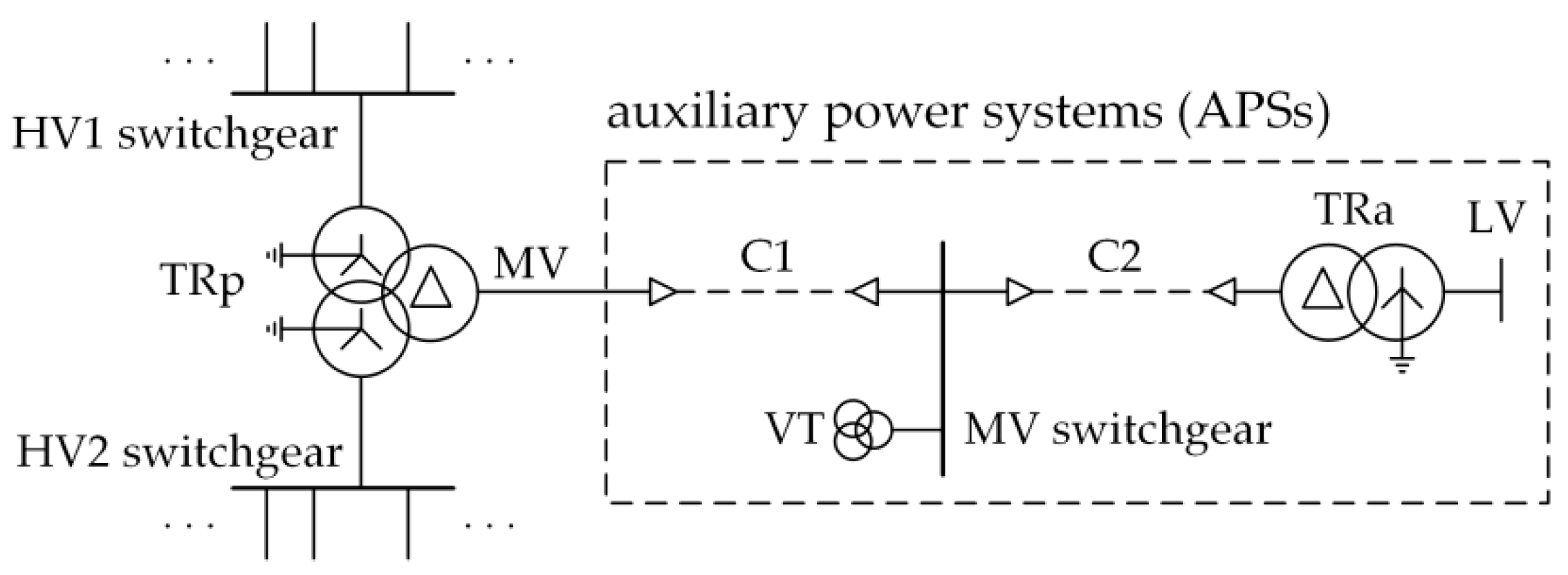
Figure 1. Schematic of a power supply system for a high-voltage substation: TRp—power transformer; TRa—auxiliary transformer; VT—voltage transformers; C1, C2—cable lines; HV, MV, LV—high, medium and low voltage.
Energies 17 02423 g001
Figure 2. Arrangement for measuring symmetrical zero-sequence component of network phase voltages: VT1, VT2, VT3—voltage transformers; RDD—damping resistor; EFP—earth fault protection; UV1, UV2, UV3—voltage on primary windings A–N; 3U0—voltage on open-delta connection with additional windings da-dn.
Energies 17 02423 g002
Figure 3. Schematic of laboratory system for investigation of ferroresonance damping device (FDD): ATR—laboratory autotransformer, S—switch, DR—digital recorder, RDD—damping resistor; CU—control unit; UDD—voltage on damping device terminals; IDD—current of device (of damping resistor).
Energies 17 02423 g003
Figure 4. A-type damping device: (a) recorded voltage and current; (b) the resulting characteristics tDD = f(IDD): UDD—voltage on FDD terminals; IDD—current in FDD; RDD—resistance of damping resistor; tDD—equivalent operating time.
Energies 17 02423 g004
Figure 5. Recorded voltage and current for B-type damping device: UDD—voltage on FDD terminals; IDD—current in FDD; RDD—resistance of damping resistor; tDD—pulse duration; TDD—time between pulses.
Energies 17 02423 g005
Figure 6. Scheme (a) and view (b) of laboratory system for analyzing the efficiency of ferroresonance damping: PS—adjustable source of three-phase voltage UPS; CE—adjustable shunt capacitors of the network model; VT1, VT2, VT3—voltage transformers; F—fault; FDD—ferroresonance damping device; DR—digital recorder; UV1, UV2, UV3—voltage in primary windings A–N; IV1, IV2, IV3—currents in primary windings A–N; 3U0—voltage in open-delta connection of additional winding da-dn; IDD—current of damping device; tF—short circuit switch-off time.
Energies 17 02423 g006
Figure 7. Recorded voltages (3U0) and currents (IV) for (a) CE = 5 nF; (b) CE = 25 nF; (c) CE = 50 nF; (d) CE = 75 nF.
Energies 17 02423 g007
Figure 8. Recorded voltages (3U0) and currents (IV) in A-type FDD for (a) CE = 25 nF; (b) CE = 50 nF.
Energies 17 02423 g008
Figure 9. Recorded voltages (3U0) and currents (IV) in B-type FDD for (a) CE = 25 nF; (b) CE = 50 nF.
Energies 17 02423 g009
Figure 10. Recorded voltages (3U0) and currents (IV) for CE = 50 nF: (a) A-type FDD; (b) B-type FDD.
Energies 17 02423 g010
Figure 11. Schematic of analyzed auxiliary power system for a 220/110 kV substation: PS1—110 kV power system; PS2—220 kV power system; ATR—power autotransformer; TR—auxiliary transformer; C1, C2—cable lines; AS—auxiliary switchgear; VT—voltage transformers; FDD—ferroresonance damping device; SA1, SA2—surge arresters, CB1, CB2, CB3, CB4—circuit breakers; R0, X0, X1—symmetrical component resistance and reactances, Uc—SA continuous operating voltage, Ur—SA rated voltage.
Energies 17 02423 g011
Figure 12. Model of voltage transformers: (a) schematic; (b) characteristic I(U) of reactance (Xμ), Xμ—magnetizing reactance; IT—ideal transformer.
Energies 17 02423 g012
Figure 13. Characteristic I(U) of magnetizing reactance (Xμ) (from 15.75 kV side): ATR—power autotransformer 230/120/15.75 kV; TR—auxiliary transformer 15.75/0.4 kV.
Energies 17 02423 g013
Figure 14. ATPDraw models of FDDs and characteristics of switch control Sw2: (a) A-type FDD; (b) B-type FDD: 59—independent-time overvoltage relay model; 51—inverse definite minimum time (IDMT) relay model; T1, T2—probes for passing node voltages to TACSs (Transient Analysis Control Systems); S—TACS summator (subtraction); abc/rms—model for calculation of signal rms value; M—probe for passing value from MODELS into TACS; N—TACS negator; tDD –opening time; IDD—resistor RDD current; IS—relay setting current; TMS—time multiplier setting.
Energies 17 02423 g014
Figure 15. Model of a surge arrester and u-i characteristic of the A0 and A1 nonlinear elements.
Energies 17 02423 g015
Figure 16. Calculated voltages and currents, as in Figure 11, caused by earth fault and its switching off in circuit without an FDD: UL1, UL2, UL3—phase voltages on substation busbars AS; 3U0—tripled zero-sequence voltage component on the side of open-delta voltage transformers (VTs); IV1, IV2, IV3—currents in primary windings of voltage transformers; t = 0.1 s—earth fault moment; t = 0.6 s—moment of earth fault elimination.
Energies 17 02423 g016
Figure 17. Calculated time curves illustrating the efficiency of ferroresonance damping by an A-type FDD: (a) instantaneous operation for time tF = 0.5 s; (b) instantaneous operation for time tF = 1.0 s; (c) delayed time td = 0.5 s for time tF = 1.0 s; 3U0—tripled zero-sequence voltage component on the side of open-delta voltage transformers (VTs); IDD—current of FDD.
Energies 17 02423 g017aEnergies 17 02423 g017b
Figure 18. Calculated time curves illustrating the efficiency of ferroresonance damping by a B-type FDD: (a) operation for time tF = 1 s with time delay td = 0.4 s; (b) operation for time tF = 1 s with time delay td = 1.4 s; 3U0—tripled zero-sequence voltage component on the side of open-delta voltage transformers (VTs); IDD—current of FDD.
Energies 17 02423 g018aEnergies 17 02423 g018b
Table 1. Measured parameters of analyzed FDD.
ParameterFDD Type AFDD Type B
RDD (Ω)6.612.0
tDD (s)tDD = 22,130 × (UDD)−2.20.18
TDD (s)N/A18.5
td (s)00.4; 1.4; 2.4; 3.4
Utr (V)3020; 25; 30
RDD—resistance of damping resistor, tDD—equivalent operating time or pulse duration, TDD—time between pulses, td—time delay, Utr—threshold voltage, UDD—voltage on FDD terminals.
Disclaimer/Publisher’s Note: The statements, opinions and data contained in all publications are solely those of the individual author(s) and contributor(s) and not of MDPI and/or the editor(s). MDPI and/or the editor(s) disclaim responsibility for any injury to people or property resulting from any ideas, methods, instructions or products referred to in the content.