Article

Aspen Simulation Study of Dual-Fluidized Bed Biomass Gasification

1
China Coal (Tianjin) Underground Engineering Intelligent Research Institute Co., Ltd., Tianjin 300131, China
2
Energy Research Institute, Qilu University of Technology (Shandong Academy of Sciences), Jinan 250014, China
*
Author to whom correspondence should be addressed.
Energies 2024, 17(10), 2381; https://doi.org/10.3390/en17102381
Submission received: 28 February 2024 / Revised: 3 May 2024 / Accepted: 6 May 2024 / Published: 15 May 2024
(This article belongs to the Section I3: Energy Chemistry)

Abstract

:
This article establishes a thermodynamic model of a dual-fluidized bed biomass gasification process based on the Aspen Plus software platform and studies the operational control characteristics of the dual-fluidized bed. Firstly, the reliability of the model is verified by comparing it with the existing experimental data, and then the influence of different process parameters on the operation and gasification characteristics of the dual-fluidized bed system is investigated. The main parameters studied in the operational process include the fuel feed rate, steam/biomass ratio (S/B), air equivalent ratio (ER), and circulating bed material amount, etc. Their influence on the gasification product composition, reactor temperature, gas heat value (QV), gas production rate (GV), carbon conversion rate (ηc), and gasification efficiency (η) is investigated. The study finds that fuel feed rate and circulating bed material amount are positively correlated with QV, ηc, and η; ER is positively correlated with GV and ηc but negatively correlated with QV and η; S/B is positively correlated with GV, ηc, and η but negatively correlated with QV. The addition of CaO is beneficial for increasing QV. In actual operation, a lower reaction temperature in the gasification bed can be achieved by reducing the circulating bed material amount, and a larger temperature difference between the combustion furnace and the gasification furnace helps to further improve the quality of the gas. At the same time, GV, ηc, and η need to be considered to find the most optimized operating conditions for maximizing the benefits. The model simulation results agree well with the experimental data, providing a reference for the operation and design of dual-fluidized beds and chemical looping technology based on dual-fluidized beds.

1. Introduction

The dual-fluidized bed (DFB) technology fits well with the two-step reaction process in the traditional chemical loop, making the chemical loop reactor often adopt a circulating dual-bed structure. The dual-fluidized bed gasification technology can separate the pyrolysis gasification and semi-coke combustion of solid fuels (such as coal and biomass) using the high-temperature circulating bed material to provide heat for the gasifier and obtain medium- to high-calorific-value gas without using pure oxygen or enriched oxygen gasification agents. The dual-bed technology and chemical loop technology based on dual-bed reactors have been widely studied [1,2,3,4,5,6,7,8].
The dual-fluidized bed system is an intricately coupled system where the processes interact deeply and are difficult to regulate independently with a single parameter. Conducting detailed experimental research and analysis of the influence of various factors on the gasification characteristics is both time-consuming and challenging. Moreover, single experiments are typically limited by the experimental conditions, making comprehensive and accurate analysis difficult. The adoption of numerical simulation methods to simplify the processes and focus on key factors for calculation and analysis has gradually gained acceptance. Among the numerous simulation studies, Aspen Plus 7.2 (Advanced System for Process Engineering) is a worldwide standard process simulation software. It is widely used in processes such as coal-to-synthetic natural gas [9], syngas to methanol [10], gasification of coal, and partial gasification for hydrogen production [11], process simulation, and system performance evaluation due to its extensive reserves of physical property data, rich process unit models, and precise and effective model calculation and analysis capabilities.
This paper investigates the operational control characteristics of the dual-fluidized bed, providing a reference for the operation and design of dual-fluidized bed technology and chemical loop technology based on dual-fluidized beds. Firstly, the reliability of the model is verified through a comparison with the existing experimental data, and then the influence of different process parameters on the operation of the dual-fluidized bed system and its gasification characteristics is examined. The main research focuses on the influence of important parameters such as the steam/biomass ratio (S/B), air equivalent ratio (ER), and circulating bed material mass on the composition of the gasification products, reactor temperature, gas heating value (QV), gas production rate (GV), carbon conversion rate (ηc), and gasification efficiency (η) during the operational process.

2. Materials and Methods

2.1. Experimental Device

The dual-fluidized bed gasification system diagram and physical image are shown in Figure 1. Relevant research data using quartz sand as bed material have been published [12,13] and will not be elaborated upon here. This paper will directly reference literature data to validate the rationality of the Aspen dual-fluidized bed reactor model.
The annual emissions of traditional Chinese medicine residues in China reach up to 30 million tons. Traditional Chinese medicine residue has a high water content and certain nutritional components, making it prone to spoilage and causing serious environmental pollution. The biomass raw materials used in this study were traditional Chinese medicine residues provided by a pharmaceutical company in Shandong Province, with an initial water content of about 70%. The raw material is a mixture, and there is no fixed molecular structure in the simulation software that can accurately describe it. Here, the definition of coal in Aspen Plus [14] is used for reference. After natural drying, crushing, and screening, the particle size of about 5 mm with about 5% water content of material was selected as the experimental raw materials. The data of its air-dried basis properties are shown in Table 1. The research results of the dual-fluidized bed gasification experiment using this raw material have been published [12].

2.2. Physical Model

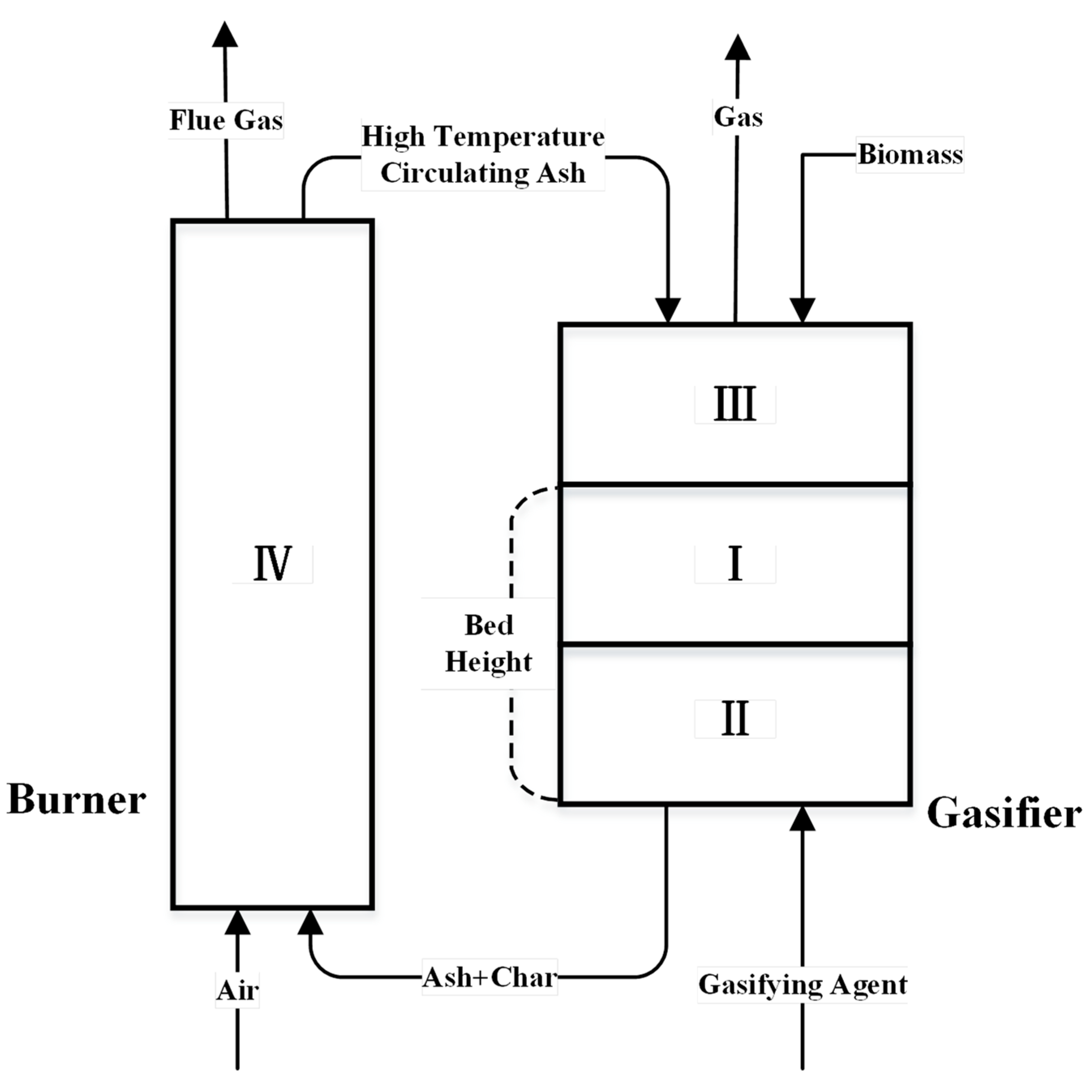
The dual-fluidized bed gasification process generally consists of three processes: pyrolysis, gasification, and combustion. According to the main reaction, the entire dual-fluidized bed system can be divided into four regions: I, II, III, and IV (see Figure 2) [13]. Ideally, each region should complete the following corresponding reactions.
Zone I is the raw material layer, located in the middle layer of the gasification furnace reaction zone. The biomass raw materials are heated and dried by high-temperature circulating bed materials. At the same time, the biomass undergoes pyrolysis reactions to produce pyrolysis gas, semi-coke, and tar.
The reaction equation is as follows:
Biomass → Char + Tar + Gases (CO, H2, CH4, CO2, H2O, CnHm)
Zone II is located at the lower part of the raw material layer, and the semi-coke reacts with the gasification agent (air or water vapor) as follows:
2C + O2 → 2CO
C + H2O → CO + H2
Zone III is located above the raw material layer. The main reactions that occur include gas component transformation and tar cracking as follows:
CO + H2O → CO2 + H2
Tar → CO + H2 + CO2 + CH4 + CnHm
Under the condition of steam gasification agent, the volume content of CnHm in the generated gas of biomass is generally less than 3%. Therefore, in this study, the presence of CnHm was ignored to simplify the model and calculation.
Zone IV is located in the combustion furnace, where semi-coke and air undergo combustion reactions:
C + O2 → CO2

2.3. Aspen Plus Dual-Fluidized Bed Gasification Model

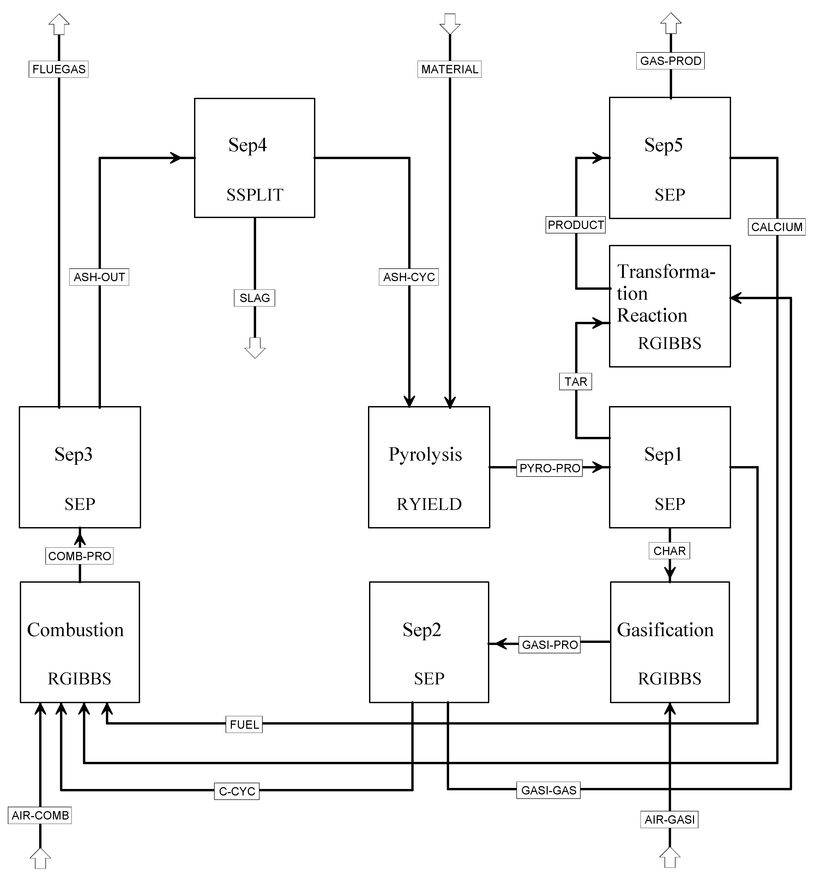
Based on the division of the biomass gasification reaction zones in a dual-fluidized bed and the operational characteristics of the system, the entire gasification process is divided into four parts for simulation: pyrolysis, gasification, shift reaction, and combustion zones. The following assumptions and settings are relevant:
(1)
The tar components are complex and have a low target yield, so the influence of tar is ignored in the simulation;
(2)
All components of the biomass, except for char (fixed carbon and ash), are converted into gas;
(3)
Char consists only of fixed carbon and ash;
(4)
The ash is an inert component that does not participate in the reaction, and it is assumed that all the ash is contained in the char in the solid products [15];
(5)
The heat loss of the entire system is a fixed value independent of the amount of feedstock added;
(6)
The cycled ash entering the gasifier is defined as the tearing stream (Tear).
The simulation process of the biomass dual-fluidized bed gasification reaction model is shown in Figure 3. This model includes modules for pyrolysis (Pyrolysis), transformation reaction (Transformation Reaction), semi-char gasification (Gasification), combustion (Combustion), and five separation modules (Sep1–5). The corresponding Aspen Plus models and their main functions in the simulation are shown in Table 2.
Pyrolysis reactions are based on the Ryield module, which only calculates yield equilibrium. In terms of property selection, the Aspen Plus software user guide recommends property methods for syngas applications, including PR–BM (Peng–Robinson with Boston–Mathias) and RKS–BM (Redlich–Kwong–Soave with Boston–Mathias) [16,17,18]. Through literature research and analysis, this paper selects the PR–BM equation as the global property method [19,20]. Considering the reactivity and complexity of the reduction and oxidation processes, the transformation reaction module, semi-coke gasification module, and combustion module in this paper all adopt the Rgibbs equilibrium reactor for simulation [21,22]. Currently, there is no universally accepted explanation for the specific chemical reactions and kinetic characteristics of the biomass gasification process. Using the Gibbs free energy minimization method to simulate actual chemical processes is a common approach. However, since complete chemical equilibrium is not reached in actual reactions, the results obtained from the Gibbs free energy minimization method may differ from experimental results. Through embedded Fortran subroutines, the functional relationships between various parameters in the system are adjusted, including five Fortran subroutines (Flow sheeting Options | Calculator). During the simulation, biomass and ash are input as unconventional substances, while conventional substances include H2O, O2, N2, C, H2, CaO, CaCO3, S, CO, CO2, CH4, and H2S, among others.

3. Results and Discussion

3.1. Comparison of Numerical Simulation and Experimental Data

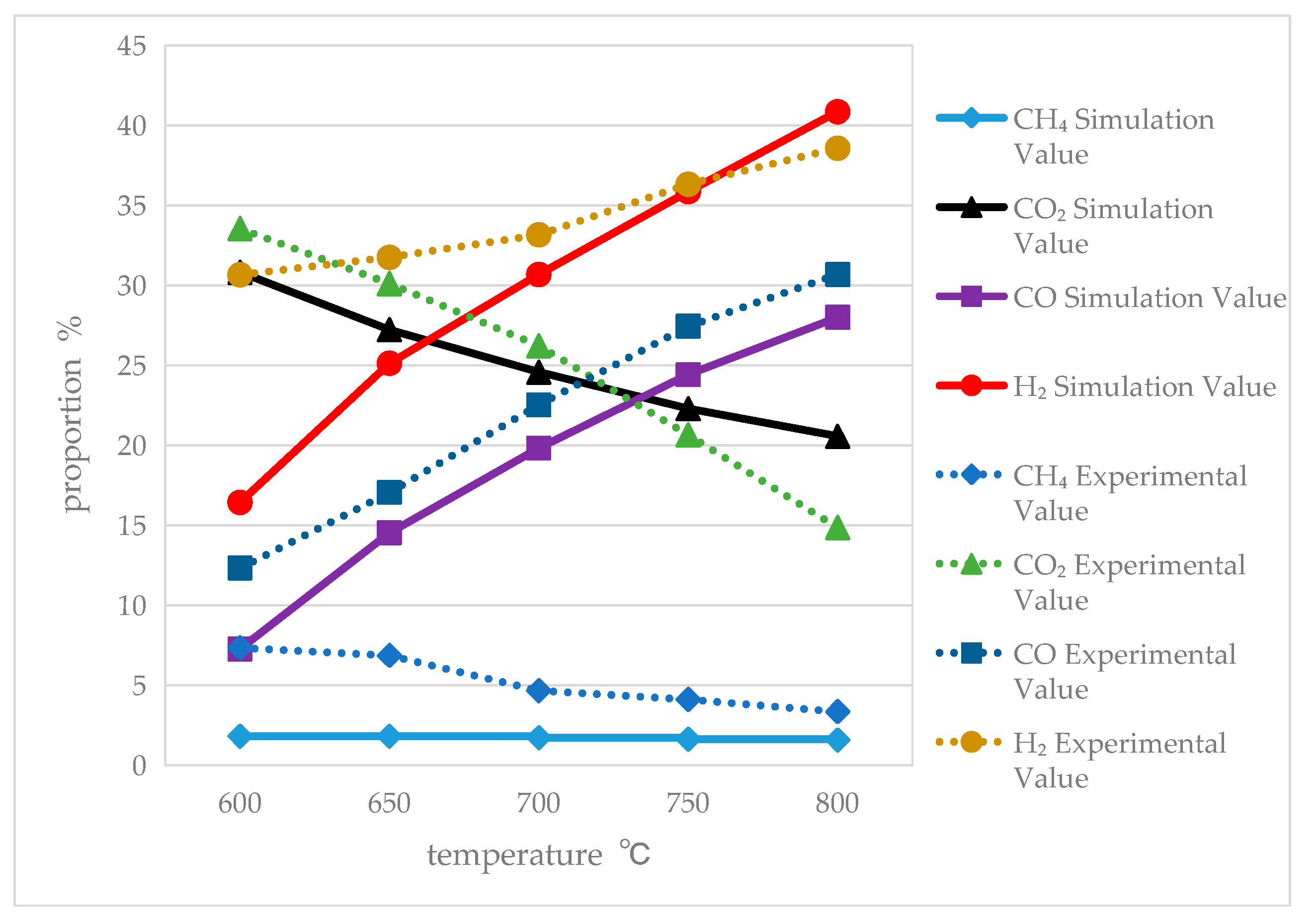
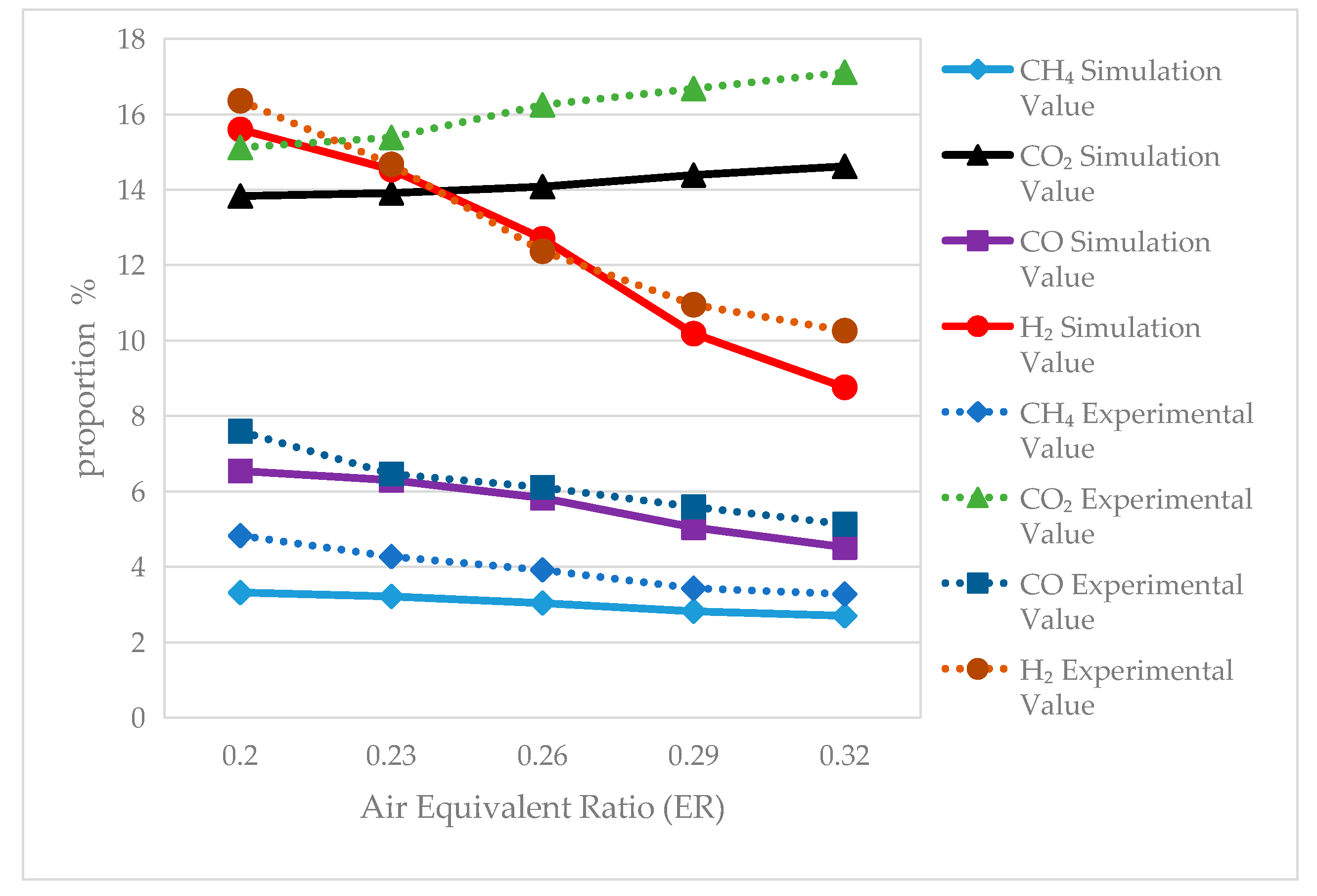
To verify the accuracy and reliability of the model, a comparison experiment was conducted by comparing a portion of the calculated results with existing experimental data. The experimental data were obtained from the aforementioned experimental setup, and the related articles have been published [12,13]. Subsequently, the sensitivity analysis function of the Aspen Plus software was utilized to simulate the influence of different process parameters on the pyrolysis and gasification characteristics. The simulated curves of the gas composition varying with the gasifier temperature, as well as the comparison with the experimental data, are shown in Figure 4. In the dual-fluidized bed biomass pyrolysis and gasification system, the temperatures in each region are variables of the control parameters, such as feed rate and air flow rate. Figure 5 presents the simulated curves of the gas composition varying with the air-to-fuel equivalent ratio (ER), along with a comparison of the simulated data with the experimental measurements.
From Figure 4, it can be observed that, as the temperature increases, ϕH2 and ϕCO gradually increase while ϕCO2 and ϕCH4 gradually decrease. In the Aspen Plus simulation process, the composition of the gas is determined by both the gas reaction temperature and the distribution of the elements. The experimental values agree closely with the simulated values and exhibit the same change trend. In Figure 4, in the low-temperature range, the calculated hydrogen is approximately 2 times less (16% versus 30%) than the experimental one, and the calculated methane is 3.5 times lower than the experimental one (2% versus 7%). This may be because the calculated data are based on the Gibbs free energy minimization principle for the C, H, and O elements and H2O molecules, without considering the actual kinetic mechanism of the biomass during pyrolysis. In the actual biomass gasification process, the formation and cracking of tar are important mechanisms for the formation of H2 and CH4, especially in the low-temperature stage, which can seriously affect the composition of the gasification products. As shown in Figure 4, the higher the temperature, the more the calculated and experimental values tend to converge. This should be because, the higher the temperature, the more in line with the chemical thermodynamic equilibrium state. From Figure 4 and Figure 5, it can be seen that the results of the model’s simulation calculations are close to the experimental measured values, which verifies the model’s rationality to some extent.

3.2. Simulation Results and Analysis under Different Influencing Factors

The main factors influencing the dual-fluidized bed biomass gasification process and the quality of the produced gas include the feedstock feed rate, circulating bed material flow rate, air-to-fuel ratio (ER), and the steam-to-biomass mass ratio (S/B), among others. During the Aspen Plus simulation, the Model Analysis Tools | Sensitivity (sensitivity analysis) feature was used to adjust the variable ranges of the different influencing parameters, analyzing the regularities of their effects on the gasification characteristics. The main simulated influencing factors and their parameter ranges are shown in Table 3. The flow rate and composition of the streams leaving the major processing units are listed in Table 4.

3.2.1. The Impact of Biomass Feed Rate

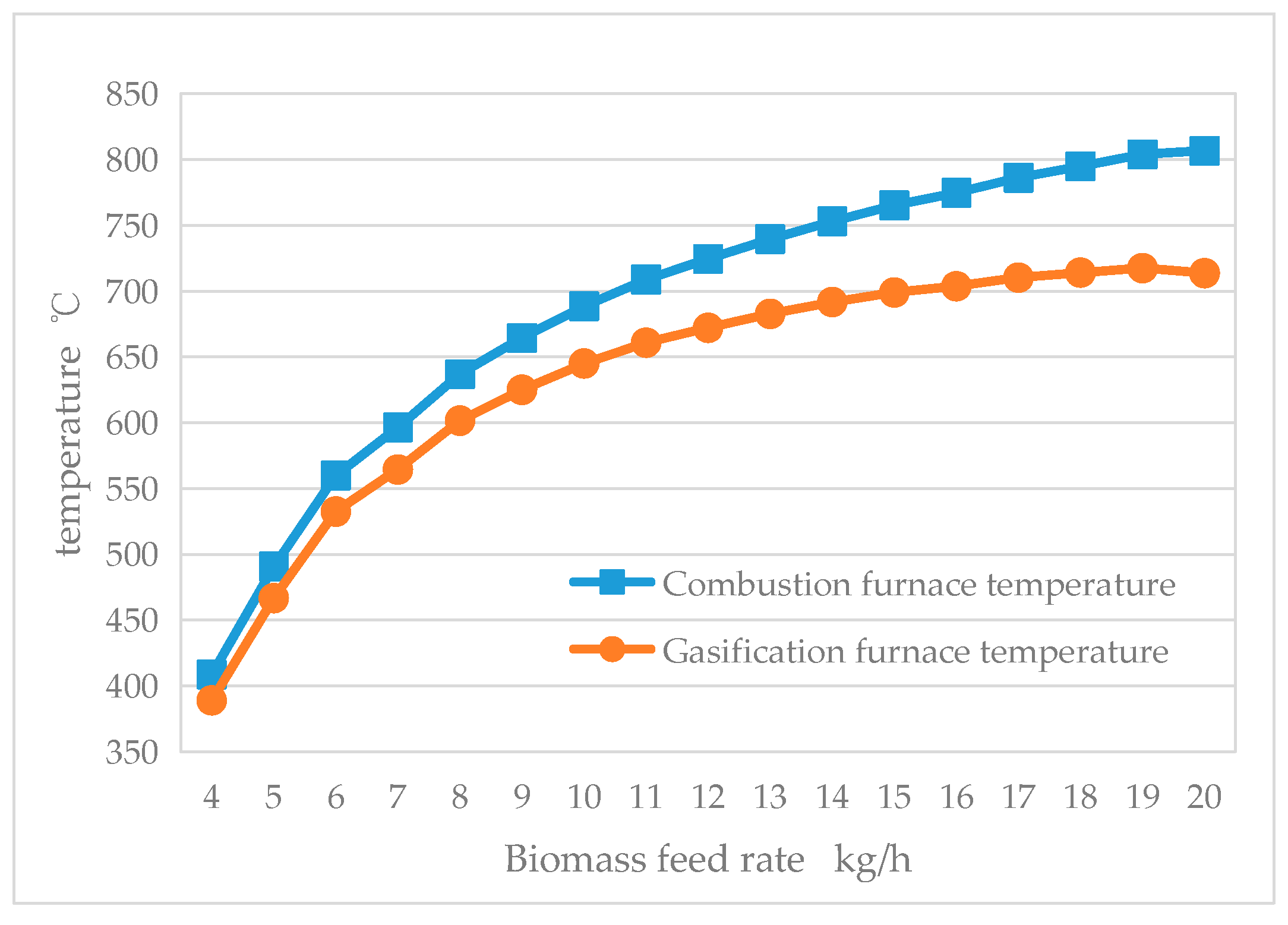
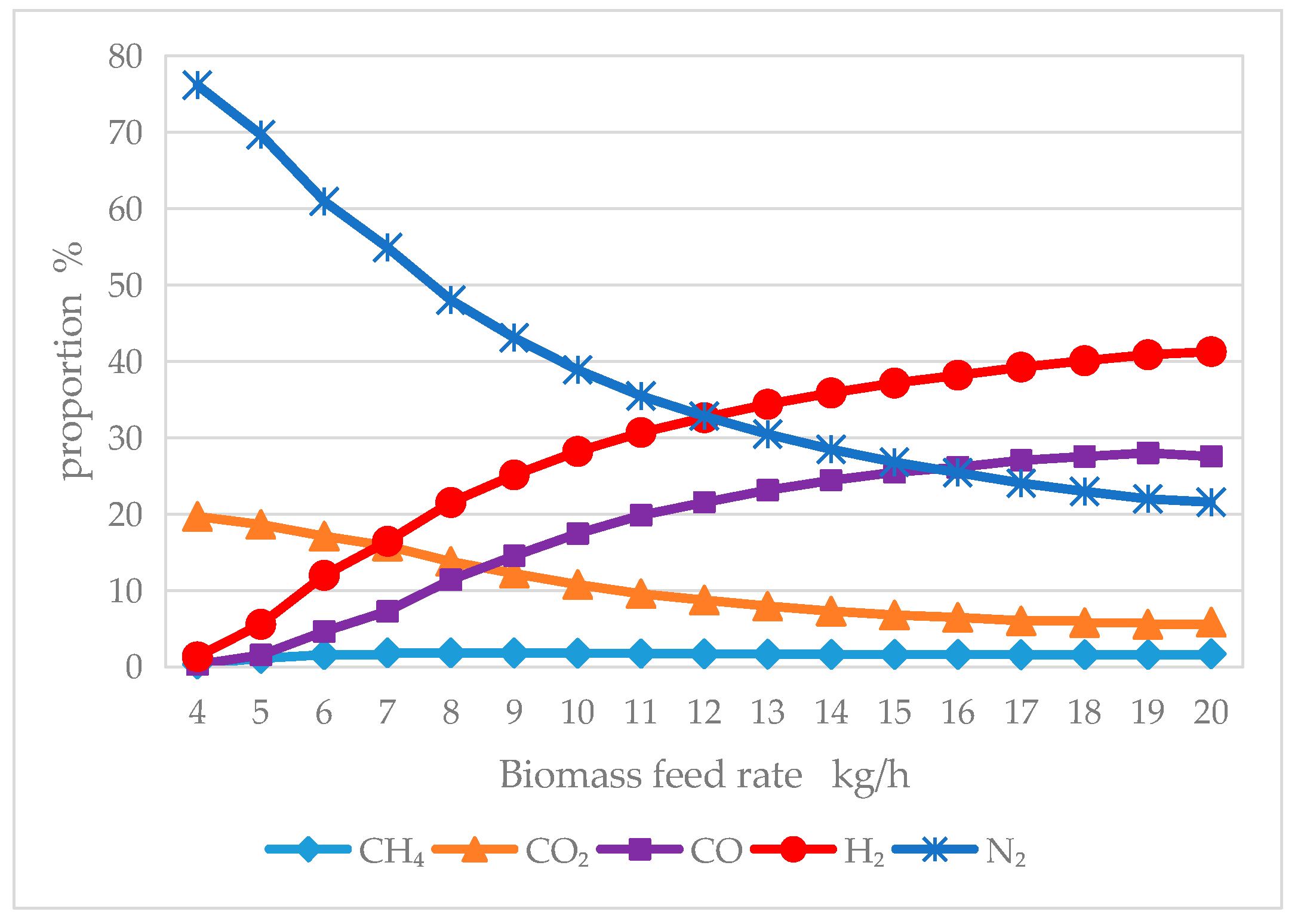
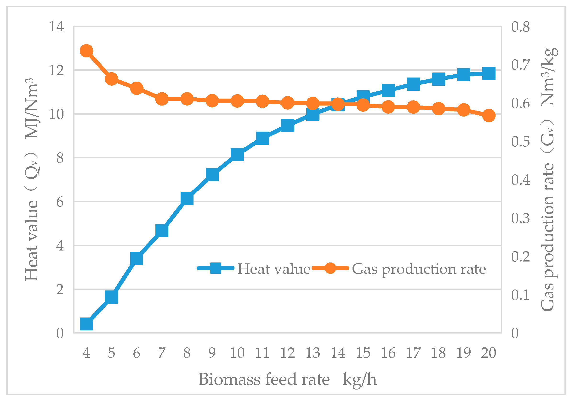
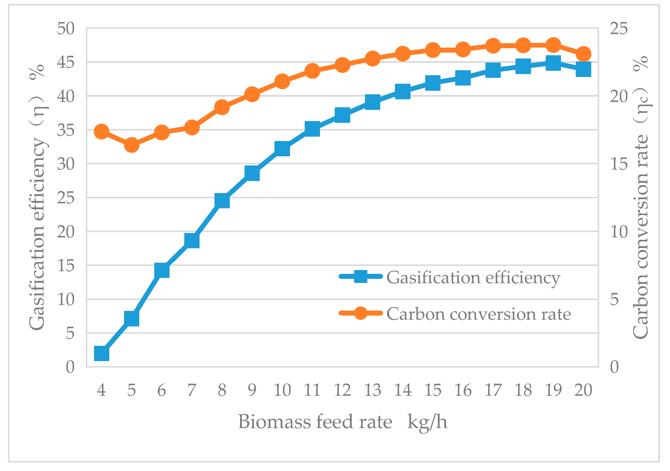
Under the conditions of a circulating bed material flow rate of 1800 kg/h, an air-to-fuel equivalent ratio (ER) of 0.1, and no steam input (0 kg/h), the sensitivity of changing the biomass feed rate on the reactor temperature, heating value QV, gas yield GV, carbon conversion rate ηc, and gasification efficiency η was simulated using the sensitivity analysis feature of the Aspen Plus software. The simulation results are presented in Figure 6, Figure 7, Figure 8 and Figure 9.
Under stable operating conditions, the dual-fluidized bed gasifier maintains a stable surface temperature, with the surface heat loss remaining at a relatively constant value. Therefore, the smaller the biomass feed rate, the larger the proportion of the surface heat loss. As can be seen from Figure 6, with the increase in biomass feed rate, the temperatures of the combustion furnace and gasification furnace gradually rise and tend to stabilize. A larger proportion of surface heat loss implies that a higher proportion of combustion air and more biomass feedstock are required to undergo combustion reactions to maintain the operating temperature of the gasifier reactor. This means that, the lower the feedstock gasification (pyrolysis) ratio, the higher the proportion of N2 in the gasification (pyrolysis) gas products, resulting in an increase in GV but a decrease in QV. It can be observed that, with the increase in biomass feed rate, QV gradually increases, GV gradually decreases, and both trends tend to level off and reach a stable state, with the η trend becoming increasingly higher and stabilizing.

3.2.2. The Impact of Circulating Bed Material Flow Rate

Under the conditions of a biomass feed rate of 8 kg/h, an air-to-fuel equivalent ratio (ER) of 0.1, and no steam addition (0 kg/h), the sensitivity of changing the circulating bed material flow rate on the reactor temperature, QV, GV, and η was simulated using the sensitivity analysis feature of the Aspen Plus software. The simulation results are presented in Figure 10, Figure 11, Figure 12 and Figure 13.
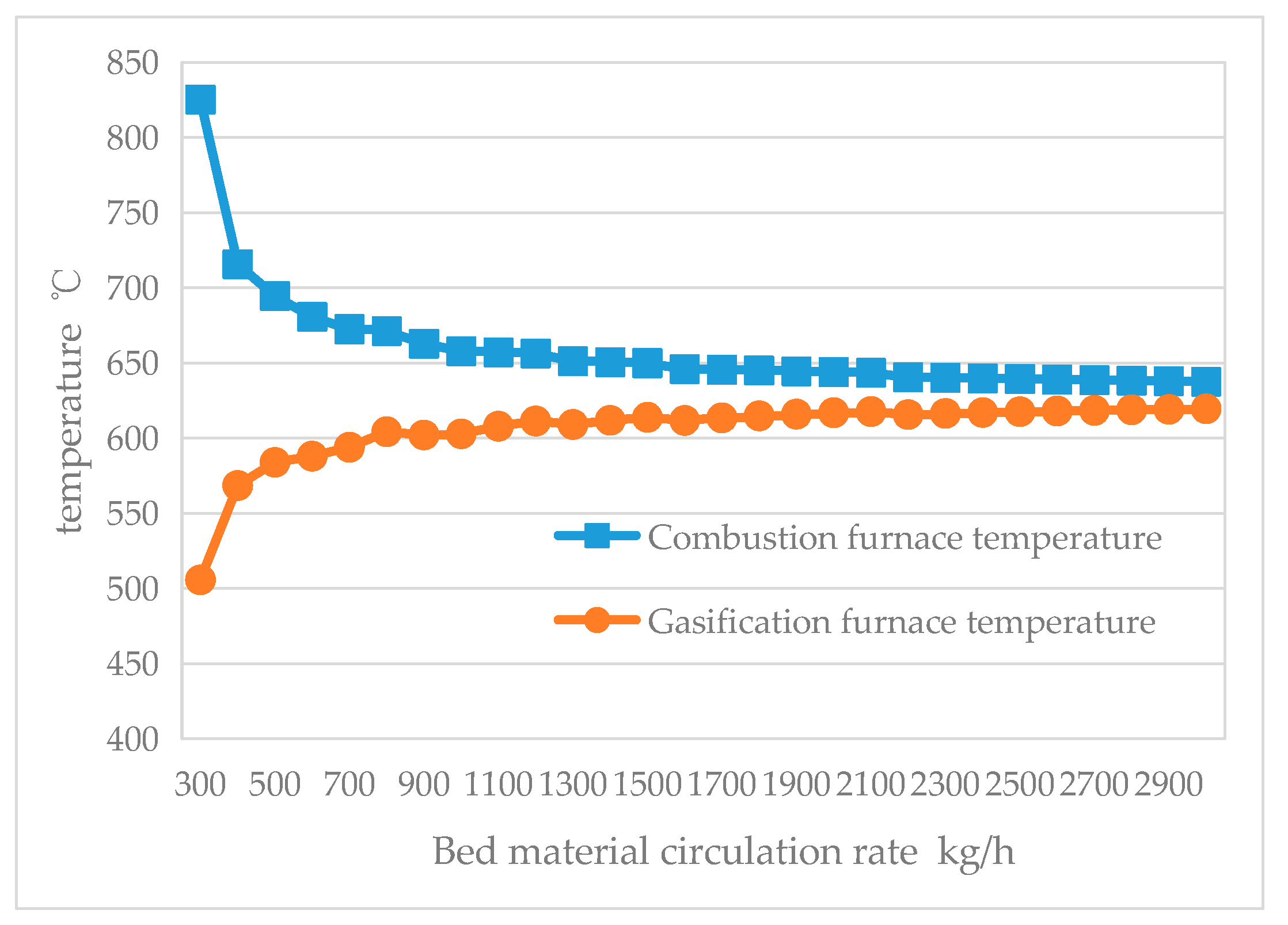
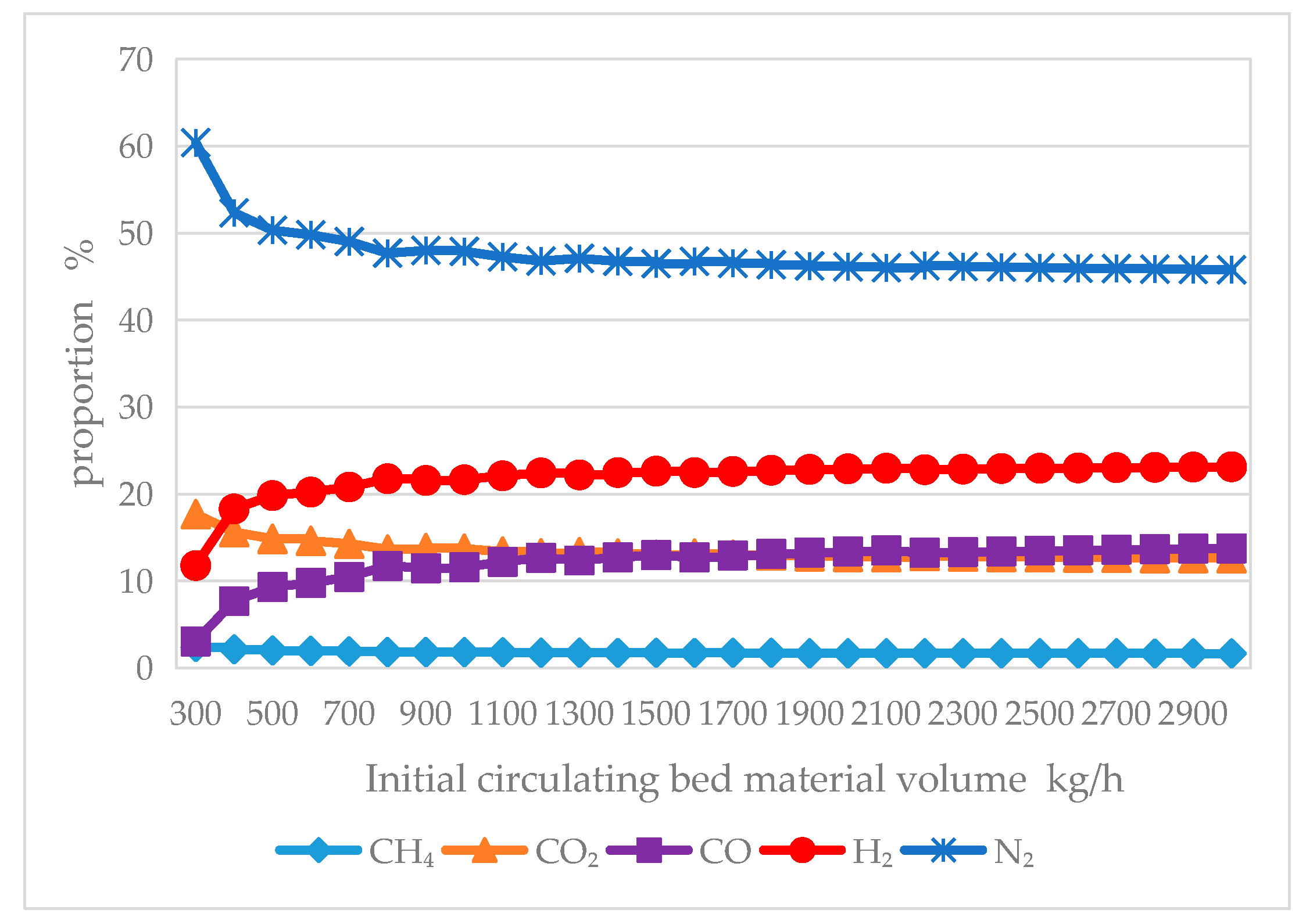
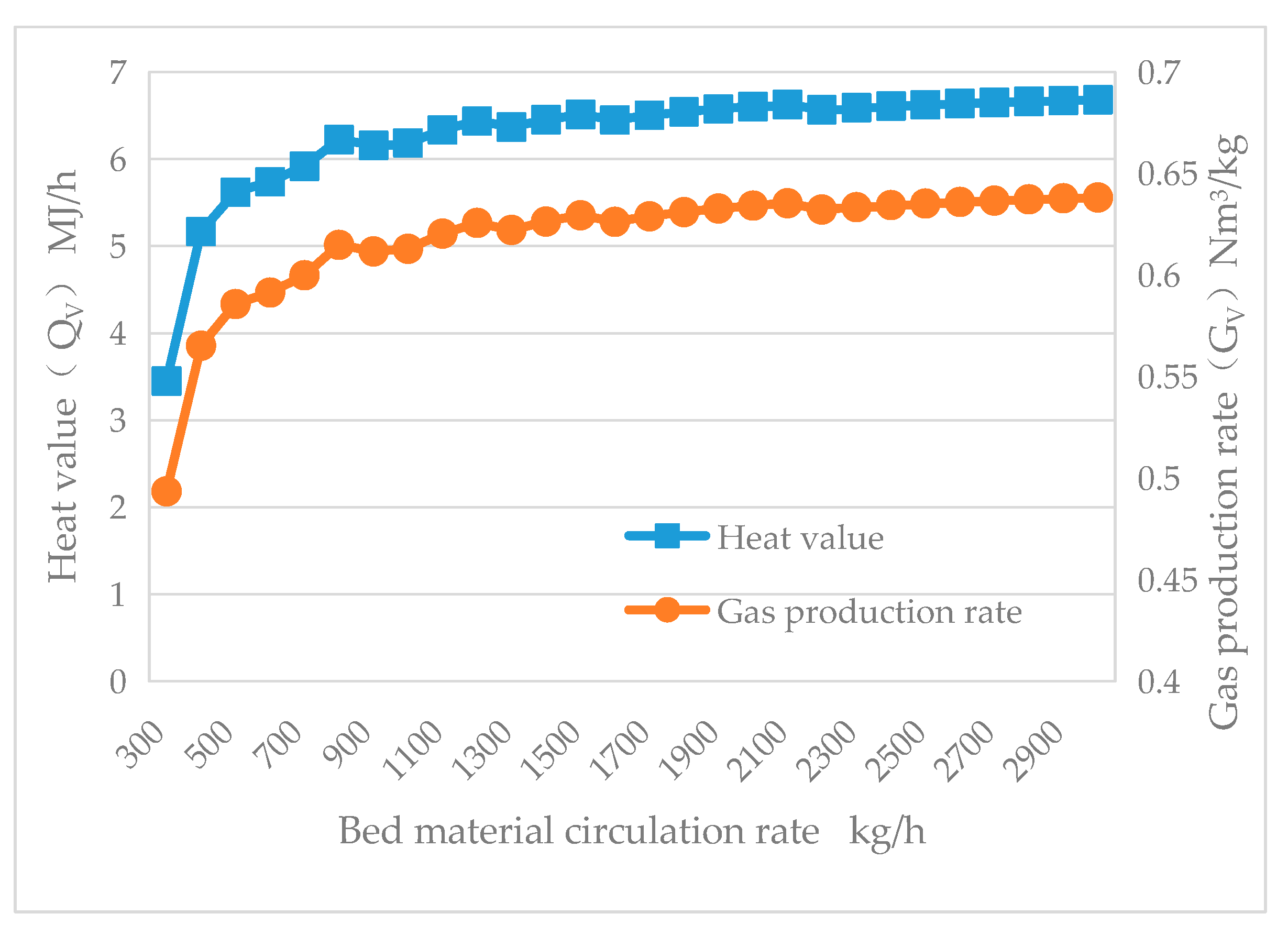
As shown in Figure 10, the temperature difference between the combustion furnace and the gasification furnace gradually decreases with the increase in the circulating bed material flow rate. Meanwhile, QV, GV, ηc, and η all gradually increase, as depicted in Figure 12 and Figure 13. This is because, the greater the circulating bed material flow rate, the higher the temperature of the gasification furnace, leading to more thorough pyrolysis of the biomass feedstock and the production of more gaseous components. Consequently, the fuel fraction entering the combustion furnace is reduced. However, after the circulating bed material flow rate exceeds 1300 kg/h, the trends of the various curves become increasingly stable, and the impact of the bed material flow rate decreases.

3.2.3. The Impact of Air-to-Fuel Equivalent Ratio (ER)

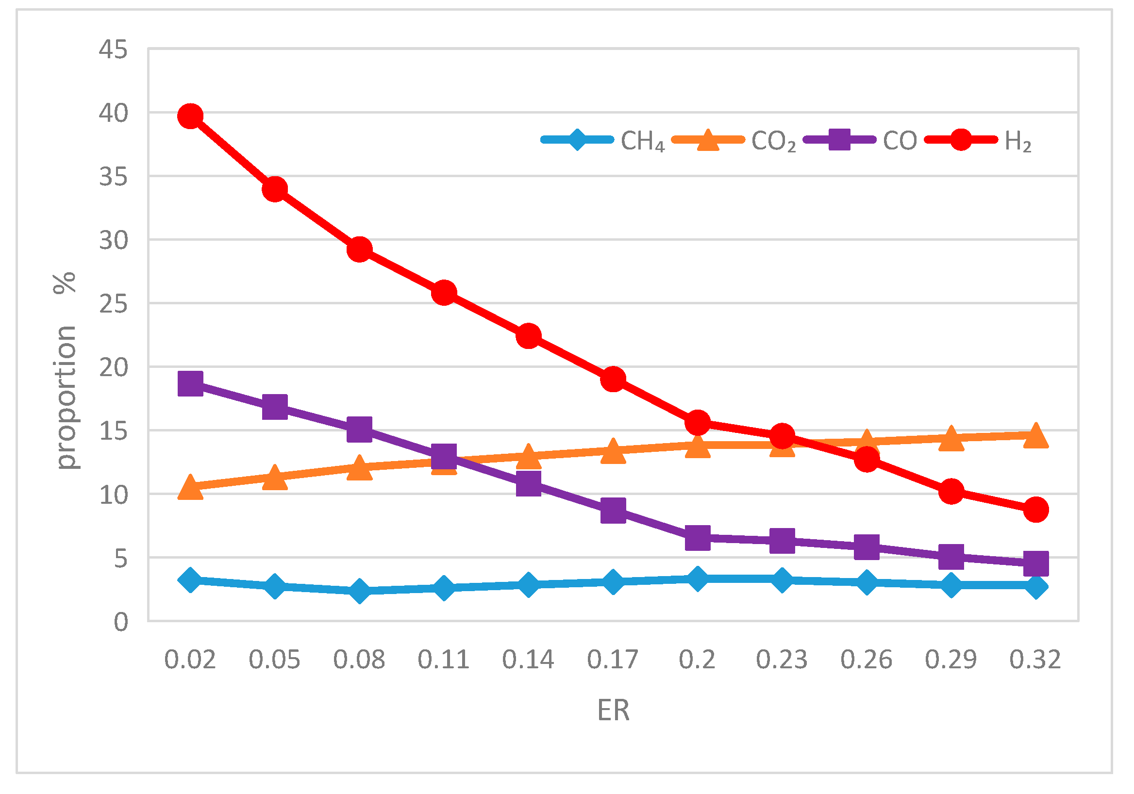
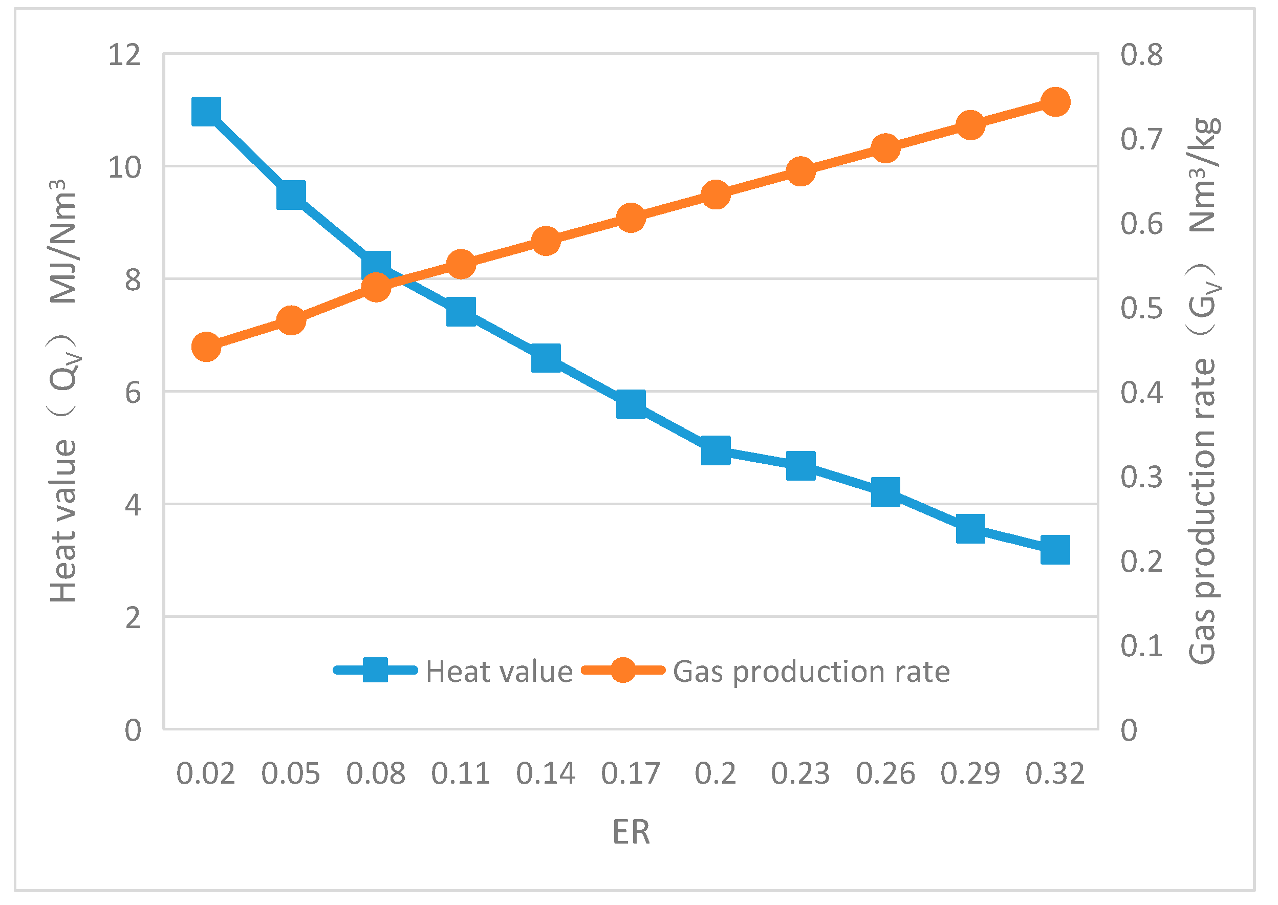
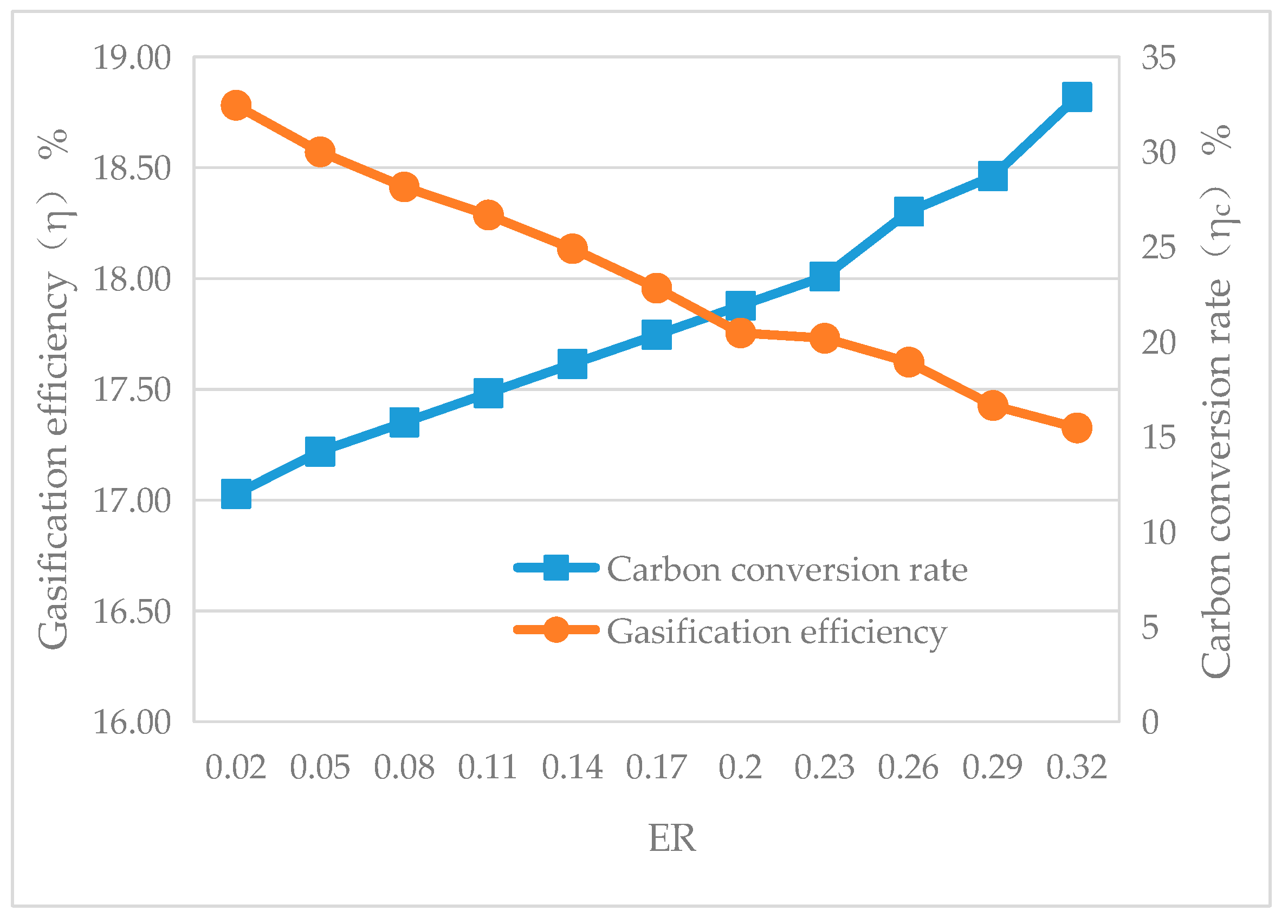
Under the conditions where the biomass feed rate is 8 kg/h, the circulating bed material flow rate is 1800 kg/h, and the S/B ratio is 0, the impact of changing the air-to-fuel equivalent ratio (ER) on the reactor temperature, QV, GV, and η was simulated using the sensitivity analysis feature of the Aspen Plus software. The change in the ER was achieved by adjusting the primary air flow rate to the gasification furnace. The simulation results are presented in Figure 14, Figure 15, Figure 16 and Figure 17.
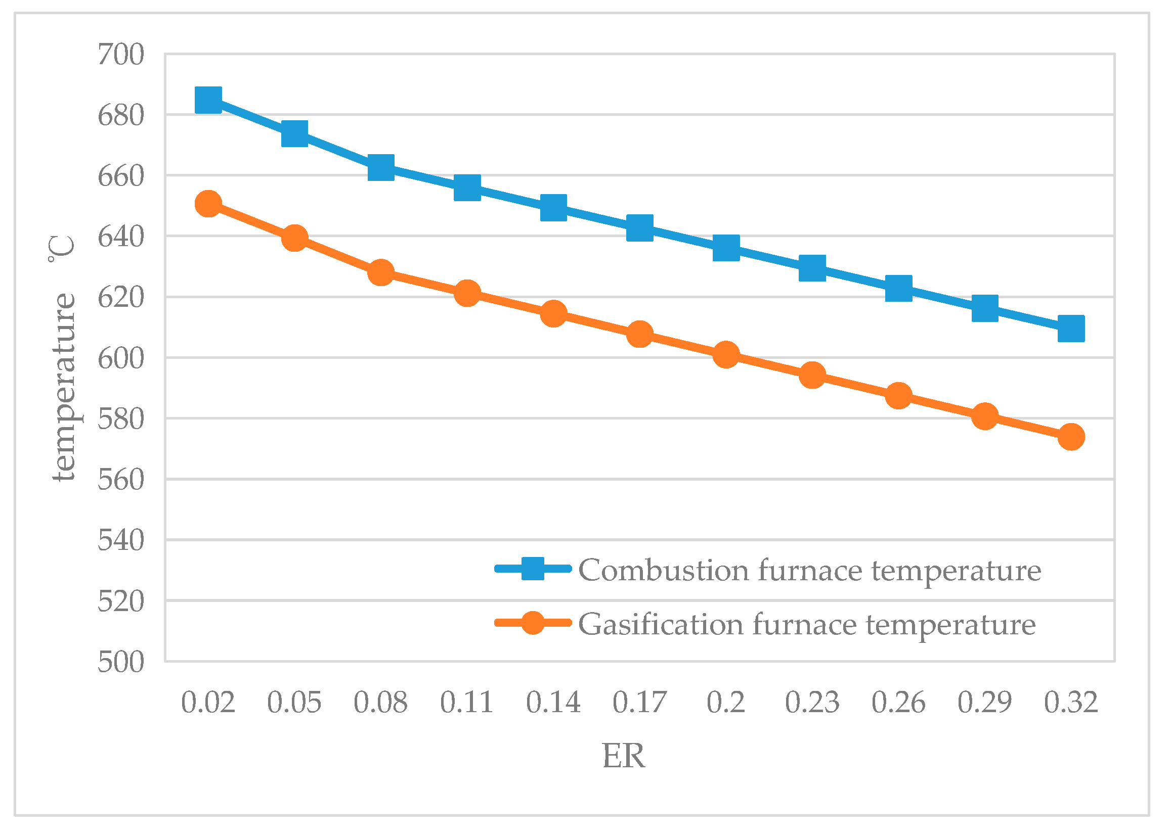
In a dual-fluidized bed gasification system, it is necessary to introduce a fluidizing medium from the bottom of the gasifier, which is usually air (or steam). On the one hand, it serves as a loosening medium to enhance the mobility of the bed materials. On the other hand, it can provide O2 or steam for a reaction with carbon in the semi-coke, thereby increasing the carbon conversion efficiency (ηc). As can be seen from Figure 14, the temperatures of both the combustor and the gasifier decrease with increasing ER. This is because, as the air flow rate at the bottom of the gasifier increases, the amount of semi-coke entering the combustor decreases, leading to an increase in ηc (as shown in Figure 17) and a reduction in the share of biomass used for combustion, resulting in a decrease in the overall furnace temperature. Meanwhile, the increase in the air flow rate at the bottom of the gasifier leads to an increase in the nitrogen content in the gas (as shown in Figure 15), which, although it improves GV, significantly reduces QV, as shown in Figure 16. Overall, the efficiency η still decreases, as shown in Figure 17.

3.2.4. The Impact of Steam-to-Biomass Ratio (S/B)

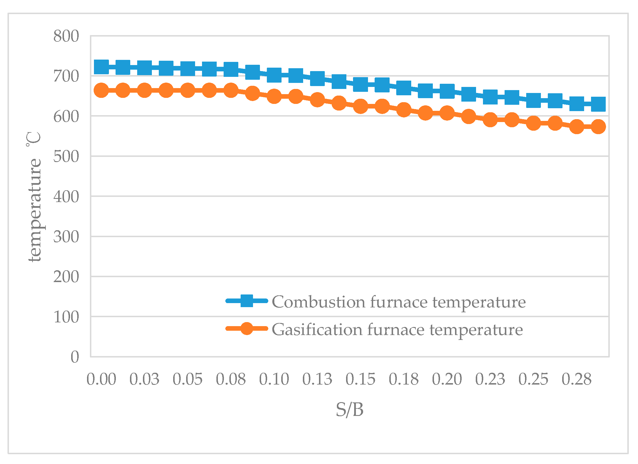
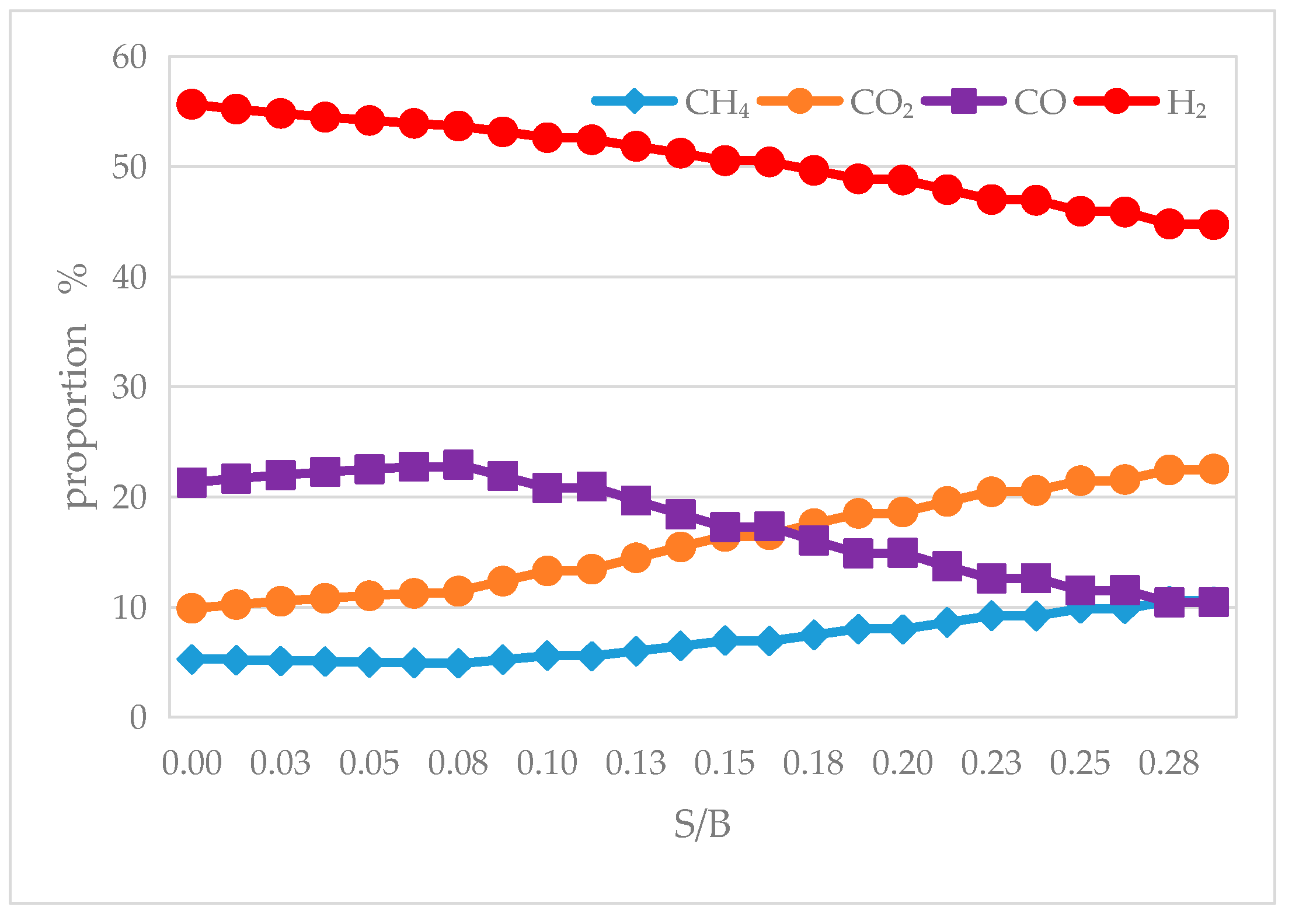
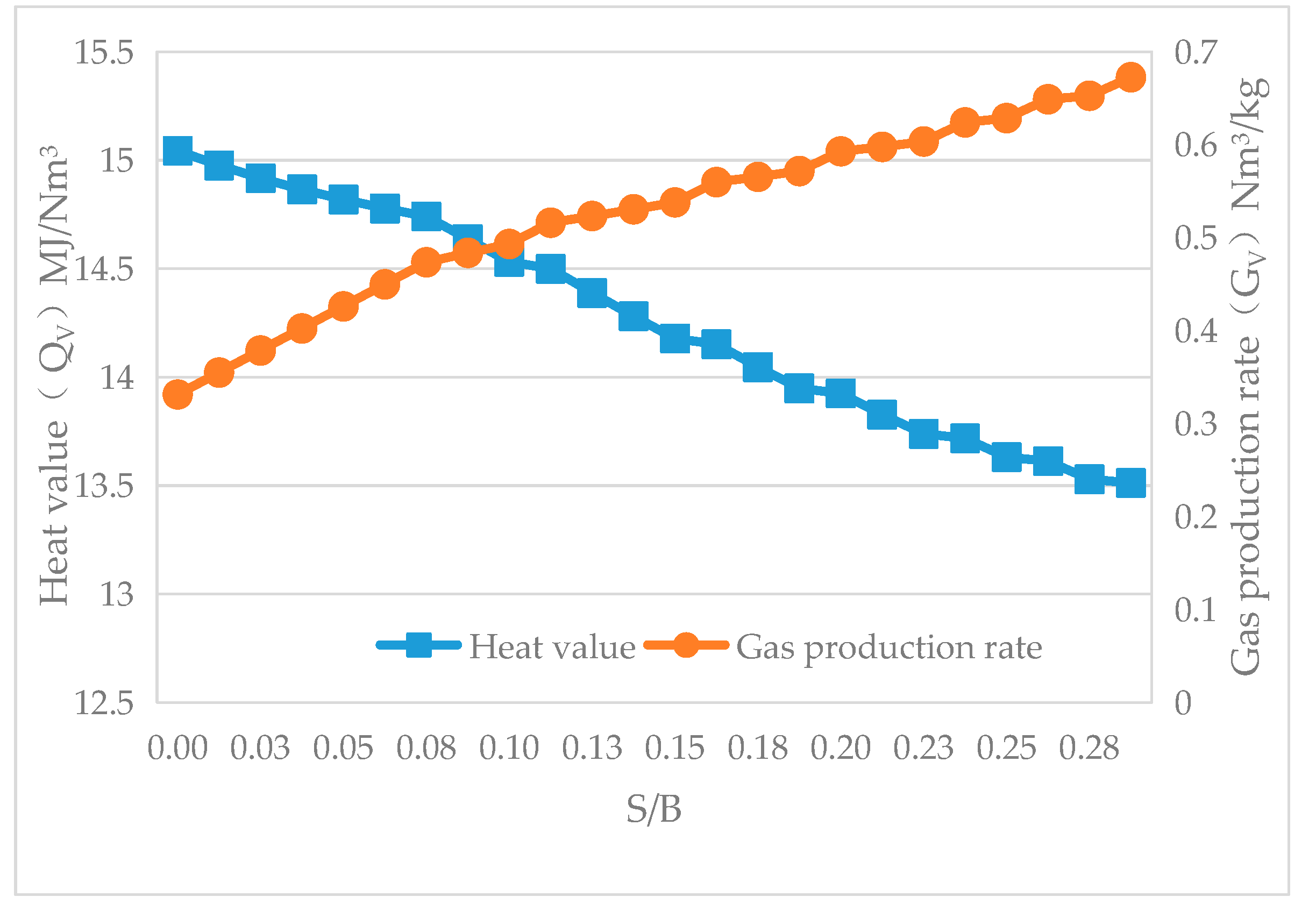
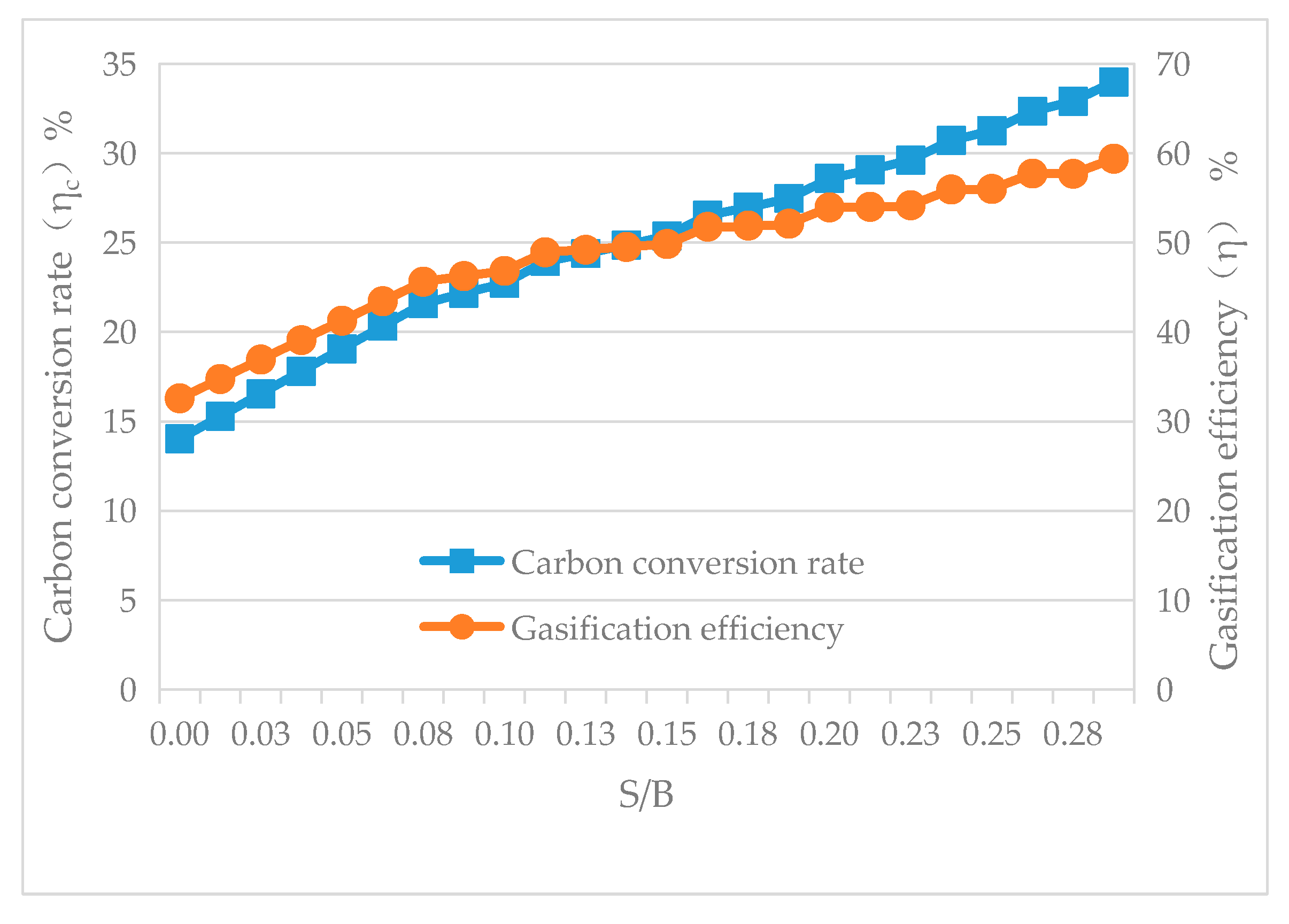
Under the conditions where the biomass feed rate is 8 kg/h and the circulating bed material flow rate is 1800 kg/h, the impact of changing the steam-to-biomass ratio (S/B) on the reactor temperature, QV, GV, and η was simulated using the sensitivity analysis feature of the Aspen Plus software. The simulation results are presented in Figure 18, Figure 19, Figure 20 and Figure 21.
Changing the primary air at the bottom of the gasifier to steam has a relatively small impact on the furnace temperature, gas composition, and QV. The dual-fluidized bed gasifier operates stably, and the gas quality is consistent, as shown in Figure 18, Figure 19 and Figure 20. However, due to the reaction between steam and semi-coke according to Equation (3) in the semi-coke gasification module, there is a significant increase in GV, ηc, and η, as shown in Figure 20 and Figure 21.

3.2.5. The Impact of Adding a Catalyst

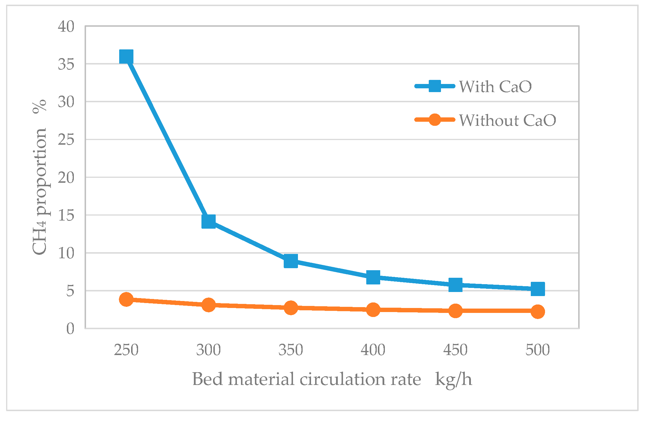
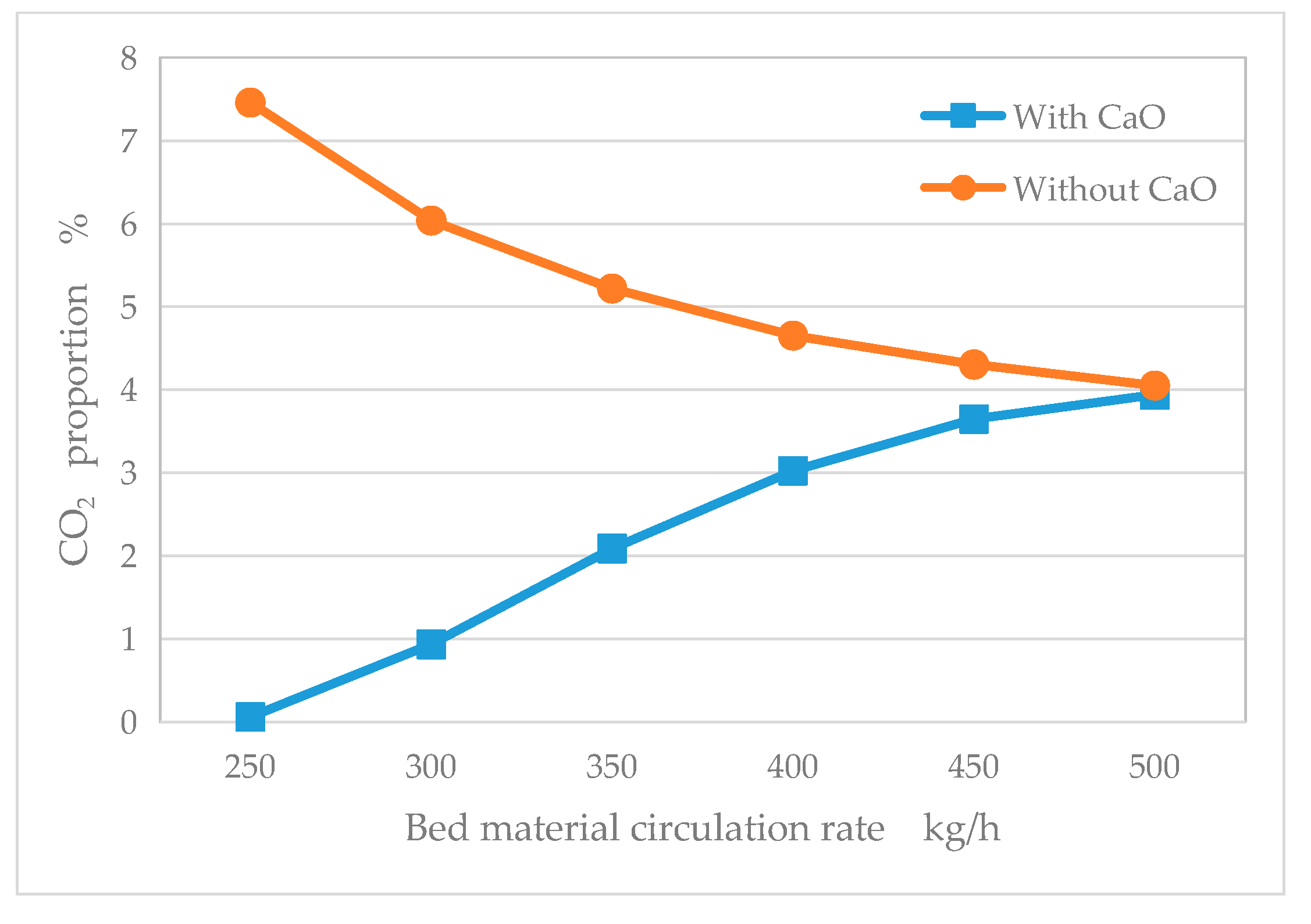
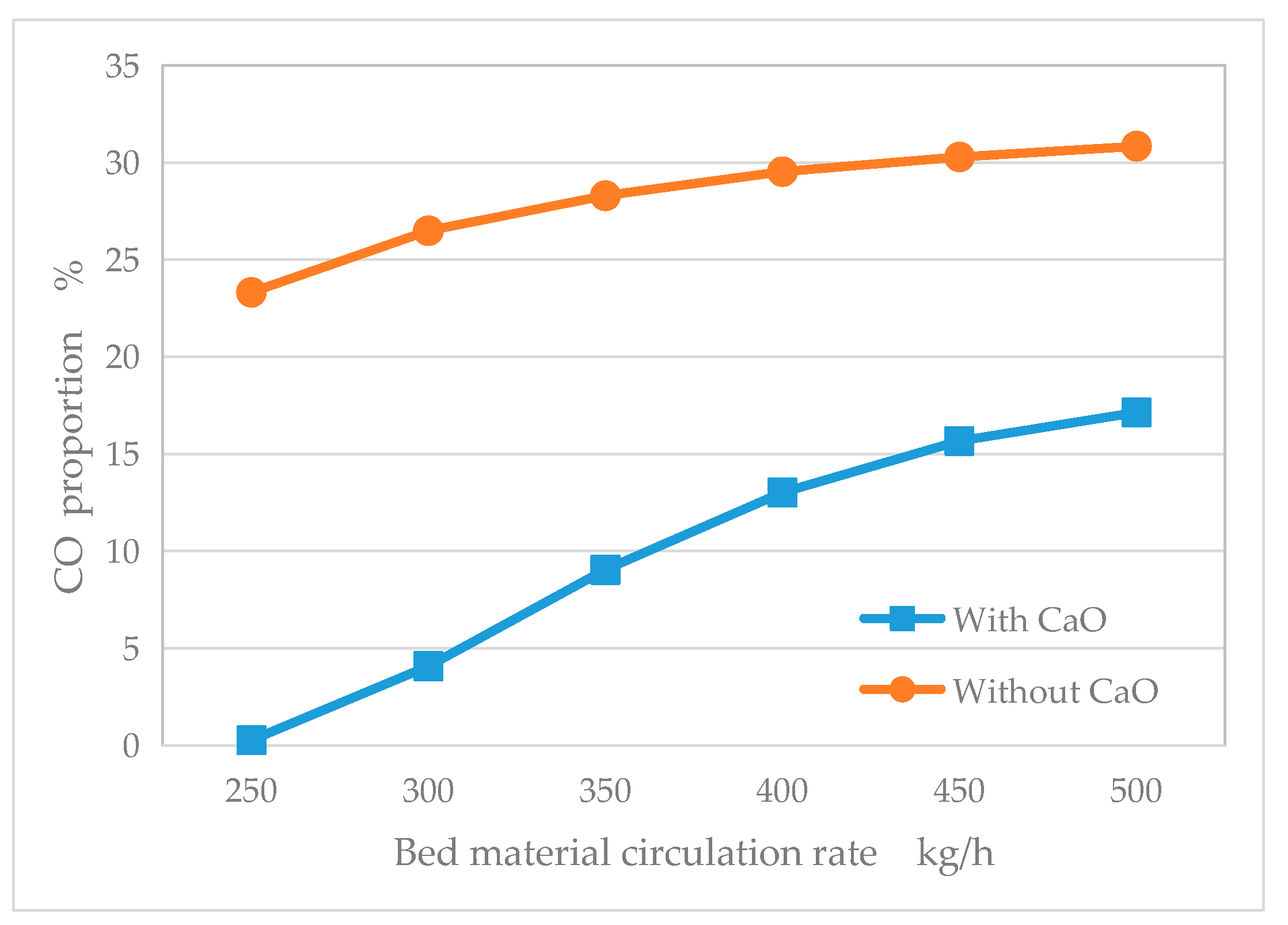
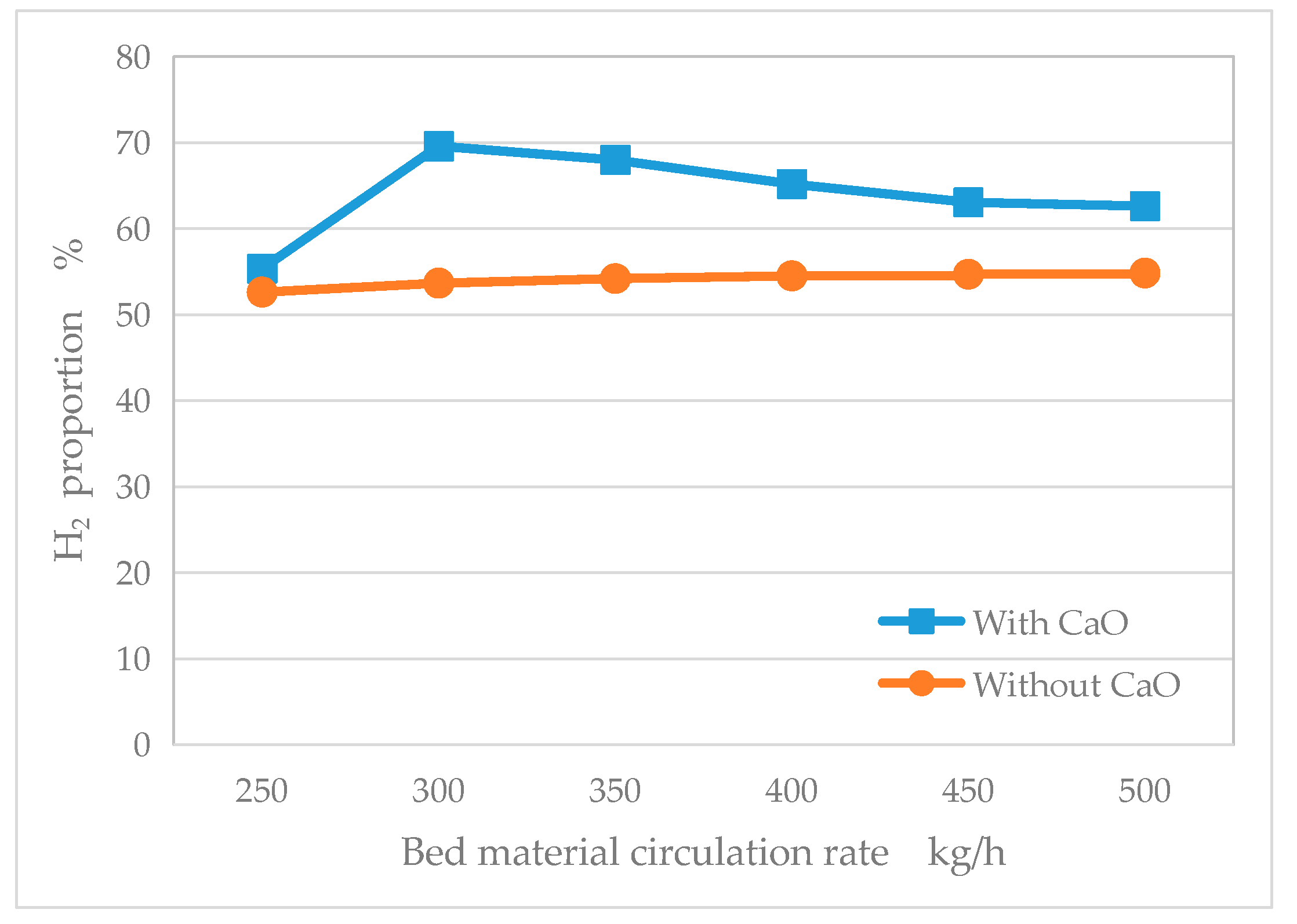
Due to the assumption in the simulation calculation that all the tar is converted, only the influence of CaO in the catalyst on the gasification characteristics is considered. Under the conditions of a biomass feed rate of 8 kg/h, the addition of quicklime at 5 kg/h, a convergence tolerance of 0.005, and a primary air flow of 0 for the gasifier, the rules of variation for the gas composition and QV, GV, ηc, and η with the addition of CaO at different reactor temperatures were investigated. The flow and reaction of the CaO within the dual-bed system are primarily influenced by the temperature difference between the combustion furnace and the gasification furnace, including the conversion between CaO and CaCO3 as well as the accompanying endothermic and exothermic reactions. This section creates different temperature differences (different gasifier temperatures) between the combustion furnace and the gasification furnace by varying the circulating bed material flow in order to study the cyclic characteristics of CaCO3 and the rules of variation for gas quality under different temperature differences (different gasifier temperatures). The results are shown in Figure 22, Figure 23, Figure 24, Figure 25, Figure 26 and Figure 27.
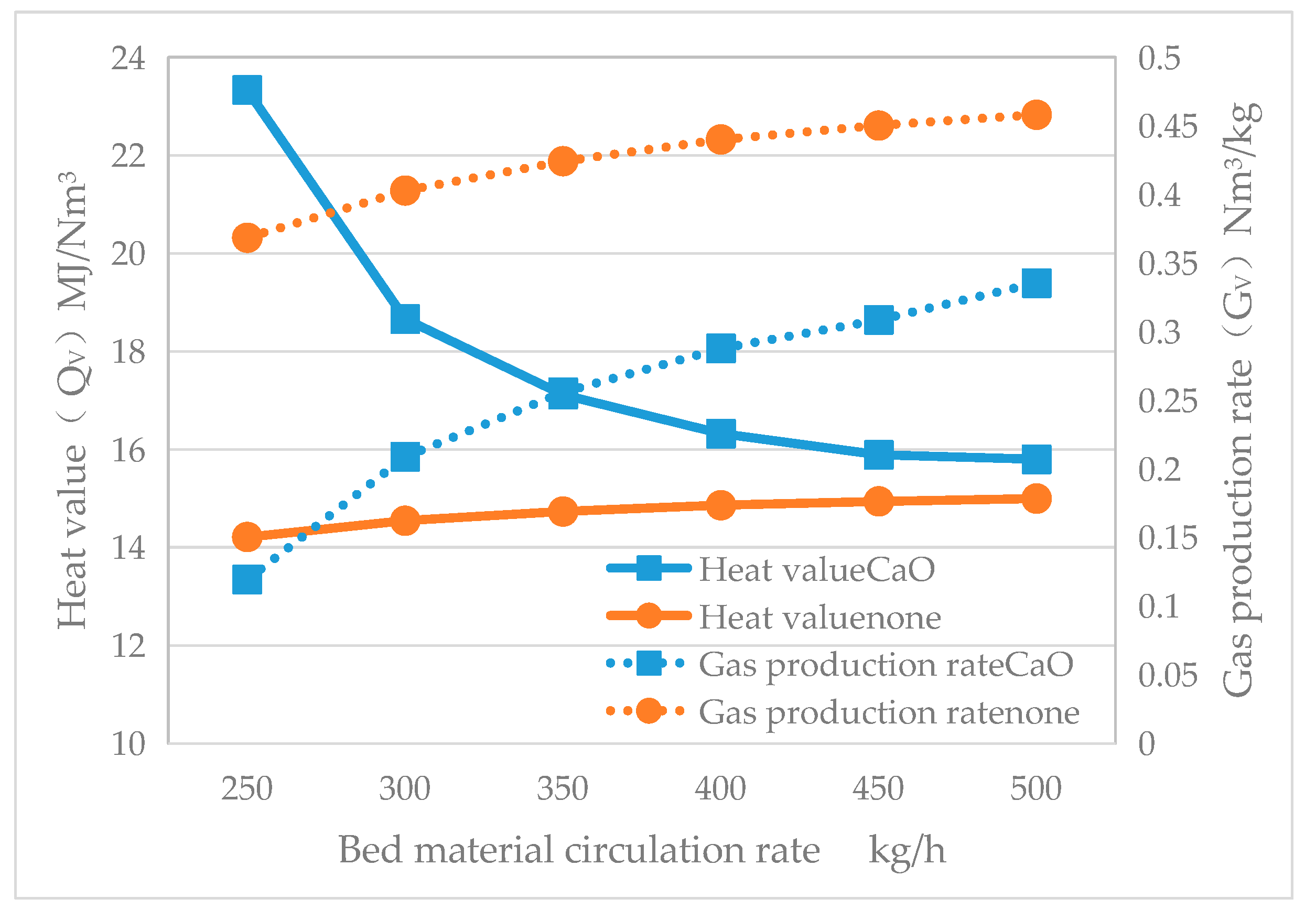
As shown in Figure 22, Figure 23, Figure 24, Figure 25 and Figure 26, after the addition of CaO, both the ϕCO and ϕCO2 levels are reduced compared to when CaO is not added, with a significant decrease in ϕCO2; the contents of ϕCH4 and ϕH2 are both significantly increased, and the QV is higher when CaO is added. Furthermore, as can be seen from Figure 26, after the addition of CaO, the QV gradually decreases with the increase in the circulating bed material flow and eventually becomes consistent with the results without the CaO addition. This is because the reaction of CaO converting to CaCO3 is an exothermic reaction, and the increase in the circulating bed material flow leads to a higher gasification furnace temperature (as detailed in Figure 27), which thereby hinders the progress of the CaO and CO2 reaction.
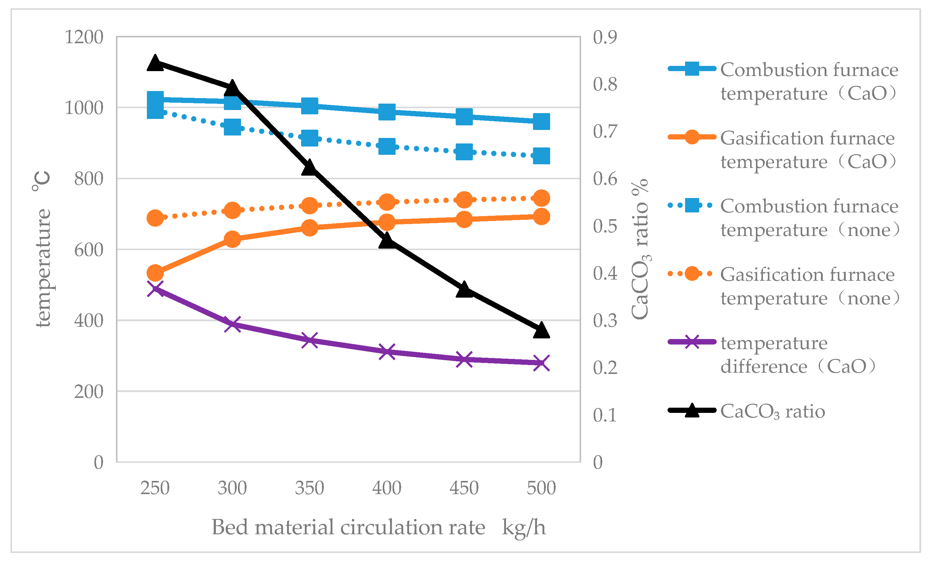
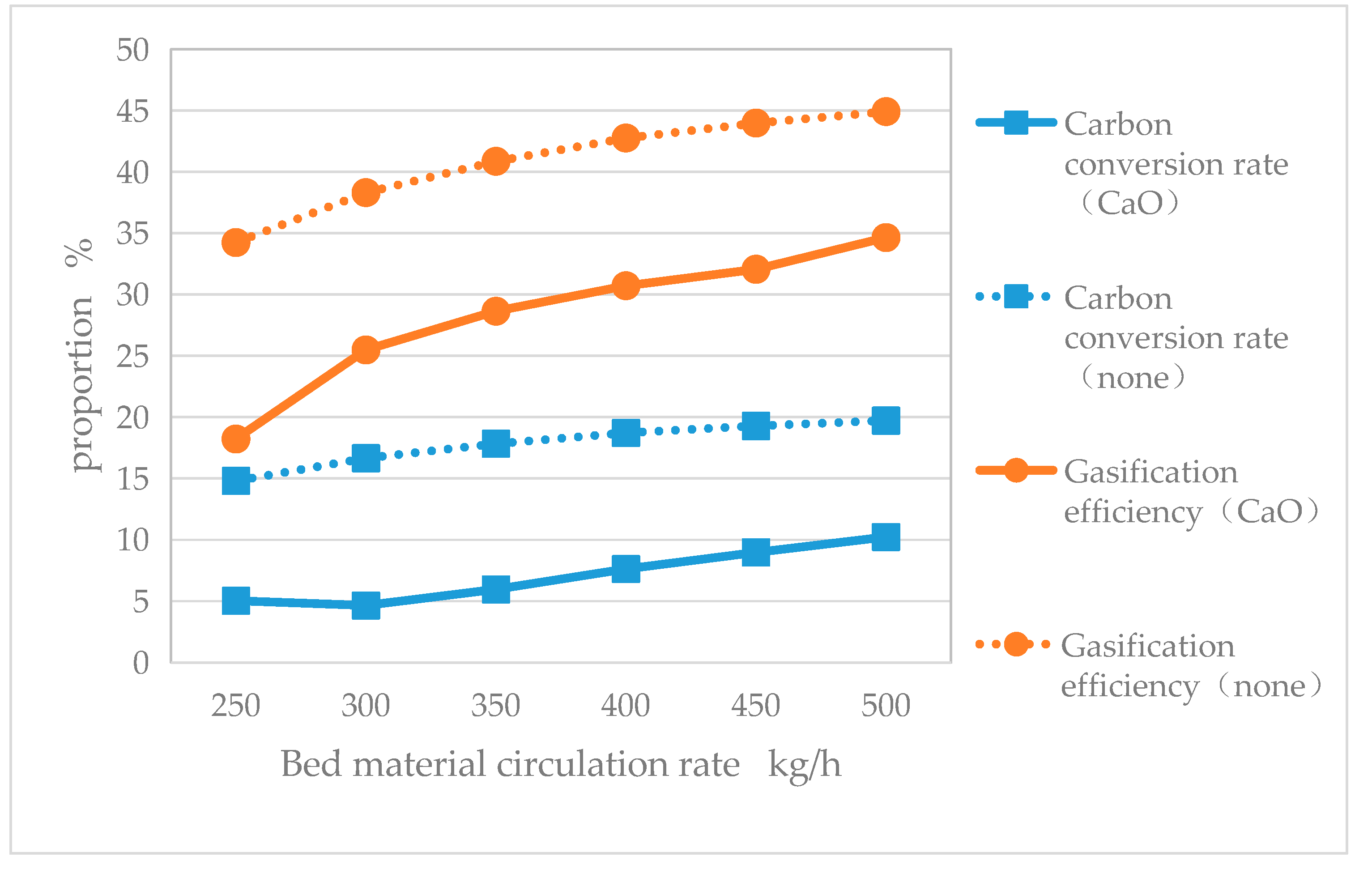
As shown in Figure 27, as the amount of circulating bed material increases, the temperature of the combustion furnace gradually decreases while the temperature of the gasification furnace gradually increases. Under the conditions with CaO added, the temperature difference between the combustion furnace and the gasification furnace is greater. As the temperature difference between the combustion furnace and the gasification furnace decreases (the temperature of the gasification furnace increases), the proportion of CaCO3 formed by the reaction in the gasification furnace out of the total moles of calcium decreases gradually. This indicates that a larger temperature difference between the combustion furnace and the gasification furnace (lower temperature in the gasification furnace) is favorable for the progress of the CaO and CO2 reaction. It is beneficial for obtaining gas with a higher calorific value, but the gas production rate GV decreases, as shown in Figure 26. At the same time, as shown in Figure 28, the carbon conversion efficiency ηc and the gasification efficiency η are also lower when CaO is added compared to when it is not added. This requires achieving the optimal operating conditions between the gas calorific value (QV), gas yield (GV), carbon conversion rate (ηc), and gasification efficiency (η) through the control of the process parameters during the actual engineering operation of the dual-fluidized bed gasification system in order to maximize the benefits.
After all, the dual-fluidized bed reactor has two high-temperature exhaust channels, so the low thermal efficiency and carbon conversion rate of the dual-fluidized bed reactor itself lead to its low economic efficiency. The reactor itself should be placed in specific application scenarios to form a comprehensive system for more rational energy utilization. In recent years, the field of the green chemical industry using biomass as a raw material has received a great deal of attention [23,24]. When CaO is used as the circulating bed material, the dual-fluidized bed gasification process of biomass can form a calcium cycle chemical chain system, which has broad prospects in the application fields of producing hydrogen-rich gas and synthesizing green methanol from biomass as raw material: preparing hydrogen-rich synthesis gas in the gasifier, and adjusting the operating parameters to make the hydrogen carbon ratio of the synthesis gas reach a level suitable for methanol preparation. The energy consumption of the compressor required by the downstream methanol synthesis unit can be driven by the steam turbine on the combustion side, forming a reasonable green chemical production and energy cascade utilization system as a whole.

4. Conclusions

A thermodynamic calculation model of the dual-fluidized bed biomass gasification process was established using the Aspen Plus software, incorporating modules such as the RGibbs reactor, yield reactor RYield, component separator Sep, and SSSplit. The model comprehensively reflects the variations and characteristics regarding the furnace temperature and gas quality during the bed material circulation process. It examines the influence of different process parameters on the operation of the dual-fluidized bed gasification system and the quality of the produced gas. Additionally, the model studies the regularity of the impact of adding CaO on the gas quality of the dual-fluidized bed system.
(1) The fuel feed rate and circulating bed material quantity are positively correlated with QV, ηc, and η; ER is positively correlated with GV and ηc and negatively correlated with QV and η; S/B is positively correlated with GV, ηc, and η and negatively correlated with QV.
(2) The addition of CaO is beneficial for increasing QV. In the actual operation process, a lower reaction temperature in the gasification bed can be achieved by reducing the circulating bed material quantity, which increases the temperature difference between the combustion furnace and the gasification furnace, contributing to the improved quality of the produced gas. At the same time, it is necessary to consider GV, ηc, and η in seeking the optimal operating conditions to maximize the benefits.
(3) The simulation results of this model, when compared with the experimental measured data, show numerical values and trends that are similar, which validates the reliability of the model. Through the sensitivity analysis, the model investigates the influence of different process parameters on the operational characteristics and gas quality, providing certain guidance for engineering practice. In this study, the fluctuation trends of parameters such as reaction temperature, gas production components, calorific value QV, gasification efficiency η, and carbon conversion rate ηc tended to stabilize after the feed rate exceeded 15 kg/h and tended to stabilize after the bed material circulation rate exceeded 1100 kg/h. A too-small feeding rate and bed material circulation rate are not conducive to the stability of the system’s operating parameters. An increase in the ER has a negative impact on key indicators such as temperature, H2 and CO volume content, calorific value QV, and gasification efficiency η. Therefore, while maintaining the normal fluidization of the gasification reactor, it is important to try to reduce the ER value as much as possible. An increase in the S/B can increase the volume content of CO and CH4, gasification efficiency η, and carbon conversion rate ηc. However, an excessively high S/B will increase the CO2 content, reduce the calorific value QV, and consume more energy. The most suitable S/B in this study should be around 0.08.
(4) This model uses the RGIBBS reactor, which is a thermodynamic equilibrium calculation model, to study the ideal steady-state conditions after a complete reaction. Due to the limitations of the dynamics in actual operation and the neglect of tar in this model, there is a certain degree of difference between the simulation results and actual operation results. The future work directions include fully considering the important impact of tar on fuel gas generation, investigating the coupling of the gas–solid reaction kinetics and solid particle fluid dynamics in the reactor, achieving a more detailed description of the internal operating characteristics of the reactor, and improving the accuracy of the simulation results, as well as conducting simulation calculations on the energy flow, logistics, and carbon footprint for large-scale dual-fluidized bed chemical chain hydrogen production systems. It is important to explore the feasibility of combining dual-fluidized bed equipment with waste heat recovery systems, power generation systems, carbon capture and recycling systems, etc., to further improve the overall energy utilization efficiency of the system and reduce the production cost of the overall process. Integrating chemical chain hydrogen production systems with chemical energy storage systems such as green methanol and green ammonia, as well as downstream hydrogen utilization end systems such as fuel cells, will be beneficial in terms of exploring the application scenarios of dual-fluidized bed biomass gasification in the hydrogen energy industry.

Author Contributions

Conceptualization, L.Y.; methodology, L.Y.; validation, J.Z.; formal analysis, J.Z. and L.Y.; investigation, J.Z. and L.Y.; data curation, J.Z. and L.Y.; writing—original draft preparation, L.Y.; writing—review and editing, J.Z.; visualization, L.Y.; All authors have read and agreed to the published version of the manuscript.

Funding

This work was funded by the project with contract number 2023-JZSZ-ZB-007-FB-001, and by the project with project number 2022TSGC1031.

Data Availability Statement

The original contributions presented in the study are included in the article, further inquiries can be directed to the corresponding author.

Acknowledgments

Special thanks to Junhui Yang, Xiaoxu Fan, and Sheng Li for their contributions to the publication of the paper.

Conflicts of Interest

Author Jida Zhang was employed by the company China Coal (Tianjin) Underground Engineering Intelligent Research Institute Co., Ltd. The remaining authors declare that the research was conducted in the absence of any commercial or financial relationships that could be construed as a potential conflict of interest.

References

  1. Song, G.; Lv, Q.; Liu, Q. Experimental Research on Coal Gasification Characteristics in Single and Dual Circulating Fluidized Beds. Proc. CSEE 2009, 29, 24–29. [Google Scholar]
  2. Abuelgasim, S.; Wang, W.; Abdalazeez, A.A. brief review for chemical looping combustion as a promising CO2 capture technology: Fundamentals and progress. Sci. Total Environ. 2021, 764, 142892. [Google Scholar] [CrossRef] [PubMed]
  3. Alalwan, H.A.; Alminshid, A.H. CO2 capturing methods: Chemical looping combustion (CLC) as a promising technique. Sci. Total Environ. 2021, 788, 147850. [Google Scholar] [CrossRef] [PubMed]
  4. Nguyen, N.M.; Alobaid, F.; Dieringer, P. Biomass-based chemical looping gasification: Overview and recent developments. Appl. Sci. 2021, 11, 7069. [Google Scholar] [CrossRef]
  5. Lin, Y.; Wang, H.; Wang, Y. Review of biomass chemical looping gasification in China. Energy Fuels 2020, 34, 7847–7862. [Google Scholar] [CrossRef]
  6. Goel, A.; Moghaddam, E.M.; Liu, W. Biomass chemical looping gasification for high-quality syngas: A critical review and technological outlooks. Energy Convers. Manag. 2022, 268, 116020. [Google Scholar] [CrossRef]
  7. Samprón, I.; de Diego, L.F.; García-Labiano, F. Biomass Chemical Looping Gasification of pine wood using a synthetic Fe2O3/Al2O3 oxygen carrier in a continuous unit. Bioresour. Technol. 2020, 316, 123908. [Google Scholar] [CrossRef] [PubMed]
  8. Hu, Q.; Shen, Y.; Chew, J.W. Chemical looping gasification of biomass with Fe2O3/CaO as the oxygen carrier for hydrogen-enriched syngas production. Chem. Eng. J. 2020, 379, 122346. [Google Scholar] [CrossRef]
  9. Bassano, C.; Deiana, P.; Pacetti, L. Integration of SNG plants with carbon capture and storage technologies modeling. Fuel 2015, 161, 355–363. [Google Scholar] [CrossRef]
  10. Yu, B.; Chien, I. Design and economic evaluation of a coal-based polygeneration process to coproduce synthetic natural gas and ammonia. Ind. Eng. Chem. Res. 2015, 54, 10073–10087. [Google Scholar] [CrossRef]
  11. Ye, C.; Zheng, Y.; Xu, Y. Energy and exergy analysis of poly-generation system of hydrogen and electricity via coal partial gasification. Comput. Chem. Eng. 2020, 141, 106911. [Google Scholar] [CrossRef]
  12. Guan, H.; Fan, X.; Zhao, B. An experimental investigation on biogases production from Chinese herb residues based on dual circulating flfluidized bed. Int. Hydrog. Energy 2018, 43, 12618–12626. [Google Scholar] [CrossRef]
  13. Zhou, X.; Yang, L.; Fan, X. Experimental Study on the Preparation of Hydrogen Rich Gas by Gasifying of Traditional Chinese Medicine Residue in a Dual Fluidized Bed Based on Calcium Looping. Energies 2023, 16, 4434. [Google Scholar] [CrossRef]
  14. Aspen Plus. Getting Started Modeling Processes with Solids[R/OL]; Aspen Technology: Cambridge, UK, 2000. [Google Scholar]
  15. Wright, M.; Satrio, J.; Brown, R. Techno-Economic Analysis of Biomass Fast Pyrolysis to Transportation Fuels; NREL/TP-6A20-46586[R]; US Department of Energy Office of Scientific and Technical Information: Oak Ridge, TN, USA, 2010. [Google Scholar]
  16. Hu, J.; Zeng, D.; Cui, D. Simulation of Lignite Chemical-looping Gasification Using Combined Fe-Cu Oxides as Oxygen Carrier. Ind. Control Comput. 2020, 33, 94–96. [Google Scholar]
  17. Jin, Z.; Jin, B. Numerical Simulation of Chemical Chain Combustion Based on Aspen Plus. Ind. Control Comput. 2019, 32, 116–117. [Google Scholar]
  18. Wang, L.; Song, T.; Zhang, J. Simulation of chemical looping gasification of high-sulfur petroleum coke for syngas production coupled with recycling sulfur in 10 MWth system. CIESC J. 2019, 70, 2279–2288. [Google Scholar]
  19. Kathe, M.V.; Empfield, A.; Na, J.; Blair, E.; Fan, L.S. Hydrogen production from natural gas using an iron-based chemical looping technology: Thermodynamic simulations and process system analysis. Appl. Energy 2016, 165, 183–201. [Google Scholar] [CrossRef]
  20. Rosario, P.; Graeme, W.; Raffaella, O. Techno-economic investigation of a chemical looping combustion based power plant. Faraday Discuss. 2016, 192, 437–457. [Google Scholar]
  21. Fan, J. Assessment Method and Study of Life-Cycle Assessment of Fossil Fuel Driven Chemical Looping Combustion Energy System; University of Chinese Academy of Sciences (Institute of Engineering Thermophysics, Chinese Academy of Sciences): Beijing, China, 2019. [Google Scholar]
  22. Rupesh, S.; Muraleedharan, P. ASPEN plus modelling of air–steam gasification of biomass with sorbent enabled CO2 capture. Resour.-Effic. Technol. 2016, 2, 94–103. [Google Scholar]
  23. Ammr, M.; Ahmad, A.; Abdul, G. Conversion of Vacuum Residue from Refinery Waste to Cleaner Fuel: Technical and Economic Assessment. Sustainability 2023, 15, 15362. [Google Scholar]
  24. Ahmad, N.; Ahmad, N.; Ahmed, U. Process design and techno-economic evaluation for the production of platform chemical for hydrocarbon fuels from lignocellulosic biomass using biomass-derived γ-valerolactone. Renew. Energy 2020, 161, 750–755. [Google Scholar] [CrossRef]
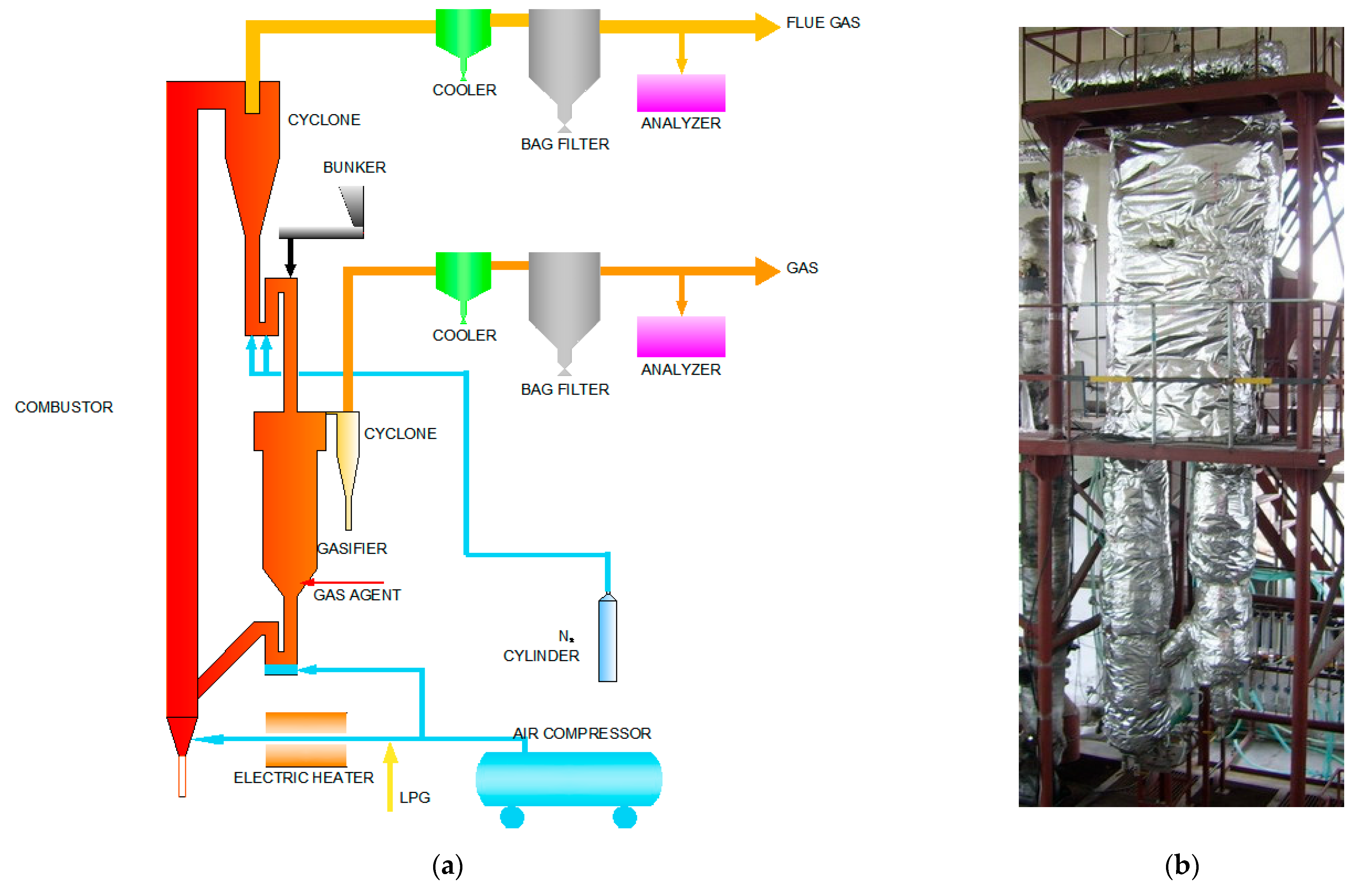
Figure 1. (a) Schematic layout of dual-fluidized bed system; (b) the physical image [13].
Energies 17 02381 g001
Figure 2. The diagram of reaction zone of dual-fluidized bed system [13].
Energies 17 02381 g002
Figure 3. The simulated flow diagram by Aspen Plus.
Energies 17 02381 g003
Figure 4. The comparison of experimental and simulated gas composition curves with temperature.
Energies 17 02381 g004
Figure 5. The comparison of experimental and simulated gas composition curves with ER.
Energies 17 02381 g005
Figure 6. The temperature trend with biomass feeding.
Energies 17 02381 g006
Figure 7. The gas fraction trend with biomass feeding.
Energies 17 02381 g007
Figure 8. The QV and GV trends with biomass feeding.
Energies 17 02381 g008
Figure 9. The ηc and η trends with biomass feeding.
Energies 17 02381 g009
Figure 10. The temperature trend with circulating bed material quantity.
Energies 17 02381 g010
Figure 11. The gas fraction trend with circulating bed material quantity.
Energies 17 02381 g011
Figure 12. The QV and GV trends with circulating bed material quantity.
Energies 17 02381 g012
Figure 13. The ηc and η trends with circulating bed material quantity.
Energies 17 02381 g013
Figure 14. The temperature trend with ER.
Energies 17 02381 g014
Figure 15. The gas fraction trend with ER.
Energies 17 02381 g015
Figure 16. The QV and GV trends with ER.
Energies 17 02381 g016
Figure 17. The ηc and η trends with ER.
Energies 17 02381 g017
Figure 18. The temperature trend with S/B.
Energies 17 02381 g018
Figure 19. The gas fraction trend with S/B.
Energies 17 02381 g019
Figure 20. The QV and GV trends with S/B.
Energies 17 02381 g020
Figure 21. The ηc and η trends with S/B.
Energies 17 02381 g021
Figure 22. The change trend of ϕCH4.
Energies 17 02381 g022
Figure 23. The change trend of ϕCO2.
Energies 17 02381 g023
Figure 24. The change trend of ϕCO.
Energies 17 02381 g024
Figure 25. The change trend of ϕH2.
Energies 17 02381 g025
Figure 26. The change trends of QV and GV.
Energies 17 02381 g026
Figure 27. The temperature and CaCO3 trends with circulating bed material quantity.
Energies 17 02381 g027
Figure 28. The ηc and η trends with (and without) CaO.
Energies 17 02381 g028
Table 1. Ultimate and proximate analyses of the CHR (air-dried basis) [12].
Ultimate Analysis
(wt%)
Proximate Analysis
(wt%)
LHV
(kJ/kg)
CHNSOMAVFc15,300
42.316.013.230.2532.615.4510.1467.3417.07
Table 2. The selected Aspen Plus models for united operations in the simulations and main functions.
Module NameCorresponding ModuleMain Functions
Pyrolysis ModuleRyieldConverting unconventional components in biomass into conventional simple components and semi-coke.
Transformation Reaction ModuleRgibbsThe components such as C, H2, O2, N2, S, and CaO from the pyrolysis module and CO, CO2, H2O, H2, and N2 from the semi-coke gasification module are converted, based on the principle of minimizing Gibbs free energy, into compounds including CO, CO2, CH4, H2, N2, H2O, H2S, and CaCO3. Tar components are not considered.
Semi-coke Gasification ModuleRgibbsThe semi-coke from the pyrolysis module is reacted with air or steam, etc., according to the principle of minimizing Gibbs free energy, to produce CO, H2, etc. The bed material also includes SiO2.
Combustion ModuleRgibbsThe semi-coke from the semi-coke gasification module and certain components such as C, H2, O2, N2, and S from the pyrolysis module are mixed with air and reacted according to the principle of minimizing Gibbs free energy, releasing heat to heat the circulating bed material. Calcium carbonate (CaCO3) from Sep5 also decomposes into CaO and CO2 under high-temperature conditions.
Separation Module Sep1Sep2The simple components such as C, H2, O2, N2, S, etc. from the pyrolysis module and the semi-coke are separated, and a portion of these components, including C, H2, O2, N2, S, etc., is transported to the combustion module for reaction according to the Fortran subroutine.
Separation Module Sep2Sep2The separation of the gaseous and solid products from the semi-coke gasification module is achieved.
Separation Module Sep3Sep2The separation of the gaseous and solid products from the combustion module is achieved.
Separation Module Sep4SsplitThe real-time slag disposal function is implemented. According to Fortran subroutine, the circulating bed material from separation module 3 is separated, with a portion being discharged as slag and another portion being recycled back to the pyrolysis module to provide energy for the thermal decomposition of biomass feedstock.
Separation Module Sep5Sep2The gas is separated from CaO and CaCO3. CaO and CaCO3 are transported to the combustion module for reaction.
Table 3. Main influencing factors of gasification process.
ParameterNumericalUnitVariable Adjustment Range for Sensitivity Analysis
Biomass Feed Rate8kg/h4~20
Circulating Bed Material Flow Rate1800kg/h300~2900
ER0.1/0.02~0.32
S/B0/0~0.28
Table 4. Process streams’ composition and flow rates.
MATERIALCALCIUMC-CYCGAS-PROD
Material Mass Flowkg/h8.00---
H2Omol/h---6.43
COmol/h---20.52
CO2mol/h---4.72
N2mol/h---3.21
H2mol/h---75.02
CH4mol/h---6.24
Total Mole Flowmol/h-4223.0521.42116.14
Total Mass Flowkg/h8.00237.420.26-
CaOmol/h-4201.95--
CaCO3mol/h-21.11--
Cmol/h--21.42-
Disclaimer/Publisher’s Note: The statements, opinions and data contained in all publications are solely those of the individual author(s) and contributor(s) and not of MDPI and/or the editor(s). MDPI and/or the editor(s) disclaim responsibility for any injury to people or property resulting from any ideas, methods, instructions or products referred to in the content.