Article

Simulation Study on Combustion Performance of Ammonia-Hydrogen Fuel Engines

1
State Key Laboratory of Engines, Tianjin University, 135 Yaguan Road, Tianjin 300350, China
2
GAC Research and Development Center, 668 Jinshan Road East, Guangzhou 511434, China
*
Author to whom correspondence should be addressed.
Energies 2024, 17(10), 2337; https://doi.org/10.3390/en17102337
Submission received: 11 April 2024 / Revised: 1 May 2024 / Accepted: 10 May 2024 / Published: 13 May 2024
(This article belongs to the Topic Advanced Engines Technologies)

Abstract

:
Ammonia is a very promising alternative fuel for internal combustion engines, but there are some disadvantages, such as difficulty in ignition and slow combustion rate when ammonia is used alone. Aiming to address the problem of ammonia combustion difficulty, measures are proposed to improve ammonia combustion by blending hydrogen. A one-dimensional turbocharged ammonia-hydrogen engine simulation model was established, and the combustion model was corrected and verified. Using the verified one-dimensional model, the effects of different ratios of hydrogen to ammonia, different rotational speeds and loads on the combustion performance are investigated. The results show that the ignition delay and combustion duration is shortened with the increase of the hydrogen blending ratio. The appropriate amount of hydrogen blending can improve the brake’s thermal efficiency. With the increase in engine speed, increasing the proportion of hydrogen blending is necessary to ensure reliable ignition. In conclusion, the ammonia-hydrogen fuel engine has good combustion performance, but it is necessary to choose the appropriate hydrogen blending ratio according to the engine’s operating conditions and requirements.

1. Introduction

Currently, about 85% of the world’s energy comes from non-renewable sources such as oil, coal, and natural gas [1], which inevitably produce carbon emissions when used. Recent data from the World Resources Institute indicate that transport-related carbon emissions account for a significant portion of total energy carbon emissions, with road transport alone accounting for more than 70 percent [2]. As an important power source in modern industry and transportation, the internal combustion engine is still commonly used as fossil fuels such as gasoline and diesel [3,4,5,6]. Therefore, in the face of climate change and the growing threat to the environment posed by fossil fuel consumption, there is an urgent need to develop new technologies or find alternative fuels for internal combustion engines to alleviate environmental problems. Hydrogen and ammonia are two carbon-free fuels that have attracted much attention and have broad application prospects. Hydrogen gas possesses advantages such as low ignition energy, wide flammability limits, fast flame propagation velocity, and zero carbon emissions [7,8]. However, it faces challenges, including storage issues, safety concerns related to abnormal combustion, and incomplete infrastructure for hydrogen refueling stations [9,10,11]. In contrast, ammonia, as a product of nitrogen and hydrogen synthesis, can be liquefied and stored under standard conditions (liquefaction can be achieved at −33 °C under atmospheric pressure or at atmospheric temperature with 0.8~1.0 MPa pressure) [12]. Therefore, ammonia serves as an excellent carrier for hydrogen, offering advantages such as high energy density, ease of liquefaction and transportation. Moreover, existing refueling stations can meet the demand for liquid ammonia refueling [13,14]. However, ammonia gas exhibits lower chemical reactivity, difficulty in ignition, and slow combustion rate, so it is necessary to blend high-reactivity fuels to display their superior performance [15,16]. Research and application of ammonia-hydrogen blending fuel engines offer new possibilities for mitigating climate change, achieving energy security, and promoting sustainable development in the transportation sector.
Pure ammonia-fueled internal combustion engines face many challenges due to the unfavorable combustion characteristics of ammonia, such as high auto-ignition temperature, small flammability limit, low laminar flame velocity and high latent heat of vaporization [17,18,19]. Therefore, researchers have shifted their focus to the application of ammonia blending with other reactive fuels. Blending ammonia with fuels such as gasoline, diesel, ethanol, methanol, Dimethyl Ether (DME), Diethyl Ether (DEE), and kerosene has been widely attempted. For example, Grannell et al. [20] used more than 50% ammonia blending gasoline to achieve stable operation in a spark ignition engine. As the engine load decreases, the maximum percentage of ammonia fuel allowed in the blending fuel decreases to ensure the engine operates. Gross and Kong [21] conducted a series of tests in compression-ignition engines using different blending rates of ammonia and DME, and the results showed that with 20% NH3–80% DME and 40% NH3–60% DME, the ignition delay time was long due to the high spontaneous combustion temperature of ammonia and slow flame speed, which limits engine load increase. When the injection pressure of DME was increased by 30 bar, blends with higher ammonia content could be used, resulting in improved combustion and emission performance. Niki et al. [16] added ammonia to a diesel engine and found that the maximum in-cylinder pressure decreased, and the ignition timing was delayed with the rise of the NH3 ratio in the blending fuel. In the exhaust gas, NH3, water and N2O increased with the NH3 ratio increasing, CO2 decreased, and NOX emissions were approximately invariable.
In addition to blending with hydrocarbon fuels, ammonia blending with hydrogen gas has great application potential. The use of hydrogen gas as a combustion promoter can completely eliminate carbon emissions from the engine, as hydrogen can be produced through ammonia decomposition, avoiding the need for bulky hydrogen storage containers [22,23,24,25,26]. Comotti et al. [27] successfully separated hydrogen gas from ammonia gas using a catalytic cracking reactor and demonstrated that adding hydrogen gas improved engine operation stability. Frigo et al. [28] validated that the engine required minor modifications to accommodate ammonia-hydrogen mixtures for combustion, such as adding electronically controlled injectors for hydrogen and ammonia injecting into the intake manifold. The proportion of ammonia and hydrogen in the mixed fuel varies mainly depending on the engine load. Due to the lower calorific value difference of the mixed gas with the gasoline and due to the lower flame speed of ammonia, the brake thermal efficiency (BTE) and power output of the blending fuel engine are lower than that of the gasoline engine. The engine produced 12 kW of effective power at 50% load and 4500 r/min, with maximum NOX emissions of 11.5 g/(kW·h). Pochet et al. [29] conducted experimental tests on pure ammonia and ammonia-hydrogen mixtures under different intake temperatures, pressures, equivalence ratios, and exhaust gas recirculation rates in a single-cylinder homogeneous compression ignition engine, analyzing the effects of various factors on engine performance and emissions characteristics. The research found that under limited conditions (maximum cylinder pressure ≤120 bar, maximum pressure rise rate ≤12 bar/°CA), using blended fuel of hydrogen with ammonia yielded a 50% increase in IMEP compared to using pure hydrogen fuel while maintaining similar thermal efficiency. However, nitrogen oxide emissions increased linearly with the proportion of ammonia in the mixed fuel, reaching up to 6000 ppm.
In conclusion, numerous studies on ammonia fuel demonstrate its performance advantages as an alternative fuel in internal combustion engines when blended with high-reactivity fuels. However, research on ammonia-hydrogen blending fuel primarily focuses on the feasibility of using ammonia-hydrogen mixtures as engine fuels, and the performance and emissions of the engines under specific conditions [30,31,32,33]. This paper builds on the previously demonstrated potential of the ammonia-hydrogen fuel by establishing a one-dimensional simulation model. Aiming at the problem that the GT-Power model is not suitable for ammonia-hydrogen fuel combustion, CHEMKIN 2021 software is used to calculate the laminar flame velocity of ammonia-hydrogen fuel, re-fit the laminar flame velocity formula of ammonia-hydrogen combustion, and verify the combustion model with experimental data. The sensitivity analysis of ignition delay of ammonia-hydrogen fuel is carried out to study the effects of hydrogen blending ratio and ignition time on combustion and performance of the engine under different load and speed conditions.

2. Simulation Modeling and Model Verification

2.1. Simulation Modeling

In this paper, a one-dimensional model of a turbocharged ammonia-hydrogen engine is constructed based on a modified 1.5 L gasoline engine. The main parameters of the engine are listed in Table 1. The constructed model includes parts of the intake and exhaust system, fuel supply system, flow model, heat transfer model and combustion model. The Woschni heat transfer model, Chen–Flynn friction model and SI-turb combustion model were used in the one-dimensional simulation of the engine. The structure of the one-dimensional model is shown in Figure 1.

2.2. Laminar Flame Velocity Model Correction and Verification

In the combustion model of GT-power, the mixture combustion rate is determined by the laminar flame velocity and turbulent flame speed [34], and the calculation equations are given as follows.
d M e d t = ρ u A e ( S L + S T )
S L = S L 0 ( T u / T r e f ) α ( p / p r e f ) β D i
S L 0 = B m + B φ ( φ φ m ) 2
where Me is the mass of the unburned mixture, t is the time after spark plug ignition, ρu is the density of the unburned mixture, Ae is the surface area of the flame front at the boundary, SL is the laminar flame velocity, ST is the turbulent flame velocity, SL0 is the laminar flame velocity at the reference pressure and temperature, Tu is the temperature of unburned gas, Tref is the reference temperature, which is taken as 298 K in calculations, α is the temperature exponent, p is the pressure inside the cylinder, Pref is the reference pressure, which is taken as 101,325 Pa in the calculation, β is the pressure index, Bm is the maximum laminar flame velocity, Bφ is the reduced value of laminar flame velocity, φ is the equivalence ratio, φm is the equivalence ratio at the maximum laminar flame velocity, and Di is the dilution coefficient of exhaust gas.
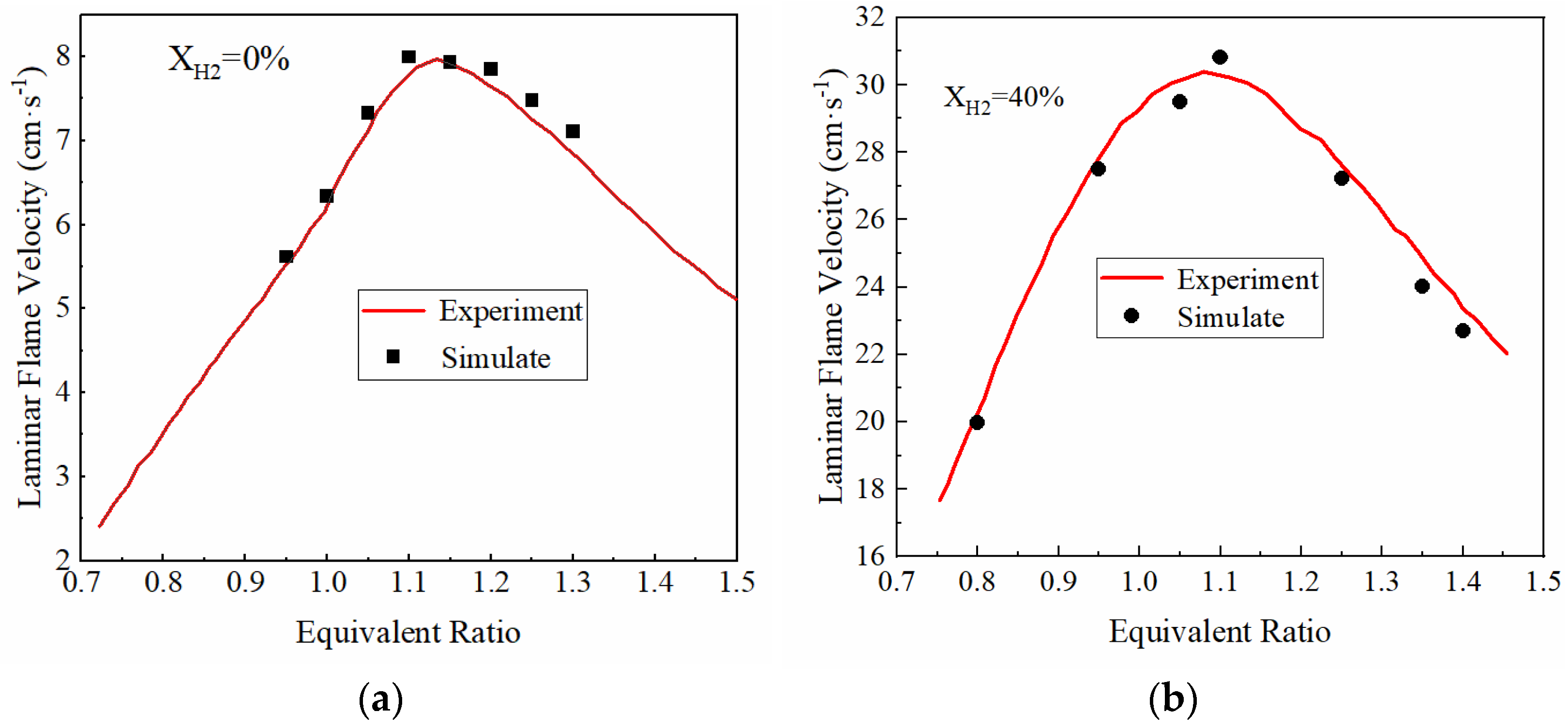
In the laminar flame velocity equations, Bm, Bφ, φm, α and β are unknown and need to be determined by fitting and correcting the laminar flame velocity obtained in the experiment. In order to obtain the parameters of the laminar flame velocity equation, it is necessary to obtain the laminar flame velocity of ammonia-hydrogen mixture fuel at different equivalent ratios and to fit the laminar flame velocity equation. Therefore, this paper first established a simulation model of ammonia-hydrogen fuel through CHEMKIN software. The combustion mechanism of the ammonia-hydrogen mixture proposed by Zhang X et al. [35] is adopted as the chemical reaction kinetics mechanism of CHEMKIN. Experimental data of Mei et al. [36] and Lhuillier et al. [37] are then used to verify the CHEMKIN model. The experimental data included the laminar flame velocity of the fuel mixture with pure ammonia and 40% hydrogen at standard atmospheric conditions (298 K, 101 KPa). As shown in Figure 2, the laminar flame velocity simulated using CHEMKIN software is in good agreement with the experimental data, and thus, the CHEMKIN model can be used to calculate the laminar flame velocity.
After verifying the accuracy of the model, the hydrogen blending ratio (energy proportion) of four different mixed fuels was selected, which are 0%, 12%, 23%. and 46%, respectively. The energy ratio calculation formula is shown in Equation (4), and the hydrogen mass fraction and volume fraction corresponding to the four hydrogen blended energy ratios are shown in Table 2.
E H 2 = Q H 2 Q H 2 + Q N H 3 100 %
where EH2 is the energy ratio of hydrogen, QH2 is the total energy generated by the complete combustion of hydrogen in a single cycle, and QNH3 is the total energy generated by the complete combustion of ammonia in a single cycle.
CHEMKIN software is used to calculate the laminar flame velocity using the Flame Speed module of the software in the standard state, and the hydrogen blending fuels with different equivalence ratios are selected for the simulation calculations. After the calculation, two different laminar flame velocity equations are used for fitting; one is the standard state laminar flame velocity Equation (3) (polynomial equation) used in GT-power’s SI-turb combustion model, and the other is a fractional equation as shown in Equation (5) [38].
S L 0 = a φ 2 + b φ φ 2 + c φ + d
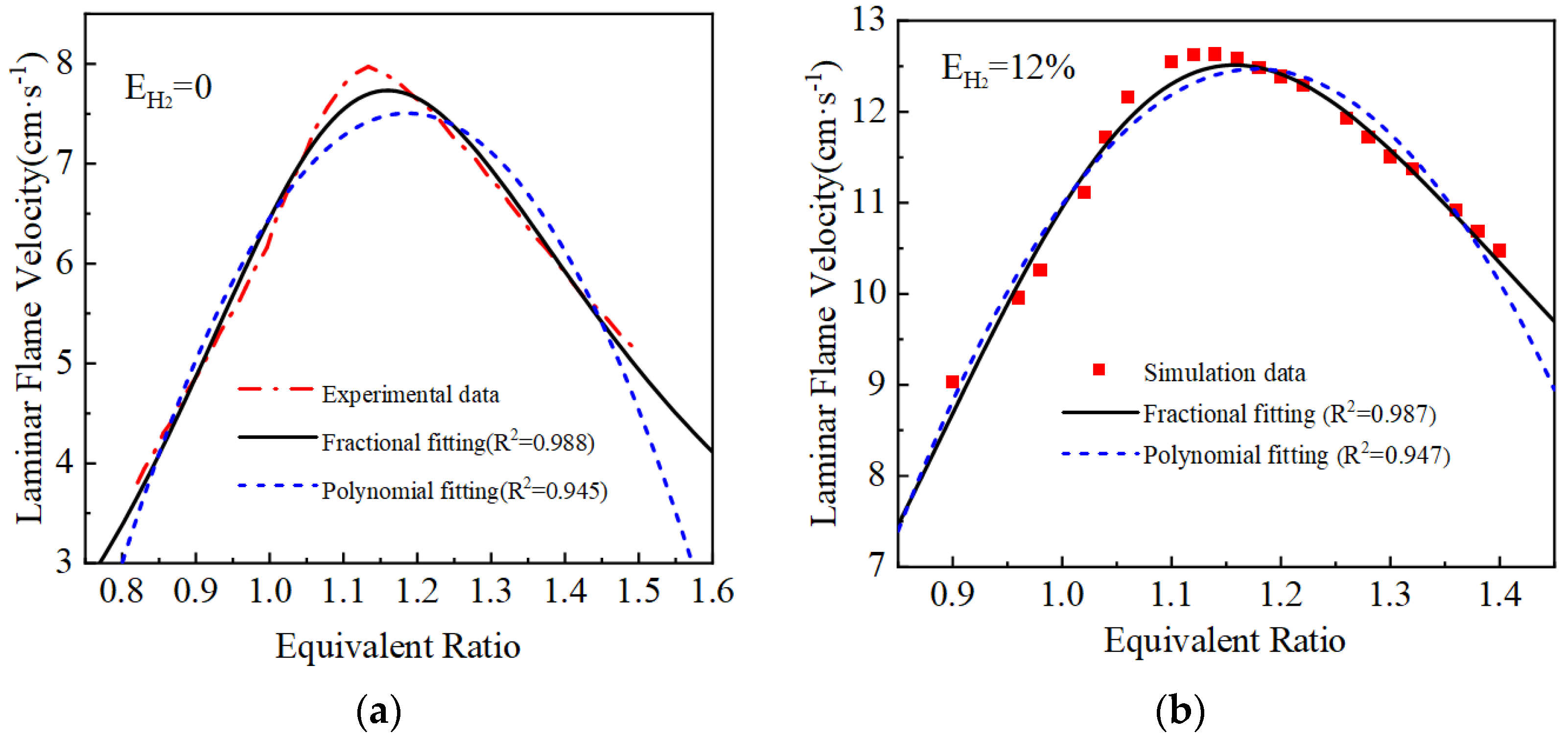
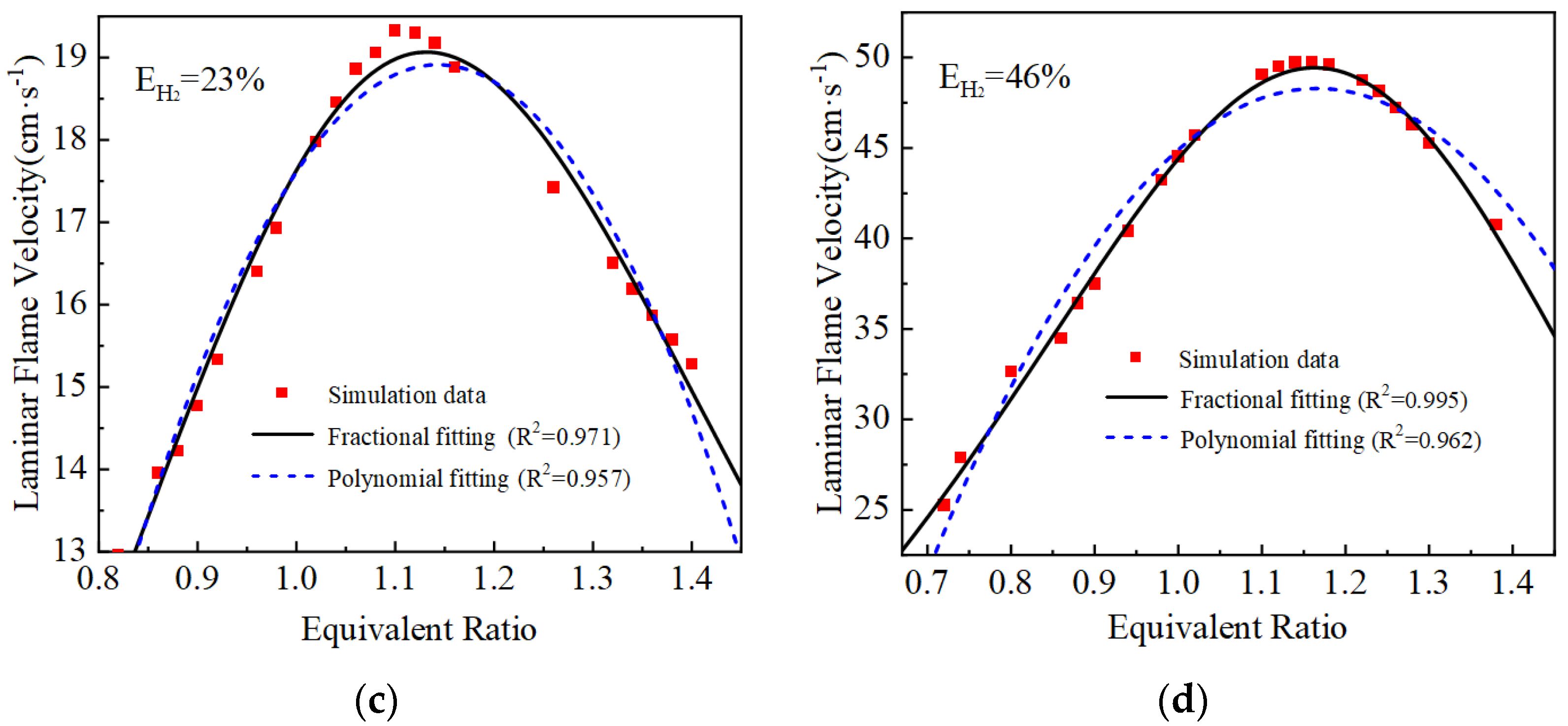
The laminar flame velocity calculated and the two laminar flame velocity equations fitted are shown in Figure 3. The goodness of fit R2 of the polynomial fit is around 0.95, while the fractional equation fit is better compared with the polynomial fit equation, and the goodness of fit R2 of the curves are all greater than 0.97. Therefore, the fractional fitting equations are used, and the fitted fractional equations are shown in Table 3.
For the calculation of the temperature factor α and pressure factor β in Equation (2), the conclusions presented by Goldmann et al. [38] by utilizing the open-source software Cantera were used to simulate the laminar flame velocity, and the calculated temperature factor and pressure factor expressions for the four hydrogen blending ratios are given as follows.
α 1 = 4.5147 φ 5 + 48.2623 φ 4 107.2316 φ 3 + 106.5883 φ 2 48.5793 φ + 8.3178 φ 5
β 1 = 1.8762 φ 5 + 8.0322 φ 4 14.8417 φ 3 + 13.2677 φ 2 5.7168 φ + 0.9429 φ 5
α 2 = 6.321 φ 3 9.481 φ 2 + 7.493 φ 1.639 φ 3
β 2 = 0.5019 φ 4 + 1.493 φ 3 2.358 φ 2 + 1.51 φ 0.3421 φ 4
α 3 = 5.635 φ 3 8.359 φ 2 + 6.901 φ 1.602 φ 3
β 3 = 0.4489 φ 4 + 1.223 φ 3 1.947 φ 2 + 1.165 φ 0.2442 φ 4
α 4 = 4.998 φ 3 7.364 φ 2 + 6.441 φ 1.568 φ 3
β 4 = 0.2624 φ 4 + 0.2205 φ 3 0.6964 φ 2 + 0.4875 φ 0.1131 φ 4

2.3. GT-Power Model Validation

After correcting the laminar flame velocity model, the GT-power model is experimentally validated for different blending ratios based on the experimental data of cylinder pressure and heat release rate from Pyrc et al. [39]. Figure 4 demonstrates the cylinder pressure and heat release rate of the simulation results compared with the experimental data. It can be observed that the simulation results match well with the cylinder pressure of the experimental data at different hydrogen blending ratios. Although there are some errors in the heat release rate at the beginning and end stages of combustion, these errors are acceptable for the engineering application. Therefore, it can be concluded that the model can be used to simulate the combustion process of an ammonia-hydrogen internal combustion engine.

3. Combustion Characterization of Ammonia-Hydrogen Engine

In Section 2, CHEMKIN software is used to calculate the laminar flame velocity of ammonia-hydrogen mixture fuel, and the laminar flame velocity equation is re-fitted and applied to the combustion model of GT-power v2016 software. In this chapter, based on CHEMKIN software, the influence of different hydrogen blending ratios on the ignition delay is studied, and the sensitivity analysis is carried out. The influence of each elementary reaction on the ignition delay is revealed from the chemical reaction kinetics mechanism. Then, based on GT-power software, the effects of different blending ratios, different speeds, and different brake mean effective pressures (BMEP) on the performance of the ammonia-hydrogen engine are investigated. The settings of each working condition are shown in Table 4.

3.1. Sensitivity Analysis of Ignition Delay

The length of the ignition delay directly affects the combustion efficiency, engine performance, emission species composition and quantity. Therefore, a thorough understanding of the factors affecting ignition delay is very important for combustion system design and optimization. In this section, CHEMKIN software is used to analyze the effects of different hydrogen blending ratios (0%, 12%, 23%, 46%) on the ignition delay of ammonia-hydrogen mixtures under the equivalent combustion conditions and the law of the influence of each elementary reaction on the ignition delay is revealed. Through sensitivity analysis and calculation, the ten reactions that have the strongest influence on the combustion delay period with different hydrogen blending ratios are obtained. The reaction numbers and equations are shown in Table 5. Reactions with the same chemical formula (such as R2 and R3) are repeated because some reactions may occur in multiple different pathways or have multiple important intermediates in the chemical kinetics simulation. In this case, to ensure that all relevant pathways are taken into account, a repeat reaction is set up to meet the simulation requirements.
Sensitivity analysis helps to identify which chemical reaction steps play a key role in the combustion process at different hydrogen blending ratios. The sensitivity analysis results are presented in the form of sensitivity coefficients, which quantitatively represent the sensitivity of the target output to changes in the constant reaction rate. A positive sensitivity coefficient means that an increase in the rate constant will reduce the ignition delay, while a negative sensitivity coefficient means that an increase in the rate constant will increase the ignition delay. The simulation results of sensitivity analysis are shown in Figure 5.
As can be seen from Figure 5, the increase in the hydrogen blending ratio leads to a larger sensitivity coefficient for reactions related to hydroxyl radical (OH) (e.g., R3, R4, R162). The results show that the effect of hydroxyl radical on the ignition delay is enhanced at high hydrogen blending ratio, which may be due to the high reactivity of hydrogen, which can accelerate the formation and consumption of free radicals, thus affecting the overall reaction rate and ignition characteristics of combustion.
During the combustion of ammonia-hydrogen fuel, the generation and consumption of free radicals have a great influence on the combustion delay period. In the case of a high blending ratio of hydrogen, the formation of OH radicals will be promoted due to the fast reaction rate of hydrogen. The reaction of OH radicals with the fuel produces more free radicals and pushes the reaction towards the formation of the final combustion product. The HO2 free radical is easily decomposed in the high-temperature combustion environment, releasing OH free radicals, which also helps to accelerate the combustion process.
In addition, in the absence of hydrogen mixing, reactions involving nitrogen oxygen radical (NO) and nitrogen hydrogen radical (NH, NH2, NH3) (such as R64, R69, R219) show high sensitivity, and these reactions have significant negative effects on the ignition delay, but with the increase of hydrogen blending ratio, the sensitivity of these reactions decreases. This suggests that the presence of hydrogen may alter the path of free radical consumption and promote the ignition process. The ignition of pure ammonia fuel mainly depends on its own reaction characteristics. Reactions involving the formation of hydroxyl groups by nitrogen and hydrogen radicals (e.g., R63 and R68) significantly positively affect the ignition delay when the hydrogen blending ratio is 0%. This may be due to the formation of OH radicals in these reactions, which speeds up the rate of the combustion reaction. The sensitivity of these reactions decreases as the hydrogen blending ratio increases, possibly because the presence of hydrogen changes the dominant reaction path of combustion, thereby reducing the impact of these reactions on the ignition delay.
In summary, the hydrogen blending ratio has a significant effect on the generation and consumption of free radicals in the combustion process and then affects the ignition delay. Free radicals such as OH and HO2 are the key intermediates to control ignition delay, and their reaction sensitivity is directly related to the ignition characteristics of fuels. With the increase of the hydrogen blending ratio, the sensitivity of reactions related to free radicals changes greatly. The addition of hydrogen can inhibit the strong negative sensitive elementary reactions (such as R64, R69, R219) in the combustion process of pure ammonia and reduce the ignition delay, which fully shows the role of hydrogen in shortening the combustion delay period, improving the combustion efficiency of ammonia and optimizing the combustion process.

3.2. Effect of Hydrogen Blending Ratio on the Combustion Characteristics

The hydrogen blending ratio directly affects the composition of the combustible mixture in the cylinder, which directly influences the physical and chemical properties of the combustible mixture, so it is necessary to study the influence of the hydrogen blending ratio on the combustion characteristics.
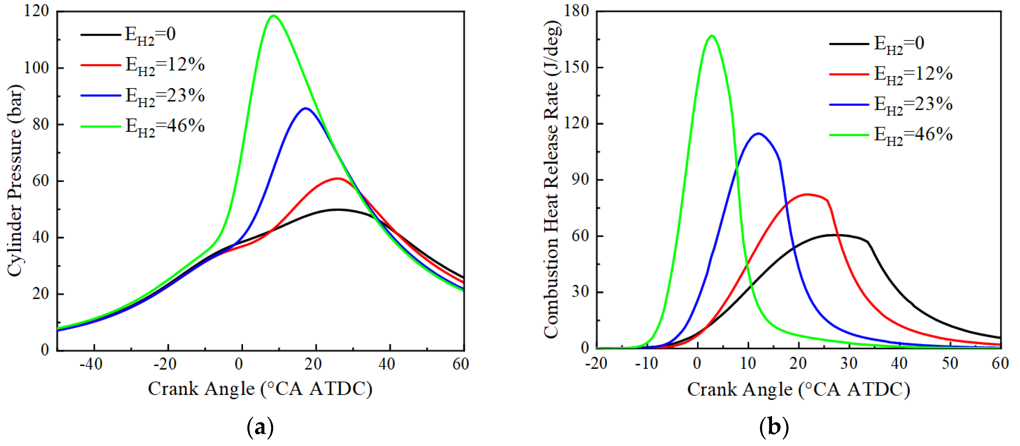
The variation of cylinder pressure and heat release rate with crankshaft angle for pure ammonia fuel with an ignition advance angle of 30 °CA BTDC and hydrogen blending fuel with an ignition advance angle of 20 °CA BTDC at BMEP = 15 bar and 1500 r/min is given in Figure 6. From Figure 6, it can be seen that the peak cylinder pressure tends to increase monotonically with the increase of hydrogen blending ratio, and the crankshaft angle corresponding to the maximum pressure is advanced. The peak cylinder pressures and their corresponding crankshaft angles at 0%, 12%, 23%, and 46% hydrogen blending ratios are respectively 49.9 bar and 25.4 °CA ATDC, 60.9 bar and 25.4 °CA ATDC, 85.8 bar and 17.1 °CA ATDC, 118.6 bar and 8.4 °CA ATDC, and the corresponding peak heat release rates and their corresponding crankshaft angles are respectively 60.5 J/deg and 27.1 °CA ATDC, 82.2 J/ deg and 22.1 °CA ATDC, 114.8 J/deg and 12.0 °CA ATDC, 167.1 J/deg and 2.6 °CA ATDC. Due to the low ammonia activity, a large ignition advance angle is required for successful ignition. After hydrogen blending, the flame propagation speed is accelerated, accompanied by an increase in the constant volume degree of combustion and advancement in the crankshaft angle corresponding to the peak engine cylinder pressure and heat release rate. This is because hydrogen has the advantages of low ignition energy and fast combustion speed. At the same time, the increase in the engine cylinder temperature and the increase in combustion constant volume degree after hydrogen blending lead to an increase in the peak cylinder pressure of the engine. In the case of pure ammonia fuel, the peak of the heat release rate is lower, and the moment of reaching the peak is delayed. This indicates that ammonia is characterized by a slow combustion rate and long ignition delay. As the hydrogen blending ratio increases, the peak of the heat release rate increases significantly and reaches the peak earlier. This is consistent with the results of the cylinder pressure analysis and further confirms the effect of hydrogen addition on improving combustion.
The combustion stability of the spark ignition engine is mainly affected by the state of the flame at the early stage, so it is necessary to analyze the ignition delay, combustion duration and other combustion characteristics of the engine under the different hydrogen blending ratios.
Figure 7a shows the variation of the ignition delay for different hydrogen blending ratios at BMEP = 15 bar and 1500 r/min. Due to the lower ignition energy of hydrogen, the ignition delay decreases with the increase of hydrogen blending ratio at the same ignition advance angle, and the average ignition delays are, respectively, 30.3, 15.5, 11.7, and 6.8 °CA for 0%, 12%, 23%, and 46% hydrogen blending ratios. In addition, the effect of ignition timing on the ignition delay becomes smaller with increased hydrogen blending ratio. Figure 7b demonstrates the variation of combustion duration with ignition advance angle for engines with different hydrogen blending ratios. It can be seen that the combustion duration is shortened with the increase of hydrogen blending ratio, and the average combustion durations at 0%, 12%, 23%, and 46% hydrogen blending ratios are 23.3, 19.2, 15.3, and 12.4 °CA, respectively. This is because the fast flame propagation speed of hydrogen leads to the shortening of combustion duration, and the higher flame temperature of the hydrogen accelerates the combustion of the mixture.

3.3. Effect of Rotational Speed on Combustion Characteristics

During engine operation, rotational speed variation affects the in-cylinder gas flow and pumping losses etc. In order to study the effect of rotational speed on the combustion process, the BTE and operational stability were calculated and analyzed at 1500, 2500 and 3500 r/min while keeping the brake mean effective pressure (BMEP) constant at 15 bar.
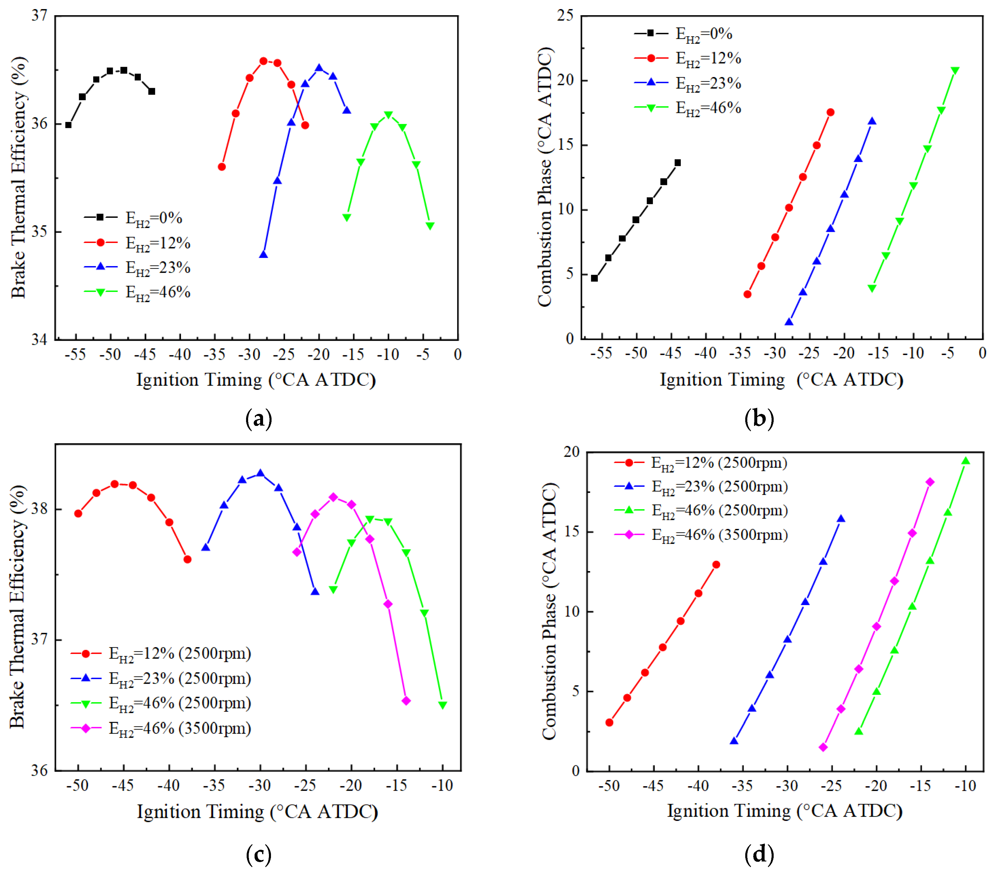
Figure 8 shows the variation of BTE and combustion phase of the engine with ignition timing for different blending ratios at 1500, 2500 and 3500 r/min. At 1500 r/min, the optimal BTE corresponding to 0%, 12%, 23%, and 46% hydrogen blending ratios are 36.5%, 36.6%, 36.5%, and 36.1%, respectively, and their corresponding ignition timing and combustion phases are −48 and 10.6 °CA ATDC, −28 and 10.2 °CA ATDC, −20 and 11.2 °CA ATDC, and −10 and 11.9 °CA ATDC, respectively. At 2500 r/min, the ignition of the pure ammonia fuel fails, and the best BTE corresponding to the three different blending ratios of 12%, 23%, and 46% are respectively 38.2%, 38.3%, and 37.9%, and their corresponding ignition timings and combustion phases are −46 and 6.2 °CA ATDC, −30 and 8.2 °CA ATDC, and −18 and 7.5 °CA ATDC, respectively. At 3500 r/min, only the fuel with a hydrogen blending ratio of 46% could ignite successfully, and the optimal BTE is 38.1%, corresponding to the ignition timing and the combustion phase of −22 and 6.4 °CA ATDC. It can be seen that by adjusting the ignition timing and the combustion phase angle, the brake thermal efficiency and combustion stability of the engine can be optimized for different rotational speeds and hydrogen blending ratios. However, the failure to ignite at certain speeds and hydrogen blending ratios suggests that fuel composition plays a key role in achieving optimal combustion performance.
The above analysis reveals that when the rotational speed reaches 3500 r/min, only the 46% hydrogen blending ratio can be ignited successfully. In order to explore the performance at speeds above 3500 r/min under a 46% hydrogen blending ratio, the performances of 4000 to 5500 r/min are simulated. Figure 9 shows the BTE and combustion phase changes of the 46% hydrogen blended fuel at 4000, 4500, 5000, and 5500 r/min. From the graph of BTE, the BTE decreases with the increase in rotational speed. At 4000 r/min, the BTE is 37.8%, but still less than the optimum brake thermal efficiency at 3500 r/min. From the graph of the combustion phase, it can be seen that in the range of 4000 to 5500 r/min, the combustion phase lags with the increase of the rotational speed. This is because the higher the rotational speed, the greater the angle of rotation of the crankshaft at the same time, which will cause the combustion to continue at a greater angle. Meanwhile, in the simulation, it was found that the engine could not be stably ignited when the speed continued to be increased to 6000 r/min, and therefore, no further numerical simulations were conducted.

3.4. Effect of Load on Combustion Characteristics

In the actual working process, the engine load is constantly changing. Therefore, it is essential to study the engine’s thermal efficiency and combustion stability under different loads. In this section, the excess air coefficient is set to be 1, the rotational speeds are 1500 r/min, 2500 r/min, and 3500 r/min, and three different loads are selected, which correspond to the BMEP of 10 bar, 15 bar, and 20 bar, respectively. Since the previous section has analyzed the working conditions with a BMEP of 15 bar, this section only focuses on the working conditions with a BMEP of 10 bar and 20 bar to investigate the performance of the engine under these two loads.
Figure 10 and Figure 11 show the variation of BTE with ignition timing for using different blending ratios of fuels under different loads. As can be seen from Figure 10, when BMEP = 10 bar, the optimal thermal efficiencies corresponding to 0%, 12%, 23%, and 46% hydrogen blending ratios are 35.6%, 35.9%, 36.0%, and 35.8%, respectively, at 1500 r/min. The pure ammonia fuel fails to ignite at 2500 r/min, and the optimal effective thermal efficiencies corresponding to the other three different blending ratios of 12%, 23% and 46% are 36.8%, 37.1% and 37.1%, respectively. The optimal thermal efficiency is 36.9% for a 46% hydrogen blending ratio at 3500 r/min. When BMEP = 20 bar, the optimal thermal efficiencies are respectively 36.6%, 36.6%, 36.5%, and 36.1% for 0%, 12%, 23%, and 46% hydrogen blending ratio at 1500 r/min. When the rotational speed is 2500 r/min, the optimal thermal efficiency corresponding to 23% and 46% hydrogen blending ratio is 38.5% and 38.1%, respectively. When the rotational speed is 3500 r/min, the optimal thermal efficiency corresponding to a 46% hydrogen blending ratio is 38.3%. From the research on the load effect on BTE, the optimal BTE increases with the increase of the BMEP.
When the load is low (BMEP = 10 bar), the ignition timing corresponding to the optimal BTE is earlier, especially more advanced for pure ammonia fuel, due to the lower amount of fuel per cycle and the lower flame speed during engine operation. For example, the ignition timings corresponding to the optimal BTE at 1500 rpm for pure ammonia fuel at BMEP = 10, 15 bar are −90 and −48 °CA ATDC, respectively, with the difference reaching 42. However, when the hydrogen blending ratios are 12%, 23%, and 46% at two different loads, the ignition timings corresponding to the optimal BTE are 14°, 6°, and 4°, respectively, which also indicates that a small amount of hydrogen blending can make the optimal ignition timing differences significantly reduce under different loads.
At 1500 r/min, 12% and 23% hydrogen blending fuel present higher thermal efficiency than 0% and 46% hydrogen blending fuel when the BMEP is 10 bar and 20 bar. At 2500 r/min, 23% hydrogen blending fuel shows high BTE. When the rotation speed is equal to 1500 r/min for 46% hydrogen blending fuel, BTE is lower than that of the other two hydrogen blending fuels (12%, 23%) due to high combustion speed, which results in more heat losses.

4. Conclusions

In this paper, the effects of hydrogen blending ratio on engine combustion and performance under different operating conditions are simulated and investigated using a one-dimensional simulation model of an ammonia-hydrogen engine, and the following main conclusions are drawn:
(1)
With the increase of hydrogen blending ratio, the sensitivity of hydroxyl-related elementary reactions (e.g., R3: O + H2 = OH + H, R4: OH + H2 = H + H2O) increases. In the combustion of pure ammonia fuel, the reaction involving nitrogen oxygen and nitrogen hydrogen free radicals has a significant negative effect on the combustion delay period. The addition of hydrogen can inhibit the strong negative sensitive elementary reactions (R64: NH2 + HO2 = NH3 + O2, R69: NH2 + NO = N2 + H2O) in the ammonia combustion process, and can significantly shorten the ignition delay. Under the same ignition timing, with the increase of hydrogen blending ratio, the peak value of cylinder pressure and heat release rate increases, as does the corresponding peak value of the crankshaft. Angle advances and the ignition delay period and combustion duration become shorter.
(2)
Ammonia fuel, due to its low reactivity, requires a large ignition advance for successful ignition at 1500 rpm and does not ignite reliably at medium to high engine speeds. The fuel with 12% hydrogen blending has a high BTE of up to 36.6% at low speeds. As the engine speed increases, the ignition difficulty of the pure ammonia and low hydrogen blending ratio increases, and it is necessary to increase the hydrogen blending ratio to ensure reliable ignition.
(3)
The BTE of the blended fuel with a 23% hydrogen blending ratio at 2500 r/min has the highest BTE at BMEP = 10, 15, and 20 bar, with optimum thermal efficiencies of 37.1%, 38.5% and 38.3%, respectively. When the hydrogen blending ratio reaches 46%, BTE presents a small reduction. The possible reason is the high ratio of hydrogen blending produces large heat transfer losses due to rapid combustion. Under the speed of 3500 rpm, normal ignition can be ensured only when the hydrogen blending ratio reaches 46%. With the increase of the engine speed, it is necessary to appropriately increase the hydrogen blending ratio in order to obtain a higher BTE.

Author Contributions

Conceptualization, D.Z.; Data curation, D.Z., Y.L. and Z.F.; Formal analysis, D.Z., W.G. and Z.F.; Investigation, D.Z. and W.G.; Methodology, D.Z. and W.G.; Project administration, W.G. and Y.L.; Resources, D.Z., X.H. and Y.Z.; Software, Y.L.; Supervision, W.G. and Y.L.; Validation, D.Z. and W.G.; Visualization, D.Z.; Writing—original draft, D.Z.; Writing—review and editing, D.Z., W.G. and Z.F. All authors have read and agreed to the published version of the manuscript.

Funding

This research received no external funding.

Data Availability Statement

The original contributions presented in the study are included in the article, further inquiries can be directed to the corresponding authors.

Conflicts of Interest

The authors declare no conflicts of interest.

Nomenclature

ATDCAfter Top Dead Center
BMEPBrake Mean Effective Pressure
BTDCBefore Top Dead Center
BTEBrake Thermal Efficiency
CACrank Angle

References

  1. El-Adawy, M.; Nemitallah, M.A.; Abdelhafez, A. Towards sustainable hydrogen and ammonia internal combustion engines: Challenges and opportunities. Fuel 2024, 364, 131090. [Google Scholar] [CrossRef]
  2. Ritchie, H.; Roser, M.; Rosado, P. Fossil Fuels. Our World in Data. 2020. Available online: https://ourworldindata.org/fossil-fuels (accessed on 4 August 2022).
  3. Santos, N.D.S.A.; Roso, V.R.; Malaquias, A.C.T.; Baeta, J.G.C. Internal combustion engines and biofuels: Examining why this robust combination should not be ignored for future sustainable transportation. Renew. Sust. Energy Rev. 2021, 148, 111292. [Google Scholar]
  4. Lešnik, L.; Kegl, B.; Torres-Jiménez, E.; Cruz-Peragón, F. Why we should invest further in the development of internal combustion engines for road applications. Oil Gas. Sci. Technol.—Rev. d’IFP Energies Nouv. 2020, 75, 56. [Google Scholar] [CrossRef]
  5. Kalghatgi, G. Is it really the end of internal combustion engines and petroleum in transport? Appl. Energy 2018, 225, 965–974. [Google Scholar] [CrossRef]
  6. Verma, S.; Dwivedi, G.; Verma, P. Life cycle assessment of electric vehicles in comparison to combustion engine vehicles: A review. Mater. Today Proc. 2022, 49, 217–222. [Google Scholar] [CrossRef]
  7. Yan, F.; Xu, L.; Wang, Y. Application of hydrogen enriched natural gas in spark ignition IC engines: From fundamental fuel properties to engine performances and emissions. Renew. Sust. Energy Rev. 2018, 82, 457–1488. [Google Scholar] [CrossRef]
  8. Onorati, A.; Payri, R.; Vaglieco, B.M.; Agarwal, A.K.; Bae, C.; Bruneaux, G.; Canakci, M.; Gavaises, M.; Günthner, M.; Hasse, C.; et al. The role of hydrogen for future internal combustion engines. Int. J. Engine Res. 2022, 23, 529–540. [Google Scholar] [CrossRef]
  9. Stępień, Z. A comprehensive overview of hydrogen-fueled internal combustion engines: Achievements and future challenges. Energies 2021, 14, 6504. [Google Scholar] [CrossRef]
  10. Sun, Z.; Hong, J.; Zhang, T.; Sun, B.; Yang, B.; Lu, L.; Li, L.; Wu, K. Hydrogen engine operation strategies: Recent progress, industrialization challenges, and perspectives. Int. J. Hydrogen Energy 2023, 48, 366–392. [Google Scholar] [CrossRef]
  11. Qureshi, F.; Yusuf, M.; Kamyab, H.; Zaidi, S.; Khalil, M.J.; Khan, M.A.; Alam, M.A.; Masood, F.; Bazli, L.; Chelliapan, S.; et al. Current trends in hydrogen production, storage and applications in India: A review. Sustain. Energy Technol. 2022, 53, 102677. [Google Scholar] [CrossRef]
  12. Richter, M.; Schultheis, R.; Dawson, J.R.; Gruber, A.; Barlow, R.S.; Dreizler, A.; Geyer, D. Extinction strain rates of premixed ammonia/hydrogen/nitrogen-air counterflow flames. Proc. Combust. Inst. 2023, 39, 2027–2035. [Google Scholar] [CrossRef]
  13. Bae, S.H.; Lee, J.S.; Wilailak, S.; Lee, G.Y.; Lee, C.J. Design-based risk assessment on an ammonia-derived urban hydrogen refueling station. Int. J. Energy Res. 2022, 46, 12660–12673. [Google Scholar] [CrossRef]
  14. Perna, A.; Minutillo, M.; Di Micco, S.; Cigolotti, V.; Pianese, A. Ammonia as hydrogen carrier for realizing distributed on-site refueling stations implementing PEMFC technology. In Proceedings of the E3S Web of Conferences, Kenitra, Morocco, 25–27 December 2020. [Google Scholar]
  15. Zhou, L.; Zhong, L.; Liu, Z.; Wei, H. Toward highly-efficient combustion of ammonia–hydrogen engine: Prechamber turbulent jet ignition. Fuel 2023, 352, 129009. [Google Scholar] [CrossRef]
  16. Chiong, M.C.; Chong, C.T.; Ng, J.H.; Mashruk, S.; Chong, W.W.F.; Samiran, N.A.; Mong, G.R.; Valera-Medina, A. Advancements of combustion technologies in the ammonia-fuelled engines. Energy Convers. Manage 2021, 244, 114460. [Google Scholar] [CrossRef]
  17. Liu, S.; Lin, Z.; Qi, Y.; Lu, G.; Wang, B.; Li, L.; Wang, Z. Combustion and emission characteristics of a gasoline/ammonia fueled SI engine and chemical kinetic analysis of NOx emissions. Fuel 2024, 367, 131516. [Google Scholar] [CrossRef]
  18. Xu, L.; Xu, S.; Bai, X.S.; Repo, J.A.; Hautala, S.; Hyvönen, J. Performance and emission characteristics of an ammonia/diesel dual-fuel marine engine. Renew. Sust. Energy Rev. 2023, 185, 113631. [Google Scholar] [CrossRef]
  19. Elbaz, A.M.; Wang, S.; Guiberti, T.F.; Roberts, W.L. Review on the recent advances on ammonia combustion from the fundamentals to the applications. Fuel Commun. 2022, 10, 100053. [Google Scholar] [CrossRef]
  20. Grannell, S.M.; Assanis, D.N.; Bohac, S.V.; Gillespie, D.E. The operating features of a stoichiometric, ammonia and gasoline dual fueled spark ignition engine. In ASME 2006 International Mechanical Engineering Congress and Exposition; American Society of Mechanical Engineers Digital Collection: New York, NY, USA, 2006. [Google Scholar]
  21. Gross, C.W.; Kong, S.C. Performance characteristics of a compression-ignition engine using direct-injection ammonia–DME mixtures. Fuel 2013, 103, 1069–1079. [Google Scholar] [CrossRef]
  22. Niki, Y.; Yoo, D.H.; Hirata, K.; Sekiguchi, H. Effects of ammonia gas mixed into intake air on combustion and emissions characteristics in diesel engine. In Proceedings of the ASME 2016 Internal Combustion Engine Fall Technical Conference, Greenville, SC, USA, 9–12 October 2016. [Google Scholar]
  23. Aziz, M.; Wijayanta, A.T.; Nandiyanto, A.B.D. Ammonia as effective hydrogen storage: A review on production, storage and utilization. Energies 2020, 13, 3062. [Google Scholar] [CrossRef]
  24. Wan, Z.; Tao, Y.; Shao, J.; Zhang, Y.; You, H. Ammonia as an effective hydrogen carrier and a clean fuel for solid oxide fuel cells. Energy Convers. Manag. 2021, 228, 113729. [Google Scholar] [CrossRef]
  25. Yapicioglu, A.; Dincer, I. A review on clean ammonia as a potential fuel for power generators. Renew. Sust. Energy Rev. 2019, 103, 96–108. [Google Scholar] [CrossRef]
  26. Hasan, M.H.; Mahlia, T.M.I.; Mofijur, M.; Rizwanul Fattah, I.M.; Handayani, F.; Ong, H.C.; Silitonga, A.S. A comprehensive review on the recent development of ammonia as a renewable energy carrier. Energies 2021, 14, 3732. [Google Scholar] [CrossRef]
  27. Comotti, M.; Frigo, S. Hydrogen generation system for ammonia–hydrogen fuelled internal combustion engines. Int. J. Hydrogen Energy 2015, 40, 10673–10686. [Google Scholar] [CrossRef]
  28. Frigo, S.; Gentili, R.; Doveri, N. Ammonia Plus Hydrogen as Fuel in a SI Engine: Experimental Results; SAE Technical Paper; SAE: Warrendale, PA, USA, 2012. [Google Scholar]
  29. Pochet, M.; Jeanmart, H.; Contino, F. A 22: 1 compression ratio ammonia-hydrogen HCCI engine: Combustion, load, and emission performances. Front. Mech. Eng. 2020, 6, 43. [Google Scholar] [CrossRef]
  30. Kurien, C.; Mittal, M. Review on the production and utilization of green ammonia as an alternate fuel in dual-fuel compression ignition engines. Energy Convers. Manage 2022, 251, 114990. [Google Scholar] [CrossRef]
  31. Xin, G.; Ji, C.; Wang, S.; Meng, H.; Chang, K.; Yang, J. Effect of different volume fractions of ammonia on the combustion and emission characteristics of the hydrogen-fueled engine. Int. J. Hydrogen Energy 2022, 47, 16297–16308. [Google Scholar] [CrossRef]
  32. Wang, B.; Yang, C.; Wang, H.; Hu, D.; Duan, B.; Wang, Y. Study on injection strategy of ammonia/hydrogen dual fuel engine under different compression ratios. Fuel 2023, 334, 126666. [Google Scholar] [CrossRef]
  33. Zhu, T.; Yan, X.; Gao, Z.; Qiu, Y.; Zhu, L.; Huang, Z. Combustion and emission characteristics of ammonia-hydrogen fueled SI engine with high compression ratio. Int. J. Hydrogen Energy 2024, 62, 579–590. [Google Scholar] [CrossRef]
  34. Heywood, J.B. Internal Combustion Engine Fundamentals; McGraw-Hill Book Co.: New York, NY, USA, 1988. [Google Scholar]
  35. Zhang, X.; Moosakutty, S.P.; Rajan, R.P.; Younes, M.; Sarathy, S.M. Combustion chemistry of ammonia/hydrogen mixtures: Jet-stirred reactor measurements and comprehensive kinetic modeling. Combust. Flame 2021, 234, 111653. [Google Scholar] [CrossRef]
  36. Mei, B.; Zhang, X.; Ma, S.; Cui, M.; Guo, H.; Cao, Z.; Li, Y. Experimental and kinetic modeling investigation on the laminar flame propagation of ammonia under oxygen enrichment and elevated pressure conditions. Combust. Flame 2019, 210, 236–246. [Google Scholar] [CrossRef]
  37. Lhuillier, C.; Brequigny, P.; Lamoureux, N.; Contino, F.; Mounaïm-Rousselle, C. Experimental investigation on laminar burning velocities of ammonia/hydrogen/air mixtures at elevated temperatures. Fuel 2020, 263, 116653. [Google Scholar] [CrossRef]
  38. Goldmann, A.; Dinkelacker, F. Approximation of laminar flame characteristics on premixed ammonia/hydrogen/nitrogen/air mixtures at elevated temperatures and pressures. Fuel 2018, 224, 366–378. [Google Scholar] [CrossRef]
  39. Pyrc, M.; Gruca, M.; Tutak, W.; Jamrozik, A. Assessment of the co-combustion process of ammonia with hydrogen in a research VCR piston engine. Int. J. Hydrogen Energy 2023, 48, 2821–2834. [Google Scholar] [CrossRef]
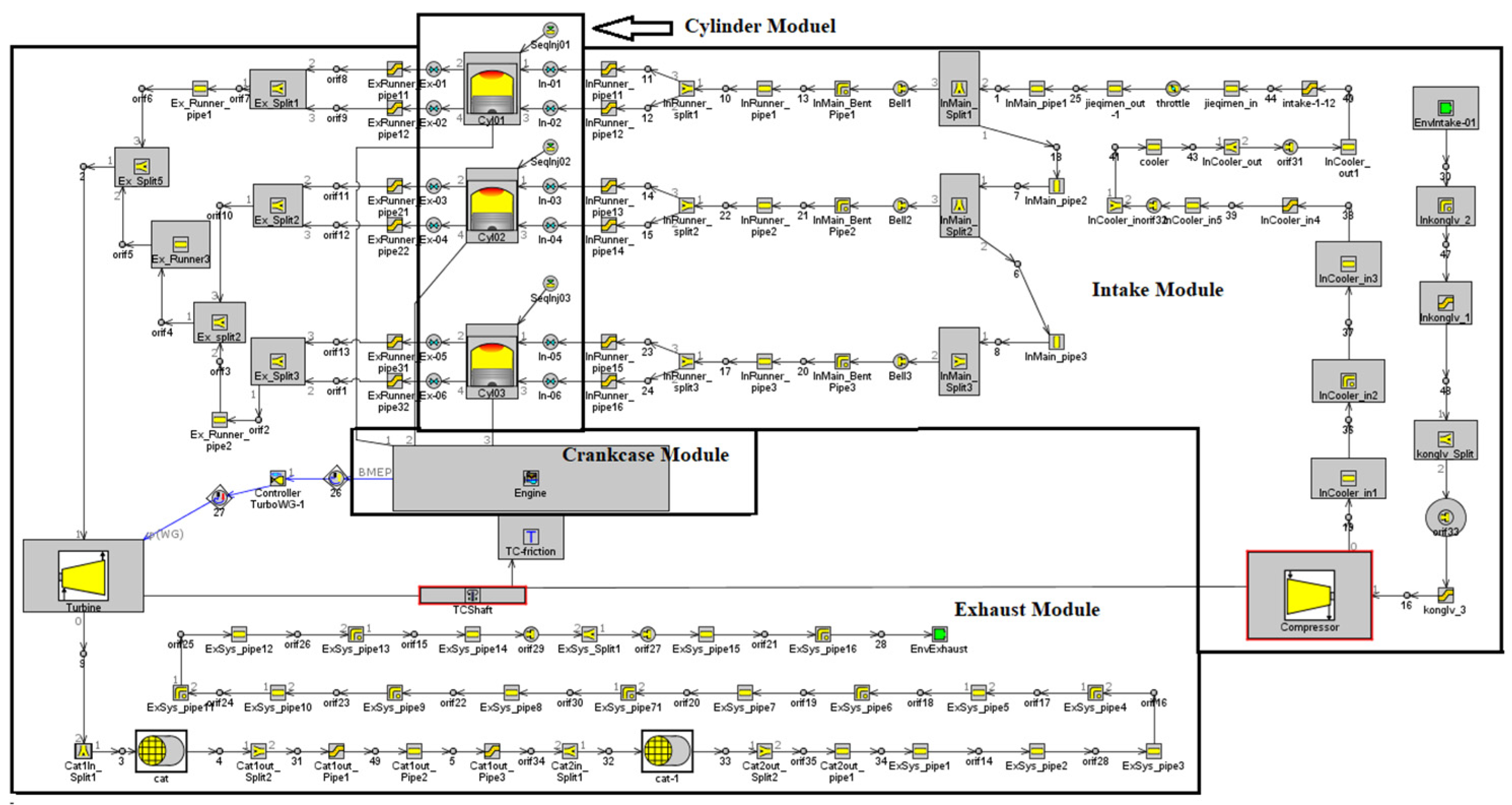
Figure 1. One-dimensional simulation model of ammonia-hydrogen engine.
Energies 17 02337 g001
Figure 2. CHEMKIN simulation model validation: (a) XH2 = 0%; (b) XH2 = 40%, the volume fraction of hydrogen is 40%.
Energies 17 02337 g002
Figure 3. Fitting results of laminar flame velocity under different hydrogen blending ratios: (a) EH2 = 0%; (b) EH2 = 12%; (c) EH2 = 23%; (d) EH2 = 46%.
Energies 17 02337 g003aEnergies 17 02337 g003b
Figure 4. Comparison of simulated and experimental cylinder pressure and combustion heat release rate: (a) EH2 = 0%; (b) EH2 = 12%; (c) EH2 = 23%; (d) EH2 = 46%.
Energies 17 02337 g004
Figure 5. Sensitivity analysis diagram of ignition delay.
Energies 17 02337 g005
Figure 6. Cylinder pressure and combustion heat release rate: (a) cylinder pressure; (b) combustion heat release rate.
Energies 17 02337 g006
Figure 7. Ignition delay and combustion duration: (a) ignition delay; (b) combustion duration.
Energies 17 02337 g007
Figure 8. Different blending ratios correspond to BTE and combustion phase (BMEP = 15 bar): (a) BTE at 1500 r/min; (b) combustion phase at 1500 r/min; (c) BTE at 2500 and 3500 r/min; (d) combustion phase at 2500 and 3500 r/min.
Energies 17 02337 g008
Figure 9. BTE and combustion phase fuel at high speed (EH2 = 46%): (a) BTE; (b) combustion phase.
Energies 17 02337 g009
Figure 10. BTE corresponds to different blending ratios (BMEP = 10 bar): (a) BTE at 1500 r/min; (b) BTE at 2500 and 3500 r/min.
Energies 17 02337 g010
Figure 11. BTE corresponding to different blending ratios (BMEP = 20 bar): (a) BTE at 1500 r/min; (b) BTE at 2500 and 3500 r/min.
Energies 17 02337 g011
Table 1. Main technical parameters of the engine.
ParametersValue
Number of cylinders3
Hydrogen supply modeDirect injection
Ammonia supply modePort injection
Valve timing mechanismDual variable valve timing
Bore diameter × stroke (mm)83 × 92
Connecting rod length (mm)144.3
Displacement (L)1.493
Compression ratio11.3
Rated power (kW)108.43
Rated speed (r/min)5500
Fuel consumption (g/(kW·h))320.82
Table 2. Correspondence between different hydrogen blending ratios.
Energy Ratio of HydrogenMass Ratio of HydrogenVolume Ratio of Hydrogen
000
12%2.09%16.31%
23%4.47%29.92%
46%11.77%54.90%
Table 3. Fitting results of fractional equations with different hydrogen blending ratios.
Hydrogen-Blending RatioPolynomial Fitting ResultsFractional Fitting Results
EH2 = 0% S L 0 = 7.51 30.19 φ 1.186 2 S L 0 = 0.1143 φ 2 + 0.8647 φ φ 2 2.173 φ + 1.325
EH2 = 12% S L 0 = 10.68 46.05 φ 1.175 2 S L 0 = 0.5899 φ 2 + 2.368 φ φ 2 2.246 φ + 1.44
EH2 = 23% S L 0 = 18.91 57.37 φ 1.14 2 S L 0 = 1.31 φ 2 + 6.092 φ φ 2 2.093 φ + 1.36
EH2 = 46% S L 0 = 49.65 138.5 φ 1.158 2 S L 0 = 12.77 φ 2 + 28.04 φ φ 2 2.356 φ + 1.691
Table 4. Simulated condition setting.
ParametersValue
Hydrogen blending ratio0%, 12%, 23%, 46%
Engine speed (r/min)1500~5500
BMEP (bar)10, 15, 20
Equivalent ratio1
Table 5. The elementary reaction has a strong influence on the ignition delay.
Primitive Reaction NumberElementary Reaction Equation
R1H + O2 = O + OH
R2O + H2 = OH + H
R3O + H2 = OH + H
R4OH + H2 = H + H2O
R16H + O2(+M) = HO2(+M)
R58NH2 + H = NH + H2
R60NH2 + O = HNO + H
R61NH2 + O = HNO + H
R63NH2 + HO2 = H2NO + OH
R64NH2 + HO2 = NH3 + O2
R68NH2 + NO = NNH + OH
R69NH2 + NO = N2 + H2O
R70NH2 + NO = N2 + H2O
R103N2H3(+M) = N2H2 + H(+M)
R161NH3 + H = NH2 + H2
R162NH3 + OH = H2O + NH2
R164NH3 + O = NH2 + OH
R219H2NO + NH2 = HNO + NH3
R220H2NO + HO2 = HNO + H2O2
Disclaimer/Publisher’s Note: The statements, opinions and data contained in all publications are solely those of the individual author(s) and contributor(s) and not of MDPI and/or the editor(s). MDPI and/or the editor(s) disclaim responsibility for any injury to people or property resulting from any ideas, methods, instructions or products referred to in the content.