Abstract
Mortise and tenon are very important parts of gas turbine dealing operation safety. Additionally, the temperature distribution of the turbine blade and disk is affected by the heat transfer characteristics in its gap. Then, the S-shaped mortise and tenon gap were numerically studied under rotating conditions, and the flow and heat transfer characteristics were analyzed. First, the heat transfer coefficient (HTC) of the mortise and tenon surfaces was measured with thermochromic liquid crystal. Then, the numerical method was verified using the test results, and the grid independence analysis was conducted. Finally, the flow and heat transfer characteristics of the gap under static and rotating conditions were numerically studied, five different Reynolds numbers (Re = 15,000, 20,000, 25,000, 30,000, 35,000) and five gap widths (d = 1 mm, 1.5 mm, 2 mm, 2.5 mm, 3 mm) were conducted and analyzed in detail. The results show that, under the rotating condition, the pressure distribution in the gap is different from that of the static condition; the pressure increases along the radial direction due to the action of centrifugal force and reaches its maximum value at the corner of the “S” shaped structure. With the increase in Re, the heat transfer intensity of the gap increases gradually. Additionally, the heat transfer intensity of the gap increases with an increase in its width.
1. Introduction
During the assembly of the gas turbine blade tenon and mortise, an S-shaped gap will form, and the cold air in the disk cavity will flow downstream through the gap due to the differential pressure between both sides of the disk. The flow and heat transfer characteristics of the gap will affect the temperature distribution of the blade and disk. In order to obtain a more accurate temperature field of the gas turbine blade and disk and to ensure the safe operation of the gas turbine, it is necessary to carry out a more in-depth study on the flow and heat transfer characteristics in the mortise and tenon assembly gap.
Early studies on tiny channels, such as mortise and tenon assembly gaps, were mainly based on simplified models. These studies focused on channels with regular shapes such as round, triangular, rectangular, circular, and so on. As early as the 1940s, Walker et al. [1] have studied the flow characteristics in the cross-section of regular channels with non-circular shapes. Xu et al. [2] investigated the flow resistance of the liquid in the microchannel at a certain Reynolds number (Re) using experimental methods. Lee et al. [3] experimentally investigated the heat transfer characteristics in a rectangular microchannel. Sun et al. [4] investigated the heat transfer characteristics in a rectangular microchannel of aero-engine turbine blades with a hydrodynamic diameter of 1 mm. Hetsroni et al. [5,6] investigated the pressure loss of microchannels with different cross-sectional shapes, such as circular, rectangular, triangular, and trapezoidal microchannels, as well as the effects of geometry, axial heat flow density due to heat conduction, and energy dissipation for a small Mach number. Kose et al. [7] numerically investigated three different shapes (rectangular, triangular, and trapezoidal) of microchannels using Computational Fluid Dynamics. In this study, minimization of power consumption and enhancing heat transfer were obtained with rectangular microchannel. Roy et al. [8] adopted a numerical simulation method and took a small channel as the research object. By changing the rotational speed, hydraulic diameter, and aspect ratio, they studied how these parameters affected the rotational Re and, thus, the development of secondary flow. Avramenko et al. [9] considered the heat transfer problem of incompressible flow in rotating microchannels under the first and second-order slip boundary conditions. These studies on simplified models show that the heat transfer varies along the flow direction and increase with an increase in Re.
However, because of the unique geometry of the mortise and tenon assembly gap structure, the flow and heat transfer characteristics are different from that of the simplified model. Liu et al. [10] transformed the heat transfer process in the mortise and tenon assembly gap between the turbine blade and disk into a convective heat transfer process when analyzing the blades of a gas turbine high-pressure turbine. Duan et al. [11] used an actual gas turbine mortise and tenon gap as the research object, enlarging it three times, and conducted experimental research on the flow characteristics of the S-shaped mortise and tenon assembly gap structure. It is demonstrated that the discharge coefficient of the channel of the S-shaped mortise and tenon assembly gap is connected not only to the Re, but also to the exit Mach number at the channel outlet. Ma et al. [12] enlarged an actual gas turbine S-shaped mortise and tenon assembly gap structure nine times and measured the gap heat transfer coefficient (HTC) using thermochromic liquid crystal. The experimental results showed that the HTC gradually decreases with the development direction of the flow while increasing with the increase in the Re. Chang et al. [13,14] conducted an experimental study on the fir-tree-type mortise and tenon assembly gap structure, and the results showed that there is no obvious turning point from laminar flow to turbulent flow due to the complex three-dimensional flow phenomenon in the flow process. Therefore, the complex flow and heat transfer characteristics inside the flow channel of the S-shaped mortise and tenon assembly gap cannot be simply replaced by a rectangular tube. Gopinathrao C. et al. [15] analyzed the influence of the tenon and mortise structure on the turbine disk and blade assembly of a large turbine engine using three-dimensional conjugate heat transfer analysis. These studies found that the flow and heat transfer in tenon and mortise gap is different from that of the circular and rectangular channel.
Under rotating conditions, the flow inside the channel is greatly changed compared with the static condition due to the centrifugal force and the Coriolis force. Chen et al. [16] numerically studied the flow and heat transfer characteristics of typical S-shaped and double crescent-shaped mortise and tenon assembly gaps under static and rotating conditions. The results showed that the double S-shaped channel has a channel vortex on the left branch of the mortise and tenon gap, and its size was affected by the Re and the rotation number. However, there is no channel vortex in the right branch in any Re and rotation number. The rotation has no significant effect on the averaged HTC of the leading and trailing surfaces of the double S channel. The surface HTC increases with increasing Re. In the double crescent-shaped channel, the right wall of the channel has a higher local HTC under rotating conditions. Sohankar et al. [17] numerically investigated the features of flow fluid and convective heat transfer in a rotating rectangular U-shaped microchannel for various aspect ratios (AR). It is found that the total Nusselt number is higher for the constant wall temperature case than that of the constant heat flux case in a rotating microchannel, while it is contrary in stationary one. Shi et al. [18] researched the influence of rotation on the aerothermal characteristics of the channel. Rotation makes the structure of the longitudinal vortex reinforced using centrifugal force at the turning region corner. Li and Yan et al. [19,20] examined the effect of rotation on jet impingement cooling by conducting experiments. The results show that the rotational Coriolis force is the dominant factor that affects the cooling of rotating jet impingement, while the buoyancy force can affect heat transfer at high rotation numbers. Cheng et al. [21] numerically and experimentally studied the heat transfer and pressure loss in a three-pass serpentine channel with trailing bleed holes. The experiments indicate that, compared with non-rotating conditions, the rotation effects show a more appreciable influence on the heat transfer enhancement values along the serpentine channel than the channel Reynolds numbers. Liang et al. [22] investigated the turbulent flow and heat transfer characteristics in the rotating L-shaped and wedged channel. At the rotating rate of 400 rpm, compared to the stationary condition, both the maximum deviations of the Nusselt number and the pressure losses on the trailing and leading end walls are reduced.
Under rotating conditions, the flow coefficient decreases due to the influence of centrifugal force, pressure gradient, and Coriolis force. Additionally, rotation may cause the average heat transfer surface to be higher than that under static conditions. Armellini et al. [23] conducted experimental research on the flow field characteristics in the trailing edge slot of the turbine blade under both static and rotating conditions. Wei et al. [24] numerically simulated the flow and heat transfer process of eccentric and rotating straight-through labyrinth seals. The research results showed that when the Taylor number is greater than 34.2, the leakage coefficient decreases slightly with the increase in rotating speed. Dring et al. [25] investigated the effect of inlet turbulence intensity and the interaction between the rotor and stator on the heat transfer characteristics of a large-scale rotating turbine model. Su et al. [26] numerically investigated the heat transfer characteristics and turbulent flow in the asymmetric snake-like inner cold channel model of a turbine rotor under rotating conditions. The results showed that the asymmetry factors and rotation factors provide the variations in the heat transfer characteristics of each wall, while the finned structure and rotation factors generate the transverse secondary flow in the channel, which increases the total heat transfer capacity. Willett et al. [27] found that rotation has an important effect on the flow state of the channel. Due to the change in the flow state, the heat transfer of the rotating channel also changes. Saravani et al. [28] studied the combined effects of Reynolds number and rotational effect for a two-pass channel with a 180-deg turn numerically and experimentally. From the results, it can be concluded that increasing both Reynolds number and rotational speed is in favor of the heat transfer coefficient enhancement, especially in the turn region. Meng et al. [29] experimentally and numerically investigated the film cooling performance on the pressure side of turbine blades at a rotating speed of 600 rpm. It can be seen that the coolant coverage is poor near the tip due to the rotating effect on the upstream of the pressure side.
It can be concluded from the previous study that researchers mostly studied regular microchannels; few studies focused on irregular channels such as mortise and tenon assembly gap. Meanwhile, because of the centrifugal force, Coriolis force, and other complex affecters, the flow and heat transfer characteristics inside the microchannel under rotating conditions would differ from those under static conditions. However, the study on the effects of flow and structural parameters on the flow and heat transfer inside the mortise and tenon assembly gap under rotating conditions is incomplete. Hence, this paper focuses on the mortise and tenon gap of a gas turbine rotor blade, and the effects of Re and width of the gap on the flow and heat transfer characteristics under rotating conditions were studied. The findings of this study provide valuable references for the accurate design of the secondary air system in gas turbines.
2. Physical Model and Computational Method
2.1. Physical Model
Figure 1a is an assembly physical map of the blade and turbine disk. The S-shaped mortise and tenon gap, marked by the red circle in Figure 1b, is at the connection between the turbine disk and the blade. Figure 1c shows the computational model used in the calculations, consisting of an inlet chamber, an outlet chamber, and the intermediate mortise and tenon gap channel. The parameters of the model are shown in Table 1. Figure 2 illustrates the locations of particular parameters. The leading and trailing surfaces in this paper refer to the left and right sides of the mortise and tenon channel, with the view direction being the outlet direction of the channel. Both of them are marked with blue arrows in Figure 2. The distance r between the model and the axis of rotation is 400 mm.

Figure 1.
Physical model (a) Assembly physical map of blade and turbine disk; (b) S-shaped mortise and tenon gap position diagram; (c) Numerical calculation model.

Table 1.
Geometry parameters of mortise and tenon gap channel.
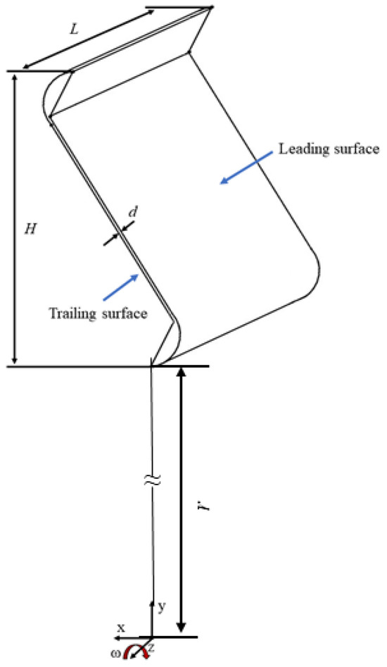
Figure 2.
Schematic diagram of mortise and tenon gap.
2.2. Governing Equations
The solved governing equations are shown in Equations (1)–(3).
Continuity equation:
where represents the fluid density; represents the velocity vector of fluid.
Momentum equation:
where , represents the mass force and surface force acting on the fluid surface. The expression of :
where represents the stress component of each direction.
Energy equation:
where represents heat flux; e represents internal energy per unit volume of fluid.
2.3. Boundary Conditions
The inlet boundary condition is set as a mass flow inlet, and the mass flow rate determined by the inlet Re (Re = 1.5 × 10⁴, 2 × 10⁴, 2.5 × 10⁴, 3 × 10⁴, 3.5 × 10⁴), the inlet temperature Th is 573.15 K; the outlet has an average static pressure corresponding to standard atmospheric pressure; the mortise and tenon gap walls are given a constant wall temperature with 673.15 K; all other walls are considered adiabatic and no-slip surfaces. The rotational speed of the entire computational domain is 3000 rpm.
2.4. Turbulence Model Validation
Experiments were carried out on a model of gas turbine blade mortise and tenon assembly gap. The experimental system diagram is shown in Figure 3, consisting of the main flow system, experimental section, and data acquisition system. The mainstream is supplied by a screw compressor (0.7 MPa, 0.4 kg/s), and the gas passes through a refrigerant dryer, a filter, a storage tank, a heater, a mass flowmeter, and then into the experimental section, which is constructed using assembled acrylic glass plates connected with bolts. The data acquisition system is responsible for collecting information on liquid crystal color changes, temperature variations, and pressure changes. The measuring instruments required in this paper include: pressure scanning valve, mass flowmeter, T-type thermocouple, USB industrial camera, and so on.
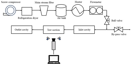
Figure 3.
Schematic diagram of the experimental system.
Since the thermochromic liquid crystal (TLC) measurement method is used in this paper, the heat transfer characteristics test was conducted with a five times enlarged mortise and tenon assembly gap. The image of the test rig is shown in Figure 4. During the test, take an RGB color image and convert it to HIS tone image to determine temperature. So, TLC was calibrated before the test. According to Moffat [30], The uncertainty of HTC measurement is shown in Table 2.
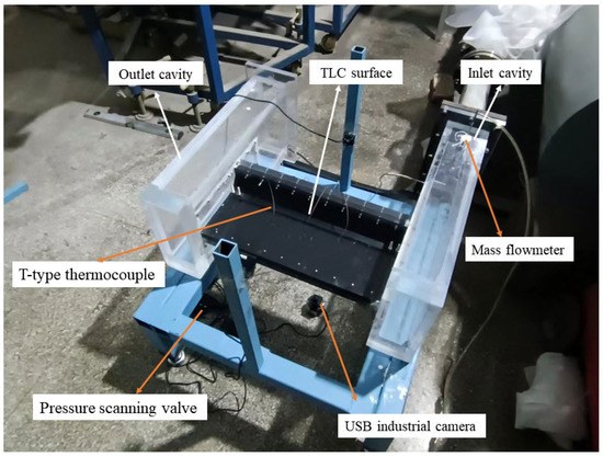
Figure 4.
Physical image of the test rig.
Table 2.
Uncertainty of TLC measurement.
The commercial software ANSYS CFX 2020 R1 was used for numerical simulation. The accuracy of the prediction is significantly influenced by the turbulence model. In order to select a suitable turbulence model, the numerical calculated circumferentially averaged Nusselt number (Nucir) of the four turbulence models (standard k-ε model, RNG k-ε model, standard k-ω model, and SST k-ω model) were compared with the experimental results. Nusselt number (Nu) can be defined as:
where qw is the average convective heat flux, Tw and Th are the average temperatures of the surface and fluid, respectively; λ is the thermal conductivity of hot air. Dh is hydraulic diameter, which is defined as:
where A is the mortise and tenon channel cross-sectional area, and P is the mortise and tenon channel cross-sectional perimeter. Their values are about 1.2 mm2 and 5.0 mm, respectively.
The Nucir is defined as:
where Nui is the Nu value of the corresponding grid node (i); li is the length of the grid node (i).
Figure 5 compares the distribution of Nucir along the flow direction between the numerical calculations and experimental measurements. The Z in Figure 5 refers to the Z-axis in the coordinate system, which is parallel to the flow direction. The SST k-ω turbulence model’s prediction of Nucir, as illustrated in Figure 5, exhibits the greatest agreement with the experimental results. Therefore, the SST k-ω turbulence model is chosen for all subsequent calculations.
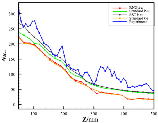
Figure 5.
Nucir distribution of numerical calculations and experimental results.
2.5. Grid Generation and Grid Independence Analysis
The computational domain uses unstructured grids generated by commercial software ICEM CFD 2020 R1. The near-wall grids are refined, with a y+ < 1 within the calculated range of Res. The growth rate of the grids is set to 1.1.
To ensure the accuracy of the computational results with minimum computational resources, three grids with 3 million, 5.8 million, and 9.2 million cells were selected for grid independence verification. Figure 6 shows the distribution of Nucir on the trailing surface for different grid numbers. It can be observed that when the grid number is larger than 5.8 million, Nucir remains almost unchanged. Considering the grid quantity, computational accuracy, and computational time, the grid number of 5.8 million was determined for this study.
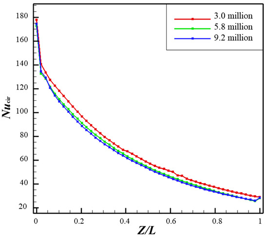
Figure 6.
Distribution of circumferential average Nusselt number (Nucir) on the trailing wall.
3. Results and Discussion
3.1. Effect of Rotation
The effect of Re (on flow and heat transfer characteristics of the mortise and tenon gap under rotating conditions was studied, and four Re = 1.5 × 10⁴, 2 × 10⁴, 2.5 × 10⁴, 3 × 10⁴, 3.5 × 10⁴) were conducted.
Re can be defined by the formula:
where ρ is the air density, u is the inlet air velocity, μ is the hydrodynamic viscous coefficient.
3.1.1. Effect of Rotation on Flow Characteristics
Figure 7 shows the pressure distribution at Z/L = 0.5 under static and rotating conditions. The black arrow represents the direction of the pressure difference. It can be observed that under the rotating condition, the pressure distribution is different from that in the static condition. The pressure increases in the radial direction due to the centrifugal force, reaching its maximum value at the corner of the S-shaped mortise and tenon structure.
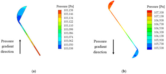
Figure 7.
Pressure distribution contour at Z/L = 0.5 (Re = 1.5 × 10⁴, d = 0.6 mm) (a) Under static conditions; (b) Under rotating conditions.
Figure 8 shows the dimensionless velocity contour and streamline distribution at the upper and lower portions of the mortise and tenon gap under static and rotating conditions at Z/L = 0.0 (near the inlet), Z/L = 0.5 (middle of the channel), and Z/L = 1.0 (near the outlet), respectively. The black arrows represent the flow direction at the narrow channel of the S-shaped gap, the blue arrows represent the direction of the centrifugal force, and the green arrows represent the direction of the pressure gradience. The direction of rotation has been labeled in the figure. From Figure 8, it can be seen that, in both conditions, at any cross-section of the channel, a certain number of channel vortices are generated at both ends of the mortise and tenon gap due to the larger flow space of the circular cavities at both ends. At the straight, narrow gap of the channel, the flow velocity is low due to the viscous effect of the fluid, resulting in larger flow losses. The formation of inlet vortices can be observed at the inlet of the mortise and tenon gap, indicating significant friction losses at this location. The size of the channel vortices is smallest at the outlet of the channel, resulting in a gradual decrease in drag losses along the flow path. Under rotating conditions, compared to static conditions where the fluid is affected only by the pressure difference, the fluid flow becomes more complex due to the combined effects of the centrifugal force generated by rotation.
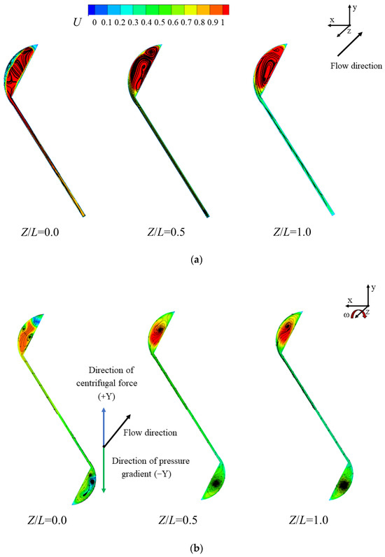
Figure 8.
Dimensionless velocity contour and streamline distribution of the mortise and tenon structure channel (Re = 3.5 × 10⁴, d = 0.6 mm) (a) Under static conditions; (b) Under rotating conditions.
The fluctuating value of fluid turbulence velocity is an important parameter that affects the distribution of HTC. The definition of turbulence intensity is:
where k is turbulent kinetic energy and is the mean velocity.
Figure 9 illustrates the fluid turbulence intensity contour at Z/L = 0.0 (near the inlet), Z/L = 0.5 (middle of the channel), and Z/L = 1.0 (near the outlet) for the mortise and tenon gap. Because the rotation changes the incident direction of the fluid, the inlet vortex at the inlet of the channel (Z/L = 0.0) is more complex, so the turbulence intensity at the inlet is higher, and the presence of the vortex leads to a more intense mixing of the fluid. As the fluid flows to the middle of the channel (Z/L = 0.5), the turbulence intensity decreases noticeably compared to the inlet, and the turbulence intensity gradually decreases as the fluid flows downstream.
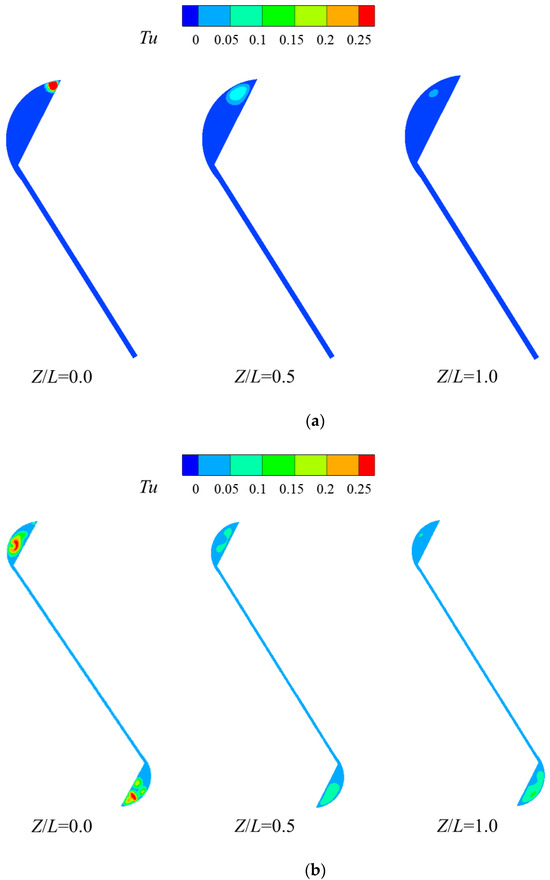
Figure 9.
Turbulence intensity distribution contour at different cross-sections of the mortise and tenon gap (Re = 3 × 10⁴, d = 0.6 mm) (a) Under static conditions; (b) Under rotating conditions.
3.1.2. Effect of Rotation on Heat Transfer Characteristics
Figure 10 and Figure 11 illustrate the Nu distribution contours on the leading and trailing surfaces of the mortise and tenon gap under static and rotating conditions for different Res, respectively. As illustrated in Figure 8, the rotating effect encouraged the formation of a vortex within the channel, resulting in an increase in turbulence within the entire gap (Figure 9), as well as an improvement in the heat exchange between the gap wall and cooling air. Local Nu is larger at the channel inlet under the rotating condition than in the static condition because the fluid is subjected to higher intensity consumption vortices and turbulence at the inlet. At the same time, the presence of vortices within the larger space (upper and lower corner) of the mortise and tenon gap enhances the local heat transfer. Meanwhile, Nu in the middle narrow slot part of the channel is reduced because the advantageous vortices produced in both the static and rotating conditions are smaller. At the outlet of the channel, the size and number of vortices generated under static and rotating conditions are both reduced. As a result, Nu is gradually reduced along the axial direction, consistent with the analysis results in Figure 8. Under rotating conditions, the magnitude of channel vortices in the top half of the channel is larger than that in the lower half due to the effect of centrifugal force. Thus, the heat transfer in the upper half of the channel is larger.
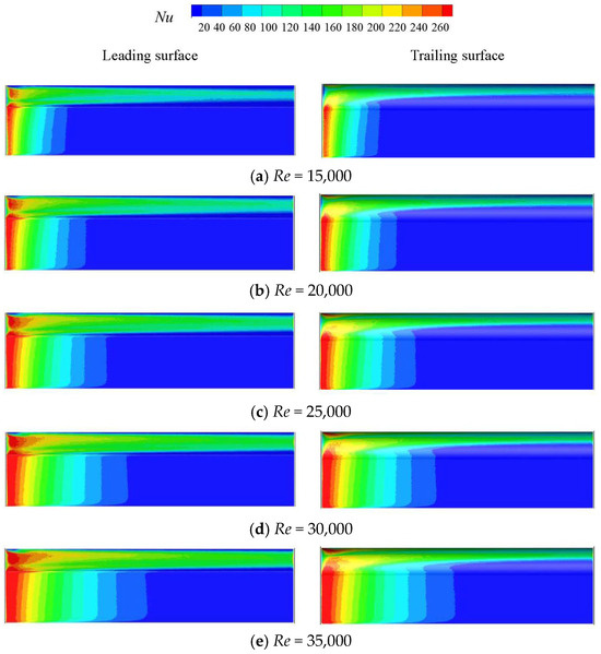
Figure 10.
Contours of Nu distribution on the leading and trailing surfaces for different Res under static conditions (d = 0.6 mm).
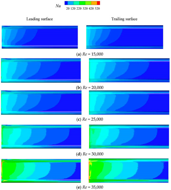
Figure 11.
Contours of Nu distribution on the leading and trailing surfaces for different Res under rotating conditions (d = 0.6 mm).
The globally averaged Nu (Nuave) distributions of the leading and trailing surfaces under static and rotating conditions for different Res are given in Figure 12. The Nuave is defined as:
where Nui,j is the Nu of the corresponding grid node (i, j), Ai,j is the area controlled by node (i, j), Aw is the heat transfer wall area.
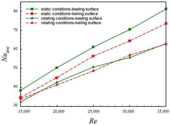
Figure 12.
Distribution of average Nusselt number (Nuave) on the leading and trailing surfaces under rotating and static conditions for different Res.
From Figure 12, in both static and rotating conditions, it is evident that in both static and rotating conditions, the Nuave rises as Re rises, which is consistent with the results analyzed in Figure 10 and Figure 11. Higher Re corresponds to a higher inlet mass flow rate. As the amount of cold air increases, the gap wall cools more thoroughly, and the Nuave of the wall increases. Under the rotating condition, there is little difference in the heat transfer intensity between the leading and trailing surfaces. However, the Nuave of both the leading and trailing surfaces in the rotating condition is lower than that of the static condition, which may be caused by the centrifugal force of rotation, which leads to more airflow downstream on the upper side and decreases the down part heat transfer intensity.
3.2. Effect of the Gap Width
The effect of five gap widths on the flow and heat transfer characteristics of the mortise and tenon assembly gap under rotating conditions was studied, in which five different widths (d = 0.2 mm, 0.3 mm, 0.4 mm, 0.5 mm, 0.6 mm) were analyzed in detail.
3.2.1. Effect of the Gap Width on Flow Characteristics
Figure 13 shows the dimensionless velocity contours and flow streamline distributions at Z/L = 0.0 (near inlet), Z/L = 0.5 (middle of the channel), and Z/L = 1.0 (near outlet) of the mortise and tenon gap under rotating conditions with a gap width of d = 0.2 mm. Additionally, the results in the same positions and conditions with a gap width of d = 0.6 mm have been shown in Figure 8b. The black arrows represent the flow direction of the S-shaped channel, the blue arrows represent the direction of the centrifugal force, and the green arrows represent the direction of the pressure gradience. The direction of rotation has been labeled in the figure. As can be seen in Figure 8 and Figure 13, the flow pattern with different gap sizes is almost the same. The only difference is the velocity magnitude in the lower crescent corner of the narrower gap is larger, while the velocity magnitude in the straight slot of the narrower gap is lower, especially at the inlet portion. One reason for that is the air velocity decreases with the gap width expands since all cases are kept consistent in Re, and the hydraulic diameter of the gap increases with the gap width. Another reason for that is the effect of the wall on the flow will be more notable in a narrower slot.
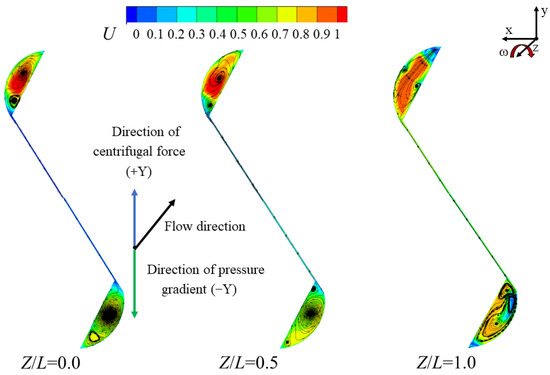
Figure 13.
Dimensionless velocity contours and streamline distributions in the mortise and tenon gap channel under rotating conditions (d = 0.2 mm).
Figure 14 demonstrates the fluid turbulence intensity contours of the mortise and tenon gap at Z/L = 0.0 (near the inlet), Z/L = 0.5 (middle part of the channel), and Z/L = 1.0 (near the outlet) with a gap width values, 0.5. Additionally, the turbulence intensity in the same positions and conditions with a gap width of d = 0.6 mm is shown in Figure 9b. It can be seen that the variation of turbulent intensity within the structure channel follows the same pattern as analyzed in Figure 9. Meanwhile, the magnitude of the turbulence intensity increases with the gap width.
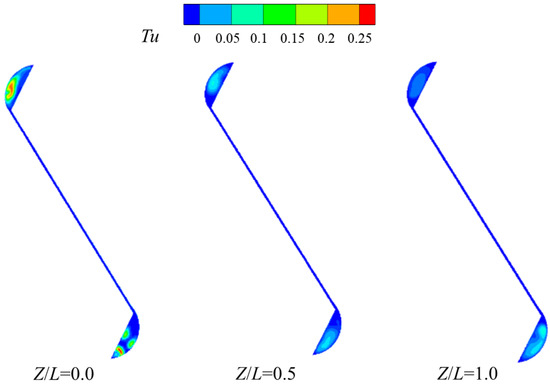
Figure 14.
Turbulent intensity distribution contours at different cross-sections within the mortise and tenon gap (d = 0.5 mm, Re = 3.5 × 10⁴).
3.2.2. Effect of the Gap Width on Heat Transfer Characteristics
Figure 15 illustrates the contours of the leading and trailing surfaces’ Nu distributions for different mortise and tenon assembly gap widths under rotational conditions. The case where d = 0.6 mm is shown in Figure 11e. In comparison with Figure 11e, the reduction in the gap width of the channel causes a decrease in the area of the high Nu area on the channel wall, and this phenomenon is more obvious in the narrow straight slot potion. These findings are consistent with the phenomenon shown in Figure 13. Additionally, the reasons to explain that have been discussed while analyzing Figure 13; the main reason is that the velocity magnitude and turbulence intensity increase with the gap width.

Figure 15.
Contours of Nu distribution on the leading and trailing surfaces for different mortise and tenon assembly gap widths under rotational conditions (Re = 3.5 × 10⁴).
Figure 16 shows the distribution of Nuave on the leading and trailing surfaces for different mortise and tenon assembly gap widths under rotating conditions. From the figure, it can be seen that the channel Nuave increases with the increase in the mortise and tenon assembly gap width. In the rotating condition, the vortex size of the channel near the leading surface is slightly larger than that of the trailing surface. Therefore, the heat transfer between the fluid and the leading surface is slightly stronger than compared to the trailing surface, but the difference between them is not significant. It is consistent with the analysis results in Figure 13. Consistent with Figure 15, as the channel gap width reduces, the channel Nuave falls, and the Nuave difference between the leading and trailing surfaces increases.
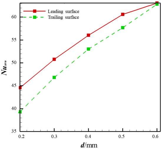
Figure 16.
Distribution of Nuave on the leading and trailing surfaces for different mortise and tenon assembly gap widths under rotating conditions (Re = 3.5 × 10⁴).
4. Conclusions
This paper numerically investigated the effects of rotation and assembly gap width on the flow and heat transfer characteristics within the mortise and tenon gap. The flow and heat transfer in static and rotating conditions with five Re were discussed, and five gap widths in rotating conditions were analyzed. The main conclusions are as follows:
- Under rotating conditions, the pressure distribution across the mortise and tenon assembly gap section differs from that in static conditions. The pressure increases in the radial direction due to centrifugal force, reaching its maximum value at the corners of the S-shaped structure. The combined effects of centrifugal force and pressure gradience result in a different distribution of the streamlines in the upper and lower halves of the channel cross-section. The rotation changes the incident direction of the fluid, and the inlet vortex becomes more complicated, resulting in a higher turbulence intensity at the inlet. As the flow progresses, the turbulence intensity gradually decreases.
- Due to the presence of the inlet vortex, the drag coefficient and Nu of the mortise and tenon assembly gap are highest at the channel inlet. As the flow develops, both of them gradually decrease. In the same cross-section of the channel, with the affected viscosity of the fluid and spacing between the wall, velocity magnitude, and the turbulence intensity, the crescent-shaped corner region with a wider flow area at the two ends of the mortise and tenon assembly gap is larger, and exhibits higher Nu values, while those values in the narrower straight slot area are lower.
- The Nuave of both the leading and trailing surfaces in the rotating condition are lower than that of the static condition, which may be caused by the centrifugal force of rotation, which leads to more airflow downstream on the upper side and decreases the down part heat transfer intensity. With the increase in Re and the width of the mortise and tenon assembly gap, the wall Nuave increases, indicating higher heat transfer intensity in the channel. While the effect of Re and gap width are more announced than the rotation.
Author Contributions
Conceptualization, R.S. and Z.L.; methodology, Z.L. and R.S.; software, Z.L. and Y.X.; validation, Y.X. and Z.L.; formal analysis, Y.X.; investigation, Y.X. and Z.L.; resources, Z.F.; data curation, Y.X.; writing—original draft preparation, Y.X.; writing—review and editing, Z.L.; visualization, Z.F. and Z.L.; funding acquisition, Z.L. All authors have read and agreed to the published version of the manuscript.
Funding
This work was supported by the National Science and Technology Major Project (J2019-III-0007-0050).
Data Availability Statement
The data presented in this study are available on request from the corresponding author. The data are not publicly available due to privacy.
Conflicts of Interest
The authors declare no conflicts of interest.
References
- Walker, J.E.; Whan, G.A.; Rothfus, R.R. Fluid friction in noncircular ducts. AICHE J. 1957, 3, 484–489. [Google Scholar] [CrossRef]
- Xu, B.; Ooti, K.T.; Wong, N.T.; Choi, W.K. Experimental investigation of flow friction for liquid flow in microchannels. Int. Commun. Heat Mass Transf. 2000, 27, 1165–1176. [Google Scholar] [CrossRef]
- Lee, P.S.; Garimella, S.V.; Liu, D. Investigation of heat transfer in rectangular microchannels. Int. J. Heat Mass Transf. 2005, 48, 1688–1704. [Google Scholar] [CrossRef]
- Haofeng, S.; Jining, S. Experimental Study on Flow and Heat Transfer of Rectangular Microchannels on Rotating State. Aeroengine 2013, 39, 5. [Google Scholar]
- Hetsroni, G.; Mosyak, A.; Pogrebnyak, E.; Yarin, L.P. Heat transfer in micro-channels: Comparison of experiments with theory and numerical results. Int. J. Heat Mass Transf. 2005, 48, 5580–5601. [Google Scholar] [CrossRef]
- Hetsroni, G.; Mosyak, A.; Pogrebnyak, E.; Yarin, L.P. Fluid flow in micro-channels. Int. J. Heat Mass Transf. 2005, 48, 1982–1998. [Google Scholar] [CrossRef]
- Kose, H.A.; Yildizeli, A.; Cadirci, S. Parametric study and optimization of microchannel heat sinks with various shapes. Appl. Therm. Eng. 2022, 211, 118368. [Google Scholar] [CrossRef]
- Roy, P.; Anand, N.K.; Banerjee, D. Numerical simulation of flow and heat transfer in radially rotating microchannels. Microfluid. Nanofluidics 2013, 15, 397–413. [Google Scholar] [CrossRef]
- Avramenko, A.A.; Dmitrenko, N.P.; Shevchuk, I.V.; Tyrinov, A.I.; Shevchuk, V.I. Heat transfer of incompressible flow in a rotating microchannel with slip boundary conditions of second order. Int. J. Numer. Methods Heat Fluid Flow 2018, 29, 1786–1814. [Google Scholar] [CrossRef]
- Yongbao, L.; Youlong, F. The Finite Element Analysis for HPT Blade Tip Clearance Variation of Gas Turbine. Chin. J. Ship Res. 2011, 6, 5. [Google Scholar]
- Yufa, D.; Li, Z.; Haiying, L.; Xinglai, L. Experimental Investigation on Flow Characteristics in Tenon Joint Gap Between Turbine Blade and Disk. Mach. Electron. 2014, 2, 7–10. [Google Scholar]
- Xiaoteng, M.; Zheng, C.; Duchun, X. Flow and Heat Transfer Characteristics of the ‘‘S’’ type Assembly Clearance. J. Eng. Thermophys. 2016, 37, 1721–1727. Available online: https://kns.cnki.net/kcms2/article/abstract?v=lWc4gvQ5J15Xx4UmkyIBR53VmiCL_f-_65_-unt05NfdD1KkEyccTJ-CBmwGHDAbDcIz2Hi5xVI5dyYHeCurn6kXgh5OPGS8gy4kt4zuqTHHfvutFR-3EqEKpfDbyy81&uniplatform=NZKPT&language=CHS (accessed on 6 November 2023).
- Haiping, C.; Taiping, H.; Yansheng, Y. An experimental study on fluid friction and heat transfer in complex noncircular passages. J. Aerosp. Power 1993, 8, 358–362. [Google Scholar]
- Haiping, C.; Taiping, H.; Wanping, C. Experimental investigation on flow and heat transfer characteristics in tenon joint gap between turbine blade and disk. Trans. Nanjing Univ. Aeronaut. Astronaut. 1995, 5, 52–56. [Google Scholar]
- GopinathraoC, N.; AlizadehD, M.; Clarkson, J. Conjugate heat transfer study of a spin pit rig: Application to the lifing of hp turbine disc firtrees. In Proceedings of the ASME Turbo Expo 2008: Power for Land, Sea, and Air, Berlin, Germany, 9–13 June 2008; pp. 1693–1702. [Google Scholar]
- Chen, D.; Zhu, H.; Xu, Y.; Jia, X.; Liu, C.; Lu, H. Numerical Simulations of Flow Fields and Heat Transfer Characteristics in Tenon Joint Gap Between Turbine Blade and Disk under Rotating Conditions. In Proceedings of the ASME Turbo Expo: Turbomachinery Technical Conference & Exposition, Charlotte, NC, USA, 26–30 June 2017. [Google Scholar]
- Sohankar, A.; Joulaei, A.; Mahmoodi, M. Fluid flow and convective heat transfer in a rotating rectangular microchannel with various aspect ratios. Int. J. Therm. Sci. 2022, 172, 107259. [Google Scholar] [CrossRef]
- Dongbo, S.; Tao, X.; Zifeng, C.; Di, Z.; Yonghui, X. The effect of dimple/protrusion arrangements on the comprehensive thermal performance of variable cross-section rotating channels for gas turbine blades. Int. J. Therm. Sci. 2024, 196, 108733. [Google Scholar]
- Hua, L.; Hongwu, D. Heat transfer in a rotating impingement cooling channel with concave target surface. Int. J. Heat Mass Transf. 2023, 216, 124559. [Google Scholar]
- Kaixin, Y.; Hongwu, D.; Hua, L. Experimental and numerical investigation of thermo-hydraulic behavior in a rotating wedge-shaped trailing edge channel with internal jet impingement. Appl. Therm. Eng. 2023, 234, 121244. [Google Scholar]
- Yuli, C.; Yu, R.; Pengfei, S.; Longbing, H. Numerical analysis and experiments on heat transfer and flow structures in rotating three-pass serpentine channels with ribs, guide vanes and trailing bleed holes. Int. J. Therm. Sci. 2023, 193, 108529. [Google Scholar]
- Ce, L.; Yu, R.; Jianian, C.; Peng, Z. Experimental and Numerical Study of the Turbulent Flow and Heat Transfer in a Wedge-Shaped Channel With Guiding Pin Fin Arrays Under Rotating Conditions. J. Turbomach. 2022, 144, 071007. [Google Scholar]
- Armellini, A.; Casarsa, L.; Mucignat, C. Flow field analysis inside a gas turbine trailing edge cooling channel under static and rotating conditions. Int. J. Heat Fluid Flow 2011, 32, 1147–1159. [Google Scholar] [CrossRef]
- Xin, W.; Zhaohui, Y.; Feng, J.; Zhixiong, W.; Honghu, J. Numerical simulation of flow and heat transfer characteristic in straight-through labyrinth seals of aeroengines under eccentric and rotating conditions. J. Mech. Sci. Technol. 2023, 37, 3173–3183. [Google Scholar]
- Dring, R.P.; Blair, M.F.; Joslyn, H.D.; Power, G.D.; Verdon, J.M. The Effects of Inlet Turbulence and Rotor/Stator Interactions on the Aerodynamics and Heat Transfer of a Large-Scale Rotating Turbine Model. In Volume 2: Heat Transfer Data Tabulation. 15 Percent Axial Spacing; Final Report United Technologies Research Center East Hartford Ct; NASA: Washington, DC, USA, 1986. [Google Scholar]
- Su, S.; Liu, J.; An, B. Calculations of heat transfer and fluid flow in an unsymmetrical rib-roughened branch of a rotating two-pass duct. J. Eng. Thermophys. 2007, 28, 77. [Google Scholar]
- Willett, F.T., Jr. An Experimental Study of the Effects of Rotation on Convective Heat Transfer in Smooth and Pin Fin Ducts of Narrow Cross-Section. Ph.D. Thesis, Rensselaer Polytechnic Institute, Troy, NY, USA, 1999. Volume 60-09. p. 4855, Section B. [Google Scholar]
- Saravani, M.S.; DiPasquale, N.J.; Abbas, A.I.; Amano, R.S. Heat Transfer Evaluation for a Two-Pass Smooth Wall Channel: Stationary and Rotating Cases. J. Energy Resour. Technol. 2020, 142, 061305. [Google Scholar] [CrossRef]
- Long, M.; Haiwang, L.; Gang, X.; Zhi, T.; Zhiyu, Z. Film cooling performance of blade pressure side with three-row film holes under rotating condition. Int. J. Heat Mass Transf. 2022, 188, 122593. [Google Scholar]
- Moffat, R.J. Describing the uncertainties in experimental results. Exp. Therm. Fluid Sci. 1988, 1, 3–17. [Google Scholar] [CrossRef]
Disclaimer/Publisher’s Note: The statements, opinions and data contained in all publications are solely those of the individual author(s) and contributor(s) and not of MDPI and/or the editor(s). MDPI and/or the editor(s) disclaim responsibility for any injury to people or property resulting from any ideas, methods, instructions or products referred to in the content. |
© 2023 by the authors. Licensee MDPI, Basel, Switzerland. This article is an open access article distributed under the terms and conditions of the Creative Commons Attribution (CC BY) license (https://creativecommons.org/licenses/by/4.0/).