Article

Optimal Control of Brushless Doubly Fed Wind Power Generator under Zero-Voltage Ride-Through

1
School of Naval Architecture, Ocean Energy Power Engineering, Wuhan University of Technology, Wuhan 430063, China
2
State Key Laboratory of Advanced Electromagnetic Engineering and Technology, Huazhong University of Science and Technology, Wuhan 430074, China
*
Author to whom correspondence should be addressed.
Energies 2024, 17(1), 235; https://doi.org/10.3390/en17010235
Submission received: 14 November 2023 / Revised: 9 December 2023 / Accepted: 19 December 2023 / Published: 1 January 2024
(This article belongs to the Special Issue Optimal Control of Wind and Wave Energy Converters)

Abstract

:
In the grid-connected operation dynamics of brushless doubly fed generators (BDFGs), a dip in the grid voltage is equivalent to suddenly adding a reverse voltage source at the parallel node. By deriving the expressions of the transient current of power winding (PW), control winding (CW), and rotor winding (RW) of a BDFG in the complex frequency domain under a natural state, it was concluded that the overshoot and oscillation time are affected by the CW voltage, the drop degree and phase of the grid voltage, and the rotor speed. Therefore, an optimal control strategy is proposed. A state model with the CW current as the state variable was constructed using the Pontryagin minimum principle. The finite-time integral value of the square of the electromagnetic torque was set as the objective function to achieve the minimum value that could suppress the overshoot and oscillation of the electromagnetic torque, and the optimal CW voltage command value was directly solved to accelerate the convergence of the BDFG’s physical quantities, thereby reducing the amplitude. Finally, the feasibility of the optimal control algorithm was verified using tests on an experimental platform.

1. Introduction

Brushless doubly fed electric generators without brushes and slip rings have superior characteristics, including low maintenance costs and high reliability [1,2,3,4,5,6]. Many scholars and scientific research institutions have studied this topic in the past few years [7,8,9,10,11]. Studies show that these generators outperform conventional brush-geared doubly fed induction generators (DFIGs) in the field of wind power generation [12,13,14].
For a BDFG in grid-connected operations, an instantaneous drop in the grid voltage will cause severe over-currents and oscillations in the BDFG windings.
Shao performed a dynamic analysis to investigate low-voltage ride-through (LVRT) events with symmetric drops set to 50% and zero [15]. A new reduced dynamic T-model was proposed in [16], and a detailed mathematical analysis was derived for the physical quantities of the PW and CW (flux, current, and voltage) subjected to voltage-dip conditions. However, the authors did not propose a feasible strategy for this condition.
Crowbars or series dynamic resistors were installed between the CW and converter to absorb the excess power in [17]. The disadvantage is that the system cost increases.
Regarding some control strategies without crowbars, the literature indicates that the active and reactive currents of the PW are a rated value and zero under a normal grid voltage. When an LVRT event occurs, the commanded values for the active and reactive currents are set to zero and a rated value, respectively, to output the reactive power to the grid [18,19]. However, large overshoots and oscillations occur in the system using these strategies.
In [20], the author pointed out that the control side of a brushless doubly fed generator has a large leakage inductance, which enhances its natural ability for low-voltage ride-through. Based on the impedance model and using the generalized Nyquist criterion, the influence of different short-circuit ratios, phase-locked loops, and current loop ratio parameters on operational stability was studied, and the Bode diagrams are provided in [21]. The author of [22] studied the role of virtual impedance and proposed a dynamic feedforward compensation to limit the forced component of the fault current in a DFIG and accelerate its natural component attenuation.
In [23], based on the expression of the transient voltage of the control winding, the flux change rates of the rotor winding, power winding, and control winding were added as feedforward compensation variables for the voltage command value. The advantage is that a transient fully decoupled control can be achieved, which can suppress the interference of these physical quantities with the control winding current when the grid voltage drops. The disadvantage is that the rotor flux of a BFDG cannot be directly obtained and it must be converted to make the control more complex. Therefore, the paper only provides a simulation, and it is difficult to conduct experimental verification. A virtual synchronous machine approach was proposed in [24], brushless doubly fed generators were analyzed and compared with the synchronous generators, and a current signal compensation method based on a virtual synchronous machine was proposed. The advantage is that this increases the system’s moment of inertia, making the system respond slowly and reducing the impact of faults on the system. Simulation waveforms proved that the grid voltage drops to 30%. The disadvantages are poor stability, complex control, and simulation without experimental verification. A crowbarless LVRT control strategy based on flux linkage tracking for a BDFG under symmetrical voltage dips was proposed in [25]. A simple controller in a static reference frame rather than a rotating coordinate system was presented to implement flux linkage tracking. Based on the conventional control method, the amplitude and phase compensation of the CW flux were added to the control strategy. Meanwhile, a tracking coefficient, defined as the ratio of the CW flux to the PW flux, was proposed, and experiments were carried out using different coefficients. In the most severe case, with the maximum rotor speed and under zero-voltage dips, the experimental results showed that the CW current peak could be limited to twice the CW current rating, and the torque ripple was small during the fault. The advantage is that this belongs to the feedforward control of reverse compensation, and the fluctuation in the power winding magnetic flux is directly added to the control side, which can rapidly suppress the fluctuation in the control winding current. Moreover, the torque ripple during the fault is relatively small, but the article lacks an analysis of its effectiveness compared with other control strategies.
Given the deficiencies of the current research on the low-voltage ride-through of BDFGs, this paper further analyzes the dynamic operational characteristics of BDFGs when the grid voltage drops to 0 V. An optimal control strategy is proposed to improve the transient operational characteristics of BDFGs, which are based on the characteristics of the generator model during the fault period to solve the optimal CW voltage command value and minimize fluctuations in the electromagnetic torque to obtain a good transient response.
The main innovations of this paper are the transient characteristics of a BDFG under LVRT events and its optimal control. First, a full-order fault dynamics model for a BDFG with symmetrical voltage drops is established. It is found that the peak and oscillation duration of PW, CW, and RW currents are related to the CW voltage, the drop degree and phase of the grid voltage, and the generator speed. Then, an optimal control strategy is proposed to reduce system overshoot and accelerate convergence. This strategy can improve the system’s anti-disturbance ability. Finally, the feasibility and effectiveness of the optimum control strategy are validated by comparing the experimental waveform data with the results of the conventional PI control strategy.

2. The Basic Operational Principle and Dynamic Mathematical Model of a BDFG

2.1. The Basic Structure and Operational Principle of a BDFG

A wound-rotor BDFG contains two stator windings: the PW and the CW. The two sets of windings have different pole counts. The rotor has only one set of winding, the RW, which is equivalent to two sets of windings with reverse-phase sequence connections. Figure 1 shows the schematic diagram of the windings in a BDFG [26,27].
It is assumed that the voltages of the PW and CW are in the same phase sequence. As such, the following equations can be established:
ω r = ω p + ω c p p + p c
ω r p = ω p p c + ω c p p p p + p c
where pp and ωp are the pole pairs and electrical angular frequency of the PW, pc and ωc represent the corresponding parameters of the CW, ωr is the mechanical angular velocity, and ωrp is the electrical angular frequency of the RW current.

2.2. Dynamic Mathematical Model of a BDFG

The dynamic mathematical model of a wound-rotor BDFG is listed in a PW synchronous speed coordinate system [28]. The motor convention is used for both the PW and CW sides.
u p = R p i p + p ψ p + j ω p ψ p
u c = R c i c + p ψ c j ω c ψ c
u r = R r i r + p ψ r + j ω r p ψ r = 0
ψ p = L p i p + M p r i r
ψ c = L c i c + M c r i r
ψ r = L r i r + M p r i p + M c r i c
T e = p p M p r Im ( i p i r ) + p c M c r Im ( i c i r )
T m T e = J d ω r d t
where up, uc, and ur are the PW, CW, and RW voltages, ψp, ψc, and ψr are the flux linkage values of the PW, CW, and RW, and ip, ic, and ir are the PW, CW, and RW currents. The parameters Rp, Rc, and Rr represent the resistances of the PW, CW, and RW, p represents the differential operators, and the superscript * represents the conjugate of the complex vectors. The parameters Lp, Lc, and Lr are the self-inductance values for the PW, CW, and RW, Mpr is the mutual inductance between the PW and RW, and Mcr is the mutual inductance between the CW and RW. Te and Tm are the electromagnetic and mechanical torques, and J is the moment of inertia.

3. Transient Analysis of an LVRT Event

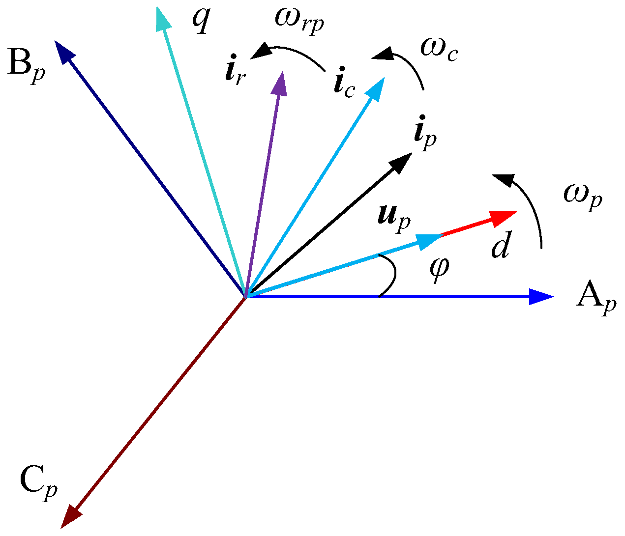
Using a grid voltage orientation strategy, the PW voltage vector is oriented with the d-axis. Then, according to (3)–(8), the vector diagram of a BDFG in a PW synchronous speed rotating coordinate system can be depicted as follows [29].
In Figure 2, the expression of the vector in the dq-axis coordinate system is F = fd + jfq, where F can represent any vector, and φ is the grid voltage phase.
For a BDFG in grid-connected operation, an instantaneous symmetrical drop in the grid voltage at the grid connection point of the wind farm is equivalent to the sudden addition of a reverse voltage source at the connection point, which inevitably leads to severe oscillations and overshoot in the PW, CW, and RW currents and electromagnetic torque. The worst case is that the grid voltage suddenly drops to 0 V, which is equivalent to a PW short circuit fault occurrence.
If the winding currents after the grid voltage fault must be solved, the steady state current before the fault and the transient current after the fault need to be calculated according to the superposition principle.
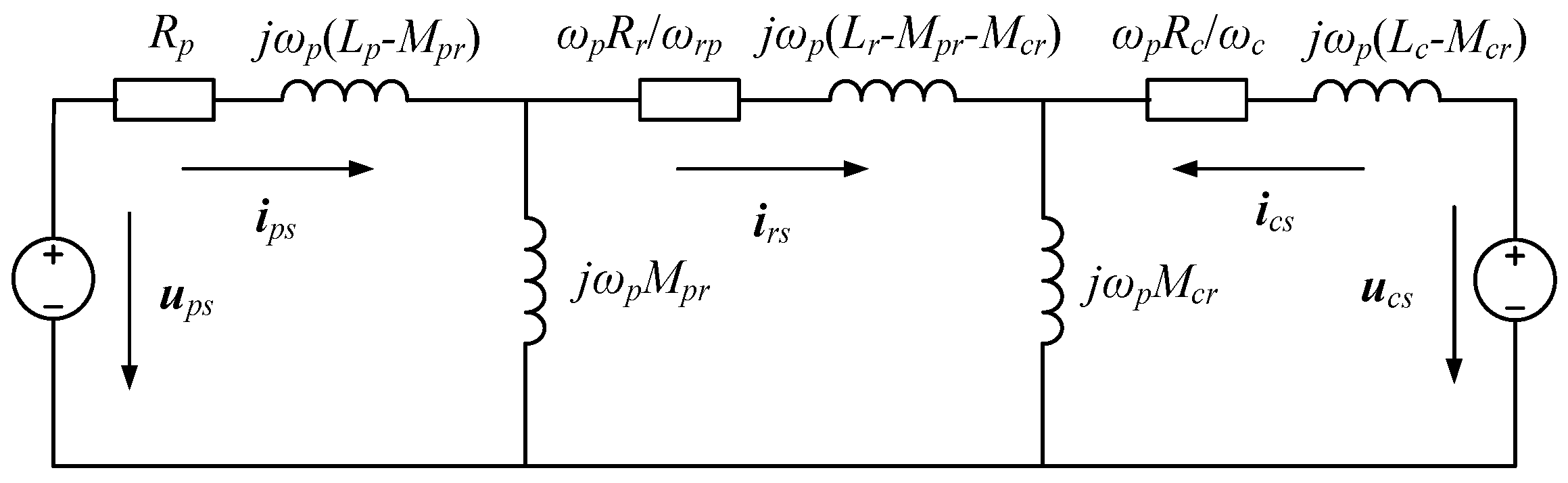
When the BDFG is in grid connection and stable operation, the differential terms in (3)–(8) are 0 and the steady-state equations are obtained. The steady-state equivalent circuit is shown in Figure 3.
The analytical expressions of the PW, CW, and RW currents of the BDFG in steady-state operation are obtained as follows:
i p s = u p s Z p s 1 + u c s Z p s 2 i c s = u p s Z c s 1 + u c s Z c s 2 i r s = u p s Z r s 1 + u c s Z r s 2
In (11), ups, ucs, ips, ics, and irs represent the steady-state voltages and currents of the PW, CW, and RW. The expressions of the steady-state impedances Zps1, Zps2, Zcs1, Zcs2, Zrs1, and Zrs2 are shown in Appendix A. To study the natural characteristics of generators under grid voltage drops, the following assumptions must be made: (1) there is no sudden change in the rotor speed before and after grid voltage drops; (2) the CW side voltage does not change before and after voltage drops.
The dynamic equivalent circuit of the BDFG in the case of an instantaneous drop in the grid voltage is shown in Figure 4.
In the case of an instantaneous symmetrical drop in the grid voltage, in (3)–(8), up = upf is a sudden reverse grid voltage, and upf = −kups, where k is the voltage drop degree coefficient of the PW. When k = 1, a reverse voltage with the same amplitude as the original grid voltage is suddenly added at the parallel node, that is, the grid voltage instantaneously drops to 0 V. Since the CW voltage is assumed to be constant, according to Thevenin’s theorem, when analyzing the impact of grid voltage fault, the CW voltage is 0 V, such that uc = ucf = 0. Then, ipf, icf, and irf represent the PW, CW, and RW currents generated by the grid fault. Via Laplace transformation and its inverse transformation, the solutions of the grid fault currents ipf, icf, and irf are as follows:
i p f = u p f Z p f 0 + u p f Z p f 1 e t T p e j ω p t + u p f Z p f 2 e t T c e j ω c t + u p f Z p f 3 e t T r e j ω r p t i c f = u p f Z c f 0 + u p f Z c f 1 e t T p e j ω p t + u p f Z c f 2 e t T c e j ω c t + u p f Z c f 3 e t T r e j ω r p t i r f = u p f Z r f 0 + u p f Z r f 1 e t T p e j ω p t + u p f Z r f 2 e t T c e j ω c t + u p f Z r f 3 e t T r e j ω r p t
In (12), Zpf0 is the impedance of the direct current (DC) steady-state component of the PW fault current. Zpf1, Zpf2, and Zpf3 are the impedances of the attenuated fundamental frequency, CW frequency, and RW frequency components of the PW fault current. The attenuated component of the fault current indicates that the flux linkage of the PW, CW, and RW does not suddenly change due to the principle of flux linkage conservation, so an oscillating current with an attenuation trend is generated in the PW circuit via these flux linkages. As Zcf0, Zcf1, Zcf2, and Zcf3 are the relevant impedances of the CW fault current, and Zrf0, Zrf1, Zrf2, and Zrf3 are the relevant impedances of the RW fault current, the meanings of these parameters can be analogized. The detailed expressions of these impedances are shown in Appendix A. The transient impedances are related to the BDFG’s parameters.
Furthermore, Tp, Tc, and Tr are the attenuation time constants of the PW, CW, and RW The expressions are described in (13).
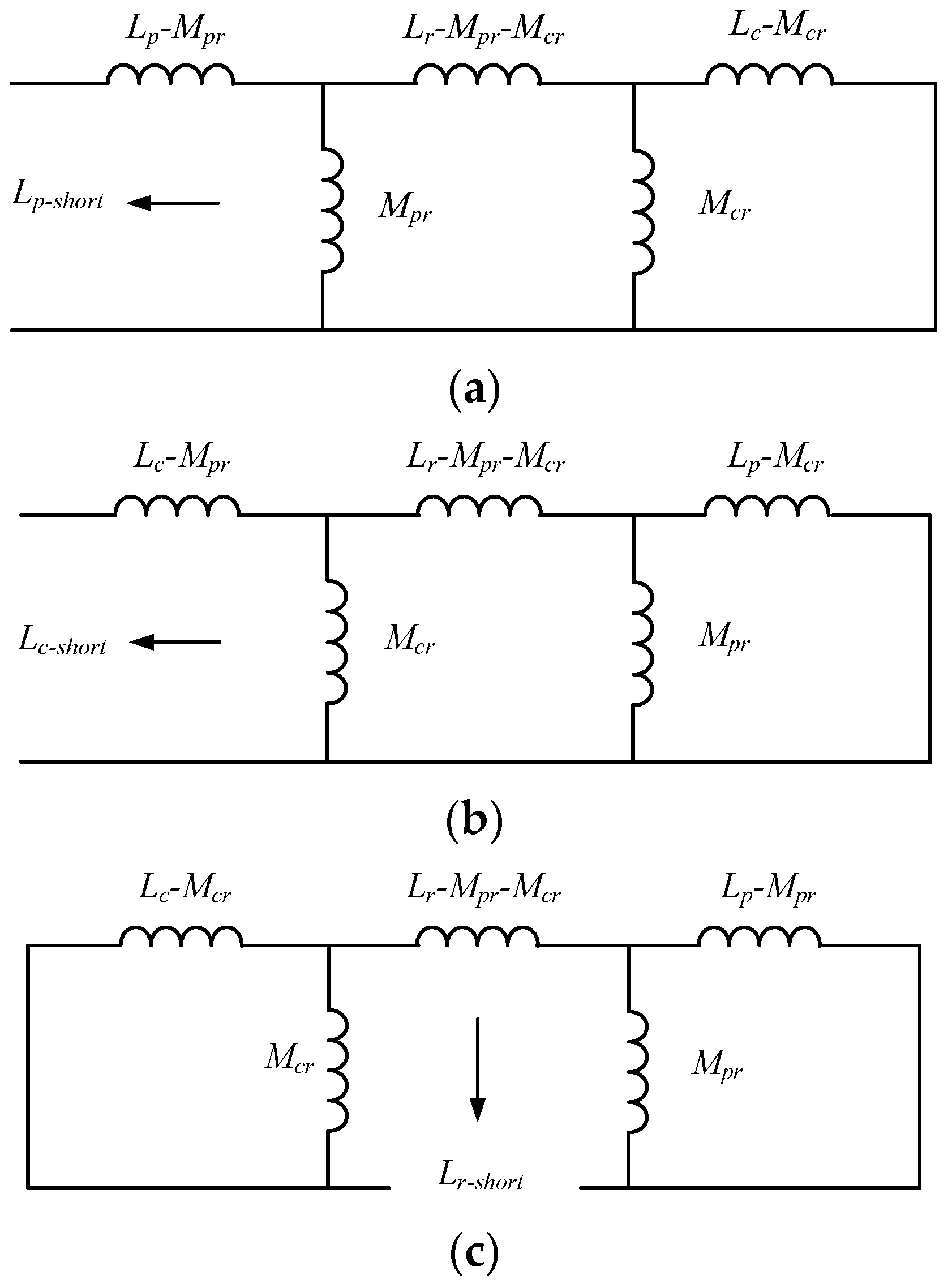
T p = L p L c L r     L p M c r 2     L c M p r 2 ( L c L r     M c r 2 ) 1 R p = L p - s h o r t R p T c = L p L c L r     L p M c r 2     L c M p r 2 ( L p L r     M p r 2 ) 1 R c = L c - s h o r t R c T r = L p L c L r     L p M c r 2     L c M p r 2 L p L c 1 R r = L r - s h o r t R r
In (13), Lp-short, Lc-short, and Lr-short are the short inductances of the PW, CW, and RW. These short-circuit inductors consist of leakage inductance circuits and mutual inductance. The circuit diagrams are shown in Figure 5.
The transient impedances are related to the BDFG’s parameters. The attenuation coefficients of the PW, CW, and RW are determined for a manufactured BDFG.
According to the superposition principle, the expressions of the PW, CW, and RW currents after the grid voltage fault occurs are the linear superpositions of the steady-state component and the dynamic component.
i p = u c s Z p s 2 + u p f Z p f 1 e t T p e j ω p t + u p f Z p f 2 e t T c e j ω c t + u p f Z p f 3 e t T r e j ω r p t i c = u c s Z c s 2 + u p f Z c f 1 e t T p e j ω p t + u p f Z c f 2 e t T c e j ω c t + u p f Z c f 3 e t T r e j ω r p t i r = u c s Z r s 2 + u p f Z r f 1 e t T p e j ω p t + u p f Z r f 2 e t T c e j ω c t + u p f Z r f 3 e t T r e j ω r p t
Thus far, the analytical expressions of the PW, CW, and RW currents of the BDFG have been solved in the PW synchronous vector space under an instantaneous symmetrical drop in the grid voltage. The analytical expressions in the three-phase static coordinate system can be obtained via a rotation transformation of the complex form. The simulations will be conducted in the following sections.
Based on (11), (12), and (14), the overshoot of the PW, CW, and RW currents is related to the CW voltage uc, the degree of grid voltage drops k, the phase of the grid voltage vector up (that is, φ in Figure 2), and the rotor speed ωr. The convergence speed is related to the parameters of the BDFG. The grid voltage drops inevitably, causing a sudden increase and oscillations in the PW, CW, and RW currents. In the actual brushless doubly fed wind power generation system, the drop degree and phase of the grid voltage cannot be controlled, and the rotor speed will not suddenly change due to the inertia of the generator. Only the CW voltage of the BDFG can be changed via certain control methods to reduce overshoot and accelerate convergence, and this function can be realized via optimal control.

4. The Optimal Control Strategy

According to modern control theory, combined with the characteristics of the BDFG model during grid voltage drop faults, its input is the voltage and phase of the CW, the initial conditions are determined, the fault duration is determined, and the terminal is free. If the objective function is set as the finite-time integral value of the square of the electromagnetic torque Te at this time, making it achieve the minimum value, it could suppress the oscillation of the electromagnetic torque. The model can be established via the Pontryagin minimum principle in optimal control, and the optimal CW voltage command value can be directly solved.
The special structure of the BDFG’s rotor is a self-closing short circuit with no wiring leads. The RW only serves to transfer a magnetic field and energy and hardly provides active power. Moreover, the RW current is generally not considered in the control loop. Therefore, ignoring the RW’s resistance and utilizing the 0 V rotor voltage condition, (3)–(10) are simplified into a reduced-order model of the BDFG described in (15)–(17). Motor conventions are used on both the power side and the control side.
u p = R p i p + ( p + j ω p ) ( L s p i p + M p c i c )
u c = R c i c + ( p j ω c ) ( L s c i c + M p c i p )
T e = ( p p + p c ) M p c Im ( i p i c )
The relationship between the parameters in (15)–(17) and the parameters in (3)–(10) is
L s p = L p M p r 2 L r   L s c = L c M c r 2 L r M p c = M p r M c r L r
According to mathematical models (15)–(17), under the condition of the PW voltage orientation, taking the dq-axis components of the CW current as the state variable and the dq-axis components of the CW and PW voltages as the input, the state equation is obtained, as shown in (19):
p i c d i c q = λ m R p M p c 2 L s p R c L s p ( ω p ω r e ) M p c 2 + ω c L s p L s c ( ω p ω r e ) M p c 2 ω c L s p L s c R p M p c 2 L s p R c L s p i c d i c q + λ m L s p u c d u c q λ m M p c u p d 0 + λ m ω r e M p c ψ p q R p M p c ψ p q L s p
where ωre is the equivalent electrical angular velocity of the BDFG:
ω r e = ω r ( p p + p c )
and the expression of λm is
λ m = 1 L s p L s c M p c 2
Under steady-state conditions, the relationship between the d-axis component of the PW voltage upd and the q-axis component of the PW flux linkage ψpq is
u p d = ω p ψ p q
Since the parameters of the generator system are determined after the instantaneous symmetrical drop in the grid voltage, the generator system described in (19) is considered scleronomous. Because upd is a constant, ucd and ucq are free variables. Therefore, when discussing optimal control, the input term of upd can be ignored. The state space Equation (19) is reconstructed as follows:
d x d t = A x + B u = f [ x , u , t ]
x = i c d i c q T u = u c d u c q T
A = λ m R p M p c 2 L s p R c L s p ( ω p ω r e ) M p c 2 + ω c L s p L s c ( ω p ω r e ) M p c 2 ω c L s p L s c R p M p c 2 L s p R c L s p
The mathematical model shown in (23) is the research object of optimal control. After the model is established, the initial condition, constraints condition, and performance function are determined. Then, the optimal control input must be solved.
According to the optimal control theory, the objective function is the finite-time integral value of the square of the electromagnetic torque Te. Then, the minimum value principle is used.
The starting condition is
x ( t 0 ) = x 0 = i c d 0 i c q 0 T
The control constraints condition is
U u U , U = [ u c m a x u c m a x ] T
where ucmax is the maximum allowable CW voltage amplitude. Both ucd and ucq cannot exceed the maximum value of the CW voltage amplitude. This is because the CW voltage is limited by the capacity of power electronic devices, so there is a maximum value for ucd and ucq.
The terminal time tf is determined, and the state x(tf) is free:
λ ( t f ) = 0
The performance function is
J = t 0 t f L [ x ( t ) , u ( t ) , t ] d t
The expression of L is
L [ x ( t ) , u ( t ) , t ] = T e 2
According to the approximate expression of Te described in (17), the square of the electromagnetic torque is
T e 2 = 3 u p d M p c 2 ω p L s p ( p p + p c ) 2 i c d i c q 1 0 0 0 i c d i c q = x T Q x
The Hamiltonian function is taken as
H = L [ x ( t ) , u ( t ) , t ] + λ T f [ x , u , t ]
The necessary conditions for achieving optimal control are the optimal control u*, the optimal trajectory x*, and the optimal covariance vector λ* meeting the state Equation (33) and the costate Equation (34):
x · = H λ = A x + B u
λ · = H x = 2 Q x A λ
The system of equations could be theoretically solved with the simultaneous Equations (26), (28), (33), and (34). According to the characteristics of the matrices L and Q, only the d-axis component icd of the CW current is included, and it is independent of the q-axis component icq. Then, the initial value of ucq can be used, and only the optimal solution of ucd needs to be solved:
u c d - o p t = ( R p M p c 2 L s p 2 + R c ) i c d 0 1 e ( λ 1 λ 2 ) t f [ e λ 2 t e ( λ 1 λ 2 ) t f e λ 1 t ] [ 1 L s p ( ω p ω r e ) M p c 2 + ω c L s c ] i c q 0 u c q - o p t = [ 1 L s p ( ω p ω r e ) M p c 2 + ω c L s c ] i c d 0 ( R p M p c 2 L s p 2 + R c ) i c q 0
In (35), ucd-opt and ucq-opt are the optimal CW voltage reference values, and λ1 and λ2 are the characteristic roots of the system matrix A, expressed as
λ 1 , 2 = R p M p c 2 L s p R c L s p ± j ( R p M p c 2 L s p + R c L s p ) 2 4 ω c 2 ( M p c 2 L s p L s c ) 2
Considering that the exponential function is difficult to express in the algorithm, the instruction values of ucd-opt and ucq-opt in the program are given equivalent sectional fixed values, which can restrain the oscillations of the electromagnetic torque oscillation.
The switching logic between conventional PI control and optimal control is shown in Figure 6, where the superscript * represents the instruction value.
The optimal control strategy is only enabled during the instantaneous voltage drop period in the power grid, and the optimal command values ucd-opt and ucq-opt of the optimal CW are directly given at this time. The working states before the drop and after the power grid fault are both closed-loop dual PI control strategies.

5. Experimental Results

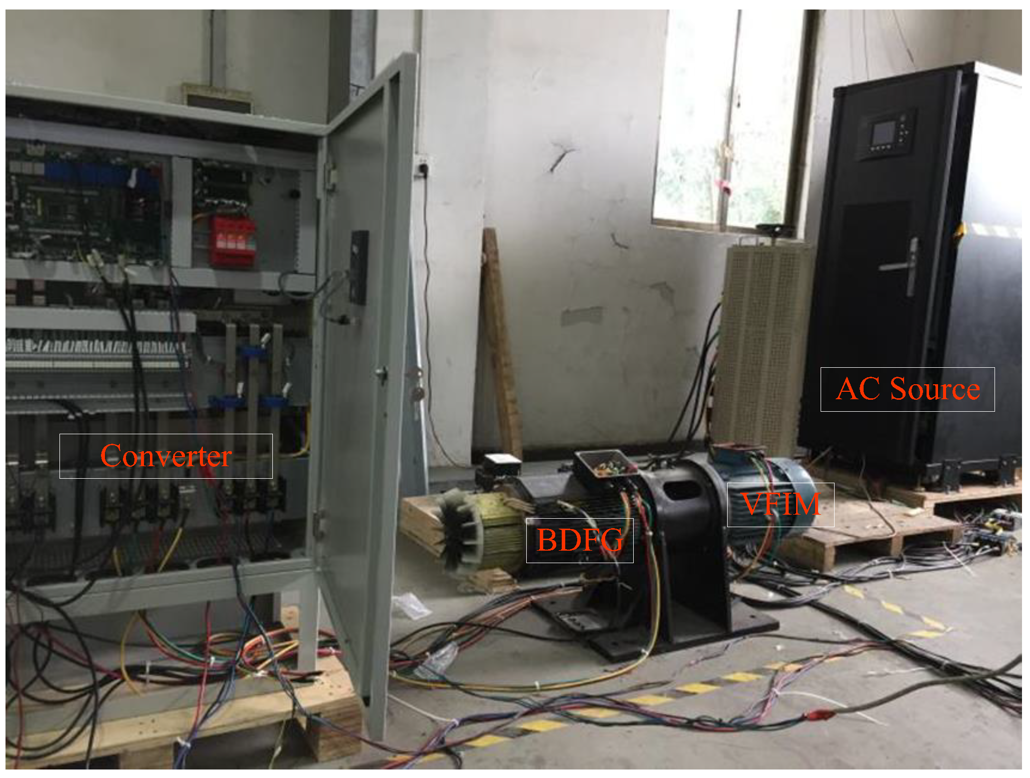
Figure 7 shows a brushless doubly fed wind power generation system platform. The prime mover is a variable-frequency induction motor (VFIM), which simulates the wind turbine. The speed of the motor ωr, that is, the speed of the brushless doubly fed generator, is controlled with a general-purpose inverter. The system is equipped with an AC source, which is a grid simulator that can generate grid voltage drops.
The parameters of the BDFG in Figure 7 are shown in Table 1.
The algorithm period of the system is 160 us, the sampling period is 160 us, and the IGBT switching period is 6.25 kHz. The root mean square of the grid voltage phase–phase is 380 V, and the frequency is 50 Hz. The rotor speed is regulated at 900 rpm. The active power is 4 kW, and the reactive power is 0 kvar.
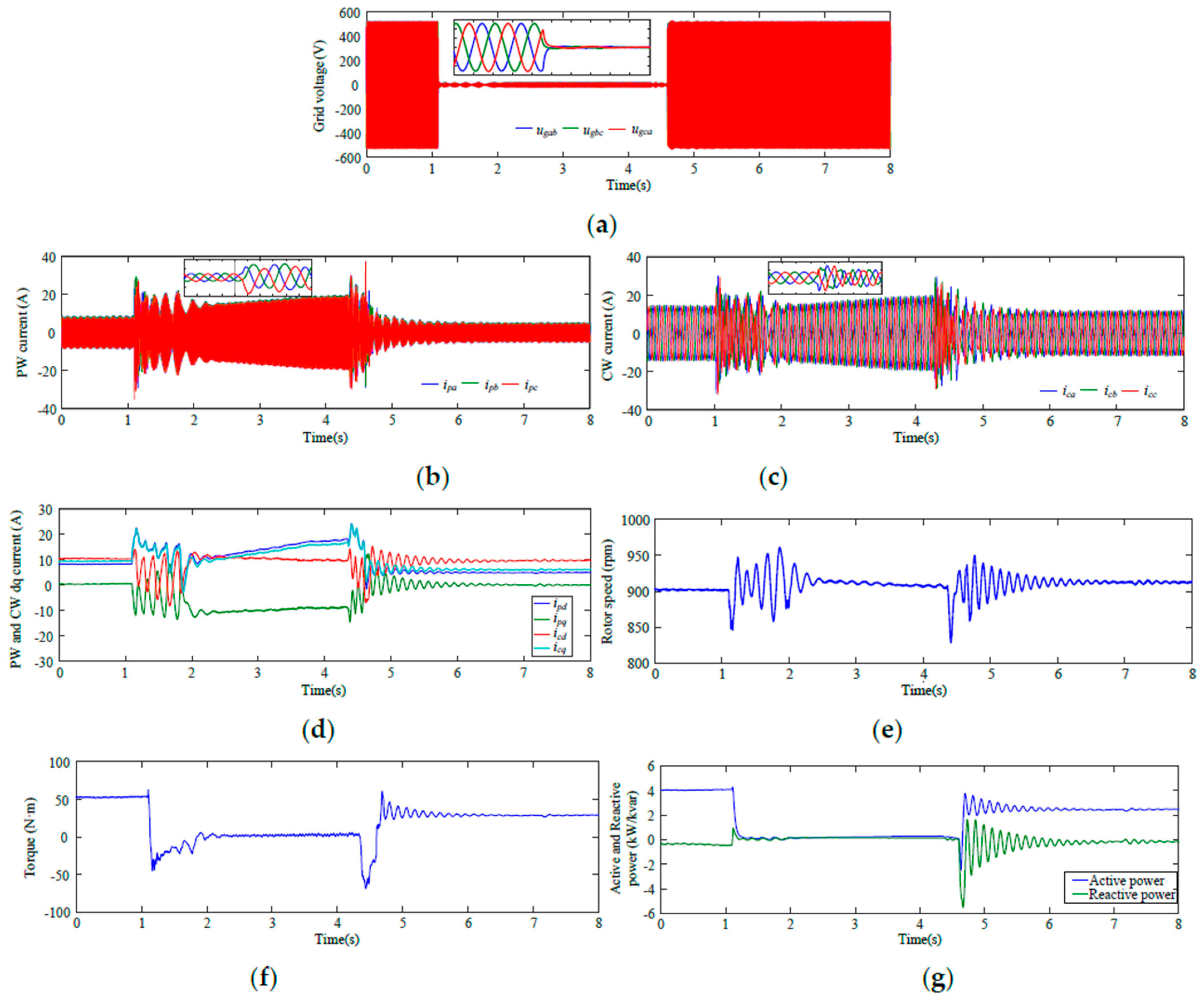
First, the system waveform under traditional PI control is observed and analyzed. The overshoot and oscillations in the physical quantities of the generator are obvious, and the duration reaches 1.3 s. As seen in Figure 8b, the change in the PW current is very obvious, where its peak value increases from 8.5 A to 32 A, an increase of approximately 3.7 times. Figure 8c shows that the CW current amplitude is 15 A before the grid voltage drops and suddenly rises to 32 A, increasing to 2.1 times the rated value, which is quite bad for a converter. At the same time, Figure 8d shows that icq is synchronous with ipd, but icd changes inversely with ipq, such that ipd = icd and ipq = −icq. There are severe oscillations in the four dq components. Figure 8e shows that the maximum rotor speed ωr reaches 1000 rpm, and the minimum speed is 820 rpm. Figure 8f shows a large fluctuation in the torque Te, which changes from −50 N·m to 50 N·m. Figure 8g shows a fluctuation in the PW’s active and reactive power.
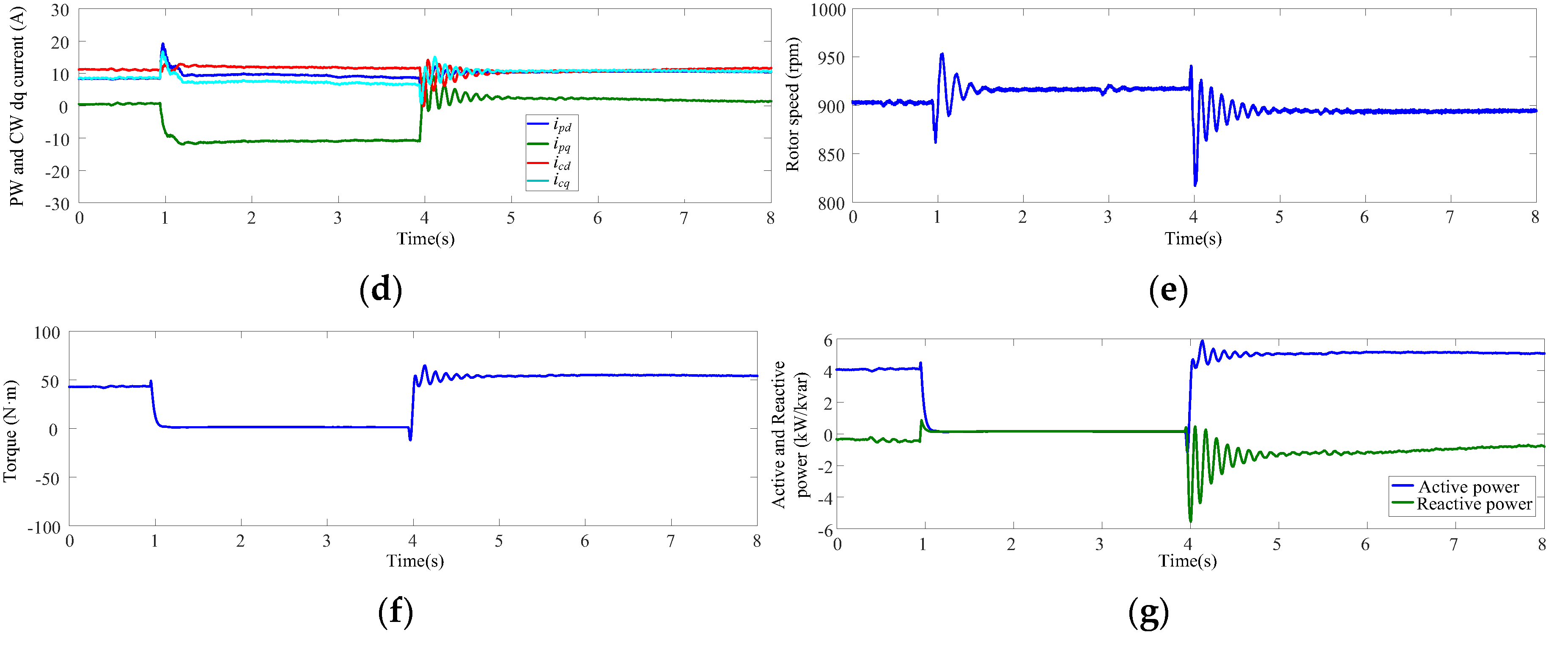
The system waveform under the optimal control strategy is shown in Figure 9. As seen in Figure 9b, the peak value of the PW current increases to 25.5 A from 8.5 A and stabilizes after three cycles at 15 A. Figure 9c shows that the oscillations in the CW current cease after a period, and the stable value is the same as the rated value. Its maximum amplitude is only 1.7 times its rated value of 25 A. That is, the current of the converter does not exceed two times the rated value, which is within the bearing range of the IGBT. Figure 9d shows that ipd increases to 16 A from 8.5 A, and icq increases to 12 A from 7.5 A. However, they quickly stabilize. Then, ipq drops to −9 A from 0 A but can be quickly stabilized. Furthermore, icd changes very little and stays near 12.5 A. Finally, Figure 9e demonstrates that the maximum rotor speed ωr reaches 960 rpm, and the minimum speed is 870 rpm. Figure 9f shows a minor fluctuation in the torque Te. Figure 9g shows that the fluctuation in the PW’s active and reactive power is small.
Comparing Figure 9 and Figure 10, it can be observed that the optimal control and flux linkage tracking control are comparable. The dynamic performance indicators of the PI control, flux linkage tracking, and optimal control are shown in Table 2. The numerical values of the PI and optimal control methods are on the left and right, respectively.

6. Conclusions

In this paper, the transient characteristics of a BDFG under grid faults were revealed by solving the analytical expression of the BDFG’s stator and rotor winding currents during a transient voltage drop in the power grid. It was found that the system’s overshoot was related to the CW voltage. Furthermore, an optimal control method was proposed to suppress the oscillation in the generator’s electromagnetic torque during faults. This strategy can reduce the peak values of the PW, CW, and RW currents and shorten the convergence time.
The experimental results show that the overshoot of the physical quantities of the generator under flux linkage tracking control and optimal control are significantly smaller than those under the traditional PI control strategy when dealing with voltage drops. Moreover, the oscillation duration is shortened, and the anti-disturbance ability of the whole control system is enhanced. The performance indicators such as the transient response, the current and torque overshoot, and the convergence time of advanced algorithms such as flux linkage tracking and optimal control are significantly better than those of traditional PI control. The optimal control and flux linkage tracking control are comparable. Therefore, the effectiveness and practicability of the optimal strategy have been verified.

Author Contributions

J.X. designed the principles of the overall work, proposed the control strategies, and prepared the initial draft of this paper. P.N. implemented software programming, proposed some technical comments, and edited the final draft of this paper. All authors have read and agreed to the published version of the manuscript.

Funding

This research received no external funding.

Data Availability Statement

Data is contained within the article.

Conflicts of Interest

The authors declare no conflicts of interest.

Appendix A

Z m 3 = j ω p ω c ω r p ( L p L c L r L p M c r 2 L c M p r 2 ) + j ω p L p R c R r j ω c L c R p R r + j ω r p L r R p R c + R p R c R r + ω p ω c L p L c R r ω p ω r p ( L p L r M p r 2 ) R c + ω c ω r p ( L c L r M c r 2 ) R p
Z p s 1 = Z m 3 R r R c j ω c L c R r + j ω r p L r R c + ( L p L r M c r 2 ) ω c ω r p
Z p s 2 = Z m 3 M p r M c r ω p ω r p , Z c s 1 = Z m 3 M p r M c r ω r p ω c
Z c s 2 = Z m 3 R p R r + j ω p L p R r + j ω r p L r R p ( L p L r M p r 2 ) ω p ω r p
Z r s 1 = Z m 3 j ω r p M p r ( R c j ω c L c ) , Z r s 2 = Z m 3 j ω r p M c r ( R p + j ω p L p )
L m 3 = L p L c L r L p M c r 2 L c M p r 2 λ 1 = 1 T p j ω p , λ 2 = 1 T c + j ω c , λ 3 = 1 T r j ω r p
Z p f 0 = L m 3 λ 1 λ 2 λ 3 R r R c     j ω c L c R r   +   j ω r p L r R c   +   ( L p L r     M c r 2 ) ω c ω r p Z p f 1 = L m 3 ( λ 3     λ 1 ) ( λ 1     λ 2 ) ( L c L r     M c r 2 ) ( λ 1     λ 2     λ 3 )     λ 2 λ 3 L m 3 Z p f 0 Z p f 2 = L m 3 ( λ 1     λ 2 ) ( λ 2     λ 3 ) ( L c L r     M c r 2 ) ( λ 2     λ 1     λ 3 )     λ 1 λ 3 L m 3 Z p f 0 Z p f 3 = L m 3 ( λ 2     λ 3 ) ( λ 3     λ 1 ) ( L c L r     M c r 2 ) ( λ 3     λ 1     λ 2 )     λ 1 λ 2 L m 3 Z p f 0
Z c f 0 = L m 3 λ 1 λ 2 λ 3 M p r M c r ω r p ω c Z c f 1 = L m 3 ( λ 3     λ 1 ) ( λ 1     λ 2 ) λ 1 M p r M c r     M p r M c r ( j ω r p     j ω c )     λ 2 λ 3 L m 3 Z c f 0 Z c f 2 = L m 3 ( λ 1     λ 2 ) ( λ 2     λ 3 ) λ 2 M p r M c r     M p r M c r ( j ω r p     j ω c )     λ 1 λ 3 L m 3 Z c f 0 Z c f 3 = L m 3 ( λ 2     λ 3 ) ( λ 3     λ 1 ) λ 3 M p r M c r     M p r M c r ( j ω r p     j ω c )     λ 1 λ 2 L m 3 Z c f 0
Z r f 0 = L m 3 λ 1 λ 2 λ 3 j ω r p M p r ( R c     j ω c L c ) Z r f 1 = L m 3 ( λ 3     λ 1 ) ( λ 1     λ 2 ) λ 1 L c M p r   +   M p r ( R c   +   j ω r p L c     j ω c L c )     λ 2 λ 3 L m 3 Z r f 0 Z r f 2 = L m 3 ( λ 1     λ 2 ) ( λ 2     λ 3 ) λ 2 L c M p r   +   M p r ( R c   +   j ω r p L c     j ω c L c )     λ 1 λ 3 L m 3 Z r f 0 Z r f 3 = L m 3 ( λ 2     λ 3 ) ( λ 3     λ 1 ) λ 3 L c M p r   +   M p r ( R c   +   j ω r p L c     j ω c L c )     λ 1 λ 2 L m 3 Z r f 0

References

  1. Xiong, F.; Wang, X. Design of a low-harmonic-content wound rotor for the brushless doubly fed generator. IEEE Trans. Energy Convers. 2014, 29, 158–168. [Google Scholar] [CrossRef]
  2. Kong, M.; Wang, X.; Li, Z. Asynchronous operation characteristics and soft-starting method for the brushless doubly-fed motor. IET Electr. Power Appl. 2017, 11, 1276–1277. [Google Scholar] [CrossRef]
  3. Zhu, L.; Zhang, F.; Jin, S.; Ademi, S.; Su, X.; Cao, W. Optimized Power Error Comparison Strategy for Direct Power Control of the Open-Winding Brushless Doubly Fed Wind Power Generator. IEEE Trans. Sustain. Energy 2019, 10, 2005–2006. [Google Scholar] [CrossRef]
  4. Abdi, S.; Abdi, E.; McMahon, R. A New Iron Loss Model for Brushless Doubly-Fed Machines With Hysteresis and Field Rotational Losses. IEEE Trans. Energy Convers. 2021, 36, 3221–3229. [Google Scholar] [CrossRef]
  5. Kan, C.; Zheng, J.; Wang, X.; Wang, Q. Design and Starting Performance Study of a Soft-Start Brushless Doubly Fed Machine. IEEE Trans. Energy Convers. 2022, 37, 97–106. [Google Scholar] [CrossRef]
  6. Chen, X.; Wang, X.; Kong, M.; Li, Z. Design of a Medium-Voltage High-Power Brushless Doubly Fed Motor With a Low-Voltage Fractional Convertor for the Circulation Pump Adjustable Speed Drive. IEEE Trans. Ind. Electron. 2022, 69, 7720–7731. [Google Scholar] [CrossRef]
  7. Sadeghi, R.; Madani, S.M.; Ataei, M. A New Smooth Synchronization of Brushless Doubly-Fed Induction Generator by Applying a Proposed Machine Model. IEEE Trans. Sustain. Energy 2018, 9, 371–379. [Google Scholar] [CrossRef]
  8. Wang, X.; Lin, H. DC-link current estimation for load-side converter of brushless doubly-fed generator in the current feed-forward control. IET Power Electron. 2016, 9, 1703–1704. [Google Scholar] [CrossRef]
  9. Yan, X.; Cheng, M. A Robustness-Improved Control Method Based on ST-SMC for Cascaded Brushless Doubly Fed Induction Generato. IEEE Trans. Ind. Electron. 2021, 68, 7061–7070. [Google Scholar] [CrossRef]
  10. Xu, L.; Cheng, M.; Wei, X.; Yan, X.; Zeng, Y. Dual Synchronous Rotating Frame Current Control of Brushless Doubly Fed Induction Generator Under Unbalanced Network. IEEE Trans. Power Electron. 2021, 36, 6712–6723. [Google Scholar] [CrossRef]
  11. Ge, J.; Xu, W.; Liu, Y.; Xiong, F. Novel Equivalent Circuit Model Applicable to All Operation Modes for Brushless Doubly Fed Induction Machines. IEEE Trans. Ind. Electron. 2022, 69, 12540–12549. [Google Scholar] [CrossRef]
  12. Ruiz-Cruz, R.; Sanchez, E.N.; Loukianov, A.G.; Ruz-Hernandez, J.A. Real-Time Neural Inverse Optimal Control for a Wind Generator. IEEE Trans. Sustain. Energy 2019, 10, 1172–1182. [Google Scholar] [CrossRef]
  13. Zeng, Y.; Cheng, M.; Wei, X.; Zhang, G. Grid-Connected and Standalone Control for Dual-Stator Brushless Doubly Fed Induction Generator. IEEE Trans. Ind. Electron. 2021, 68, 9196–9205. [Google Scholar] [CrossRef]
  14. Gowaid, I.A.; Abdel-Khalik, A.S.; Massoud, A.M.; Ahmed, S. Ride-Through Capability of Grid-Connected Brushless Cascade DFIG Wind Turbines in Faulty Grid Conditions—A Comparative Study. IEEE Trans. Sustain. Energy 2013, 4, 1002–1013. [Google Scholar] [CrossRef]
  15. Shao, S.; Abdi, E.; McMahon, R. Dynamic Analysis of the Brushless Doubly-Fed Induction Generator during Symmetrical Three-Phase Voltage Dips. In Proceedings of the 2009 International Conference on Power Electronics and Drive Systems (PEDS), Taipei, China, 2–5 November 2009. [Google Scholar]
  16. Sadeghi, R.; Madani, S.M.; Lipo, T.A.; Kashkooliet, M.R.A.; Ataei, M.; Ademi, S. Voltage-Dip Analysis of Brushless Doubly Fed Induction Generator Using Reduced T-Model. IEEE Trans. Ind. Electron. 2019, 66, 7510–7512. [Google Scholar] [CrossRef]
  17. Tohidi, S.; Hashem, O.; Zolghadri, M.R.; Shao, S.; Tavner, P. Analysis and Enhancement of Low-Voltage Ride-Through Capability of Brushless Doubly Fed Induction Generator. IEEE Trans. Ind. Electron. 2013, 60, 1149–1150. [Google Scholar] [CrossRef]
  18. Abdi, E.; McMahon, R.; Malliband, P. Performance analysis and testing of a 250 kW medium-speed brushless doubly-fed induction generator. IET Renew. Power Gener. 2013, 7, 636–637. [Google Scholar] [CrossRef]
  19. Long, T.; Shao, S.; Malliband, P.; Abdi, E.; McMahon, R. Crowbarless Fault Ride-Through of the Brushless Doubly Fed Induction Generator in a Wind Turbine Under Symmetrical Voltage Dips. IEEE Trans. Ind. Electron. 2013, 60, 2836–2837. [Google Scholar] [CrossRef]
  20. Betz, R.E. Comparison of Rotor Side Converter Protection for DFIGs and Brushless Doubly Fed Reluctance Machines under Fault Conditions. In Proceedings of the 2021 23rd European Conference on Power Electronics and Applications (EPE’21 ECCE Europe), Ghent, Belgium, 6–10 September 2021; pp. 1–10. [Google Scholar]
  21. Wang, Z.; Xu, H.; Li, Z. Small Signal Impedance Modeling and Stability Analysis of BDFIG Tied into Weak Power Grid. In Proceedings of the 2021 IEEE 4th International Electrical and Energy Conference (CIEEC), Wuhan, China, 28–30 May 2021; pp. 1–6. [Google Scholar]
  22. Wang, S.; Shang, L. Fault Ride Through Strategy of Virtual-Synchronous-Controlled DFIG Based Wind Turbines Under Symmetrical Grid Faults. IEEE Trans. Energy Convers. 2020, 35, 1360–1371. [Google Scholar] [CrossRef]
  23. Huang, J.; Li, S. Analytical expression for LVRT of BDFIG with enhanced current control to CW and reactive power support from GSC. Elsevier Electr. Power Energy Syst. 2018, 98, 243–255. [Google Scholar] [CrossRef]
  24. Lu, M.; Chen, Y.; Zhang, D.; Su, J.; Kang, Y. Virtual Synchronous Control Based on Control Winding Orientation for Brushless Doubly Fed Induction Generator (BDFIG) Wind Turbines Under Symmetrical Grid Faults. Energies 2019, 12, 319. [Google Scholar] [CrossRef]
  25. Zhang, A.; Chen, Z.; Gao, R.; Wang, J.; Ma, Z.; Wang, S.; Wang, Y. Crowbarless Symmetrical Low-Voltage Ride Through Based on Flux Linkage Tracking For Brushless Doubly Fed Induction Generators. IEEE Trans. Ind. Electron. 2019, 67, 7606–7616. [Google Scholar] [CrossRef]
  26. Sun, L.; Chen, Y.; Peng, L.; Kang, Y. Numerical-based frequency domain controller design for stand-alone brushless doubly fed induction generator power system. IET Power Electron. 2017, 10, 588–598. [Google Scholar] [CrossRef]
  27. Shipurkar, U.; Strous, T.D.; Polinder, H.; Ferreira, J.A.; Veltman, A. Achieving Sensorless Control for the Brushless Doubly Fed Induction Machine. IEEE Trans. Energy Convers. 2017, 32, 1612–1613. [Google Scholar] [CrossRef]
  28. Liu, Y.; Xu, W.; Zhu, J.; Blaabjerg, F. Sensorless Control of Standalone Brushless Doubly Fed Induction Generator Feeding Unbalanced Loads in a Ship Shaft Power Generation System. IEEE Trans. Ind. Electron. 2019, 66, 741–742. [Google Scholar] [CrossRef]
  29. Ouyang, J.; Tang, T.; Diao, Y.; Li, M.; Yao, J. Control method of doubly fed wind turbine for wind speed variation based on dynamic constraints of reactive power. IET Renew. Power Gener. 2018, 12, 973–974. [Google Scholar] [CrossRef]
Figure 1. Equivalent schematic diagram of BDFG.
Energies 17 00235 g001
Figure 2. Vector diagram of the rotating coordinate system.
Energies 17 00235 g002
Figure 3. Steady-state equivalent circuit diagram of BDFG.
Energies 17 00235 g003
Figure 4. Grid fault equivalent circuit diagram of BDFG.
Energies 17 00235 g004
Figure 5. Short inductances of PW, CW, and RW. (a) PW short inductance, (b) CW short inductance, and (c) RW short inductance.
Energies 17 00235 g005
Figure 6. Optimal control structure of the BDFG.
Energies 17 00235 g006
Figure 7. Experimental platform of a brushless doubly fed power generation system.
Energies 17 00235 g007
Figure 8. (a) Grid voltage, (b) PW current, (c) CW three-phase current, (d) PW and CW current dq components, (e) rotor speed, (f) electromagnetic torque, and (g) active and reactive power under PI control.
Energies 17 00235 g008
Figure 9. (a) Grid voltage, (b) PW current, (c) CW three-phase current, (d) PW and CW current dq components, (e) rotor speed, (f) electromagnetic torque, and (g) active and reactive power under optimum control.
Energies 17 00235 g009aEnergies 17 00235 g009b
Figure 10. (a) Grid voltage, (b) PW current, (c) CW current, (d) PW and CW current dq components, (e) rotor speed, (f) electromagnetic torque, and (g) active and reactive power under flux linkage tracking.
Energies 17 00235 g010
Table 1. Prototype machine parameters for experiments.
ParameterValueParameterValueParameterValueParameterValue
Machine rating4 kWPW rated current6 ALp0.6659 HMcr0.1841 H
PW/CW pole pairs1/3CW rated current10 ALc0.1898 HRp2.5 Ω
PW rated voltage380 V (50 Hz)Operating speed600~1200 r/mLr0.8442 HRc2.3 Ω
CW rated voltage230 V (30 Hz)Rated torque80 N·mMpr0.6547 HRr2.9 Ω
Table 2. Quantity comparison between PI control, flux linkage tracking, and optimal control.
VariableExtremumExtremum TimeRegulating TimeOvershoot
ipd−15 A/20 A/15.5 A0.2 s/0.02 s/0.02 s1.3 s/0.9 s/0.8 s275%/100%/100%
ipq−24 A/−12 A/−12 A0.05 s/0.03 s/0.02 s1.3 s/0.9 s/0.8 s189%/112%/112%
icd25 A/13 A/16 A0.1 s/0.03 s/0.02 s1.3 s/0.9 s/0.8 s150%/33%/33%
icq−15 A/19 A/18 A0.05 s/0.03 s/0.02 s1.3 s/0.9 s/0.8 s275%/100%/100%
Te70 N·m/70 N·m/70 N·m0.05 s/0.03 s/0.02 s1.3 s/0.9 s/0.8 s600%/248%/250%
nr1000 rpm/958 rm/960 rm0.1 s/0.03 s/0.02 s1.3 s/0.9 s/0.8 s8.7%/4.8%/4.4%
Disclaimer/Publisher’s Note: The statements, opinions and data contained in all publications are solely those of the individual author(s) and contributor(s) and not of MDPI and/or the editor(s). MDPI and/or the editor(s) disclaim responsibility for any injury to people or property resulting from any ideas, methods, instructions or products referred to in the content.

