Abstract
In a previous work, a solar chimney power plant integrated with a solid sorption cooling system for power and cold cogeneration was developed. This prior work showed that reusing the heat released from the adsorption bed enhances the system’s utilization of solar energy and increases the turbine’s output power. In the present paper, a subsequent modification to the arrangement and operation of the preceding system is introduced. The primary objective of the modification is to enhance performance and increase the plant’s capacity to effectively harness the available solar radiation. The method involves placing the condenser tubes at the solar collector entrance. Therefore, the airflow captures the condenser-released heat before it enters the collector. The modified configuration and operation of the system are discussed. A dynamic mathematical model is established to simulate the hybrid system’s operation and evaluate its parameters. The obtained results show that a 5.95% increase in output power can be achieved by recovering the heat of condensation. Furthermore, the modified system attains a 6% increase in solar-to-electricity conversion efficiency compared with the basic system. The findings suggest that the modified system, which recycles condenser heat, provides noticeable enhanced performance compared with the basic system.
1. Introduction
In recent years, there have been a significant rise in the worldwide population and increasing industrial development, leading to worrisome consequences for global energy demand and supply [1]. The limited availability of traditional fossil fuels, the potential threat they pose to life on Earth, and their detrimental impact on the environment necessitate more regulations and restrictions. The current energy framework demands advancements in the realm of clean and sustainable energy [2]. In contemporary times, green energy sources have assumed a pivotal role in promoting clean energy generation devoid of carbon emissions while also fostering environmentally friendly practices and ensuring sustainability in the environment [3]. In this context, a dependable, renewable, and emission-free clean energy source that can be found everywhere and is available around the year is solar radiation. Solar radiation can be transformed into electricity using several methods. Using solar chimney power plants is one way to turn solar energy into electricity [1]. Furthermore, it has been proven that solar energy can be converted into cold for cooling and refrigeration purposes [4]. For instance, in adsorption-based cooling and refrigeration systems, solar energy has been used to release refrigerant vapor from the adsorption bed [5].
The production of ice from the heat of the sun is no longer regarded as a magical or astonishing phenomenon in contemporary technology. It is well known that the energy from the sun has been harnessed for the purpose of powering chillers and freezers that rely on thermal energy for their operation. Heat-powered cold-generating systems encompass steam ejector units, absorption ice makers, and solid sorption cold-producing equipment. Sunlight-driven cooling technologies utilize the sun’s heat to run the cooling cycle by means of collection or focusing [6]. Vapor adsorption cooling and freezing systems have emerged as a highly appealing approach within the realm of heat-driven refrigeration systems. Currently, adsorption technology is widely acknowledged for its practicality, environmental friendliness, and energy efficiency in harnessing low-grade and ultra-low-grade heat [7] to attain various beneficial outcomes at the level of domestic as well as industrial applications [8].
It is noteworthy to point out that in contrast to the absorption-based and steam ejector cooling cycles, the adsorption-based cold-generating cycle has the advantage of using low-grade heating energy. For instance, the generation of coolant gas from the adsorption bed can be achieved by utilizing a heating source with a temperature of 50 °C, particularly when employing silica gel as an adsorption medium with water as the coolant fluid [9]. The aforementioned statement highlights the appeal of researching solar-powered adsorption-based cold-generating devices [10]. Within the realm of the scholarly literature, numerous investigations have been undertaken to explore, enhance, and modify these systems with experimental, theoretical, or combined approaches [11,12,13,14,15]. Furthermore, there are a considerable number of studies on the effective implementation of low-quality thermal energy sources other than solar energy. These investigations include the manipulation of geothermal energy [16] and industrial waste heat [17,18].
The adsorption cooling operating cycle bears resemblance to the vapor compression cooling cycle, albeit with a distinct variation in the operation of the compression operation. Instead of a mechanical compressor like in vapor compression systems, the adsorption bed in the adsorption refrigeration cycle works as a compressor that is powered by heat [3]. The adsorption bed comprises a solid adsorption medium and a coolant gas. Activated carbon, silica gel, and zeolite are frequently employed as adsorption materials [19]. Methanol, ammonia, and water are frequently employed as coolant fluids. Enhancing the adsorption uptake capability of the adsorbent substances is a crucial prerequisite for the efficient and cost-effective functioning of adsorption-based cooling technologies [12]. Many studies have been conducted on the practical application of vapor adsorption cold-producing technology. Examples of the previous research studies include ice makers [20,21,22], vaccine refrigerators [23,24], building heating and cooling applications [25,26,27,28], automotive air-conditioning applications [18,29], storage of food and agricultural products [30,31,32], and others.
The solar chimney power plant, also known as the solar updraft tower power plant, is a relatively simple and environmentally friendly approach to harnessing solar energy to produce electricity. The standalone solar updraft tower power plant comprises various essential components, namely, a chimney, a solar radiation absorber plate, the collector roof, an air turbine, and an electric generator. The conversion of solar energy into thermal energy takes place through a set of operations involving the collecting surface and absorber, leveraging the greenhouse effect. The absorber transfers thermal energy to the airflow, which is then converted into kinetic energy by the air turbine situated at the entrance of the chimney [33]. Solar chimney power systems have the capability to function independently, presenting a viable solution for distant locations and regions with restricted power grid accessibility. Moreover, these systems have minimum operational and maintenance costs, further enhancing their suitability for such locations. Nevertheless, standalone solar updraft tower power plants are dependent on direct solar radiation, hence imposing restrictions on electricity generation exclusively during daylight hours [33]. Furthermore, although standalone solar chimneys with some heat storage in the ground can work during the day and night, power generation during the nighttime is significantly lower, and power interruptions are seen periodically [34]. Moreover, the implementation of such technology is confronted with a significant obstacle, namely, the issue of low solar-to-electricity conversion efficiency, impeding its progress towards widespread industrialization. As an example, the initial operational prototype of the Manzanares experimental plant in Spain, established in 1982, exhibited a solar-to-electricity conversion ratio below 0.1% [35].
Following the construction of the initial solar chimney power plant prototype in Manzanares, Spain, a multitude of studies have been undertaken with the aim of enhancing the operational efficiency of solar updraft tower power plants [36]. Efforts were made by researchers to enhance the performance of conventional standalone solar chimney power plant systems by modifying the system components’ design [37,38,39,40,41] and optimizing the system parameters [42,43]. The conversion efficiency of a solar updraft tower power plant is influenced by several geometric parameters [44,45]. These parameters include the profile of the chimney, the angle at which the chimney diverges, and the angle of the collector roof [46,47]. These parameters have a direct impact on the overall performance of the plant [48].
Tingzhen et al. [49] conducted a comprehensive mathematical study of the Manzanares power plant. The characteristics examined by the investigators encompassed system efficiency, the generation of power, and driving forces. The research results revealed that the driving force of a solar chimney power plant is contingent upon the chimney’s height as well as the solar radiation. Kasaeian et al. [50] and Yapıcı et al. [51] came to the same conclusions on the plant efficiency gain, that is, that it is brought about by a chimney height increase. A numerical study on solar updraft tower power plants was carried out by Hu et al. [52], who investigated a divergent chimney with a divergent outlet as well as a cylindrical chimney with a divergent input. When compared with the cylindrical chimney, the divergent chimney was found to perform significantly better. In addition to this, Milani et al. [53] presented theoretical research and carried out a parametric study in order to find out the highest possible power production of the studied solar updraft tower power plant. The impact of collector inlet height on performance was investigated by Ghalamchi et al. [54]. They found that the act of reducing the height of the intake was seen to enhance performance; nevertheless, overly diminished heights could result in a deterioration in performance. The chimney wall profile is a characteristic that has been investigated for its impact on flow pattern and solar chimney power plant efficiency [55]. In their study, Saad et al. [36] conducted a numerical investigation to examine the impact of the chimney wall profile and the collector roof angle. The study revealed that the utilization of an inner parabolic chimney profile led to enhanced performance compared with systems employing outer parabolic chimneys. In another study, Hu et al. [56] conducted an investigation into the impact that a guide wall has on the performance of a solar chimney power plant. They observed that the addition of a guide wall results in a reduction in the mass flow rate. In a further study, it was determined, in [57], that there is no optimal ground slope angle for attaining maximum power extraction. According to Sundararaj et al. [58], they used a reduced-scale model to conduct an experiment on the performance of an inclined collector connected to a divergent chimney. In more research, numerical analysis was used to look into how the angle of the solar collector roof affects the performance and efficiency of a solar updraft tower power plant [59]. In their work, Mandal et al. [60] put out a proposal to modify the surface of the absorber of a solar updraft tower power plant by incorporating several triangular wavy peaks with varying amplitudes.
In order to optimize the consumption of solar energy and address the aforementioned constraints pertaining to standalone solar updraft tower power plants, the notion of hybridization has emerged as an efficient approach for solar chimney power plants [61]. Numerous efforts have been made by researchers to boost the performance of conventional standalone solar chimney power systems with the integration of various energy conversion technologies. Many solar chimney hybridizing approaches have been suggested, encompassing the incorporation of geothermal energy [62,63], water desalination systems [64,65,66,67], solar photovoltaic cells [66,68,69], waste heat systems [70], solar ponds [71], heat exchangers [72], cooling towers [73,74], and others [33]. Several previous studies have attempted to mitigate the issue of intermittent power generation in solar chimneys using various approaches. In a study by Habibollahzade et al. [75], the integration of a solar chimney power plant and geothermal well was considered a workable solution to reducing the intermittent power generation associated with solar chimneys. Consequently, the hybrid system was implemented with the intention of utilizing solar energy during the day and geothermal energy during the night. Additional techniques for storing solar heat include the utilization of water bags [76], the incorporation of phase change material [77,78], the implementation of specialized soil types with high heat storage capabilities [79], and the utilization of solar ponds [80]. Nevertheless, it is important to note that the existing approaches discussed above do not offer a comprehensive solution to addressing the issue of inconsistent power output in solar chimneys [75].
The integration of a solar chimney power plant with a power station can enhance the overall efficiency of the integrated system and mitigate the environmental consequences associated with the disposal of waste heat. A better strategy might involve integrating waste heat from a power plant with a solar updraft tower power plant [33] as opposed to discharging it into a cooling tower. The study conducted by Zandian and Ashjaee [74] involved the integration of a dry cooling tower with a solar updraft tower power station to enhance the thermal efficiency of a fossil fuel steam power plant. Similarly, in nuclear power plants, the excess thermal energy generated throughout the nuclear cycle can be harnessed to elevate the temperature of the air within the collector. Hence, this results in enhancing the electricity generation capacity of the solar chimney power plant. In arid climates, solar chimney power plants can be utilized as dry cooling towers, thereby generating supplementary electrical power. In an effort to enhance the overall efficiency of nuclear power stations, Fathi et al. [81] implemented a strategy to recycle the waste heat generated by a nuclear power station and subsequently employed this heat in a solar updraft tower power plant. In another attempt to exploit waste heat from industrial processes, a study to assess the viability of a combined hybrid solar chimney power plant with a gas turbine was conducted by Djimli et al. [82]. The recovery of energy from the exhaust gas of the gas turbine power station was achieved by injecting the gas either at the inlet or in the center of the collector. This injection method facilitated a rapid increase in efficiency. Shahdost et al. [83] endeavored to hybridize and enhance the standalone updraft chimney power system by utilizing the exhaust flue gases produced by fossil fuel combustion processes in power stations. Aliaga et al. [72] undertook a comprehensive investigation, encompassing both theoretical and experimental aspects, in order to evaluate the performance of a modified solar chimney power plant. The solar chimney power system was modified by replacing the conventional solar collector with a heat exchanger positioned within the central portion of the chimney. Flat mirrors were positioned outside to concentrate solar radiation, and they provided heat to the heat exchanger inside the chimney. A higher power density was achieved in contrast to the previous prototypes published in the literature that are based on the conventional solar chimney power system [72].
In a prior study [3], a novel hybrid solar chimney power system that integrates a solar-driven adsorption-based water cooler was presented. The primary aim of the introduced system was to enhance the utilization of solar energy by effectively harnessing and recycling the thermal energy emitted by the adsorption reactor, thereby augmenting the power generation of the plant. Upon comparing the newly introduced technology with conventional standalone solar chimney power plants, it was seen that the introduced system demonstrated the capability to provide continuous and uninterrupted power supply throughout the entirety of the day. The findings indicated that a substantial percentage, around 62.6%, of the thermal energy produced by the adsorption reactor could be efficiently reclaimed. Therefore, a notable increase of 3.22% in turbine power was observed when the efficiency of converting solar energy to electricity reached 0.4%. However, further modifications to the design and operation of the previous system could be implemented in order to boost its performance even more. Consequently, the primary aim of this present paper is to present a modified version of the previously studied system in [3]. The reason for applying the modification is to optimize the utilization of solar energy by harnessing and reusing the heat of condensation emitted by the condenser. This objective is pursued in order to augment power generation and improve the performance parameters of the hybrid system.
2. The Modified System Configuration and Operation
In this section, the configuration and geometrical details of the physical model for the modified combined solar chimney power plant and adsorption cooling system are described. An explanation of the arrangement and structure of all components of the modified system is given.
2.1. The Physical Model of the Modified System
The physical model in the current study represents a modified version of the hybrid power generation and cold-producing system that was introduced in previous work [3]. This modified hybrid system is an integral part of two modules. The first module represents a solar chimney power plant. The second module is a solar-driven adsorption cold-generating system. A schematic illustration of the construction and arrangement of the physical model is shown in Figure 1.
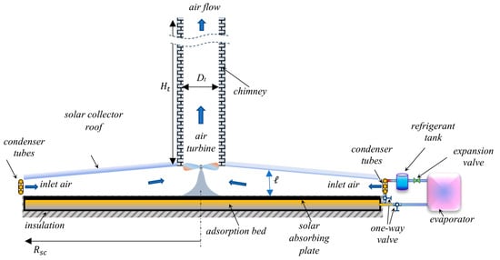
Figure 1.
An illustration of the geometry and components of the modified system.
The solar chimney power plant module consists of a large circular solar collector of outer radius and variable height . The roof height of the solar collector increases in the inward radial direction and reaches its maximum at the chimney, as illustrated in Figure 1. The height of the roof, , measured from the ground level, at any arbitrary radial location , is generally expressed by the following profile:
where is an exponent for the solar collector roof profile and is the outer radius of the solar collector. is the height of the roof at the periphery of the collector.
A tall vertical chimney of height , measured from the roof surface, and uniform internal diameter is constructed at the center of the solar collector. An axial-flow air turbine is centered inside the chimney at its entrance. The solar collector roof is made of transparent sheets of glass to pass and trap solar radiation.
The solar-powered adsorption-based cooling module consists of the following components: an adsorption reactor, an evaporator, a refrigerant condenser, an expansion valve, two one-way valves, and a liquid refrigerant receiving container. The adsorption reactor contains the adsorbent–adsorbate pair and is placed inside the solar collector under the transparent roof. The top surface of the adsorption bed is painted with black chrome to provide low emissivity and high solar radiation absorptivity. Consequently, the adsorption bed’s top surface acts as a solar radiation-absorbing plate. The adsorption reactor is thermally insulated from the bottom surface and the side edges. Hence, the absorbed solar radiation is transmitted to the adsorption bed as well as to the air stream inside the solar collector, resulting in a temperature increase in the air stream. The evaporator, the liquid refrigerant reservoir, and the valves are placed outside the solar collector. The refrigerant condenser tubes are placed at the entrance of the solar collector in a cross-flow with the inlet air stream. These tubes have a helical profile and are fixed along the circumference of the solar collector entrance.
The placement of the condenser tubes at the entrance of the solar collector allows for the capture of the condenser-released thermal energy by the air stream during the refrigerant condensation process. This recovered thermal energy causes an increase in the temperature of the air at the solar collector entrance. Hence, the air temperature rises through the solar collector, and the power generated by the air turbine in the chimney also increases. A further noteworthy benefit of the modified system presented in this paper is its independence from a water source for condenser cooling. This makes the modified system particularly suitable for desert climates. The significance of this characteristic is anticipated to amplify in the near future due to the projected escalation of desertification throughout extensive regions as a consequence of climate change. Furthermore, the position of the condenser tubes at the solar collector entrance provides enhanced cooling for the refrigerant vapor due to the forced convection effect, which is induced by the airflow entering the solar collector due to the chimney updraft effect. This method provides a rapid cooling and condensation process for the refrigerant vapor compared with the conventional condenser, which is cooled through natural convection.
2.2. The Operation of the Modified System
Both the solar chimney power plant module and the solar-powered adsorption-based cooling module work in parallel. The energy flow paths and energy exchanges between the two modules, as well as the energy exchanges between the combined system and the surroundings, are illustrated in Figure 2. The driving energy source for the two modules of the introduced hybrid system is incident solar radiation, . The operation of the system starts at sunrise, when the solar energy reaches the solar collector. A fraction of the incident solar radiation is transferred to the surroundings through radiation and convection due to the optical and heat transfer loss of the solar collector, . The solar collector absorbing plate absorbs the remaining portion. The net absorbed solar radiation is transferred to the airflow inside the solar collector as well as to the adsorption reactor. The thermal energy captured by the airflow under the roof of the solar collector, , causes a temperature increase in the airflow field towards the chimney in the inward radial direction. The airflow reaches its highest temperature at the exit of the solar collector and inlet of the chimney. The difference in air temperature between the inlet and the exit of the chimney causes a difference in air density. A natural airflow is created in the vertical direction inside the chimney due to the difference in air density between the bottom and the top of the chimney. The produced chimney updraft, due to the airflow inside the chimney, drives the air turbine, which is connected to an electric generator to produce electricity ().
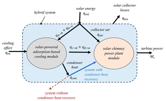
Figure 2.
An illustration of the energy flow paths and the energy exchanges for the present modified hybrid system.
The solar-powered adsorption-based cooling module operates in a cycle that comprises a sequence of four processes, as illustrated in Figure 3. The adsorption bed starts its first process, a→b, at sunrise. During this process, the bed is preheated and pressurized at a constant volume. The preheating process continues until the bed pressure increases from the evaporator pressure () to the condenser pressure (). The total thermal energy that is required to activate the adsorption reactor and bring the bed temperature to the desorption temperature, , is . The adsorption bed is automatically connected to the condenser through the condenser one-way valve when the bed pressure increases to the condenser pressure. The refrigerant vapor begins the isobaric desorption process, b→c, while the adsorption bed extracts the required heat of desorption from the solar collector absorber plate, . The release of refrigerant vapor from the reactor towards the condenser continues while the bed temperature increases due to the absorbed solar radiation.
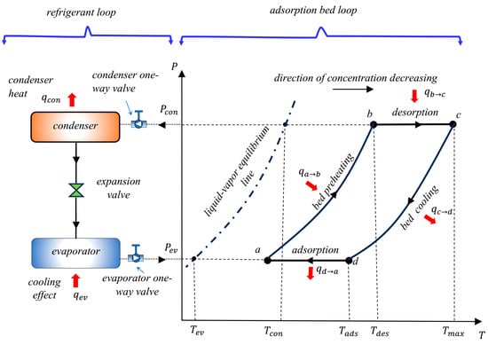
Figure 3.
The thermodynamic cycle of the adsorption-based cooling module.
The condensation of the refrigerant vapor in the condenser takes place during the desorption process. The refrigerant phase changes from gas to liquid in the condenser, and the corresponding heat of condensation, , is released by the condenser tubes. The refrigerant heat of condensation is transferred through convection to the air stream at the inlet of the solar collector. The heat of condensation is recovered from the condenser tubes by the air stream and is carried by the airflow into the solar collector. This recovered heat is then reused and recycled by the solar chimney power plant module, as shown in Figure 2. This results in an increase in the temperature of the airflow into the chimney. Consequently, the expected chimney updraft and the corresponding output power of the air turbine increase. The refrigerant desorption from the bed along with the condensation heat recovery processes continues until the temperature of the adsorption reactor increases from the desorption temperature, , to its peak, .
After the desorption process ends, the adsorption bed is automatically disconnected from the condenser through the condenser one-way valve because the bed pressure starts to decline. In the cooling and depressurization process, process c→d, the adsorption bed is cooled at a constant volume, as illustrated in Figure 3. The purpose of this process is to bring the reactor pressure back to the evaporator pressure. During this constant-volume cooling process, the adsorption bed transfers its thermal energy, , to the solar collector air stream. This thermal energy is recycled by the solar chimney power plant module and converted into power by the air turbine, as illustrated in Figure 2. When the bed pressure drops to the evaporator pressure and its temperature declines to the adsorption temperature, , the evaporator one-way valve opens to connect the bed with the evaporator and start the adsorption process, process d→a. This process takes place in parallel with cold production on the evaporator side, . The refrigerant adsorption process takes place at constant pressure, and the bed releases the heat of adsorption, , to the solar collector air stream. This released heat is reused by the solar chimney power plant module to drive the air turbine, as shown in Figure 2. Consequently, along with the refrigerant adsorption process and cold generation, the air turbine continues to produce power even after sunset and until the next day’s sunrise. Referring to Figure 2, a simple energy balance for the two-module integrated system gives for the condenser heat retrieval scenario, which is larger than for the other scenario without condenser heat regaining.
3. The Mathematical Model
The mathematical formulas that express and represent the introduced two-module hybrid system are coupled sets of nonlinear differential equations. In the following subsections, the governing mathematical equations and the corresponding numerical models that are implemented to simulate the components of the given hybrid system are introduced and explained.
3.1. Mathematical Modeling of the Adsorption Reactor
The mathematical modeling of the adsorption bed consists of two major governing equations: the conservation of mass for the refrigerant and the conservation of energy for the adsorption bed. Both the mass and energy balance equations are dependent on the thermodynamic process of the adsorption reactor, as shown in Figure 2. It is important to note that the behavior of the adsorption reactor is primarily influenced by the thermodynamic properties of the bed, such as temperature and pressure, rather than the velocity field of the adsorbate gas within the bed. Hence, the current simulation does not necessitate the inclusion of specific information regarding the velocity field of the refrigerant gas within the adsorption reactor. Therefore, the current mathematical modeling of the adsorption reactor does not necessitate the implementation of the equation of the conservation of momentum.
3.1.1. The Refrigerant Equation of Conservation of Mass
The bed-preheating and pressurization process, process a→b, and the bed-cooling and depressurization process, process c→d, take place at constant volume. During these two processes, the refrigerant mass inside the adsorption reactor remains constant. This is because the adsorption bed is isolated from both the condenser and the evaporator, and there are neither refrigerant flow inlets nor exits from the bed. The refrigerant inside the adsorption bed exists in two phases: the adsorbate phase and the gas phase. The refrigerant total mass is given by the sum of the refrigerant adsorbate phase mass, , and the refrigerant gas phase mass, . Consequently, the equation of the conservation of mass for the bed-preheating and bed-cooling processes can be expressed as
In the desorption process, process b→c, the refrigerant is released by the bed and flows towards the condenser. Therefore, the bed content of refrigerant decreases at a rate that equals the flow rate of the refrigerant into the condenser, . Hence, the refrigerant equation of conservation of mass for the reactor during the desorption process is written as
In the adsorption process, process c→a, the refrigerant is released by the evaporator and flows towards the adsorption reactor. The mass of refrigerant inside the adsorption reactor increases at a rate that equals the flow rate of the refrigerant out from the evaporator, . Hence, the refrigerant equation of conservation of mass for the reactor during the desorption process is written as
3.1.2. The Refrigerant Equation of Conservation of Energy
The energy equation of the adsorption reactor during the preheating and bed-cooling processes can be expressed as [5]
where is the density of the bed solid adsorbent, is the specific heat of the adsorbent material, is the porosity of the bed, is the adsorption bed temperature, is the volume of the reactor, is the refrigerant adsorbate phase density, is the refrigerant adsorbate phase specific internal energy, is the refrigerant gas phase density, is the refrigerant adsorbate phase volume fraction, and is the refrigerant gas phase specific internal energy. The term is the heat transferred through conduction from the solar collector absorber plate to the sorption bed. For a linear distribution of the adsorption bed temperature, can be expressed as [10]
where is the collector plate temperature and is the thermal resistance of the solid adsorbent. The volume of the reactor, , is given by
where is the adsorption bed thickness. The adsorbate phase volume fraction, , is expressed as [9]
where is the transient adsorbate phase concentration ratio. The linear driving force adsorption kinetic model expresses the transient uptake for the adsorbent particles in terms of as
where is the adsorbate equilibrium concentration ratio and is the internal mass transfer coefficient, which is expressed as
In the above equation, the parameters and have values that are dependent on the adsorption pair type. For the silica gel/water adsorption pair, and [84]. The adsorbate concentration ratio at equilibrium, , is given by [10]
where and are temperature-dependent coefficients, which are given by
For the silica gel/water adsorption pair, parameters and are given in Table 1.

Table 1.
Parameters and for the silica gel/water adsorption pair.
The refrigerant adsorbate phase specific internal energy, , is calculated as
where is the specific thermal energy of sorption, which is given by [85]
where is given by
The energy equation of the adsorption bed during the desorption process is given by
where is the specific enthalpy of the refrigerant gas that leaves the adsorption bed and flows towards the condenser. During the adsorption process, the energy equation of the sorption reactor is written as
where is the specific enthalpy of the refrigerant gas that leaves the evaporator and flows towards the adsorption reactor.
3.2. Mathematical Modeling of the Solar Collector
The condenser tubes of the cooling module are installed at the entrance of the solar collector. During the desorption process inside the adsorption reactor, the condensation process of the refrigerant vapor inside the condenser takes place in parallel. The airflow crossing the condenser tubes captures the heat of condensation, , before it enters the solar collector. Consequently, the air enters the solar collector at a higher temperature, , than the ambient temperature, .
The process of retrieving the condenser heat and the airflow conditions before and after the condenser are schematically illustrated in Figure 4. The static temperature of the airflow before the condenser tubes is determined in terms of the air velocity as
where is the atmospheric temperature and is the air velocity in the inward radial direction. The static pressure of the airflow before the condenser tubes is given by the following isentropic relation:
where is the air specific heat ratio. The heat of condensation, , which is released by the condenser tubes, is determined as
where is the mass flow rate of the refrigerant vapor, is the specific enthalpy of the refrigerant vapor that desorbs from the adsorption bed, and is the specific enthalpy of the condensate refrigerant liquid corresponding to the condenser pressure.
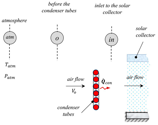
Figure 4.
Inlet conditions for the solar collector and condenser heat recapture.
The stagnation temperature of the air stream after the condenser tubes and inlet of the solar collector is determined from the energy balance with the following equation:
where is the air mass flow rate and is the air specific heat at constant pressure. The static temperature of the air stream at the solar collector inlet is given by
where is the air velocity at the solar collector inlet. Neglecting the loss in total pressure, the airflow static pressure at the collector entrance is then determined as
The combined system heat transfer components are illustrated on a differential control volume at radial distance that includes the solar collector and the adsorption bed, as shown in Figure 5. In addition, the corresponding equivalent thermal resistance network that represents the heat flow paths at each node is sketched in Figure 6.
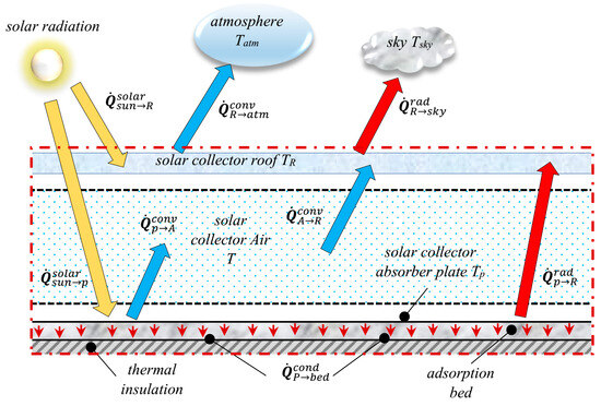
Figure 5.
A differential control volume of the solar collector and the adsorption bed at radial distance showing heat transfer components of the combined system.
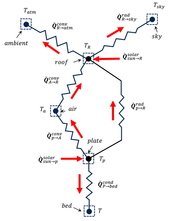
Figure 6.
Thermal resistance network and heat flow paths.
The density of air is calculated from the ideal gas equation of state.
where is the static pressure of air and is the static temperature of air. The mass flow rate of the air is determined at any radial location as
where is the airflow density; is the velocity of the air stream; and is the flow area at radius , given by
where is the solar collector roof height at radius .
The temperature equation for the airflow can be obtained from the energy balance for the differential control volume as follows:
In the above equation, is the constant-volume specific heat of air, is the temperature of the collector plate, and is the temperature of the solar collector cover. The convective heat transfer coefficients, and , are determined with the method reported in references [3,86].
The equation of the solar absorbing plate temperature can be found by applying the principle of conservation of energy to the control-volume element illustrated in Figure 5. This equation can be written as
In this equation, is the heat transfer between the absorbing plate and the adsorption bed, and is the surface area of the absorbing plate. The radiative heat transfer coefficient, , is expressed as
where is the emissivity of the absorber plate and is the emissivity of the solar collector roof.
From Figure 5 and Figure 6, the solar collector roof temperature can be obtained from the energy balance for the transparent cover as
The temperature of the sky, , is given by [87]
where is the atmospheric temperature. The heat transfer coefficient, , is determined as
where is the Stefan–Boltzmann constant. The convection coefficient, , is expressed as [88]
where is the wind velocity.
The generated power from the turbine is given by [89]
where is the turbine efficiency, is the chimney cross-sectional area, is the airflow velocity in the chimney, and is the chimney maximum updraft. The chimney air velocity is calculated as [89,90]
where is , is the height of the chimney, and is the collector air total temperature rise. The maximum chimney pressure potential is determined as [90]
where is the chimney airflow density at the inlet.
4. The Climatic Data and the Values of the Simulation Parameters
In order to obtain the solution to the aforementioned mathematical model, climatic data are required. These climatic data represent the hourly solar radiation, the hourly atmospheric temperature, and the hourly wind speed. It is well known that the climate depends on the time of day as well as the location. Furthermore, the climatic data variation with the time of day and with the day of the year has a random profile. The climatic data that are used in the current study were taken from NASA [91]. For an arbitrary location, Riyadh, and an arbitrary date, 20 August 2022, the climatic data are given in Table 2. A case study is proposed to facilitate the simulation and quantitative calculation of performance parameters. The baseline parameters of the analyzed case are provided in Table 3. Several of these baseline parameters pertain to thermophysical properties and coefficients, including the specific heat, density, and thermal conductivity of silica gel, among others. The remaining set of baseline characteristics was selected arbitrarily, including the collector radius, turbine efficiency, chimney height, chimney diameter, and other factors. It is worth noting that the selection of these specific numbers for the baseline parameters in Table 3 was arbitrary and not based on any specific rationale. Moreover, these values do not correspond to the optimal design parameters of the system; rather, they were selected arbitrarily solely for the purpose of simulating the system.
Table 2.
The climatic data that are used in the current study.
Table 3.
Values of the baseline parameters that are employed in the present case-study simulation.
5. The Numerical Model and the Solution Assumptions
The abovementioned mathematical model and equations were solved numerically by implementing the finite difference approach. A programming code was written in MATLAB to dynamically simulate the behavior of the introduced physical system and calculate its performance. Since the hybrid system under study is significantly affected by the climatic conditions, it was assumed that the system is subjected to the same climatic conditions during every complete operating cycle, as given in Table 2. Consequently, the simulated system’s operating cycles are repetitive and identical. Moreover, the initial conditions for the current cycle are similar to the final conditions of the previous cycle. In other words, for a similar repetitive operating cycle, the simulated system shows steady-state periodic cycles in which the initial conditions are identical to the final conditions. Therefore, an iterative procedure was implemented in the programming code to search for the initial conditions of the simulated system operating cycle. The solution assumptions include the following:
- Once the refrigerant vapor desorbs from the bed, it condenses inside the condenser tubes.
- All the heat of condensation is transferred to the air stream that crosses the condenser tubes and moves towards the entrance of the solar collector without any thermal loss.
- The thermodynamic properties of water are extracted from the tabulated data.
- One-dimensional heat transfer in the radial direction is considered.
- The sorption bed has perfect thermal insulation from the bottom as well as from side edges to prevent loss of heat to the ground.
- The sorption reactor is modeled as a lumped system that has uniform pressure and temperature distributions.
- Heat capacity effects of the roof and the absorber plate are ignored.
6. Results and Discussion
The presented results comprise the performance and operation behavior of the combined solar chimney power plant and adsorption cooling system in two cases: the modified system that retrieves condenser heat and the basic system without condenser heat regaining. The time allocation, schedule of the different system operations, and periods of various cycle processes are illustrated by the timeline chart in Figure 7 for the presented modified system, with condenser heat retrieval, and the original basic system, without heat recapture. The complete cycle of both the modified and basic systems begins at sunrise at 05:37 and continues the operation for a period of 24 h. Solar radiation extends from 05:37 to 18:23 for a period of 12.77 h and reaches its peak of at 11:00. The total solar thermal energy that falls on the solar collector roof is found to be during the system operating cycle. The operation of the air turbine extends over the whole 24 h period of the operating cycle in both the modified system and the basic system. It is obvious that the adsorption bed-preheating–pressurization process comes before the desorption and condensation processes. The notion that the adsorption reactor-preheating–pressurization process is not influenced by condenser heat recapture is not accurate. As presented by the timeline chart in Figure 7, the preheating–pressurization process of the adsorption rector is found to be 3 min longer in the case of the modified system compared with the basic system. This is because the amount of refrigerant mass inside the adsorption bed of the system with condenser heat recirculation is smaller than the corresponding amount for the basic system. The desorption and condensation processes for the modified system with condenser heat reuse continue for 4.95 h and end at 13:55, which is 22 min earlier than the end of the same processes in the basic system without condenser heat reuse. Therefore, the effect of condenser heat recycling is clearly noticed in accelerating refrigerant desorption from the adsorption reactor. The acceleration of refrigerant desorption from the bed in the modified system has an impact on the other following bed processes. It is obvious from the timeline chart in Figure 7 that the bed-cooling–depressurization process is 3 min faster and ends earlier, at 18:03, in the modified system compared with the basic system, whose process ends at 18:17. This justifies the earlier and longer evaporator cooling effect, which is associated with the 14 min longer bed adsorption period for the system with condenser heat regaining compared with the basic system without condenser heat retrieval.
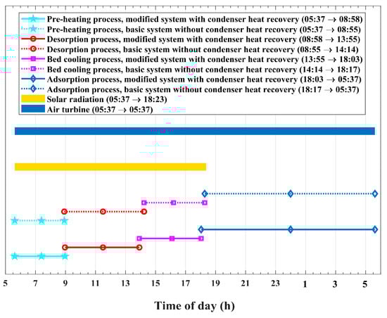
Figure 7.
The timeline chart, showing time allocation and operational schedule of the modified and basic system processes.
Figure 8 shows the temporal changes in refrigerant condensation heat, , which is released inside the condenser tubes by the vapor that desorbs from the bed. One plotted profile represents the temporal variation in the released and recycled condensation heat for the modified system, and the other plotted profile represents the temporal variation in the released condensation heat for the basic system, which is dumped into the atmosphere. Figure 9 plots the corresponding time-integrated released condensation thermal energy at the condenser. As illustrated in Figure 8 and Figure 9, the evidence that the released heat of condensation is affected by the process of condenser heat recapture is pronounced. The differences between the condenser-released heat with and without heat recovery are obvious, and they deserve thorough investigation. For the modified system, with condensation heat reutilizing, the desorption–condensation operation ends earlier, at 13:55, compared with the corresponding operation in the basic system, which takes longer and ends at 14:14. Moreover, higher rates of released enthalpy of condensation are noticed for the modified system, which reuses condenser heat. The major reason behind these differences is that the recycled refrigerant enthalpy of condensation acts as an additional thermal energy source that assists the absorbed solar radiation and accelerates the process of refrigerant desorption from the adsorption reactor. Furthermore, this extra heat source produces a further increase in the adsorption pair temperature. Consequently, in the case of the heat reuse system, a larger amount of refrigerant vapor is freed from the adsorption bed and transfers to the condenser tubes compared with the system without heat recirculation. Hence, this larger amount of desorbed refrigerant vapor explains why the released condenser heat is higher for the modified system compared with the corresponding heat for the basic system.
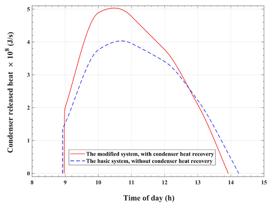
Figure 8.
The heat of condensation that is released by the refrigerant vapor in the condenser.
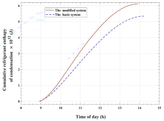
Figure 9.
Time-accumulated refrigerant vapor enthalpy of condensation.
The influence of condenser heat reuse on the airflow total temperature at the solar collector inlet is illustrated in Figure 10. It is apparent that the air total temperature at the solar collector inlet, , has a time-varying profile that coincides with the atmospheric temperature variation pattern for the basic system. However, a temperature rise above that of the atmosphere is observed during the desorption and condensation periods in the case of the modified system. The air temperature profile shows a temporal variation pattern that matches the variation profile of the recycled condensation heat, as given in Figure 8. The peak of the inlet air total temperature is approximately 53.6 °C and is noticed at 10:43 in the day. This increase in air total temperature at the solar collector inlet for the modified system compared with the basic system is a result of the recycled condenser thermal energy.
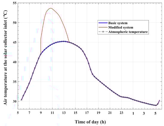
Figure 10.
Variations in the airflow temperature at the solar collector inlet with the time of day.
Table 4 compares the values of the thermal energy components obtained for various thermodynamic processes of the adsorption cooling module for the introduced enhanced system and the original basic system. It is found that the total amount of thermal energy absorbed by the adsorption reactor during the preheating and desorption processes, , is for the modified system, compared with a value of for the basic system. The time-accumulated thermal energy that is released by the refrigerant condensation process, , is found to be for the enhanced system, which is larger compared with the corresponding amount of for the basic reference system. Therefore, the system without condenser heat recirculation wastes an amount of thermal energy that equals approximately 68.2% of the total activation thermal energy that is required to release the refrigerant vapor from the reactor. However, the present improved system, with condenser heat recycling, recirculates and reuses this amount of thermal energy, which is found to be 77.9% of the total thermal energy required to release refrigerant vapor from the reactor of the basic reference system. Furthermore, an increase of approximately 14.2% in the enthalpy of condensation is obtained by the present improved system with condenser heat reuse compared with the unmodified basic system. Consequently, the modified system presents a double-effect enhancement. This means that the process of condenser heat retrieval not only allows for the reuse of the basic system’s wasted condensation enthalpy but also causes an augmentation in the recycled condensation thermal energy. The thermal energy ejected by the adsorption reactor during the depressurization and adsorption processes, , is transferred to the air stream under the solar collector. This thermal energy causes a temperature increase in the solar collector air, which, as a result, produces an increase in the chimney updraft and pressure potential. It can be seen from the data in Table 4 that the adsorption reactor releases a larger amount of thermal energy, , in the scenario of condensation enthalpy reutilization compared with the corresponding amount of in the basic system scenario with condensation heat wasting. In other words, the enhanced and modified system, which allows condensation heat to be recirculated, produces approximately 10.7% excess thermal energy, which is dissipated by the adsorption reactor during the depressurization and adsorption operations, compared with the basic system. It can also be noticed in Table 4 that the cooling effect for the system with condenser heat recirculation is about 14.2% larger than that for the unmodified original system, which ejects the condensation thermal energy into the environment.
Table 4.
Components of the thermal energy interactions as calculated for the adsorption cooling module.
The changes in refrigerant mass within the adsorption bed with respect to the time of day during the desorption and condensation processes are shown in Figure 11. The variations in the desorbed refrigerant mass flow rate with the time of day are plotted in Figure 12. These figures compare the refrigerant mass profile of the present improved system and the corresponding profile of the original reference system. The adsorption reactor begins the desorption process with initial refrigerant mass contents of approximately and for the modified system and the reference basic system, respectively. The refrigerant mass inside the bed of the modified system is nearly 2.2% less than the same mass for the unmodified basic system. This slight difference is due to the slightly higher initial bed temperature in the modified system, which is precisely 35.42 °C, compared with that of the basic system, which is approximately 35.0 °C. As illustrated in Figure 11, both compared systems show decreasing profiles of bed refrigerant mass content during the isobaric desorption process. However, the bed refrigerant mass content decreasing rate is higher for the system that recirculates the condensation heat compared with the other reference system. As is apparent in Figure 12, both the modified and the basic systems attain comparable temporal variation behavior for the desorbed refrigerant mass flow rate. At the start of the desorption process, both profiles show an abrupt jump from a zero mass flow rate to a starting value of 80 kg/s for the modified system and 55 kg/s for the basic system. Thereafter, the refrigerant mass flow rate shows a continuous increasing profile before reaching a peak value, after which it starts to decline until the desorption process ends. This behavior of desorbed mass flow rates results in comparable profiles and corresponding peaks for the condenser-released heat, as is evident in Figure 8. As can be noticed in Figure 12, the peak of the desorbed refrigerant mass flow rate from the bed takes place at 10:28, with a rate of 204 kg/s for the modified version of the system. This corresponds to a peak with a rate of 163.5 kg/s that takes place at 10:41 for the basic reference system. The higher values of desorbed mass of refrigerant vapor in the modified system can be explained by the effect of reused condenser thermal energy, which causes higher levels of bed temperature compared with the basic reference system. At the end of the desorption process, the mass of water inside the adsorption bed is found to be approximately for the introduced modified system compared with approximately for the unmodified basic system. In other words, the adsorption reactor releases of refrigerant vapor to the condenser in the present enhanced system, which reuses condenser heat, compared with in the system conventional version, which dissipates condenser heat into the environment. Therefore, an approximately 14.2% increase in desorbed refrigerant mass from the sorption reactor can be achieved with the introduced modification, whereby the system recycles the refrigerant vapor enthalpy of condensation. Moreover, this increase in desorbed mass causes a corresponding, equal increase in recycled condensation heat, as previously discussed in relation to the data provided in Table 4.
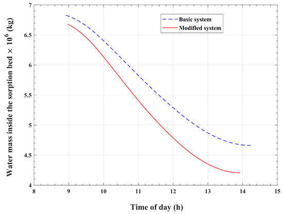
Figure 11.
Temporal variations in the water mass within the adsorption bed during the desorption and condensation processes.
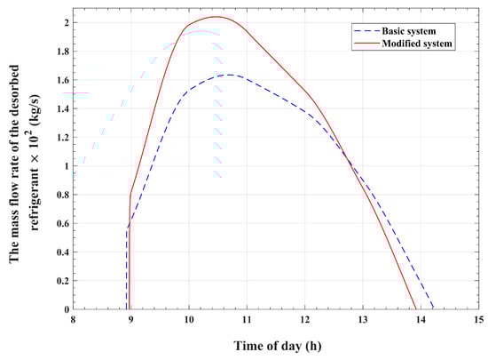
Figure 12.
Variations in the mass flow rate of the desorbed water vapor with the time of day.
The changes in refrigerant mass within the adsorption bed with time during the isobaric adsorption and cold production processes are illustrated in Figure 13 for the basic and modified systems. The results show that the bed refrigerant mass increases from to in the modified system, which corresponds to an increase from to in the basic system. Consequently, the effective amount of refrigerant vapor that circulates inside the cooling module, between the evaporator and the condenser, and produces the cooling effect is approximately for the modified system, which is larger compared with the corresponding amount of approximately for the basic reference system. This represents an increase of approximately 14.2% in the effective refrigerant mass in the present improved system, which recycles condenser heat, compared with the corresponding mass in the basic system, which wastes the refrigerant heat of condensation. Moreover, the ratio between the refrigerant effective mass and the initial refrigerant mass content of the reactor is found to be 37% for the modified system, which is higher compared with the corresponding value of 32% for the basic system. This means that the present modified system utilizes the refrigerant content of the adsorption reactor in a more efficient way compared with the basic system. Figure 14 compares the refrigerant-adsorbed mass flow rate for the present enhanced system with that of the reference basic system. It can be noticed from the plots in Figure 14 that the modified system attains pronouncedly higher values of mass flow rates at all times compared with the corresponding values for the reference basic system. Therefore, as demonstrated in Figure 15, the corresponding cooling effect attains an increased value of for the modified system over a corresponding value of for the unmodified reference system. Therefore, a 14.2% increase in the evaporator cooling effect can be obtained with the modified system compared with the basic system. The coefficient of performance (COP) is one of the performance indicators of cooling systems. The COP is defined as the ratio between the cooling effect at the evaporator and the total heat that is required to generate the refrigerant from the adsorption bed during the pressurization and desorption processes. It is found that the COP for the presented enhanced system is approximately 0.67, which is higher compared with the COP value of 0.64 for the basic system.
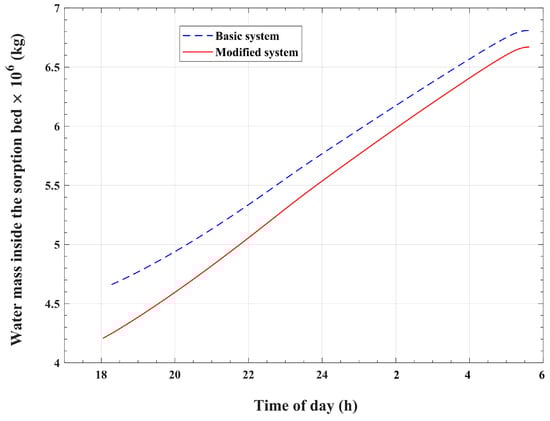
Figure 13.
Temporal variations in the refrigerant mass within the adsorption bed during the adsorption process.
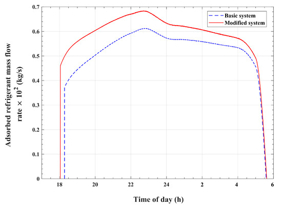
Figure 14.
Variations in the mass flow rate of the adsorbed refrigerant with the time of day.
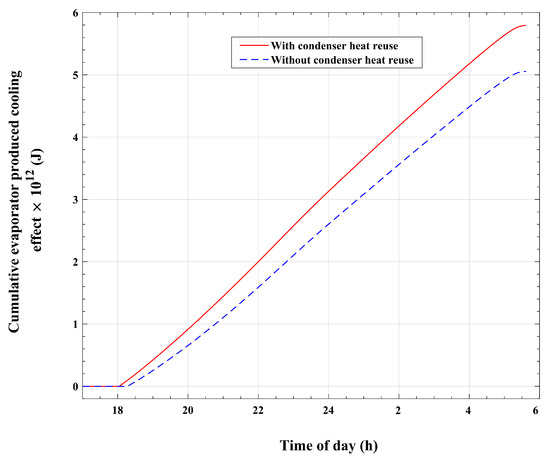
Figure 15.
Variations in the cumulative cooling effect at the evaporator with the time of day.
The changes in the temperature of the refrigerant inside the adsorption reactor with the time of day for the present improved system as well as the original basic system are demonstrated in Figure 16. As is apparent in this figure, both systems generally exhibit similar temperature behavior during the operating cycle. Nonetheless, the adsorption reactor of the system with condenser heat recirculation acquires a higher temperature increasing trend during the desorption and adsorption processes compared with the basic system temperature profile. During the desorption–condensation operations, the adsorption bed attains a maximum temperature of approximately 77.6 °C at 13:55 for the modified system, which is 1.9 °C higher when compared with about 75.7 °C at 14:14 for the original basic system. It is obvious that this 1.9 °C difference in temperature is mainly due to the impact of the extracted and reused refrigerant vapor condensation enthalpy. Furthermore, the plotted temperature profile of the modified system during the adsorption process generally indicates higher temperature values compared with the original basic system. This trend can be explained by the effect of the larger amount of adsorption bed-released sorption heat, which corresponds to a larger amount of adsorbed refrigerant vapor compared with the basic system.
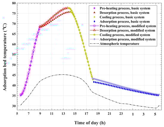
Figure 16.
Variations in adsorption bed temperature with time.
Figure 17 compares the temporal changes in the thermal energy that is carried by the airflow under the solar collector roof in the modified system and the basic system. Moreover, the time accumulation of this thermal energy is plotted in Figure 18 for the presented system and the basic system. It is apparent that the modified system obtains higher values of the amount of thermal energy carried by the collector airflow compared with the basic system. By the end of the operating cycle, the airflow of the modified system is found to gain about thermal energy compared with the corresponding amount of about of the basic system. This represents a value of 5.95% increase compared with the thermal energy gained by the basic system. As a result, the airflow under the transparent roof of the solar collector is expected to attain higher temperatures in the case of the modified system compared with the case of the basic system. This influence is obvious in Figure 19, which compares the temporal variations in airflow temperatures at the exit of the solar collector and inlet of the chimney for the modified system and those for the basic system. The plots show remarkable higher temperatures at the chimney inlet for the modified system compared with the reference basic system during the desorption and condensation operations. This noticeable temperature difference is a direct result of the recirculation and reutilization of condensation thermal energy. Furthermore, a slight increase in the chimney inlet airflow temperatures is seen during the adsorption and cold production processes. This increase is directly caused by the larger adsorbed refrigerant amount and the corresponding increased heat of adsorption, as explained in Figure 13, for the modified system compared with the basic system, which is indirectly related to condenser heat recycling.
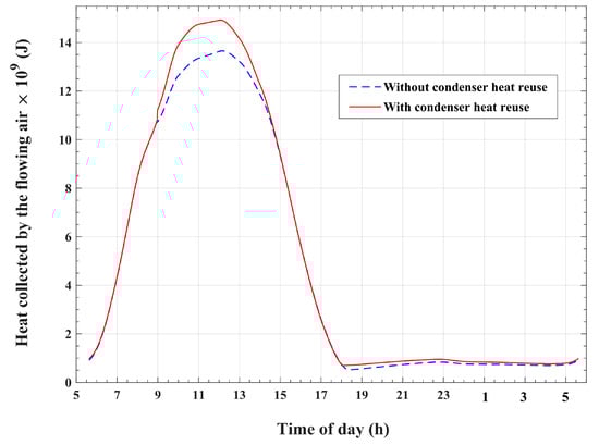
Figure 17.
Variations in thermal energy that is carried by the airflow with the time of day.
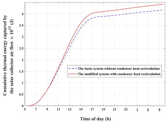
Figure 18.
The cumulative thermal energy that is carried by the airflow.
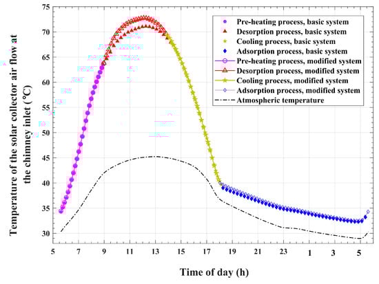
Figure 19.
Variations in airflow temperatures at the solar collector exit and chimney inlet with the time of day.
In order to meticulously scrutinize the spatial variations in the airflow parameters inside the solar collector from its inlet to its exit, two instantaneous snapshots are taken at two arbitrary time points. One time point is taken to be within the desorption and condensation period, at 12:00, whereas the other time point is taken to be within the adsorption and cold generation period, at 21:00. The variations in the solar collector airflow temperatures in the radial direction at the 12:00 and 21:00 times of day are plotted in Figure 20 for the modified and basic systems. Generally, an increasing trend is pronounced for all the plotted variations in air temperature in the inward radial direction. This increasing trend in air temperature can be justified by the continuous thermal energy transferred from the solar absorber plate to the air stream while the air moves from the solar collector inlet to its exit in the inward radial direction. Nonetheless, the gradients in air temperature are higher at the solar collector outer radii compared with these gradients in temperature at positions at inner radii, and this applies to all the temperature profiles, as illustrated in Figure 20. In other words, the airflow temperature gradients decrease in the inward direction of the solar collector. This is because of the decrease in the amount of heat transferred from the solar-absorbing plate to the airflow due to the decrease in the plate surface area in the inward radial direction. Furthermore, the behavior of airflow temperature gradients varies depending on the system as well as the time of day.
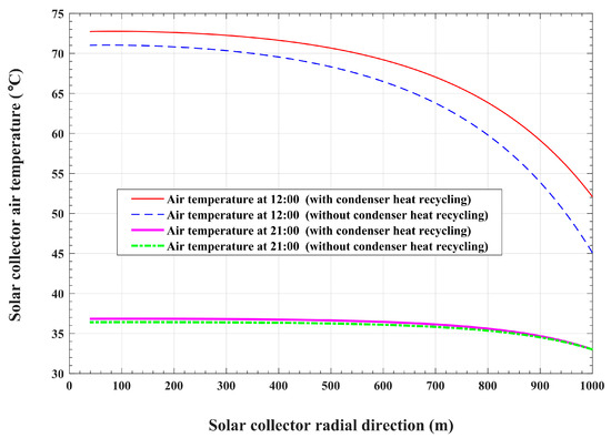
Figure 20.
Radial variations in the solar collector airflow temperatures.
At 12:00, both the modified and the basic systems undergo desorption and condensation operations. In the meantime, the absorber plate collects solar radiation and transfers heat to the airflow. For the basic system, which dissipates condensation heat into the environment, the heat transferred from the absorber plate is the only source that causes an increase in air temperature. As shown in Figure 20, the airflow temperature increases from 45 °C, which equals the ambient temperature at 12:00, at the collector inlet to 71 °C at its exit in the basic system at 12:00, whereas the modified system acquires an excess amount of transferred heat compared with the heat that is gained by the basic system. This excess heat is obtained through the process of condenser heat recirculation and reuse. The influence of condenser heat recycling in the case of the modified system is pronounced at the inlet boundary of the solar collector. A higher value of inlet air temperature of 52 °C is obtained in the modified system because of condenser heat reutilization compared with 45 °C in the basic system. At the exit of the collector, the modified system attains an airflow temperature of 72.7 °C. As a result, the modified system gains a 1.7 °C rise in solar collector temperature compared with the basic system due to condenser heat recirculation. It can also be noticed that for the modified system, the airflow temperature increases by two times. The first increase, which is obtained across the condenser, is of 7 °C, and the second increase, which is gained across the solar collector, is of 20.7 °C. On the other hand, the basic system gains an increase in airflow temperature across the solar collector of 26 °C, compared with 20.7 °C for the modified system. This is because a larger amount of refrigerant is released by the bed, and consequently, a larger amount of heat is consumed by the reactor in the case of the modified system compared with the basic system, as previously discussed in relation to the data given in Table 4.
With regard to the airflow temperature spatial variations at 21:00, during the adsorption and cold generation operations, the temperature gradients are noticed to be lower than the corresponding gradients at 12:00 for the two systems. The only driving source of heat for both the modified and basic systems is the corresponding adsorption bed-released heat, which is larger in the case of the modified system compared with the basic system, as previously discussed with the data given in Table 4. This results in a slight increase in the airflow temperature of the modified system compared with the basic system. Since there is no recycled condensation heat during the adsorption process, the airflow enters the solar collector at the ambient temperature of 33 °C in both system cases. The air stream temperatures at the exit of the collector are found to be 36.8 °C for the modified system and 36.4 °C for the basic system. This slight increase, of about 0.4 °C, is due to the larger amount of adsorbed refrigerant in the case of the modified system, which releases a larger amount of sorption heat into the air stream compared with the basic system.
Figure 21 compares the spatial variations in the solar collector airflow velocities in the radial direction for the modified system with the corresponding airflow velocities in the basic reference system at the 12:00 and 21:00 times of day. As can be noticed in the figure, the plotted velocities show continuous increases in values with increasing gradients in the inward direction. These increased velocity values and increased velocity gradients are mainly related to two reasons. The first reason is the influence of the flow passage, which converts in the direction towards the center of the solar collector. The second reason is the continuous increase in airflow temperature in the inward radial direction, as discussed for the results in Figure 20. This increase in airflow temperature causes a corresponding decrease in air density. Therefore, to conserve the mass flow rate, the air volume flow rate and the air velocity should increase in the inward radial direction. As can be seen from Figure 21, the presented modified system obtains slightly larger values of airflow velocities at all radii as well as at all times compared with the basic system.
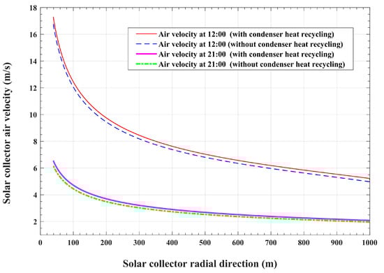
Figure 21.
Variations in the solar collector airflow velocity in the radial direction.
The influence of condenser heat recycling on the air turbine-produced power is illustrated in Figure 22. This figure compares the turbine-generated power of the modified system with that of the basic system at all times during the cycle of operation. It can be noticed that the power curve of the modified system attains higher values compared with the basic system during the desorption and condensation operations. Furthermore, a slight increase in air turbine output power is observed for the modified system compared with the basic system during the adsorption process. It is also found that the total power generated by the turbine reaches a value of 96.915 MWh for the presented system, compared with power generation of about 91.47 MWh for the reference system. Therefore, an approximately 5.445 MWh increase in turbine power is obtained with the modified system compared with the basic reference system. This means that a 5.95% increase in output power can be achieved through the recirculation and reutilization of the heat of condensation. Most of this increase in turbine power, approximately 78.05%, is obtained during the desorption and condensation operations, and 18.33% of this increase is obtained during the adsorption and cold production operations. It is also found that during the pressurization and depressurization processes, there are no observed significant increases in the turbine-generated power in the modified system compared with the basic system. Furthermore, the increase in turbine power corresponds to an improvement in solar-to-electricity efficiency. Solar-to-electricity efficiency is defined as the percentage of the turbine that produces electric energy out of the total incident solar thermal energy. The modified system attains a solar-to-electricity efficiency rate of about 0.424%, compared with the corresponding value of 0.4% for the basic system. This represents an increase of 6% in solar-to-electricity efficiency with the modified system compared with the basic system.
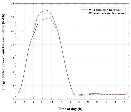
Figure 22.
Variations in the power produced by the air turbine with the time of day.
7. Conclusions
Solar updraft tower power plants promote the utilization of sustainable energy sources owing to their cost effectiveness, minimal maintenance requirements, and environmentally friendly nature. Nevertheless, despite extensive endeavors to enhance the design of these plants, their energy conversion efficiency and capacity for power generation continue to be constrained. Scholars have conducted investigations into alterations in plant geometry and hybridization techniques in order to enhance energy conversion efficiency. A solar chimney power plant integrated with an adsorption cooling system for power and cold cogeneration was first introduced in a previous work [3]. This hybrid system was an integral part of two modules. The first module represents a solar chimney power plant. The second module is a solar-driven adsorption cold-generating system. The adsorption bed is placed under the transparent roof of the solar collector in order to recycle the heat released by the adsorption bed during bed depressurization and adsorption operations. It was proven, in this previous work, that reusing the heat released by the adsorption bed enhances the system’s utilization of solar energy and increases the turbine output power by a value of 3.22%. In addition, solar-to-electricity efficiency was found to be 0.4%.
In the present paper, an additional modification to the preceding basic system’s arrangement and operation is introduced. The reason for this modification is to attain an additional performance improvement over the basic reference system and to optimize the consumption of solar energy. The modification is performed by placing the condenser tubes in a cross-flow with the inlet air stream. These tubes have a helical profile and are fixed along the circumference of the solar collector entrance. This modified configuration permits the capture of the heat of condensation by the solar collector airflow. This operation takes place during the refrigerant desorption and condensation processes. The recovered condenser heat causes an increase in the temperature of the solar collector inlet airflow. This causes a temperature rise in the airflow exit of the collector and an increase in the power generated by the air turbine. Another benefit of the introduced system is that it does not require a water source for condenser cooling, making it particularly suitable for desert climates. The significance of this characteristic is anticipated to amplify in the near future due to the projected escalation of desertification throughout extensive regions as a consequence of climate change. Furthermore, the position of the condenser tubes at the solar collector entrance provides enhanced cooling for the refrigerant vapor due to the forced convection effect, which is induced by the airflow entering the solar collector due to the chimney updraft effect. This method provides a rapid cooling and condensation process for the refrigerant vapor compared with the conventional condenser, which is cooled through natural convection.
The configuration and operation of the present modified system are introduced. A dynamic mathematical model for the combined solar collector and the adsorption cooling modules is established to simulate the hybrid system’s operation and evaluate its parameters. The adsorption pair that is used in this work is silica gel and water. The climatic data used in the simulation represent the hourly solar radiation, the hourly atmospheric temperature, and the hourly wind speed.
The process of condenser heat regaining not only allows for the reuse of the basic system’s wasted condensation enthalpy but also causes an augmentation in the recycled condensation thermal energy. It is found that the modified system recirculates and reuses an amount of thermal energy that is about 77.9% of the total thermal energy required to release refrigerant vapor from the reactor of the basic reference system. Moreover, an increase of approximately 14.2% in condenser-released heat is obtained through condenser heat recycling. Furthermore, the modified system produces about 10.7% excess thermal energy, which is dissipated by the adsorption reactor during the depressurization and adsorption operations, compared with the basic system. It is also found that the cooling effect for the system with condenser heat recirculation is approximately 14.2% larger than that of the unmodified basic system, which ejects the condensation thermal energy into the environment. Moreover, the ratio between the refrigerant effective mass and the initial refrigerant mass content of the reactor is found to reach a value of 37% for the modified system, which is higher compared with the corresponding value of 32% for the basic system. Furthermore, a 5.95% increase in output power can be achieved through the reutilization of the heat of condensation. In addition, the modified system attains a 6% increase in solar-to-electricity efficiency compared with the basic system. The findings suggest that the modified system, which recycles condenser heat, provides noticeable enhanced performance compared with the basic system.
Although the modified system provides more power than the basic system after sunset, the amount of this power is lower after sunset than it is during the day. Hence, this causes a restriction on the system’s operation and reduces its dependency on the system’s produced power after sunset. Therefore, it is necessary to conduct more research in order to get round this restriction. Future research will examine the system’s sensitivity to parameter variation in order to identify the system’s optimal design parameters and operating constraints. Additionally, we will look into integrating the suggested technology with additional uses, like desalination and/or thermal energy storage.
Funding
This research received no external funding.
Data Availability Statement
Data are contained within the article.
Conflicts of Interest
The author declares no conflicts of interest.
References
- Ali, M.H.; Kurjak, Z.; Beke, J. Modelling and Simulation of Solar Chimney Power Plants in Hot and Arid Regions Using Experimental Weather Conditions. Int. J. Thermofluids 2023, 20, 100434. [Google Scholar] [CrossRef]
- Kumar Mandal, D.; Biswas, N.; Manna, N.K.; Benim, A.C. Impact of Chimney Divergence and Sloped Absorber on Energy Efficacy of a Solar Chimney Power Plant (SCPP). Ain Shams Eng. J. 2023, 15, 102390. [Google Scholar] [CrossRef]
- Hassan, H.Z. Transient Analysis of a Solar Chimney Power Plant Integrated with a Solid-Sorption Cooling System for Combined Power and Chilled Water Production. Energies 2022, 15, 6793. [Google Scholar] [CrossRef]
- Ghafoor, A.; Munir, A. Worldwide Overview of Solar Thermal Cooling Technologies. Renew. Sustain. Energy Rev. 2015, 43, 763–774. [Google Scholar] [CrossRef]
- Hassan, H.Z.; Mohamad, A.A.; Al-Ansary, H.A.; Alyousef, Y.M. Dynamic Analysis of the CTAR (Constant Temperature Adsorption Refrigeration) Cycle. Energy 2014, 77, 852–858. [Google Scholar] [CrossRef]
- Hassan, H.Z.; Atteia, G.E. Controlled Strategy for the Cooling Effect of the Solar-Driven Constant-Temperature Solid Sorption System. Int. Rev. Mech. Eng. (IREME) 2021, 15, 464–474. [Google Scholar] [CrossRef]
- Aristov, Y.I. Adsorptive Conversion of Ultralow-Temperature Heat: Thermodynamic Issues. Energy 2021, 236, 121892. [Google Scholar] [CrossRef]
- Chauhan, P.R.; Kaushik, S.C.; Tyagi, S.K. A Review on Thermal Performance Enhancement of Green Cooling System Using Different Adsorbent/Refrigerant Pairs. Energy Convers. Manag. X 2022, 14, 100225. [Google Scholar] [CrossRef]
- Hassan, H.Z. Sensitivity Analysis of the CO-SAR Machine. Int. Rev. Mech. Eng. (IREME) 2015, 9, 21–30. [Google Scholar] [CrossRef]
- Hassan, H.Z. Assessment of the Adsorber Surface Density Influence on the Performance and Operation of the Intermittent SAR System. Energy Convers. Manag. 2015, 94, 19–27. [Google Scholar] [CrossRef]
- Dias, J.M.S.; Costa, V.A.F. Adsorption Cooler Design, Dynamic Modeling, and Performance Analyses. Clean Technol. 2022, 4, 1152–1161. [Google Scholar] [CrossRef]
- Chauhan, P.R.; Kaushik, S.C.; Tyagi, S.K. Current Status and Technological Advancements in Adsorption Refrigeration Systems: A Review. Renew. Sustain. Energy Rev. 2022, 154, 111808. [Google Scholar] [CrossRef]
- Sah, R.P.; Choudhury, B.; Das, R.K. A Review on Low Grade Heat Powered Adsorption Cooling Systems for Ice Production. Renew. Sustain. Energy Rev. 2016, 62, 109–120. [Google Scholar] [CrossRef]
- Makahleh, F.M.; Badran, A.A.; Attar, H.; Amer, A.; Al-Maaitah, A.A. Modeling and Simulation of a Two-Stage Air Cooled Adsorption Chiller with Heat Recovery Part I: Physical and Mathematical Performance Model. Appl. Sci. 2022, 12, 6542. [Google Scholar] [CrossRef]
- Makahleh, F.M.; Badran, A.A.; Attar, H.; Amer, A.; Al-Maaitah, A.A. Modeling and Simulation of a Two-Stage Air-Cooled Adsorption Chiller with Heat Recovery Part II: Parametric Study. Appl. Sci. 2022, 12, 5156. [Google Scholar] [CrossRef]
- Carotenuto, A.; Figaj, R.D.; Vanoli, L. A Novel Solar-Geothermal District Heating, Cooling and Domestic Hot Water System: Dynamic Simulation and Energy-Economic Analysis. Energy 2017, 141, 2652–2669. [Google Scholar] [CrossRef]
- Hamdy, M.; Askalany, A.A.; Harby, K.; Kora, N. An Overview on Adsorption Cooling Systems Powered by Waste Heat from Internal Combustion Engine. Renew. Sustain. Energy Rev. 2015, 51, 1223–1234. [Google Scholar] [CrossRef]
- Golparvar, B.; Niazmand, H. Adsorption Cooling Systems for Heavy Trucks A/C Applications Driven by Exhaust and Coolant Waste Heats. Appl. Therm. Eng. 2018, 135, 158–169. [Google Scholar] [CrossRef]
- Lu, Z. Comprehensive Investigation of Cooling, Heating, and Power Generation Performance in Adsorption Systems Using Compound Adsorbents: Experimental and Computational Analysis. Sustainability 2023, 15, 15202. [Google Scholar] [CrossRef]
- Li, T.X.; Wang, R.Z.; Wang, L.W.; Lu, Z.S.; Chen, C.J. Performance Study of a High Efficient Multifunction Heat Pipe Type Adsorption Ice Making System with Novel Mass and Heat Recovery Processes. Int. J. Therm. Sci. 2007, 46, 1267–1274. [Google Scholar] [CrossRef]
- Mostafa, M.; Ezzeldien, M.; Attalla, M.; Ghazaly, N.M.; Alrowaili, Z.A.; Hasaneen, M.F.; Shmroukh, A.N. Comparison of Different Adsorption Pairs Based on Zeotropic and Azeotropic Mixture Refrigerants for Solar Adsorption Ice Maker. Environ. Sci. Pollut. Res. 2021, 28, 41479–41491. [Google Scholar] [CrossRef] [PubMed]
- Wang, L.W.; Wu, J.Y.; Wang, R.Z.; Xu, Y.X.; Wang, S.G. Experimental Study of a Solidified Activated Carbon-Methanol Adsorption Ice Maker. Appl. Therm. Eng. 2003, 23, 1453–1462. [Google Scholar] [CrossRef]
- Dawoud, B. A Hybrid Solar-Assisted Adsorption Cooling Unit for Vaccine Storage. Renew. Energy 2007, 32, 947–964. [Google Scholar] [CrossRef]
- Kasi, P.; Cheralathan, M. Review of Cascade Refrigeration Systems for Vaccine Storage. J. Phys. Conf. Ser. 2021, 2054, 012041. [Google Scholar] [CrossRef]
- Tamainot-Telto, Z.; Metcalf, S.J.; Yande, N.N. Adsorption Solar Air Conditioning System for Singapore Climate. Energies 2022, 15, 6537. [Google Scholar] [CrossRef]
- Sumathy, K.; Yong, L.; Steinhagen, H.M.; Kerskes, H. Performance Analysis of a Modified Two-Bed Solar-Adsorption Air-Conditioning System. Int. J. Energy Res. 2009, 33, 675–686. [Google Scholar] [CrossRef]
- Lu, Z.; Wang, R. Experimental and Simulation Analysis of Low Temperature Heat Sources Driven Adsorption Air Conditioning, Refrigeration, Integrating Ammonia, and Organic Expanding Power Generation. Int. J. Energy Res. 2018, 42, 4157–4169. [Google Scholar] [CrossRef]
- Palomba, V.; Varvagiannis, E.; Karellas, S.; Frazzica, A. Hybrid Adsorption-Compression Systems for Air Conditioning in Efficient Buildings: Design through Validated Dynamic Models. Energies 2019, 12, 1161. [Google Scholar] [CrossRef]
- Jiangzhou, S.; Wang, R.Z.; Lu, Y.Z.; Xu, Y.X.; Wu, J.Y. Experimental Investigations on Adsorption Air-Conditioner Used in Internal-Combustion Locomotive Driver-Cabin. Appl. Therm. Eng. 2002, 22, 1153–1162. [Google Scholar] [CrossRef]
- Missaoui, K.; Gabsi, S.; Frikha, N.; Kheiri, A.; El Ganaoui, M. Indigenous Fruits and Vegetables Storage Using Continuous Adsorption Refrigeration: A System Modelling. AIP Conf. Proc. 2021, 2345, 020011. [Google Scholar] [CrossRef]
- Aneke, M.; Agnew, B.; Underwood, C.; Menkiti, M. Thermodynamic Analysis of Alternative Refrigeration Cycles Driven from Waste Heat in a Food Processing Application. Int. J. Refrig. 2012, 35, 1349–1358. [Google Scholar] [CrossRef]
- Sur, A.; Sah, R.P.; Pandya, S. Milk Storage System for Remote Areas Using Solar Thermal Energy and Adsorption Cooling. Mater. Today Proc. 2020, 28, 1764–1770. [Google Scholar] [CrossRef]
- Biswas, N.; Mandal, D.K.; Bose, S.; Manna, N.K.; Benim, A.C. Experimental Treatment of Solar Chimney Power Plant—A Comprehensive Review. Energies 2023, 16, 6134. [Google Scholar] [CrossRef]
- Patel, S.K.; Prasad, D.; Ahmed, M.R. Computational Studies on the Effect of Geometric Parameters on the Performance of a Solar Chimney Power Plant. Energy Convers. Manag. 2014, 77, 424–431. [Google Scholar] [CrossRef]
- Haaf, W. Solar Chimneys Part II: Preliminary Test Results from the Manzanares Pilot Plant. Int. J. Sustain. Energy 2007, 2, 141–161. [Google Scholar] [CrossRef]
- Saad, M.; Ahmed, N.; Mahmood, M.; Sajid, M.B. Performance Enhancement of Solar Updraft Tower Plant Using Parabolic Chimney Profile Configurations: A Numerical Analysis. Energy Rep. 2022, 8, 4661–4671. [Google Scholar] [CrossRef]
- Cuce, E.; Cuce, P.M.; Carlucci, S.; Sen, H.; Kumarasamy, S.; Hasanuzzaman, M.; Daneshazarian, R. Solar Chimney Power Plants: A Review of the Concepts, Designs and Performances. Sustainability 2022, 14, 1450. [Google Scholar] [CrossRef]
- Gholamalizadeh, E.; Chung, J.D. A Comparative Study of CFD Models of a Real Wind Turbine in Solar Chimney Power Plants. Energies 2017, 10, 1674. [Google Scholar] [CrossRef]
- Danook, S.H.; Al-Bonsrulah, H.A.Z.; Hashim, I.; Veeman, D. Cfd Simulation of a 3d Solar Chimney Integrated with an Axial Turbine for Power Generation. Energies 2021, 14, 5771. [Google Scholar] [CrossRef]
- Caicedo, P.; Wood, D.; Johansen, C. Radial Turbine Design for Solar Chimney Power Plants. Energies 2021, 14, 674. [Google Scholar] [CrossRef]
- Wang, H.; Chen, J.; Dai, P.; Zhang, F.; Li, Q. Simulation and Experimental Study of the Influence of the Baffles on Solar Chimney Power Plant System. Processes 2021, 9, 902. [Google Scholar] [CrossRef]
- Ganguli, A.A.; Deshpande, S.S.; Pandit, A.B. Cfd Simulations for Performance Enhancement of a Solar Chimney Power Plant (Scpp) and Techno-economic Feasibility for a 5 Mw Scpp in an Indian Context. Energies 2021, 14, 3342. [Google Scholar] [CrossRef]
- Ahmed, M.R.; Patel, S.K. Computational and Experimental Studies on Solar Chimney Power Plants for Power Generation in Pacific Island Countries. Energy Convers. Manag. 2017, 149, 61–78. [Google Scholar] [CrossRef]
- Torabi, M.R.; Hosseini, M.; Akbari, O.A.; Afrouzi, H.H.; Toghraie, D.; Kashani, A.; Alizadeh, A. Investigation the Performance of Solar Chimney Power Plant for Improving the Efficiency and Increasing the Outlet Power of Turbines Using Computational Fluid Dynamics. Energy Rep. 2021, 7, 4555–4565. [Google Scholar] [CrossRef]
- Abdelsalam, E.; Kafiah, F.; Almomani, F.; Tawalbeh, M.; Kiswani, S.; Khasawneh, A.; Ibrahim, D.; Alkasrawi, M. An Innovative Design of a Solar Double-Chimney Power Plant for Electricity Generation. Energies 2021, 14, 6235. [Google Scholar] [CrossRef]
- Gholamalizadeh, E.; Kim, M.H. Multi-Objective Optimization of a Solar Chimney Power Plant with Inclined Collector Roof Using Genetic Algorithm. Energies 2016, 9, 971. [Google Scholar] [CrossRef]
- Keshari, S.R.; Chandramohan, V.P.; Das, P. A 3D Numerical Study to Evaluate Optimum Collector Inclination Angle of Manzanares Solar Updraft Tower Power Plant. Sol. Energy 2021, 226, 455–467. [Google Scholar] [CrossRef]
- Kebabsa, H.; Said Lounici, M.; Daimallah, A. Numerical Investigation of a Novel Tower Solar Chimney Concept. Energy 2021, 214, 119048. [Google Scholar] [CrossRef]
- Ming, T.; Liu, W.; Xu, G. Analytical and Numerical Investigation of the Solar Chimney Power Plant Systems. Int. J. Energy Res. 2006, 30, 861–873. [Google Scholar] [CrossRef]
- Kasaeian, A.; Mahmoudi, A.R.; Astaraei, F.R.; Hejab, A. 3D Simulation of Solar Chimney Power Plant Considering Turbine Blades. Energy Convers. Manag. 2017, 147, 55–65. [Google Scholar] [CrossRef]
- Yapıcı, E.Ö.; Ayli, E.; Nsaif, O. Numerical Investigation on the Performance of a Small Scale Solar Chimney Power Plant for Different Geometrical Parameters. J. Clean Prod. 2020, 276, 122908. [Google Scholar] [CrossRef]
- Hu, S.; Leung, D.Y.C.; Chan, J.C.Y. Impact of the Geometry of Divergent Chimneys on the Power Output of a Solar Chimney Power Plant. Energy 2017, 120, 1–11. [Google Scholar] [CrossRef]
- Milani Shirvan, K.; Mirzakhanlari, S.; Mamourian, M.; Kalogirou, S.A. Optimization of Effective Parameters on Solar Updraft Tower to Achieve Potential Maximum Power Output: A Sensitivity Analysis and Numerical Simulation. Appl. Energy 2017, 195, 725–737. [Google Scholar] [CrossRef]
- Ghalamchi, M.; Kasaeian, A.; Ghalamchi, M.; Mirzahosseini, A.H. An Experimental Study on the Thermal Performance of a Solar Chimney with Different Dimensional Parameters. Renew. Energy 2016, 91, 477–483. [Google Scholar] [CrossRef]
- Xu, Y.; Zhou, X. Performance of Divergent-Chimney Solar Power Plants. Sol. Energy 2018, 170, 379–387. [Google Scholar] [CrossRef]
- Hu, S.; Leung, D.Y.C.; Chen, M.Z.Q.; Chan, J.C.Y. Effect of Guide Wall on the Potential of a Solar Chimney Power Plant. Renew. Energy 2016, 96, 209–219. [Google Scholar] [CrossRef]
- Hassan, A.; Ali, M.; Waqas, A. Numerical Investigation on Performance of Solar Chimney Power Plant by Varying Collector Slope and Chimney Diverging Angle. Energy 2018, 142, 411–425. [Google Scholar] [CrossRef]
- Sundararaj, M.; Rajamurugu, N.; Anbarasi, J.; Yaknesh, S.; Sathyamurthy, R. Parametric Optimization of Novel Solar Chimney Power Plant Using Response Surface Methodology. Results Eng. 2022, 16, 100633. [Google Scholar] [CrossRef]
- Ayadi, A.; Driss, Z.; Bouabidi, A.; Abid, M.S. Experimental and Numerical Study of the Impact of the Collector Roof Inclination on the Performance of a Solar Chimney Power Plant. Energy Build 2017, 139, 263–276. [Google Scholar] [CrossRef]
- Mandal, D.K.; Biswas, N.; Barman, A.; Chakraborty, R.; Manna, N.K. A Novel Design of Absorber Surface of Solar Chimney Power Plant (SCPP): Thermal Assessment, Exergy and Regression Analysis. Sustain. Energy Technol. Assess. 2023, 56, 103039. [Google Scholar] [CrossRef]
- Al-Kayiem, H.H.; Aja, O.C. Historic and Recent Progress in Solar Chimney Power Plant Enhancing Technologies. Renew. Sustain. Energy Rev. 2016, 58, 1269–1292. [Google Scholar] [CrossRef]
- Cao, F.; Li, H.; Ma, Q.; Zhao, L. Design and Simulation of a Geothermal-Solar Combined Chimney Power Plant. Energy Convers. Manag. 2014, 84, 186–195. [Google Scholar] [CrossRef]
- Mokrani, O.B.E.K.; Ouahrani, M.R.; Sellami, M.H.; Segni, L. Experimental Investigations of Hybrid: Geothermal Water/Solar Chimney Power Plant. Energy Sources Part A Recovery Util. Environ. Eff. 2020, 1–18. [Google Scholar] [CrossRef]
- Abdelsalam, E.; Kafiah, F.; Alkasrawi, M.; Al-Hinti, I.; Azzam, A. Economic Study of Solar Chimney Power-Water Distillation Plant (SCPWDP). Energies 2020, 13, 2789. [Google Scholar] [CrossRef]
- Abdelsalam, E.; Almomani, F.; Kafiah, F.; Almaitta, E.; Tawalbeh, M.; Khasawneh, A.; Habash, D.; Omar, A.; Alkasrawi, M. A New Sustainable and Novel Hybrid Solar Chimney Power Plant Design for Power Generation and Seawater Desalination. Sustainability 2021, 13, 12100. [Google Scholar] [CrossRef]
- Alkasrawi, M.; Abdelsalam, E.; Alnawafah, H.; Almomani, F.; Tawalbeh, M.; Mousa, A. Integration of Solar Chimney Power Plant with Photovoltaic for Co-Cooling, Power Production, and Water Desalination. Processes 2021, 9, 2155. [Google Scholar] [CrossRef]
- Maia, C.B.; Silva, F.V.M.; Oliveira, V.L.C.; Kazmerski, L.L. An Overview of the Use of Solar Chimneys for Desalination. Sol. Energy 2019, 183, 83–95. [Google Scholar] [CrossRef]
- Lizcano, J.C.O.; Haghighi, Z.; Wapperom, S.; Ferreira, C.I.; Isabella, O.; Dobbelsteen, v.d.A.; Zeman, M. Photovoltaic Chimney: Thermal Modeling and Concept Demonstration for Integration in Buildings. Prog. Photovolt. Res. Appl. 2020, 28, 465–482. [Google Scholar] [CrossRef]
- Abdelsalam, E.; Almomani, F.; Ibrahim, S.; Kafiah, F.; Jamjoum, M.; Alkasrawi, M. A Novel Design of a Hybrid Solar Double-Chimney Power Plant for Generating Electricity and Distilled Water. Sustainability 2023, 15, 2729. [Google Scholar] [CrossRef]
- Habibollahzade, A.; Houshfar, E.; Ashjaee, M.; Behzadi, A.; Gholamian, E.; Mehdizadeh, H. Enhanced Power Generation through Integrated Renewable Energy Plants: Solar Chimney and Waste-to-Energy. Energy Convers. Manag. 2018, 166, 48–63. [Google Scholar] [CrossRef]
- Akbarzadeh, A.; Johnson, P.; Singh, R. Examining Potential Benefits of Combining a Chimney with a Salinity Gradient Solar Pond for Production of Power in Salt Affected Areas. Sol. Energy 2009, 83, 1345–1359. [Google Scholar] [CrossRef]
- Aliaga, D.M.; Feick, R.; Brooks, W.K.; Mery, M.; Gers, R.; Levi, J.F.; Romero, C.P. Modified Solar Chimney Configuration with a Heat Exchanger: Experiment and CFD Simulation. Therm. Sci. Eng. Prog. 2021, 22, 100850. [Google Scholar] [CrossRef]
- Zou, Z.; He, S. Modeling and Characteristics Analysis of Hybrid Cooling-Tower-Solar-Chimney System. Energy Convers. Manag. 2015, 95, 59–68. [Google Scholar] [CrossRef]
- Zandian, A.; Ashjaee, M. The Thermal Efficiency Improvement of a Steam Rankine Cycle by Innovative Design of a Hybrid Cooling Tower and a Solar Chimney Concept. Renew. Energy 2013, 51, 465–473. [Google Scholar] [CrossRef]
- Habibollahzade, A.; Houshfar, E.; Ashjaee, M.; Ekradi, K. Continuous Power Generation through a Novel Solar/Geothermal Chimney System: Technical/Cost Analyses and Multi-Objective Particle Swarm Optimization. J. Clean Prod. 2021, 283, 465–473. [Google Scholar] [CrossRef]
- Schlaich, J.; Bergermann, R.; Schiel, W.; Weinrebe, G. Design of Commercial Solar Updraft Tower Systems-Utilization of Solar Induced Convective Flows for Power Generation. J. Sol. Energy Eng. Trans. ASME 2005, 127, 117–124. [Google Scholar] [CrossRef]
- Fadaei, N.; Kasaeian, A.; Akbarzadeh, A.; Hashemabadi, S.H. Experimental Investigation of Solar Chimney with Phase Change Material (PCM). Renew. Energy 2018, 123, 26–35. [Google Scholar] [CrossRef]
- Omara, A.A.M.; Mohammed, H.A.; Al Rikabi, I.J.; Abuelnour, M.A.; Abuelnuor, A.A.A. Performance Improvement of Solar Chimneys Using Phase Change Materials: A Review. Sol. Energy 2021, 228, 68–88. [Google Scholar] [CrossRef]
- Guo, P.; Wang, Y.; Meng, Q.; Li, J. Experimental Study on an Indoor Scale Solar Chimney Setup in an Artificial Environment Simulation Laboratory. Appl. Therm. Eng. 2016, 107, 818–826. [Google Scholar] [CrossRef]
- Kasaeian, A.; Sharifi, S.; Yan, W.M. Novel Achievements in the Development of Solar Ponds: A Review. Sol. Energy 2018, 174, 189–206. [Google Scholar] [CrossRef]
- Fathi, N.; McDaniel, P.; Aleyasin, S.S.; Robinson, M.; Vorobieff, P.; Rodriguez, S.; Oliveira, C. de Efficiency Enhancement of Solar Chimney Power Plant by Use of Waste Heat from Nuclear Power Plant. J. Clean Prod. 2018, 180, 407–416. [Google Scholar] [CrossRef]
- Djimli, S.; Chaker, A.; Ajib, S.; Habka, M. Studying the Possibility of a Combined Hybrid Solar Chimney Power Plant with a Gas Turbine. Environ. Prog. Sustain. Energy 2018, 37, 1160–1168. [Google Scholar] [CrossRef]
- Shahdost, B.M.; Astaraei, F.R.; Ebrahimi-Moghadam, A.; Ahmadi, M.H. Experimental and Numerical Investigations of a Novel Chimney System for Power Generation Using the Combination of Fossil Fuel Power Plant Exhaust Gases and Ambient Air. Energy Sci. Eng. 2019, 7, 764–776. [Google Scholar] [CrossRef]
- Hassan, H.Z. Performance Evaluation of a Continuous Operation Adsorption Chiller Powered by Solar Energy Using Silica Gel and Water as the Working Pair. Energies 2014, 7, 6382–6400. [Google Scholar] [CrossRef]
- Hassan, H.Z. Effect of Parameters Variation on the Performance of Adsorption Based Cooling Systems. Int. Rev. Mech. Eng. (IREME) 2013, 7, 24–37. [Google Scholar]
- Çengel, Y.A.; Ghajar, A.J. Heat and Mass Transfer: Fundamentals & Applications, 6th ed.; McGraw-Hill Education: New York, NY, USA, 2020; ISBN 0073398195. [Google Scholar]
- Swinbank, W.C. Long-Wave Radiation from Clear Skies. Q. J. R. Meteorol. Soc. 1963, 89, 339–348. [Google Scholar] [CrossRef]
- Saraf, G.R.; Hamad, F.A.W. Optimum Tilt Angle for a Flat Plate Solar Collector. Energy Convers. Manag. 1988, 28, 185–191. [Google Scholar] [CrossRef]
- Koonsrisuk, A.; Chitsomboon, T. Mathematical Modeling of Solar Chimney Power Plants. Energy 2013, 51, 314–322. [Google Scholar] [CrossRef]
- Kiwan, S.; Al-Nimr, M.; Salim, I. A Hybrid Solar Chimney/Photovoltaic Thermal System for Direct Electric Power Production and Water Distillation. Sustain. Energy Technol. Assess. 2020, 38, 100680. [Google Scholar] [CrossRef]
- POWER|Data Access Viewer. Available online: https://power.larc.nasa.gov/data-access-viewer/ (accessed on 27 October 2023).
Disclaimer/Publisher’s Note: The statements, opinions and data contained in all publications are solely those of the individual author(s) and contributor(s) and not of MDPI and/or the editor(s). MDPI and/or the editor(s) disclaim responsibility for any injury to people or property resulting from any ideas, methods, instructions or products referred to in the content. |
© 2023 by the author. Licensee MDPI, Basel, Switzerland. This article is an open access article distributed under the terms and conditions of the Creative Commons Attribution (CC BY) license (https://creativecommons.org/licenses/by/4.0/).