Review

A Review on Flame Stabilization Technologies for UAV Engine Micro-Meso Scale Combustors: Progress and Challenges

1
Department of Mechanical Engineering, Ulsan National Institute of Science and Technology, Ulsan 44919, Republic of Korea
2
Department of Aerospace Engineering, University of Petroleum and Energy Studies, Dehradun 248007, India
*
Author to whom correspondence should be addressed.
Energies 2023, 16(9), 3968; https://doi.org/10.3390/en16093968
Submission received: 22 March 2023 / Revised: 2 May 2023 / Accepted: 6 May 2023 / Published: 8 May 2023
(This article belongs to the Section I: Energy Fundamentals and Conversion)

Abstract

:
Unmanned aerial vehicles (UAV)s have unique requirements that demand engines with high power-to-weight ratios, fuel efficiency, and reliability. As such, combustion engines used in UAVs are specialized to meet these requirements. There are several types of combustion engines used in UAVs, including reciprocating engines, turbine engines, and Wankel engines. Recent advancements in engine design, such as the use of ceramic materials and microscale combustion, have the potential to enhance engine performance and durability. This article explores the potential use of combustion-based engines, particularly microjet engines, as an alternative to electrically powered unmanned aerial vehicle (UAV) systems. It provides a review of recent developments in UAV engines and micro combustors, as well as studies on flame stabilization techniques aimed at enhancing engine performance. Heat recirculation methods have been proposed to minimize heat loss to the combustor walls. It has been demonstrated that employing both bluff-body stabilization and heat recirculation methods in narrow channels can significantly improve combustion efficiency. The combination of flame stabilization and heat recirculation methods has been observed to significantly improve the performance of micro and mesoscale combustors. As a result, these technologies hold great promise for enhancing the performance of UAV engines.

1. Introduction

Recent developments in the civil aviation and defense sectors have been focused on enhancing the capabilities of unmanned aerial vehicles (UAVs) and drones, with significant progress being made in the fields of electronics, autonomous systems, and control. Despite these advancements, modern UAVs still face the challenge of limited endurance due to low power densities and payload carrying capacities with low energy potential power sources. In order to address these limitations, combustion engines have emerged as a potential solution for powering UAVs. The engine technology available today, which has demonstrated great progress in developing efficient engines for both subsonic and supersonic operations in the passenger aircraft and defense sectors, could be adapted for small, powerful engines that do not compromise efficiency or performance in UAVs. The design and development of UAV combustion engines is an active area of research, as these engines must be compact, lightweight, and efficient to enable long-range flights and extended flight times. UAV combustion engines typically use gasoline, diesel, or alternative fuels such as biodiesel or propane, and may incorporate advanced technologies, such as turbocharging or direct fuel injection. Another area of research in UAV combustion engines is reliability and durability, as these engines must be able to withstand the harsh environments and high stress levels associated with UAV operations. Researchers are exploring new materials, manufacturing techniques, and testing methods to improve the durability and performance of UAV combustion engines. As such, researchers and the industry have turned their attention towards the development of microscale combustion engines to power UAVs. However, developing such small-scale combustors comes with several challenges that require innovative solutions, including flame stabilization and heat recirculation. Most microscale combustors are designed to operate with a lean mixture in a premixed laminar flame, further emphasizing the need for innovative solutions to ensure reliable engine operation. Ultimately, the successful development of reliable microscale combustion engines could replace batteries and provide a portable power source for UAVs [1]. These developments can improve the opportunities for developing hybrid UAV engines, which can provide additional power during takeoff and climb. This allows the combustion engine to operate at a more efficient level during the cruise phase.
Micro aerial vehicles, which are used for combat missions at higher altitudes, require small and powerful engines that can meet the demands of these challenging applications. However, developing such engines is a fundamental challenge that requires special attention. To address this challenge, recent research has focused on the development of micro combustors, which are small-scale combustion systems that can provide the necessary power for micro aerial vehicles. This article comprehensively reviews the latest research on micro combustor development, covering both experimental and numerical studies conducted on micro-mesoscale combustors. The article also explores the potential of microelectromechanical system (MEMS) technology for the development of small-scale systems, although it emphasizes that the combustion characteristics of microchannel combustors require special attention. One key challenge that needs to be addressed is combustion instabilities, which can be mitigated through the development of flame stabilization technologies specifically designed for small-scale combustors. The development of micro combustors is of great interest to the combustion community due to its wide range of applications, including UAVs, thrusters, portable power devices, micro propulsion, and micro gas turbine power generation [2]. To develop efficient systems, researchers need to address the thermal effects, flame wall–interactions, and combustion dynamics of micro combustors, which have a limited combustion residence time that may result in significant heat losses due to wall interactions. While there has been significant progress in developing micro combustors over the past decade [1,2,3,4,5,6,7,8,9,10,11,12], summarized in several review articles, this review focuses on the evolution of UAV combustors and provides insight into the development of current flame stabilization techniques. It also highlights the developments in the literature on flame stabilization, addressing heat recirculation, and turbulence modeling, which are critical to the development of efficient and effective micro combustors. This review article provides an overview of the current state of research on unmanned aerial vehicle (UAV) combustion engines by discussing the unique requirements of UAV engines, including the need for lightweight, compact, and efficient designs. The article is structured to provide an overview of the different types of fuels used in UAV combustion engines, including gasoline, diesel, and alternative fuels. Figure 1 shows the number of publications on the various advancements and developments made in the field of flame stabilization, heat recirculation, and turbulence modeling in micro combustors for micro aerial vehicles. Note that most of the research on UAV micro combustor studies in scaling the current engines and modifying existing configurations began in 2010, and that a detailed review using Scopus and the Web of Science database in September 2022 discovered new publications on micro-meso combustors.
In high velocity reactant streams, flames can be stabilized under specific circumstances, and understanding these circumstances together with flame blow-off limits is crucial for developing practical combustion engines. The investigation of micro combustion is also crucial for developing small UAV engines due to the complex flame instabilities that they exhibit. To address these instabilities, various flame stabilization methods have been explored, including the bluff body, swirler, counterflow stabilization, transverse flow, and two-stage flame stabilization [13]. Two-stage flame stabilization involves creating a stepped combustion channel coupled with a suitable stabilization method. Different configurations, such as rearward-facing step triple cylinder configurations [14], have extended the use of stepped micro combustors with an axial separation gap, such as the two-stage flame stabilization achieved by creating a stepped combustion channel coupled with the well-suited stabilization method. Different configurations are used with two-step flame stabilization with rearward-facing step triple cylinder configurations [14]. These concepts extended the use of stepped micro combustors with an axial separation gap, which has shown wider flame stability near stoichiometric mixtures [15]. Bhupendra et al. optimized the length, number of steps, and flow rates of a three-step rearward-facing configuration and found that flame stability is achieved at the down-stream end of the recirculation zone [14]. They also showed that the modification of the third step improves the upper flammability limit at high flowrates. Additionally, Bij et al. conducted detailed numerical studies on a mesoscale channel using a lean hydrogen mixture at near blow-off conditions and found a complex sequence of flame dynamics [16]. Although the flame burns continuously, a periodic pattern of local extinction at the wake reattachment zone with subsequent re-ignition and re-generation of the flame by the maintained flame segments behind the bluff body was observed. The periodic pattern of local extinction and recovery persisted for several cycles above the extinction limit (U = 20.6 m/s), and total extinction was observed only when the flames linked to the bluff body failed to re-build their bulk flame and scaled it down towards total extinction.
The presence of a bluff body in microchannels has been shown to create a recirculation zone that extends the residence time of mixed gas and enhances the rate of chemical reactions. In the study by Zhang et al., the use of hollow hemispherical bluff bodies with methane/air resulted in a significant increase in methane conversion along the inlet flow direction, leading to an increase in inlet velocity [17]. Specifically, the bluff bodies increased methane conversion by 3 mm as the inlet velocity was increased from 0.008 m/s to 0.02 m/s. This is due to the formation of a recirculation zone behind the bluff body, which can effectively enhance the mixing of fuel and air. However, it is of importance to note that the blow-off limits increase initially with an increase in inlet velocity, and then gradually decrease, which implies that there is an optimal inlet velocity that can maximize flame stabilization in micro combustors with bluff bodies. Wan et al. conducted an experimental study on premixed hydrogen/air flames in a bluff-body micro combustor and investigated the blowout limits at different equivalence ratios [18]. The results of their study showed that the stable combustion range of the hydrogen/air mixture was greatly expanded by the micro combustor with a bluff body. Moreover, it was observed that the blow-off limits increased as the equivalence ratio increased in lean hydrogen/air mixtures. This is primarily because the amount of heat release is increased not only by increasing the equivalence ratio, but also by enhancing the residence time of lean hydrogen/air mixtures behind the bluff body.
Fan et al. proposed the use of a Swiss-roll combustor with a bluff body to improve the blow-off limits of flames [19]. They showed that the reduction of the flame stretch effect, which is caused by the turbulence generated by the flow around the bluff body, can improve the blow-off limits. The geometric design of the combustor can also greatly extend the flame blow-off limit and enhance its performance. The use of a Swiss-roll combustor can promote better mixing of the fuel and air, leading to a more stable combustion and a higher blow-off limit. Numerical simulations have also been used to examine the blow-off limits and the impact of solid materials on the flame structure in Swiss-roll combustors with bluff bodies [19,20,21]. Comprehensive analyses have shown that the flame blow-off limit in Swiss-roll combustors with bluff bodies is dependent on several factors, including the rate of heat loss to the environment, the length of the recirculation zone behind the bluff body, and the rate of heat recirculation through upstream walls. The position, size, and shape of the bluff body, as well as the diameter of the channel, the thickness of the dividing walls, and the type of fuel mixture, can all have a significant impact on the flame stability of the micro combustor. Fan et al. reported that the lengths of the recirculation zones for a silicon carbide (SiC) combustor, quartz combustor, and stainless steel (SS) combustor are 4.35, 3.4, and 3.37 mm, respectively, and these lengths have a significant impact on the blow-off limits of flames in the Swiss-roll combustors [19]. Without a bluff body, the flame experiences a higher strain rate at the combustion chamber exit, which can cause flame splitting and reduce the blow-off limit. The SiC combustor has the smallest blow-off limit because it has the greatest heat loss ratio, which is an important factor in determining the flame stabilization ability of the combustor. This confirms that the heat loss effect is the main determinant of the flame stabilization ability of this novel combustor because the current configuration combines a traditional Swiss-roll design with a bluff body. In addition to the heat loss effect, the length of the flow recirculation zone and the rate of heat recirculation through upstream walls also play important roles in determining the blow-off limit of the flames in this combustor. Among the three combustors, the SiC combustor achieves the smallest blow-off limit while the quartz combustor has a medium-length recirculation zone, a considerable heat recirculation effect, and a moderate heat loss rate.
The use of alternative fuels in micro engines has gained significant attention in recent years due to their potential to address concerns related to environmental sustainability and energy security. Micro engines, which are typically used in small unmanned aerial vehicles (UAVs), require fuel with high energy density and low weight to achieve efficient and long-lasting flight. Alternative fuels, such as biofuels, hydrogen, and synthetic fuels, have been studied as potential substitutes for conventional fossil fuels in micro engines. Synthetic fuels, which are produced from carbon dioxide and renewable energy sources, offer similar energy density and compatibility with existing engine technologies as conventional fossil fuels. This makes them a viable option for use in micro engines without the need for significant modifications to the engine design. Gurbuz et al. conducted studies on impact of euro diesel-hydrogen dual fuel combustion on performance in small UAV turbojet engines [22]. The results of the study showed that the euro diesel-hydrogen dual fuel system improved the performance of the UAV engine in terms of power output, specific fuel consumption, and thermal efficiency. Additionally, the use of the dual fuel system reduced the emissions of carbon monoxide, nitrogen oxide, and particulate matter, which are harmful to the environment. The study also analyzed the economic feasibility of using the dual fuel system and found that it had the potential to reduce the operational costs of the UAV engine by up to 10% [22].

1.1. Mesoscale Combustion Systems

Miniature power generation systems are popular in micro aerial vehicles, space applications, microthrustors for satellite orbital control, small-scale power generation systems, and heating, and cooling applications [23,24,25,26,27]. They face unique design challenges due to their small size and limited surface area. One of the main challenges is maintaining flame stability, which becomes more difficult as the size of the system decreases. In addition, the small surface area of the system makes it more susceptible to heat loss, which can affect its overall efficiency. There have been many studies conducted on flame dynamics in mesoscale channels, which have resulted in several innovative solutions. These solutions focus on promoting flame stability through different methods, such as using geometrical modifications, combustors with porous media, catalytic combustion, and two-stage flame stabilization. Wan et al. conducted both experimental and numerical studies in mesoscale channels with wall cavities [28], which have demonstrated that introducing cavities into the channel walls can greatly improve flame stability compared to straight channels. The results also indicate that the existence of wall cavities can help maintain stable flames even at high inlet velocities, which is important for applications where high flow rates are needed.
There have been numerous studies exploring the use of vortex flow to stabilize flames in narrow channels [29,30,31,32] where the stabilization of flame is often a challenge due to their limited space and high velocity. The results of these studies have shown that utilizing vortex flow can significantly improve heat recirculation, flame stability, and overall combustion performance. Shimokuri et al. developed a mesoscale system consisting of a combustor coupled with thermoelectric devices [29] that was designed to improve thermal input by enhancing heat transfer in the narrow channel. Experimental results have shown that introducing vortex motions into the channel can lead to higher thermal input by improving heat transfer, which suggests that the use of vortex flow can be an effective way to increase the thermal efficiency of mesoscale combustion systems.
Wu et al. conducted a study to investigate the impact of vortex flow on the stabilization of non-premixed flames in combustors of different sizes [30]. The study also introduced an asymmetric injection method, which resulted in increased chemical efficiencies for both methane (97%) and hydrogen/air mixtures (85%) and helped to stabilize the flame through vortex combustion. This finding suggests that asymmetric injection combined with vortex flow can be an effective strategy for improving the efficiency of combustion systems, particularly in cases where non-premixed flames need to be stabilized in different-sized combustors.
Recent studies have found that using Swiss-roll configurations with circular, rectangular, and helical shapes can be an effective way to simultaneously address both flame stabilization and heat recirculation in a single configuration [31,32]. Kim et al. investigated small Swiss-roll combustors with double spiral-shaped channels and found that the flame speed is affected by pressure, temperature, and equivalence ratio [31]. Geometrical modifications and gas injection have been found to have a significant advantage over other methods for addressing flame stability in mesoscale combustors. However, recent studies have also focused on the use of porous media to enhance heat transfer by promoting heat circulation within the combustor. Vijayan et al. conducted experimental studies on a ceramic combustor with propane/air and studied flame–acoustic interactions [32]. They found that flame–acoustic interactions had a more significant effect on flame dynamics than flame–wall interactions. The studies showed different regimes of flame dynamics, including whistling flames, rich instabilities, lean instabilities, silent flames, and pulsating flames. These findings suggest that porous media can be a promising approach for enhancing heat transfer and addressing the challenges associated with flame stability in mesoscale combustion systems.

1.2. Micro Gas Turbine Engines

In order to power UAVs, micro combustors must meet the same operational requirements as standard gas turbine combustors. As engine technology becomes more adaptable, the size of existing engines will change to meet thrust-to-power levels, thrust-specific fuel consumption (TSFC), sustainable combustion characteristics, and high bypass ratios. This section discusses the necessary technology modifications and operational requirements for scaled engines that can power future UAVs. Micro gas turbine engines face unique combustor performance issues due to their small size. To address these issues and increase performance, research into combustion has opened up new avenues. While the flammability limits are determined by fuel/oxidizer mixture and combustion conditions, flame stability, heat transfer, ignition, and combustor wall cooling are the most important aspects to consider for improving the design of micro combustors. Similarly, the design of micro combustors is subject to the same primary constraints as those of larger-sized counterparts, such as the need for a low-stress, cooling system, minimal weight, and an overall shape and size that is compatible with the rest of the engine layout [33]. Several methods are being investigated to achieve stable combustion processes, and knowledge obtained from micro power generation systems complements these developments. Studies have been conducted on bluff-body flame stabilization, catalytic combustion, swirl recirculation, and two-stage flame stabilization. It has been found that material selection significantly impacts heat recirculation in combustors, and primary and secondary air zones play a key role in cooling combustor walls. Micro gas turbine engines with propellers and jet configurations are being considered, with a hydrogen/air mixture serving as the primary fuel. Figure 2 illustrates the wide range of operating conditions in gas turbine combustors, including jet engine and rotor configurations and load characteristics. These engines operate with a wide range of power outputs in aircraft and power generation applications.
The operational conditions of conventional gas turbines are restricted by the capabilities of the turbine material and the cooling requirements of the combustor walls. Consequently, modern gas turbines can only operate with a lean premixture, with the equivalence ratio ranging from 0.45 to 0.6 [34]. The combustor inlet temperature in conventional gas turbines ranges from an ambient temperature at ignition to approximately 450 °C at base load. The flow velocity at the burner inlet varies significantly, with only approximately 15% at ignition compared to the base load. The extremely low equivalence ratio can be as low as 30% of the base load equivalence ratio. However, due to the combination of their parameters, highly flexible systems can result in flame blow-off from single burners and increased non-uniform temperature distribution at the turbine inlet, which in turn increases hydrocarbon fuel emissions.
The operational conditions are crucial in understanding the flame stability when the size of the engines is changed to a micro scale. In a previous study by Jeschke et al., a rotating combustion chamber was proposed, which demonstrated an improved thrust-to-weight ratio for small jet engines [35]. The study introduced the gas generator concept with a backward-facing step to ensure the mixing of fuel and air to achieve a homogeneous temperature distribution. These modifications resulted in the highest flame speeds with the shortest combustion chamber length. Zelina et al. conducted research on developing compact combustors with high swirl in a circumferential cavity by studying the effect of tapping a vortex. Their experiments, which used JP-8 and FT fuels, demonstrated that trapping a vortex can increase the flammability limits of the combustors [36]. The study conducted by Liu et al. focused on improving the performance of a micro gas turbine combustor by addressing flame stability issues. Based on optimization studies, modifications were made to the swirler blade angle and preliminary mixing hole location, resulting in significant improvements in performance and reduced emissions [37]. Liu et al. conducted an investigation into the flow characteristics of a micro gas turbine combustor using axial-staged jet stabilization technology combined with swirl combustion [38]. They found that the central recirculation zone did not vary significantly when the secondary fuel was injected, and the outflow velocity progressively decreased. As a result, the temperature along the central axis and at the exit decreased together with the pressure loss. However, the temperature at the annulus hole increased, while the temperature distribution at the outflow became increasingly uniform [38]. The study by Badum et al. focused on an ultra-micro gas turbine with 300 W for UAV applications [39]. They conducted numerical studies using porous inert media combustion and found that the use of cavity flow allowed for effective heat transfer management.
Mehra et al. experimentally tested a silicon micro gas turbine model with a six-wafer combustion system. The study reported exit gas temperatures in the range of 1600–1800 K using ethylene/air mixtures [40]. Additionally, stable combustion was achieved with hydrogen/air combustion and a recirculation jacket, resulting in 1600 K exit temperatures and a flame stabilization time of 0.42 ms with minimum residence time. Peck conducted experiments using two different models to investigate the stabilization of flames with a catalyst [41]. The experiments were conducted with JP-8 fuel in both a partially filled catalyst combustion chamber and a fully filled catalyst combustion chamber. The results of the study showed variations in combustion characteristics in both configurations, but detailed investigations showed better efficiency with the particle catalyst combustion chamber.

2. Recent Progress in Engine Development

UAVs have become increasingly popular in recent years due to their technological advancements and their ability to be remotely controlled or operated autonomously. The integration of artificial intelligence (AI) technology in UAVs has enabled them to perform a wide range of tasks with high precision and efficiency. The history of UAVs can be traced back to as least 1849, when unmanned explosive balloons were used as moving targets. However, it was during World War II that several developments in the usage of unmanned flying objects were made [42]. Since then, UAV technology has continued to evolve, and today, they are widely used in various industries and applications, ranging from military to civilian including underwater operations, scientific research, surveillance, emergency response services, and goods transportation. To support these diverse missions, future UAVs will require powerful engines that can improve their capabilities, such as endurance and payload carrying capacity, to ensure that they can carry out their tasks effectively and efficiently.
In the United States, the Department of Defense (DoD) has classified UAVs into five groups based on their size, maximum gross weight, and operational characteristics. This classification system helps to standardize UAV design and performance specifications and to understand the different classes of engines required to power them. The five categories of UAVs based on size and weight are listed in Table 1. Over the past four decades, significant research efforts have been focused on improving rotary engines by modifying various engine types, including 2-stroke and 4-stroke piston engines, diesel engines, and Wankel rotary engines. Despite these efforts, however, rotary engines still face certain limitations, such as weight-to-power ratio constraints, cooling challenges with the combustion systems, and performance limitations. These limitations have prevented rotary engines from being widely adopted as the primary power source for UAVs, where high power and efficiency are critical for extended flight times and payload capacity.
In recent years, there has been a growing trend of using jet engines to power UAVs that are equipped with propellers and designed to support vertical take-off and landing (VTOL) operations. To increase the endurance and efficiency of these modified micro engines, researchers have been exploring new ignition and combustion technologies that can enhance their performance. Recent research has shown that automobile gasoline engines, which have the ability to run on heavy fuels, such as kerosene and JP5 jet fuels, have yielded the longest flight times for Group 2 unmanned aerial vehicles (UAVs) [47]. This trend has also expanded to include the development of military systems that can meet the high-end requirements of Group 4 and 5 flights, which are expected to become transport aircraft soon and have the same size as manned flights. To achieve this, there is a need for UAV engines that are lighter in weight, have a low TSFC, have equal fleet payload capability and endurance capability, and are cost-effective [48].
The suitability of existing engines for UAV applications is a topic of debate among experts. Engines, such as turbojets, turbofan, and turboshaft, with a thrust range of 200 to 1500 lbs, require a detailed study of their performance characteristics. Fighter engines typically have a low bypass ratio and high specific thrust, while transport engines have low specific thrust. A modified design with a specific thrust ranging from 25 to 90 lbf/lbm/s and a TSFC close to 0.7 is likely to be of interest in UAVs. The use of advanced materials is also crucial in the development of efficient engines with better combustion systems. To overcome the challenge of the weight-to-thrust ratio, materials with superior mechanical properties, such as superalloys made with aluminum (Al) and titanium (Ti) for strength and rhenium (Re) for increasing high-temperature strength, are under consideration [49]. Efforts are being made to enhance fuel injection and combustion precision, improve combustion efficiency, and achieve higher thrust per unit of fuel. These advancements can potentially increase the endurance and payload capacity of UAVs, leading to longer flight times and improved operational capabilities. The ultimate objective is to develop jet engines that are more reliable and efficient and can cater to the diverse requirements of the different industries that utilize UAVs for various applications.

Technology Readiness Level

The turbofan engines, developed by Rolls Royce, are used in the Global Hawk, Triton, and Embraer 145 UAVs, which have an endurance range of over 30 h, can fly at an altitude of 65,000 ft, and have a payload carrying capacity of 910 kg [50]. The M250s turboshaft engines power the MQ-8 Fire Scout, MQ-8B, and Northrop Grumman vertical take-off UAVs, which are classified as Group 4 systems and operate in both the U.S. Navy and the U.S. Marine Corps [51]. The Adour engine, which is a type of turbofan engine with two rotating parts (twin spools) that rotate in opposite directions (counter-rotating) and operate at 5000 to 8000 lb of thrust, was chosen to power UAVs of the European unmanned combat air vehicle demonstrator program [52]. The PW545B turbofan engine, developed by Pratt & Whitney, has a reverse flow annular combustion chamber with a bypass ratio of 4.1:1 and powers the general-purpose atomic Predator C “Avenger” [53]. Additionally, Group 2 and 3 UAVs are powered by two-stroke and four-stroke engines, such as the Rotax 914 F/UL, a four-stroke engine with a turbocharger that powers the Predator and Harfang UAVs [54]. Table 2 provides a detailed review of modern UAVs and their engine specifications. This study emphasizes the importance of developing low-cost, effective, and simple engines for non-defense and commercial use of UAV systems.

3. Combustion Challenges

The size of the combustion chamber is a crucial factor in developing efficient small-scale engines. Although advancements in power generation applications have helped understand flame dynamics in UAV engines, engines mounted on aerial systems must meet weight-to-power ratios, low TSFC, and high efficiencies. Micro combustors, however, experience strong combustion instabilities due to limited residence time, high inlet velocities, and flame structure. To address these challenges, vortex interactions have been considered to stabilize flames by enhancing mixing, extending flame fronts through obstacles and swirlers, and creating step cavities. Flame stabilization studies have extensively investigated different methods that use combined stabilization strategies. During the past 30 years, turbulent combustion studies have made significant progress in understanding highly turbulent regions of flows and fluctuations in flames [63]. Vortex shedding behind the bluff body, swirler, step cavity, and counter flows lead to improved mixing and ignition, resulting in aerodynamically stabilized flames. Figure 3 illustrates vortex structures in unstable combustion with different combustor configurations.
The swirl-induced vortex breakdown method is a common technique used in modern gas turbines to stabilize flames [64]. This method can also be applied in micro combustors to reduce combustion lengths by utilizing recirculation zones for mixing and ignition, and to improve flame stability through the formation of toroidal recirculation zones [65]. The swirl number is an important factor in designing an efficient combustor, and studies have shown that a critical swirl number greater than 0.6 is necessary for better flame structure. Bluff bodies are also commonly used to stabilize flames in microchannels due to their aerodynamic properties. Two-stage flame stabilization of lean premixed flames has been investigated for micro combustors and has shown improvements in heat recirculation and combustion efficiency. Various experimental and numerical studies on flame stabilization techniques have been conducted, and a detailed overview is presented in Table 3, including industrial applications and key findings.

4. Experimental Studies on Micro-Meso Scale Combustors

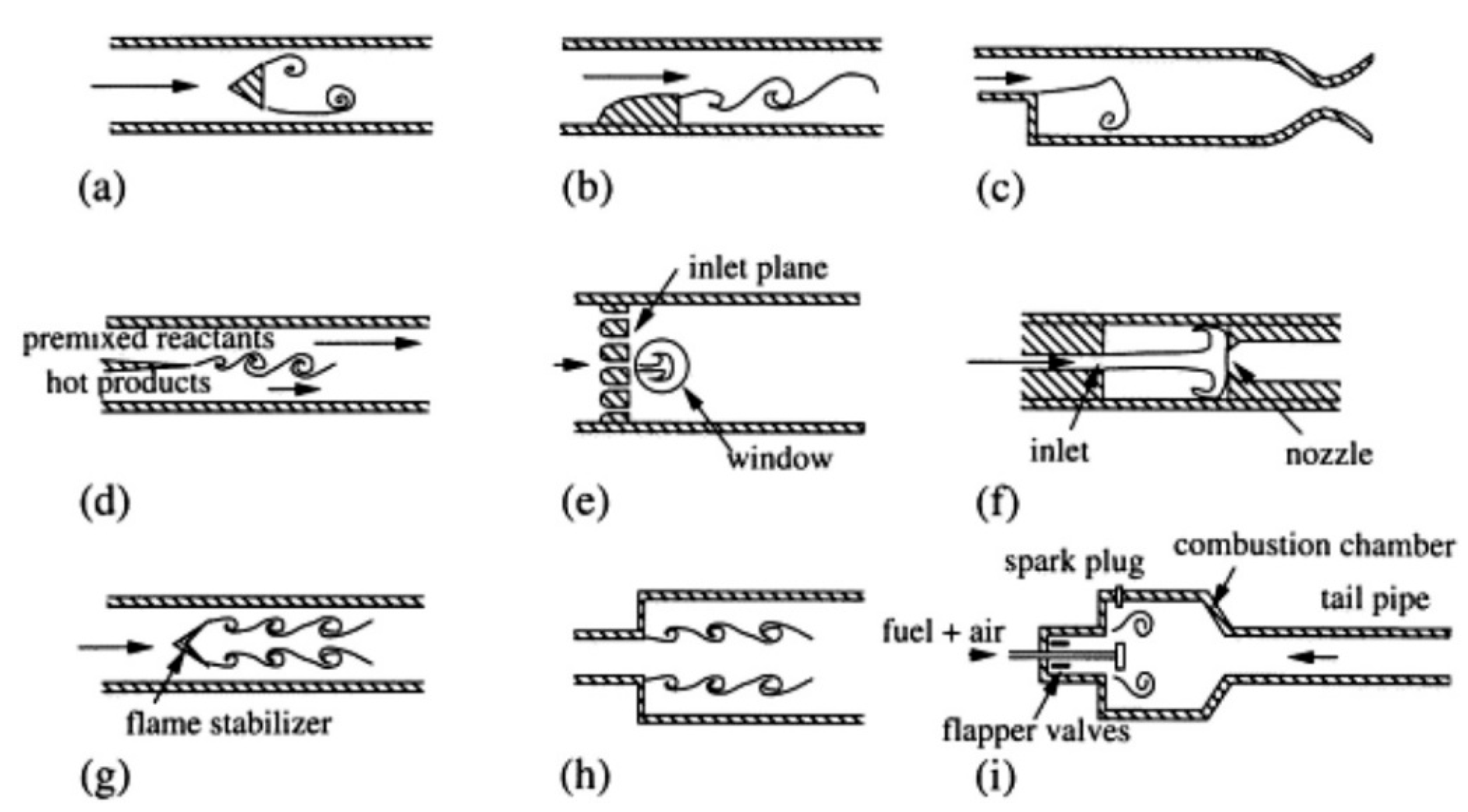
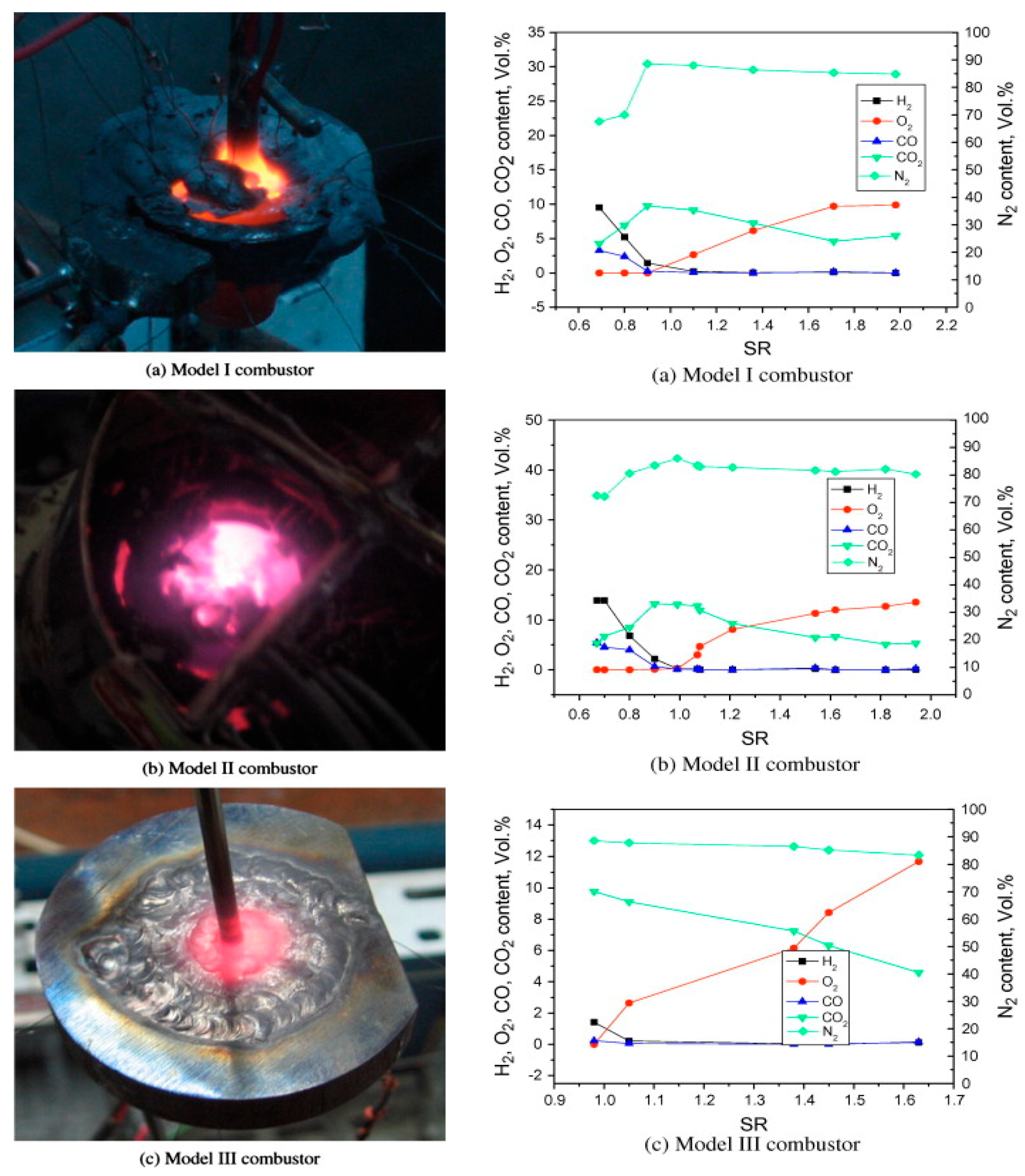
4.1. Micro Scale Combustion Systems

The combustion characteristics in micro- and mesoscale combustors have been investigated through various experimental studies with different combustor configurations. The development of advanced combustion engines for UAVs is challenging due to their operational requirements, and there are practical aspects of these studies that make them distinct from conventional combustors, including thrust generation, TSFC, engine power density, safety aspects, and the use of jet fuels. Recent developments in flame stabilization have focused on using different geometrical modifications, catalysts, heat recirculation, counter flows, swirlers, and porous media flows in conventional combustors. Investigations were conducted using hydrogen/air, methane/air, and hydrocarbon/air mixtures [24,37,73,91,92,93,94,95,96,97,98,99]. Several studies with can-type combustors for micro gas turbines have also been reported, such as one by Sadatakhavi et al. that investigated flame behavior and predicted temperature distribution using liquid fuels [85,86,100]. The experimental setup with Amirkabir’s micro gas turbine combustor is illustrated in Figure 4 with details of a swirl injector. The swirler with a swirl number of 0.86 was used to direct the flow downstream along with kerosene fuel spray using a hollow swirl injector with a spray angle of 60° [100]. Liquid fuel combustion requires a detailed understanding of flow behavior in the inner recirculation zones that support the atomization and vaporization processes.
Sadatakhavi et al. conducted experimental and numerical investigations on the characteristics of reactive and non-reactive flows [85,86,100]. They identified the atomization process in the recirculation zone by supplying fuel and air through a swirler, and Figure 5 shows the droplet profiles in the inner recirculation zone (IRZ) under both reactive and non-reactive conditions. The Sauter mean diameter (SMD) profile indicates a reduction in fuel droplet diameter due to high turbulent kinetic energy in the flow, which generates recirculation zones around the liner walls and promotes the vaporization of fuel droplets. Experimental studies have mapped the flame zones using temperature measurements in various zones of the combustor. The swirl angle enhances the efficiency of the combustor through improved evaporation in the IRZ. Similar studies have been conducted by Liu et al. with variations in swirl blade angles and combustion stage nozzles, which influenced combustion characteristics such as efficiency, stability, ignition, and temperature fluctuations [37]. Experimental studies on dry low emission (DLE)-type lean premixed combustion systems have shown that changes in swirl angles and flow characteristics improve fuel and air mixing uniformity, affecting vaporization in the IRZ and combustion performance [101]. Sahota et al. performed a study on controlled swirl flow with backward-facing steps and found that flammability limits increase significantly with incoming flow [102].
Swirl was found to have an influence on the temperature profile, improving the temperature distribution for all equivalence ratios compared to no swirl. The flame position remained unchanged despite changes in equivalence ratio, but its effects were evident in an active swirl reformer [102]. Studies on can-type micro combustors with kerosene, jet fuels, hydrogen, and methane focused on flame stabilization, enhancing blow-off limits at higher velocities, and injection strategies. The fuel injection angle significantly impacted flame structure when tested with different swirl angles, and the use of a high swirl number favored flame stability [65,103]. Developing efficient atomizers to increase fuel/air mixing for lean combustion conditions is of special interest. Injection length also had a significant effect on the combustion process. Figure 6 illustrates the concept of an upward swirl combustor with lean combustion limits and temperature distributions in the primary combustion zone.
The swirl number is an important parameter for evaluating the combustion characteristics of can combustors. Kankashvar et al. [86] investigated the effect of swirl angle on flame structure and combustion characteristics using an 18-blade swirler and cone atomizer. They tested this configuration with different spray cone angles (45°, 60°, and 80°). The swirl number can be calculated using the following equation:
S w i r l   N u m b e r = 2 3 1 D h u b D s w 3 / 1 D h u b D s w 2 tan θ ,
where D h u b indicates the swirler hub diameter, D s w the swirler diameter, and θ swirler vane angle.
Furuhata et al. introduced the concept of upward swirl and conducted experimental studies using kerosene to understand the effects of swirl angle under high swirl number conditions as shown in Figure 6 [104]. In this type of combustor, the swirler is placed between the primary and secondary zones to enhance mixing and recirculation. A parametric study with four combustion liner lengths, Z p , was performed to optimize the primary zone for efficient combustion under lean conditions, with an optimized Z p of 109 mm showing better performance. The location of the flame is crucial for evaluating the condition of combustion with the swirler and the optimized primary zone. The swirler vane angle and throat diameter were fixed for the experimental studies to estimate lean combustion limits, and recirculating burned gas in the primary zone significantly affected emissions by enhancing the inlet conditions of the fuel/air mixture. Temperature distribution inside the combustion chamber is shown in Figure 7 for different spray cone angles, with the temperature profile at different injection angles reflecting the importance of atomization angle and novel atomizer selection. Lower atomization angles enhance fuel-air mixing in the center of the combustor, thereby inducing high flame temperatures. These studies highlight the importance of developing efficient atomizers and swirlers to enhance the combustion characteristics of can-type micro combustors.
The development of efficient micro combustors has attracted significant attention from researchers, and key findings are summarized in Table 3. Various configurations with flame stabilization mechanisms have been tested using different fuel mixtures, making them suitable for different applications. Bluff-body flame stabilization studies have been conducted on various micro combustor configurations, and the flames can be stabilized at high velocities due to their downstream blunt shape, which creates a wake of eddies behind the object [105]. The shape and position of the bluff body and inlet velocities have significant impacts on the flame structure, improving the blow-off limits at high velocities [16,106,107,108].
Wan et al. tested different bluff-body configurations in a planar micro channel with lean premixed hydrogen/air mixtures and observed that the high-temperature zone shifted gradually with increasing velocity, and the flame was stabilized behind the bluff body [18]. Figure 8 shows the direct images of the flame at different inlet velocities of 15, 23, and 40 m/s. The bluff body established stable combustion in the narrow channels with higher heat release and chemical reaction rates. At moderate inlet velocities, there was a gradual rise in the exhaust gas temperature due to the fuel/air mixture having enough time to mix and burn completely. However, at higher inlet velocities, the exhaust gas temperature started decreasing due to incomplete combustion. Heat loss played an important role in determining combustion efficiency and exhaust gas temperature due to the large surface area to volume ratio of the micro combustors. Fan et al. investigated the effect of combustor material on the blow-off limits and flame stabilization in bluff-body narrow channels and showed that a quartz combustor exhibited better performance than stainless steel and SiC ones due to its low thermal conductivity, which favored the blow-off limit due to weak flame stretching effects [79].
The thermal conductivities of stainless steel and SiC are greater than that of quartz, resulting in a more efficient transfer of heat. Consequently, the temperature profiles of walls made from stainless steel or SiC are significantly different from those made from quartz, mainly due to the increased heat transfer at the upstream location [79]. Thermal management is also a crucial aspect of addressing the flame stability issues that arise in micro combustors and micro thermophotovoltaic applications. Tang et al. conducted experimental studies on a propane/air heat recirculation combustor that utilized symmetrical baffles and evaluated its performance [109]. To differentiate between the inlet and burning zones, they developed an experimental model featuring two symmetrical baffles, which enhanced preheating of the cold flow and improved combustion. They observed that the equivalence ratio and baffle length had significant effects on both the heat recirculation and combustion process. Specifically, longer baffle lengths resulted in greater heat loss due to increased surface area; nevertheless, this design with longer baffles proved advantageous in terms of recirculation and mixing of the incoming propane/air mixture.
Numerous methods have been proposed to achieve combined flame stabilization and heat recirculation in micro combustors, including the use of backward-facing step, central rod, porous media flows, wall cavities, bluff body, swirl, orthotropic wall, and catalyst [15,17,18,26,93,105,110,111,112,113,114,115,116]. To evaluate the combustion performance, various studies have been conducted on these configurations at different velocities and equivalence ratios. For example, a study on flame stabilization with bluff body and wall cavity has shown significant improvement in combustion efficiency [13]. Kang et al. investigated the flame stability limits and thermal performance of a parallel plate combustor with orthotropic wall made of pyrolytic graphite, which exhibits a high velocity limit due to improved temperature distribution on the plate [24]. Additionally, several experimental studies have indicated that controlling flame position with bluff bodies and using combined flame stabilization methods with backward-step channels favor heat recirculation. When combined with bluff bodies and wall cavities, these methods further improve thermal efficiency by anchoring the flame behind the bluff body and recirculating it in the backward step [117].

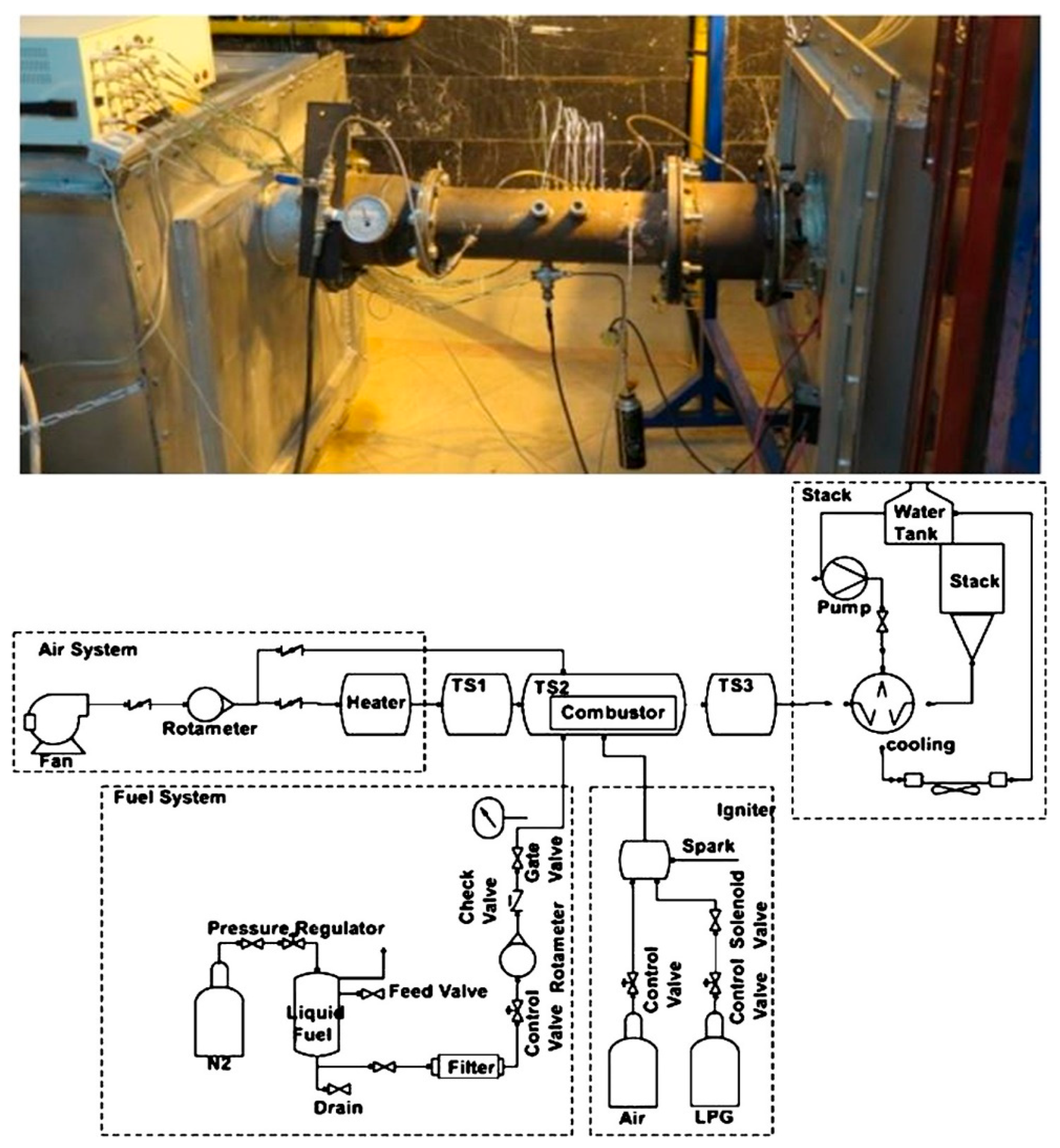
4.2. Mesoscale Combustion Systems

Small-scale combustion systems have been modified and transformed into micro- and mesoscale combustors with varying physical length, quenching diameter, and device scale. The microscale combustors span from 1 to 1000 μm, while the mesoscale combustors range from 1 to 10 mm and have been developed using MEMS technologies to power small applications [7]. Mesoscale combustors are used in various applications, such as rotary engines, Swiss-roll combustors, thrusters, and micro aerial vehicles. They are particularly used to power micro aerial vehicles that require efficient mesoscale combustors, which are included in several different engines, such as Stirling, Wankel, rotating piston, scaled gas turbine, and conventional spark ignition and compression ignition engines. Mesoscale combustors are more commonly used as low-impulse thrusters in the range of approximately 1 mN to 1000 mN [7].
In small-scale combustion systems, a major challenge is achieving stable combustion and efficient thermal management while igniting the propellant. To address combustion instabilities, wall heat transfer, and acoustic instabilities in mesoscale systems, numerous novel designs have been developed. Experimental and numerical studies have focused on examining flammability limits, combustion characteristics, and heat losses. One such design modification is the Swiss-roll combustor, which has been introduced in Stirling engines to enhance their performance for powering aerial vehicles and generating power. The addition of catalytic beds to the Swiss-roll combustor can also help to lower ignition temperature and increase combustion efficiency [69]. Mesoscale burners with various configurations are also being evaluated to power-scaled gas turbine engines. These changes include the incorporation of new injection strategies, swirlers, and combined flame stabilization technologies that work with hydrogen/air, jet fuel, and aviation gasoline. In addition, miniature Wankel rotary engines have been developed as mesoscale engines by incorporating new cooling technologies that can operate with multiple fuels, such as gasoline, JP-5, JP-8, and Jet-A1.
The Swiss-roll combustor, initially proposed by Lloyd and Weinberg as a burner of low-heat content, has been shown to be effective even with low-grade fuels [20]. At first, researchers sought to enhance the performance of the Swiss-roll combustor by incorporating radiation shields coated with strips around the spiral. They tested these shields at various surface temperatures and observed an increase in power density of 150 W/m2. Subsequent studies have concentrated on improving the design to achieve flame stabilization through heat recirculation [31,69,118,119]. Experimental studies by Zhong et al. on a premixed methane/air Swiss-roll combustor with three double spiral configurations of varying channel dimensions have shown stable combustion with methane/air [118]. The combustor, shown in Figure 9, exhibits an incandescent region, with combustion occurring at the center due to the narrow channel size, which preheats the mixture, resulting in high temperatures and stable flames. Gas chromatography analysis was used to determine combustion efficiency, and the results indicated incomplete combustion with H2 and CO. It was found that the flammable ranges are significantly extended, and thermal insulation plays a crucial role in achieving stable combustion with a methane flow rate of 2.0 mg/s and a temperature of 1100 K at the center [118].
In order to improve combustion performance, a proposal was made to use distributed mesoscale arrays combined with flame stabilization by a bluff body and tangential inlet flow swirl. Various fuel mixtures were evaluated for array combustors in mesoscale combustors to assess their performance [26,120,121,122,123,124,125,126,127,128]. Rajasegar et al. introduced mesoscale combustion arrays with an estimated combustion efficiency of 98% for lean mixtures [124]. These mesoscale burners are arranged in an array with premixed fuel/air mixture inlets separated by a bluff body and tangential inlet to produce swirl. The combined flame stabilization mechanism helps to address flame oscillations and extend the blow-off limits in the arrays. The detailed configuration and the lean blow-off limits are illustrated in Figure 10. This configuration enhances fuel/air mixing, which ultimately reduces the length scale of the combustor. Experimental studies have been conducted on different sets of burner arrangements using OH-PLIF, chromatography-mass spectrometry, and dynamic mode decomposition to analyze flame interactions [26,125]. OH-PLIF can be used to examine flame shapes, which can be clearly seen in the processed image. The shape of the flame is significantly affected by the equivalence ratio and inlet velocity. It has been observed that, for fuel-rich mixtures, merged flames are produced at low Reynolds numbers, while for lean mixtures, a V- or an M-shaped flame is produced.
The transition from a V-shaped to an M-shaped flame is also observed with increasing equivalence ratio and inlet velocities [126], where the geometry of the burner plays a crucial role due to wall interactions at the bluff body and sudden expansion in the swirler. It is important to investigate the optimal inlet velocities for lean mixtures to achieve a stable flame and to note that the flame lifts off when the fuel flow rate is reduced at a constant air flow rate. A full-scale burner can sustain the flame at an equivalence ratio of less than 0.7, which corresponds to similar behavior in a single burner [125]. Investigating the performance of aviation fuels is significant to develop engines for different classes of aerial vehicles. Combustion stability was compared between jet fuels and conventional petroleum-based fuels for understanding thermal quenching, extinction mechanisms, and operating conditions. Choi et al. evaluated the performance of hydrocarbon fuels in small-scale systems using jet A and methane at an equivalence ratio of 0.8 in a mesoscale swirl-stabilized combustor array to improve flame stability and combustion length scale [26]. They showed that jet A is less stable than methane at lean blow-off limits, as seen in Figure 11, where the jet A flame exhibits more fluctuation with high-mode energy content compared to the methane flame.
Various types of porous media, including ceramic fiber, packed bed, SiC foam, folded stainless steel mesh, graphite fibers, sintered powder, and nickel foam, have been receiving significant attention to improve combustion characteristics [93,112,119,129,130]. Ning et al. investigated the effects of fibrous porous media on ignition distance, flammable range, and combustor performance in a Y-shaped combustor [129]. The use of porous media extended the flammability range to 0.16–0.50 m/s, while the burner without porous media had a range of 0.23–0.34 m/s. Kang et al. developed a combined porous media to enhance heat transfer characteristics in mesoscale thermophotovoltaic power generators [130]. The results demonstrated that the use of porous foam effectively improves combustor performance. In addition, Chen et al. studied the effects of porous media on flame stability and thermal performance in mesoscale burners fueled with ethanol [112]. In their experimental studies, three different configurations were tested to understand the effect of porous media with 10 pores per inch (ppi) nickel foam applied at the combustion section. The results showed that blue flames entered the porous media region, and the stable operating range of the porous media was depicted at different air preheat temperatures, as shown in Figure 12. Furthermore, two different materials of zirconia foam and nickel foam were applied at the combustion section of the mesoscale burner with liquid ethanol premixed flames to estimate the radiation output. The flame exhibited an oscillatory pattern with decreasing flow rate due to the overheating of the fuel nozzle. Figure 13 illustrates the effect of flow rate on the flame shape, showing a quasi-symmetrical flame with an inner cone and external diffusion flames readily observed with an increase in flow rate to 270 mL/min [112]. The use of porous media was found to enhance flame speed and significantly increase the radiant intensity of the mesoscale burner.
Various types of engines, such as microthrusters, rocket chips, and staged thrusters, have been developed for different operating conditions. Among them, mesoscale vortex chambers are widely used in power and propulsion applications. To achieve efficient fuel/oxidizer mixing in these combustors, the inlets are designed to have tangential oxidizer injection and perpendicular fuel injection [30,131]. Wu et al. conducted experimental studies on different mesoscale vortex stabilized combustor configurations with varying volumes and diameters [30]. Figure 14 describes the flame characteristics of the propane/air flame in the 124 mm3 combustor with an equivalence ratio of 0.8 and the methane/oxygen-enriched air flame in the 49.1 mm3 combustor with an equivalence ratio of 0.3. The whirling flame is observed to rotate around the luminous flame zone, but achieving stable combustion is challenging due to strong viscous loss as the chamber volume decreases. Advanced thermal recuperation has been developed for the vortex chambers and tested with hydrocarbon fuels under non-premixed conditions. Hosseini et al. investigated the combustion characteristics using two different configurations with and without thermal recuperation [80]. Thermal recuperation improves the flame stability of lean mixtures at high velocities and significantly impacts the mean wall temperature of the combustors at high equivalence ratio and high Reynolds numbers. The development of miniature thrusters for space applications with bi-propellants and solid propellants was also investigated, and their design was modified to accommodate the low volume and the mode of combustion. The electrolytic microthruster was found to be a promising option for smaller volumes ranging from 200 to 600 μm. These thrusters were developed with three layers for electrolytic reaction of a hydroxylammonium nitrate (HAN) [7]. Figure 14 depicts a three-layer configuration developed with ceramics for HAN-based propellant and combustor volume of 0.82 mm3, with the ceramic offering high-temperature strength and shock resistance [132].
The application of porous media to enhance combustor performance in thermoelectric and photovoltaic applications is a well-established technique. These developments offer improved combustion characteristics and thermal management in micro- and mesoscale channels, making them suitable for use in miniature UAV engines. Various configurations have been tested to understand the impact of the position of porous media in the combustor from the inlet to the combustor zone, and the performance of the combustor with methane/air and hydrogen/air has been extensively investigated [3,93,130,133,134,135]. Li et al. performed experiments on a 1 mm channel operating at low velocities with hydrogen/air premixed flames to investigate the effect of porous media on heat transfer and system efficiency. The performance of the system is influenced by the position of the porous media, and three different configurations have been evaluated: 4.5, 9.0, and 13.5 mm, each with a fixed equivalence ratio of 0.8. At higher inlet velocities, the 9 mm region, located in the middle of the combustor, exhibits higher combustion efficiency [93]. Figure 15 illustrates the variation in the wall temperature as a function of the equivalence ratio and the inlet velocities. When the porous media exist between 8 and 11 mm, with an equivalence ratio of 0.8 to 1.0 for 3 m/s inlet velocity, the combustor performs the best. Similar performance is also observed for 2 m/s, and it is recommended to use optimized porous media in combustors to achieve better efficiency under lean premixed conditions.

5. Numerical Studies on Micro Combustors

High-performance computing (HPC) resources are available for numerical investigations of various micro combustor configurations. Combustion models in commercial, in-house, and open-source CFD solvers can be used to conduct reactive flow simulations, which aid in understanding flame stabilization. To configure existing micro combustors for specific applications, a detailed investigation of their performance is required. Flame stabilization studies for different configurations can be simulated using direct numerical simulation (DNS), large eddy simulation (LES), and Reynolds-averaged Navier–Stokes equation (RANS) simulation to comprehend the influence of turbulence on the combustion process. Different fuel compositions, such as lean mixtures of hydrogen/air, methane/air, propane/air, and jet fuel/air, are used in micro combustors. The computational studies utilize well-developed reaction mechanisms specific to each fuel set. Turbulent premixed flames provide comprehensive insights regarding flame stabilization and vortex shedding into the flow field. The use of bluff bodies and swirlers induces flow fluctuations and recirculation zones behind them. Direct numerical simulations offer realistic flow configurations, which enhance understanding of micro combustion. In micro combustors with bluff bodies, strong eddies are generated, leading to local quenching and resignation [136]. A comprehension of flame/turbulence interaction is crucial to address combustion instabilities and flame regrowth in the upstream of the channel.
Various numerical simulations have been conducted to study the behavior of flames in different configurations, with a focus on resolving turbulent reacting flows. Lee et al. performed DNSs of hydrogen/air flames in a meso channel with a bluff body to understand the flame dynamics near the blow-off limit [16]. This study employed a multicomponent-reactive Navier–Stokes equations with 9 species and 19 reactions and demonstrated the complex sequence of events that occur during local extinction and recovery of the flame, including the regrowth of bulk flame by flame segments attached behind the bluff body. Figure 16 shows instantaneous snapshots at local extinction and isocontours of Y H 2 O / Y H 2 O , max for U = 20.5 m/s. A new instability mode was observed at an inflow velocity of 20 m/s, leading to local extinction and recovery. Tanaka et al. investigated the effects of swirl and combustion on premixed flame structure and heat transfer characteristics in a micro gas turbine combustor, using VODE solver with compact finite difference filters [137]. The study analyzed the hydrodynamic behavior and flame structure for cold and reactive flows with two different swirl numbers at 15 m/s and 30 m/s. The micro combustor design was also studied for heat recirculation and heat loss from the walls, and the DNS studies considered heat flux on the walls to estimate heat transfer in the combustor. Figure 17 shows the heat flux distribution for two cases with different swirl numbers of 0.6 and 1.2. Figure 18 depicts the correlation between the flame and flow structure at high frequencies. It presents a time-series graph of pressure fluctuations at the inlet, specifically for the low swirl number case with perturbations. The figure highlights typical pressure conditions, including (a) downturn, (b) saddle point, (c) local minimum, and (d) upturn. For each of these typical pressure conditions, the figure provides volume rendering of the instantaneous heat release rate and instantaneous streamlines [137]. The results indicated that heat flux on the walls depended on oscillations at these swirl numbers. The high-fidelity DNS studies demonstrated the multiscale phenomena of micro combustors, including the characteristics of flame structure and heat transfer to the walls.
DNS studies require significant computational resources to accurately resolve all spatial and temporal turbulence scales. Due to this limitation and the complexity of the problem, many numerical studies have been conducted using LES and RANS by modelling turbulent reacting flows. For instance, Tyliszczak et al. utilized RANS with the k ε turbulence model and LES with the wall adapting local eddy (WALE) viscosity subgrade model to investigate combustion processes in a medium-scale gas turbine [138]. They modelled the combustion process using a steady laminar framelet model with Smooke mechanism, including 16 species and 25 elementary reactions. The researchers optimized the fuel injection location using three different injection methods to alter the multipoint fuel injection, which affected the flow dynamics and temperature distribution. In another study, Benard et al. conducted a high-fidelity LES of a hydrogen-enriched methane/air flame in a quasi-cubic mesoscale whirl flow combustor using the finite volume code, YALES2, which can solve low Mach number flows with unstructured complex mesh [139]. They modelled the chemical reactions using the Arrhenius chemical kinetics approach, and the use of whirl flow topology enhanced the mixing and improved the burner performance.
Sadatakhavi et al. conducted numerical studies of a can-type micro combustor with kerosene liquid fuel using RANS with the k ε . RNG turbulence model to simulate spray combustion with a high-swirl Eulerian–Lagrangian formulation [85]. They adopted the eddy dissipation concept (EDC) model to understand the importance of chemical kinetics with 12 species and 10 elementary reactions in turbulent flows. The combustion characteristics are shown in Figure 19 and Figure 20, which represent the inner recirculation zone, intermediate zone temperature, mass fraction, and the relationship between the temperature and combustion characteristics. The inner recirculation zone enhances the mixing through swirl-like configurations and becomes effective in evaporating fuel, while the combustion becomes efficient due to the recirculation zone around the linear wall.
In their investigation into flame stabilization, Jha et al. explored several different factors, ultimately determining that using a bluff body is one of the most effective methods to stabilize flames [13]. The study was focused on optimizing geometry-based parameters to gain a better understanding of how to stabilize flames in narrow channels. By generating a recirculation zone behind it, a bluff body can transfer thermal energy to upcoming fuel-air mixtures, helping with ignition. This recirculation zone can also increase residence time, which in turn extends and stabilizes the flame in the anchor zone. To test this theory, Jha et al. conducted a numerical study of nine different L / D ratios and optimized channel dimensions by examining blow-off limits. Bluff bodies with various shapes and configurations were placed at successive positions, the velocity and temperature profiles of nine different bluff body configurations are shown in Figure 21. The researchers found that the wall blade bluff body demonstrated superior performance under lean hydrogen/air premixed conditions. The researchers used RANS with the k ε turbulence model to conduct detailed studies on cases with three different velocities and a constant equivalence ratio of 0.5. Through geometrical modifications, performance was improved by a factor of two. In addition, the wall blade bluff body had the lowest exhaust gas temperature in all conditions, suggesting that the combustor was able to use most of the thermal energy and improve overall performance.
Taywade et al. and Aravind et al. proposed a three-step micro combustor with an outer cap that can improve flammability limits through heat and flow recirculation [115]. Figure 22 shows a schematic of a disc combustor with an annular step, featuring two inlets: one with a radial preheating channel for the air inlet and the other with a mixed channel designed to prevent flame flashback. Numerical studies were conducted on a quartz-glass double-disc micro combustor using a methane/air mixture with the DRM-19 mechanism (21 species and 84 reactions). The annular step created a recirculation zone, anchoring the flame upstream of the combustion chamber. The intake mixture was preheated by the recirculation zone, resulting in higher flame speeds. The double disc configuration was later modified to a miniature double-layer disc combustor with porous media and Swiss-roll pre-heated channel [119], which improved thermal performance and reduced anomalous blow-off limits by decreasing heat recirculation. In addition, Mehra et al. proposed a six-wafer combustion system for a silicon micro gas turbine engine, which exhibited stable combustion for high-temperature hydrogen/air mixtures [40].
The small size of submillimeter scale combustors presents a challenging issue in terms of heat recirculation, which can lead to thermal quenching. To address this problem, numerous novel designs have been proposed for mesoscale combustors. One such design is the Swiss-roll combustor, which utilizes heat recirculation from burned gas and preheating via spiral-shaped inlet channels [31]. Fan et al. investigated a Swiss-roll combustor with bluff bodies for steel, quartz, and SiC combustors featuring rectangular spiral patterns as shown in Figure 23. Numerical studies were conducted to assess various configurations. Due to the narrow channel diameter and low inlet velocities, low Reynolds numbers were observed, and turbulence had a minimal effect on combustion performance. However, improvements are necessary to operate these channels under lean premixed conditions.
A Swiss-roll combustor with flow recirculation channels and a 2.5 mm side length configuration was studied using a three-dimensional model. The use of the standard k ε turbulence model and SIMPLE algorithm facilitated the coupling of pressure and velocity, and surface radiation effects were considered to calculate wall heat loss using the discrete ordinate method (DOM). Numerical studies revealed that blow-off limits were extended by 10 m/s with a wedge-shaped bluff body [19]. The Swiss-roll combustor was further modified into a double-layer disc combustor with porous media to enhance thermal performance and extend blow-off limits for methane/hydrogen/air mixtures. The fresh mixtures were preheated in the Swiss-roll configuration, and metal foam in the combustion zone supported additional preheating of unburned mixtures [119]. In addition, Wang et al. investigated a divergent channel porous burner for ultra-low calorific gas, which increased heat recovery efficiency by 18% for minimum inlet gas temperatures [140].
Small-scale power generation applications benefit from micro-step combustors, which offer superior flame stabilization. To operate combustors at high velocities and enhance blow-off limits, modifications have been proposed, such as changing the inlet configuration and using helical fins [15,113]. The use of helical fins has been found to improve combustion performance with high mass flow rates. Zheng et al. conducted numerical simulations to study the effect of helical fins on the combustion performance in a micro step combustor [72]. The swirl induced by the helical fins enhanced mixing and improved combustion efficiency due to radiant energy conversion. The simulations resolved velocity and pressure coupling as well as conjugate fluid-solid heat transfer effects. Figure 24 illustrates a schematic of the combustor with helical fins and the ignition process of the helical fin anchored flame at V in = 34   m / s . The use of helical fins improved flame anchoring position and blockage effects at higher inlet velocities compared to simple step combustors. Similar studies were conducted with helical fins in different micro combustor configurations. The studies have shown that optimized fin positioning with a high swirl number improves the thermal performance and burning characteristics of different fuels [72,141,142,143].
Can-type combustors are commonly used in micro gas turbines due to their compact design. However, their performance can be improved by introducing baffles to the combustor. Suzuki et al. proposed a design with baffle plates that include a central fuel nozzle and multiple holes for air injection. Numerous studies have been conducted on the impact of these baffles on various combustion characteristics, such as heat transfer, fuel-air mixing, turbulent reactive flows, flame stability, and flow characteristics [144,145,146,147,148]. Results show that introducing baffle plates can significantly improve flow mixing and flame structure in the can combustors. Overall, the use of baffles enhanced flow mixing and combustion characteristics, leading to improved performance of the micro can combustor. The dimensions and shape of the baffle plates were optimized to achieve better mixing in the central region [144]. Woodfield et al. conducted numerical studies on multiple confined jets in a micro can combustor and found that dimensional modifications to the baffle plates improved performance compared to co-axial jets [146]. Yahagi et al. studied the flow structure and flame stability in a micro can combustor with a baffle plate and found that the plate enhanced flow recirculation and mixing, resulting in better combustion conditions [147].
The shape of the baffle inlet holes also played an important role in the distribution of streamwise velocity along the central line and non-circular holes helped the fast decay of the streamwise velocity [144]. It has been shown that triangular holes experienced early development of the recirculation region at the fuel jet. The axial distribution of temperature for three air inlet baffle shapes are shown in Figure 25. The central recirculation zone has shown impact on the temperature distribution; in the case of triangular holes, the rise has been from x / D f = 2 , whereas the square and circular holes have shown flame formation in the forward region. This effect can be seen due to the delay in activation of the reaction, which was caused by the delay in the formation of a central recirculation zone with the air fuel jets. A 3-D numerical study helps in understanding the flame lengths in different baffle shapes; however, the diameter of the combustor also has a significant impact on the flame structure [144]. The use of baffles improves combustion characteristics and helps to stabilize the flame in combustors.
Kim et al. investigated a micro can combustor that incorporated a baffle plate consisting of seven holes for CH4/air mixture [148]. They used the eddy dissipation model (EDM) and framelet model to analyze the system. The baffle design included six annular air inlets of varying shapes, such as triangles, circles, square holes, and a fuel nozzle at the center. The turbulent reacting flows were solved using three turbulent models: standard k ε (SKE), Reynolds stress model (RSM) and shear stress transport k ω (SST k ω ), along with GRI-MECH 3.0. The results showed that the baffle plate configuration with different hole shapes, along with the central fuel nozzle, improved flow mixing and combustion characteristics. The mixture fractions obtained from the framelet model with 16 species and 41-step reaction mechanism were compared with Brookes and Moss experimental data and the results obtained from the EDM model. The profiles of streamwise velocity, mixing fraction, and temperature along the centerline of the jet flow were shown in Figure 26. The framelet model performed better than the EDM model. They also observed axis-switching flow structures for air jets past the baffle plate with the square and triangular holes [148]. The use of baffle holes as inlets develops jet flow, and axis switching has an impact on spreading rate and flow mixing. They recommended using 30° rotated square holes and 15° rotated triangular holes to improve uniformity of the combustor. Based on the mixing length, 45° for square and 60° for triangular holes were recommended to improve combustion performance and thermal characteristics.
The heat transfer in micro combustors is enhanced by embedding porous media, and the selection of combustor shape is important for both flame stabilization and heat recirculation. Heat recirculation using porous media is particularly useful for micro aerial vehicles, grouping array thrusters, and micro spacecraft that operate in the 1–10 mN thrust range for satellite altitude control and orbital insertion [149,150]. Experimental and numerical studies have investigated the use of porous media materials with strong thermal conductivity, such as stainless steel, ceramic, quartz, alumina, cordierite, platinum, and silicon carbide coated with platinum, and proposed various configurations with cylindrical tubes, rectangular slots, and radial microchannels [3,93,134,149].
Yan et al. used computational fluid dynamics to investigate a U-shaped micro combustor with a peripheral recirculating channel and a central channel embedded with porous media for heat recirculation. The study employed the RANS method with the k ε turbulence model and a 39-step reaction mechanism for methane oxidation. The effect of porous media material and thickness on the flame stability limits of methane/air mixture was studied, and it was found that using porous media materials such as Al2O3, SiC, and ZrO2 improves flame stability and enhances heat transfer [149]. Figure 27 shows the U-shaped micro combustor with a peripheral recirculating channel and a central channel embedded with porous media. The U-shaped micro combustor had an inlet velocity of 20 m/s and an equivalence ratio of 0.5, and the thickness of the porous media was varied from 5 to 25 mm using Al2O3-based ceramics. The results showed that the use of porous media improved effective heat transfer to the baffle inner surface, and the central line temperatures increased by 25 mm in the thickness of the porous media. Among the three configurations tested, the SiC combustor exhibited higher baffle temperatures than its counterparts due to its high thermal conductivity; however, this effect was limited by its low operating temperatures [149]. Therefore, the use of porous media for flame stabilization can improve combustion characteristics in micro combustors with lean mixtures for a wide range of velocities.

6. Summary and Outlook

The use of combustion-based engines to power UAVs aims to enhance the endurance and payload capabilities of vehicles. Most modern UAVs designed to meet military and defense needs utilize hybrid engines that provide several advantages, including improved fuel efficiency, reduced emissions, and quieter operations. The cost of engines remains a significant factor in the adoption of hybrid engines for commercial UAVs. Therefore, to cater to the needs of commercial operations, there is ongoing research and development focused on a variety of technologies aimed at creating low-cost, efficient engines. The progress of these technologies is continuously reviewed to identify opportunities for further improvement. The development of innovative combustors with efficient flame stabilization and heat recirculation is essential. This is particularly important in small-scale combustors where flame instabilities can occur due to the low length scales involved. Most studies established a concurrent understanding on extending the blow-off limits through geometrical modifications or by changing the flow characteristics. Micro combustor flame stabilization is a technique used in the design of UAV engines to improve their combustion efficiency and stability. In this technique, a flame stabilization mechanism is used to enhance the flame-holding capability of the combustor, which ensures that the flame remains stable and does not extinguish. Different mechanisms, such as vortex generators, bluff bodies, and recirculation zones, have been employed for micro combustor flame stabilization in UAV engines. These mechanisms improve the residence time of the fuel and air mixture, leading to better mixing and more efficient combustion. They also create low-velocity regions, increasing the residence time of the fuel and air mixture in the combustor, which results in a more stable flame structure. Bluff-body flame stabilization is a technique that shows promise in improving the performance and reliability of micro-meso scale combustors by increasing the blow-off limits by two to three times.
Some more detailed studies are necessary to achieve improved combustion characteristics with the micro-meso scale engines. However, only limited literature is available for UAV combustors based on experimentally tested miniature engines. Most of the applications are developed for power generation, propulsion, and space applications. A large part of the work focused on scaling the engines from gas turbines, spark ignition, and compression ignition engines. Advancements in engine technology have also led to the development of new types of UAVs, including vertical takeoff and landing (VTOL) and hybrid airships, which have unique engine requirements. This review merits a first step in developing a framework for flame stabilization technologies for UAVs.

Author Contributions

G.V.: writing—original draft, visualization, funding acquisition. C.S.Y.: writing—reviewing and editing, supervision, project administration, funding acquisition. All authors have read and agreed to the published version of the manuscript.

Funding

This research received funding to support the research manpower as a visiting fellow from Science and Engineering Research Board (SERB-DST), Government of India (Grant No. SIR/2022/000224). C.S.Y. was supported by Basic Science Research Program through the National Research Foundation of Korea (NRF) funded by the Ministry of Science and ICT (NRF-2021R1A2C2005606).

Data Availability Statement

No new data were created or analyzed in this study. Data sharing is not applicable to this article.

Acknowledgments

The authors would like to acknowledge the financial support from science and Engineering Research Board (SERB-DST), government of India (Grant No. SIR/2022/000224). G.V. would like to thank University of Petroleum and Energy Studies, Dehradun, India. This research was also conducted in the frame of the collaboration with UPES, Dehradun. C.S.Y. was supported by Basic Science Research Program through the National Research Foundation of Korea (NRF) funded by the Ministry of Science and ICT (NRF-2021R1A2C2005606).

Conflicts of Interest

The authors declare that they have no known competing conflict of interest or personal relationships that could have appeared to influence the research. The funders had no role in the design of the study; in the collection, analyses, or interpretation of data; in the writing of the manuscript; or in the decision to publish the results.

References

  1. Shirsat, V.; Gupta, A. A review of progress in heat recirculating meso-scale combustors. Appl. Energy 2011, 88, 4294–4309. [Google Scholar] [CrossRef]
  2. Wan, J.; Fan, A. Recent progress in flame stabilization technologies for combustion-based micro energy and power systems. Fuel 2020, 286, 119391. [Google Scholar] [CrossRef]
  3. Jadhav, G.Z.; Gupta, K.K. Review of Effect of Meso Scale Combustor Wall Material, Catalytic Material, Porous Media on Flame Stabilization. In Proceedings of the IOP Conference Series: Materials Science and Engineering, Mumbai, India, 23–24 December 2019; Volume 810. [Google Scholar] [CrossRef]
  4. Chou, S.; Yang, W.; Chua, K.J.; Li, J.; Zhang, K. Development of micro power generators—A review. Appl. Energy 2011, 88, 1–16. [Google Scholar] [CrossRef]
  5. Yuasa, S.; Oshimi, K.; Nose, H.; Tennichi, Y. Concept and combustion characteristics of ultra-micro combustors with premixed flame. Proc. Combust. Inst. 2005, 30, 2455–2462. [Google Scholar] [CrossRef]
  6. Tan, D.; Ran, G.; Xie, G.; Wang, J.; Luo, J.; Huang, Y.; Cui, S.; Zhang, Z. Effect of Different Technologies on Performance Enhancement of the Micro-Combustor for the Micro Thermophotovoltaic Application: A Review. Energies 2021, 14, 6577. [Google Scholar] [CrossRef]
  7. Ju, Y.; Maruta, K. Microscale combustion: Technology development and fundamental research. Prog. Energy Combust. Sci. 2011, 37, 669–715. [Google Scholar] [CrossRef]
  8. Jejurkar, S.Y.; Mishra, D.P. Annular Microcombustor and Its Characterization. In Advances in Combustion Technology; CRC Press: Boca Raton, FL, USA, 2022; pp. 1–33. ISBN 9781000726060. [Google Scholar]
  9. Jiaqiang, E.; Mei, Y.; Feng, C.; Ding, J.; Cai, L.; Luo, B. A review of enhancing micro combustion to improve energy conversion performance in micro power system. Int. J. Hydrogen Energy 2022, 47, 22574–22601. [Google Scholar] [CrossRef]
  10. Jiaqiang, E.; Luo, B.; Han, D.; Chen, J.; Liao, G.; Zhang, F.; Ding, J. A comprehensive review on performance improvement of micro energy mechanical system: Heat transfer, micro combustion and energy conversion. Energy 2022, 239, 122509. [Google Scholar] [CrossRef]
  11. Maruta, K. Micro and mesoscale combustion. Proc. Combust. Inst. 2011, 33, 125–150. [Google Scholar] [CrossRef]
  12. Fernandez-Pello, A.C. Micropower generation using combustion: Issues and approaches. Proc. Combust. Inst. 2002, 29, 883–899. [Google Scholar] [CrossRef]
  13. Jha, V.; Velidi, G.; Emani, S. Optimization of flame stabilization methods in the premixed microcombustion of hydrogen–air mixture. Heat Transf. 2022, 51, 5896–5918. [Google Scholar] [CrossRef]
  14. Khandelwal, B.; Kumar, S. Experimental investigations on flame stabilization behavior in a diverging micro channel with premixed methane–air mixtures. Appl. Therm. Eng. 2010, 30, 2718–2723. [Google Scholar] [CrossRef]
  15. Malushte, M.; Kumar, S. Flame dynamics in a stepped micro-combustor for non-adiabatic wall conditions. Therm. Sci. Eng. Prog. 2019, 13, 100394. [Google Scholar] [CrossRef]
  16. Lee, B.J.; Yoo, C.S.; Im, H.G. Dynamics of bluff-body-stabilized premixed hydrogen/air flames in a narrow channel. Combust. Flame 2015, 162, 2602–2609. [Google Scholar] [CrossRef]
  17. Zhang, L.; Zhu, J.; Yan, Y.; Guo, H.; Yang, Z. Numerical investigation on the combustion characteristics of methane/air in a micro-combustor with a hollow hemispherical bluff body. Energy Convers. Manag. 2015, 94, 293–299. [Google Scholar] [CrossRef]
  18. Wan, J.; Fan, A.; Maruta, K.; Yao, H.; Liu, W. Experimental and numerical investigation on combustion characteristics of premixed hydrogen/air flame in a micro-combustor with a bluff body. Int. J. Hydrogen Energy 2012, 37, 19190–19197. [Google Scholar] [CrossRef]
  19. Fan, A.; Zhang, H.; Wan, J. Numerical investigation on flame blow-off limit of a novel microscale Swiss-roll combustor with a bluff-body. Energy 2017, 123, 252–259. [Google Scholar] [CrossRef]
  20. Lloyd, S.A.; Weinberg, F.J. A burner for mixtures of very low heat content. Nature 1974, 251, 47–49. [Google Scholar] [CrossRef]
  21. Li, J.-W.; Zhong, B.-J.; Wang, J.-H. Numerical Simulation of Micro Swiss-Roll Combustor. Ranshao Kexue Yu Jishu/J. Combust. Sci. Technol. 2008, 14, 533–539. [Google Scholar]
  22. Gürbüz, H.; Akçay, H.; Aldemir, M.; Akçay, I.H.; Topalcı, Ü. The effect of euro diesel-hydrogen dual fuel combustion on performance and environmental-economic indicators in a small UAV turbojet engine. Fuel 2021, 306, 121735. [Google Scholar] [CrossRef]
  23. Fleming, J.; Ng, W.; Ghamaty, S. Thermoelectric-Based Power System For UAV/MAV Applications. In Proceedings of the 1st UAV Conference, Portsmouth, VA, USA, 20–23 May 2002; American Institute of Aeronautics and Astronautics: Reston, VA, USA, 2002. [Google Scholar] [CrossRef]
  24. Kang, X.; Veeraragavan, A. Experimental investigation of flame stability limits of a mesoscale combustor with thermally orthotropic walls. Appl. Therm. Eng. 2015, 85, 234–242. [Google Scholar] [CrossRef]
  25. Kang, X. A Numerical Study on Enhanced Micro-Flame Stabilization Using Thermally Orthotropic Combustor Walls. In Proceedings of the 12th Asia-Pacific Conference on Combustion, ASPACC, Fukuoka, Japan, 1–5 July 2019. [Google Scholar]
  26. Choi, J.; Rajasegar, R.; Liu, Q.; Lee, T.; Yoo, J. Jet A Combustion in a Mesoscale Swirl-Stabilized Combustor Array. Energy Fuels 2021, 35, 10796–10804. [Google Scholar] [CrossRef]
  27. Landry-Blais, A.; Sivić, S.; Picard, M. Micro-Mixing Combustion for Highly Recuperated Gas Turbines: Effects of Inlet Temperature and Fuel Composition on Combustion Stability and NOx Emissions. J. Eng. Gas Turbines Power 2022, 144, 091014. [Google Scholar] [CrossRef]
  28. Wan, J.; Fan, A.; Liu, Y.; Yao, H.; Liu, W.; Gou, X.; Zhao, D. Experimental investigation and numerical analysis on flame stabilization of CH4/air mixture in a mesoscale channel with wall cavities. Combust. Flame 2014, 162, 1035–1045. [Google Scholar] [CrossRef]
  29. Shimokuri, D.; Taomoto, Y.; Matsumoto, R. Development of a powerful miniature power system with a meso-scale vortex combustor. Proc. Combust. Inst. 2017, 36, 4253–4260. [Google Scholar] [CrossRef]
  30. Wu, M.-H.; Wang, Y.; Yang, V.; Yetter, R.A. Combustion in meso-scale vortex chambers. Proc. Combust. Inst. 2007, 31, 3235–3242. [Google Scholar] [CrossRef]
  31. Kim, N.I.; Kato, S.; Kataoka, T.; Yokomori, T.; Maruyama, S.; Fujimori, T.; Maruta, K. Flame stabilization and emission of small Swiss-roll combustors as heaters. Combust. Flame 2005, 141, 229–240. [Google Scholar] [CrossRef]
  32. Vijayan, V.; Gupta, A. Flame dynamics of a meso-scale heat recirculating combustor. Appl. Energy 2010, 87, 3718–3728. [Google Scholar] [CrossRef]
  33. Waitz, I.A.; Gauba, G.; Tzeng, Y.-S. Combustors for Micro-Gas Turbine Engines. J. Fluids Eng. 1998, 120, 109–117. [Google Scholar] [CrossRef]
  34. Prade, B. Gas Turbine Operation and Combustion Performance Issues. In Modern Gas Turbine Systems: High Efficiency, Low Emission, Fuel Flexible Power Generation; Woodhead Publishing Series in Energy: Cambridge, UK, 2013; pp. 383–422, 423e. [Google Scholar] [CrossRef]
  35. Jeschke, P.; Penkner, A. A Novel Gas Generator Concept for Jet Engines Using a Rotating Combustion Chamber. J. Turbomach. 2015, 137, 071010. [Google Scholar] [CrossRef]
  36. Zelina, J.; Anderson, W.; Koch, P.; Shouse, D.T. Compact Combustion Systems Using a Combination of Trapped Vortex and High-G Combustor Technologies. In Proceedings of the Volume 3: Combustion, Fuels and Emissions, Parts A and B; ASMEDC: Berlin, Germany, 2008; pp. 1–9. [Google Scholar]
  37. Liu, Y.; Nikolaidis, T.; Madani, S.H.; Sarkandi, M.; Gamil, A.; Sainal, M.F.; Hosseini, S.V. Multi-Fidelity Combustor Design and Experimental Test for a Micro Gas Turbine System. Energies 2022, 15, 2342. [Google Scholar] [CrossRef]
  38. Liu, H.; Zeng, Z.; Guo, K. Numerical analysis on hydrogen swirl combustion and flow characteristics of a micro gas turbine combustor with axial air/fuel staged technology. Appl. Therm. Eng. 2023, 219, 119460. [Google Scholar] [CrossRef]
  39. Badum, L.; Leizeronok, B.; Cukurel, B. New Insights From Conceptual Design of an Additive Manufactured 300 W Micro Gas Turbine Towards UAV Applications. In Proceedings of the Volume 8: Industrial and Cogeneration; Manufacturing Materials and Metallurgy; Marine; Microturbines, Turbochargers, and Small Turbomachines; American Society of Mechanical Engineers: New York, NY, USA, 2020. [Google Scholar] [CrossRef]
  40. Mehra, A.; Zhang, X.; Ayon, A.; Waitz, I.; Schmidt, M.; Spadaccini, C. A six-wafer combustion system for a silicon micro gas turbine engine. J. Microelectromech. Syst. 2000, 9, 517–527. [Google Scholar] [CrossRef]
  41. Peck, J. Development of a Liquid-Fueled Micro-Combustor; Massachusetts Institute of Technology: Cambridge, MA, USA, 1976. [Google Scholar]
  42. Sonawane, U.; Mustafi, N.N. Design and Development of Small Engines for UAV Applications, Advanced Combustion Techniques and Engine Technologies for the Automotive Sector 2019; Springer: Singapore, 2019; pp. 231–246. [Google Scholar]
  43. SCANEAGLE. Available online: https://www.boeing.com/defense/autonomous-systems/scaneagle/index.page (accessed on 22 December 2022).
  44. Department of Defense (DoD) Domestic Aviation Operations UNMANNED AIRCRAFT SYSTEMS (UAS). Available online: https://dod.defense.gov/UAS/ (accessed on 22 December 2022).
  45. UA Army UAS Center of Excellance Eyes of the Army, U.S. Army Roadmap for UAS 2010–2035. Available online: https://irp.fas.org/program/collect/uas-army.pdf (accessed on 22 December 2022).
  46. Lieutenant Colonel Andre Haider a Comprehensive Approach to Countering Unmanned Aircraft Systems. Available online: https://www.japcc.org/chapters/c-uas-introduction/ (accessed on 22 December 2022).
  47. Naval Technology ScanEagle—Mini-UAV (Unmanned Aerial Vehicle). Available online: https://www.naval-technology.com/projects/scaneagle-uav/ (accessed on 23 December 2022).
  48. Nelson, J.R.; Dix, D.M. Development of Engines for Unmanned Air Vehicles: Some Factors to be Considered; Institute for Defense Analyses: Fort Belvoir, VA, USA, 2003. [Google Scholar]
  49. Perrut, M.; Caron, P.; Thomas, M.; Couret, A. High Temperature Materials for Aerospace Applications: Ni-Based Superalloys and γ-TiAl Alloys. Comptes Rendus Phys. 2019, 19, 657–671. [Google Scholar] [CrossRef]
  50. Rolls-Royce Proven Power. Available online: https://www.rolls-royce.com/products-and-services/defence/aerospace/uavs/ae-3007.aspx (accessed on 22 December 2022).
  51. U.S. Department of Defense (DoD) and Rolls-Royce plc. Rolls-Royce M250 Turboshaft. Available online: http://www.fi-powerweb.com/Engine/Rolls-Royce-M250.html (accessed on 22 December 2022).
  52. Daussault Aviation Unmanned Combat Air Vehicle (UCAV). Available online: https://www.dassault-aviation.com/en/defense/neuron/introduction/ (accessed on 22 December 2022).
  53. Pratt & Whitney Canada PW500 MTU Aero Engines. Available online: https://www.mtu.de/engines/commercial-aircraft-engines/business-jets/pw500/ (accessed on 22 December 2022).
  54. Rotax GmbH & Co KG ROTAX POWERTRAINS. Available online: https://www.rotax.com/en/products/rotax-powertrains/details/rotax-914-f-ul.html (accessed on 22 December 2022).
  55. Honeywell TPE331-10 TURBOPROP ENGINE. Available online: https://aerospace.honeywell.com/us/en/products-and-services/product/hardware-and-systems/engines/tpe331-turboprop-engine. (accessed on 22 December 2022).
  56. Barnhart, R.K.; Marshall, D.M.; Shappee, E.J. (Eds.) Introduction to Unmanned Aircraft Systems, 3rd ed.; CRC Press: Boca Raton, FL, USA, 2021; ISBN 9780429347498. [Google Scholar]
  57. General Atomics Unmanned Aircraft Systems and Sensors. Available online: https://www.ga.com/unmanned-aircraft-systems-and-sensors (accessed on 7 November 2022).
  58. MQ-1C GRAY EAGLE UNMANNED AIRCRAFT SYSTEM (UAS). Available online: https://asc.army.mil/web/portfo-lio-item/aviation_gray-eagle-uas/ (accessed on 7 November 2022).
  59. Boukoberine, M.N.; Zhou, Z.; Benbouzid, M. A critical review on unmanned aerial vehicles power supply and energy management: Solutions, strategies, and prospects. Appl. Energy 2019, 255, 113823. [Google Scholar] [CrossRef]
  60. The International Institute for strategic studies Defence Data to Drive Your Strategy Military Balance+. Available online: https://www.iiss.org/about-us (accessed on 20 December 2022).
  61. TECH-FAQ, U.S. Drones. Available online: https://www.tech-faq.com/us-drones.html (accessed on 22 December 2022).
  62. Army Technology Hunter RQ-5A/MQ-5B/C UAV. Available online: https://www.army-technology.com/pro-jects/hunter/ (accessed on 20 December 2022).
  63. Renard, P.-H.; Thévenin, D.; Rolon, J.; Candel, S. Dynamics of flame/vortex interactions. Prog. Energy Combust. Sci. 2000, 26, 225–282. [Google Scholar] [CrossRef]
  64. Mardani, A.; Asadi, B.; Beige, A.A. Investigation of flame structure and precessing vortex core instability of a gas turbine model combustor with different swirler configurations. Phys. Fluids 2022, 34, 085129. [Google Scholar] [CrossRef]
  65. Syred, N.; Beér, J. Combustion in swirling flows: A review. Combust. Flame 1974, 23, 143–201. [Google Scholar] [CrossRef]
  66. Kentfield, J. The Potential of Valveless Pulsejets for Small UAV Propulsion Applications. In Proceedings of the 34th AIAA/ASME/SAE/ASEE Joint Propulsion Conference and Exhibit, Cleveland, OH, USA, 13–15 July 1998; American Institute of Aeronautics and Astronautics: Reston, VA, USA, 1998. [Google Scholar] [CrossRef]
  67. Leach, T.; Cadou, C. Effect of Fuel Type on Optimum Micro-Combustor Design and Performance. In Proceedings of the 43rd AIAA Aerospace Sciences Meeting and Exhibit, Reno, NV, USA, 10–13 January 2015; American Institute of Aeronautics and Astronautics: Reston, VA, USA, 2005. [Google Scholar] [CrossRef]
  68. Chen, M.; Buckmaster, J. Modelling of combustion and heat transfer in ‘Swiss roll’ micro-scale combustors. Combust. Theory Model. 2004, 8, 701–720. [Google Scholar] [CrossRef]
  69. Wu, C.-Y.; Currao, G.M.; Chen, W.-L.; Chang, C.-Y.; Hu, B.-Y.; Wang, T.-H.; Chen, Y.-C. The application of an innovative integrated Swiss-roll-combustor/Stirling-hot-end component on an unpressurized Stirling engine. Energy Convers. Manag. 2021, 249, 114831. [Google Scholar] [CrossRef]
  70. Rideau, J.-F.; Guyader, G.; Cloarec, A. MICROTURBO Families of Turbojet Engine for Missiles and Uav’s From the TR60 to the New Bypass Turbojet Engine Generation. In Proceedings of the 44th AIAA/ASME/SAE/ASEE Joint Propulsion Conference and Exhibit, Hartford, CT, USA, 21–23 July 2018; American Institute of Aeronautics and Astronautics: Reston, VA, USA, 2008. [Google Scholar] [CrossRef]
  71. Minotti, A.; Bruno, C.; Cozzi, F. Numerical Simulations of a Micro Combustion Chamber. In Proceedings of the 47th AIAA Aerospace Sciences Meeting Including the New Horizons Forum and Aerospace Exposition, Orlando, FL, USA, 5–8 January 2009; American Institute of Aeronautics and Astronautics: Reston, VA, USA, 2009. [Google Scholar] [CrossRef]
  72. Zhang, Z.; Shen, W.; Yao, W.; Wang, Q.; Zhao, W. Effect of helical fins on the combustion performance in a micro-step combustor. Fuel 2022, 319, 123718. [Google Scholar] [CrossRef]
  73. Deshpande, A.; Kumar, S. Experimental Studies on Flame Stabilization in Backward Facing Step Micro-Combustors. In Proceedings of the 47th AIAA/ASME/SAE/ASEE Joint Propulsion Conference and Exhibit, San Diego, CA, USA, 31 July–3 August 2011; American Institute of Aeronautics and Astronautics: Reston, VA, USA, 2011. [Google Scholar] [CrossRef]
  74. Wan, J.; Fan, A. Effect of channel gap distance on the flame blow-off limit in mesoscale channels with cavities for premixed CH4/air flames. Chem. Eng. Sci. 2015, 132, 99–107. [Google Scholar] [CrossRef]
  75. Wan, J.; Wu, Y.; Zhao, H. Excess enthalpy combustion of methane-air in a novel micro non-premixed combustor with a flame holder and preheating channels. Fuel 2020, 271, 117518. [Google Scholar] [CrossRef]
  76. Wan, J.; Fan, A.; Yao, H. Effect of the length of a plate flame holder on flame blowout limit in a micro-combustor with preheating channels. Combust. Flame 2016, 170, 53–62. [Google Scholar] [CrossRef]
  77. Wang, W.; Zuo, Z.; Liu, J. Experimental study and numerical analysis of the scaling effect on the flame stabilization of propane/air mixture in the micro-scale porous combustor. Energy 2019, 174, 509–518. [Google Scholar] [CrossRef]
  78. Wan, J.; Fan, A.; Liu, Y.; Pi, B.; Yao, H. Effects of Solid Material on Blow-off Limit in Micro Bluff Body Combustor. Huagong Xuebao/CIESC J. 2014, 65, 1012–1017. [Google Scholar]
  79. Fan, A.; Wan, J.; Maruta, K.; Yao, H.; Liu, W. Interactions between heat transfer, flow field and flame stabilization in a micro-combustor with a bluff body. Int. J. Heat Mass Transf. 2013, 66, 72–79. [Google Scholar] [CrossRef]
  80. Hosseini, S.E.; Wahid, M.A. Investigation of bluff-body micro-flameless combustion. Energy Convers. Manag. 2014, 88, 120–128. [Google Scholar] [CrossRef]
  81. Catori, C.; Topal, A.; Uslu, S.; Tuncer, O.; Cagan, L.; Ozkan, S.; Kaynaroglu, B. Exit Temperature Profile Measurement and CFD Comparisons on Small Scale Turbojet Combustor with Air Blast Atomizer Configuration. In Proceedings of the 50th AIAA/ASME/SAE/ASEE Joint Propulsion Conference, Cleveland, OH, USA, 28–30 July 2014; American Institute of Aeronautics and Astronautics: Reston, VA, USA, 2014. [Google Scholar] [CrossRef]
  82. Spytek, C. A Small Multi-Inter Turbine Burner-Enabled Turboshaft Engine for UAV Applications. In Proceedings of the AIAA Propulsion and Energy 2019 Forum, Indianapolis, IN, USA, 19–22 August 2019; American Institute of Aeronautics and Astronautics: Reston, VA, USA, 2019. [Google Scholar] [CrossRef]
  83. Guo, S.; Wang, J.; Zhang, W.; Zhang, M.; Huang, Z. Effect of hydrogen enrichment on swirl/bluff-body lean premixed flame stabilization. Int. J. Hydrogen Energy 2020, 45, 10906–10919. [Google Scholar] [CrossRef]
  84. Zou, P.; Deng, Y.; Kang, X.; Wang, J. A numerical study on premixed hydrogen/air flames in a narrow channel with thermally orthotropic walls. Int. J. Hydrogen Energy 2020, 45, 20436–20448. [Google Scholar] [CrossRef]
  85. SadatAkhavi, S.; Tabejamaat, S.; EiddiAttarZade, M.; Kankashvar, B. Experimental and numerical study of combustion characteristics in a liquid fuel CAN micro-combustor. Aerosp. Sci. Technol. 2020, 105, 106023. [Google Scholar] [CrossRef]
  86. Kankashvar, B.; Tabejamaat, S.; EidiAttarZade, M.; Sadatakhavi, S.M.; Nozari, M. Experimental study of the effect of the spray cone angle on the temperature distribution in a can micro-combustor. Aerosp. Sci. Technol. 2021, 115, 106799. [Google Scholar] [CrossRef]
  87. Choi, H.S.; Park, T.S. A Numerical Study for Heat Transfer Characteristics of a Micro Combustor by Large Eddy Simulation. Numer. Heat Transf. Part A Appl. 2009, 56, 230–245. [Google Scholar] [CrossRef]
  88. Ghali, P.F.; Khandelwal, B. Design and Simulation of a Hydrogen Micromix Combustor. In Proceedings of the AIAA Scitech 2021 Forum, Reston, VA, USA, 11–15 & 19–21 January 2021; American Institute of Aeronautics and Astronautics: Reston, VA, USA. [Google Scholar] [CrossRef]
  89. Khan, M.A.; Kumar, S. Prototype development of a new self-aspirating liquid-fueled microcombustor. Combust. Sci. Technol. 2022; in press. [Google Scholar] [CrossRef]
  90. Zizin, A.; Lammel, O.; Severin, M.; Ax, H.; Aigner, M. Development of a Jet-Stabilized Low-Emission Combustor for Liquid Fuels. In Proceedings of the Proceedings of the ASME Turbo Expo, Montreal, QC, Canada, 15–19 June 2015; Volume 4A. [Google Scholar] [CrossRef]
  91. Lee, M.J.; Kim, N.I. Experiment on the effect of Pt-catalyst on the characteristics of a small heat-regenerative CH4–air premixed combustor. Appl. Energy 2010, 87, 3409–3416. [Google Scholar] [CrossRef]
  92. Cao, H.; Xu, J.; Zhang, Y.; Zhao, D. Experimental Investigation of Microscale Premixed Combustion of Hydrogen. Lixue Xuebao/Chin. J. Theor. Appl. Mech. 2006, 38, 316–322. [Google Scholar]
  93. Li, J.; Chou, S.; Li, Z.; Yang, W. Experimental investigation of porous media combustion in a planar micro-combustor. Fuel 2010, 89, 708–715. [Google Scholar] [CrossRef]
  94. Zhang, X.; Lin, Y.; Xue, X.; Zhang, L.; Zhang, C. Experimental Investigation of Convergent and Convergentdivergent Micro Swirling Flame Behavior and Stabilization. In Proceedings of the ASME Turbo Expo, Seoul, Republic of Korea, 13–17 June 2016; Volume 8. [Google Scholar] [CrossRef]
  95. Li, J.; Chou, S.; Yang, W.M.; Li, Z.W. Experimental and numerical study of the wall temperature of cylindrical micro combustors. J. Micromech. Microeng. 2008, 19, 015019. [Google Scholar] [CrossRef]
  96. Turkeli-Ramadan, Z.; Sharma, R.; Raine, R.R. Experimental Study on Flat Flame Combustion for Ultra Micro Gas Turbine Applications. Combust. Sci. Technol. 2017, 189, 1307–1325. [Google Scholar] [CrossRef]
  97. Li, J.; Zhong, B. Experimental investigation on heat loss and combustion in methane/oxygen micro-tube combustor. Appl. Therm. Eng. 2008, 28, 707–716. [Google Scholar] [CrossRef]
  98. Sereshchenko, E.; Minaev, S.; Fursenko, R. Theoretical and Experimental Investigation of Premixed Flame Stabilization in Single Pass Counterflow Microcombustor. In Proceedings of the 6th Asia-Pacific Conference on Combustion (ASPACC), Sydney, Australia, 5–7 February 2007. [Google Scholar]
  99. Al-Fahham, M.; Hatem, F.A.; Alsaegh, A.S.; Valera Medina, A.; Bigot, S.; Marsh, R. Experimental Study to Enhance Resistance for Boundary Layer Flashback in Swirl Burners Using Microsurfaces. In Proceedings of the ASME Turbo Expo 2017: Turbomachinery Technical Conference and Exposition, Charlotte, NC, USA, 26–30 June 2017. [Google Scholar] [CrossRef]
  100. Sadatakhavi, S.; Tabejamaat, S.; EiddiAttarZade, M.; Kankashvar, B.; Nozari, M. Numerical and experimental study of the effects of fuel injection and equivalence ratio in a can micro-combustor at atmospheric condition. Energy 2021, 225, 120166. [Google Scholar] [CrossRef]
  101. Liu, A.; Fan, R.; Liu, Q.; Xi, L.; Zeng, W. Numerical and Experimental Study on Combustion Characteristics of Micro-Gas Turbine Biogas Combustor. Energies 2022, 15, 8302. [Google Scholar] [CrossRef]
  102. Sahota, G.P.S.; Khandelwal, B.; Kumar, S. Experimental investigations on a new active swirl based microcombustor for an integrated micro-reformer system. Energy Convers. Manag. 2011, 52, 3206–3213. [Google Scholar] [CrossRef]
  103. Yılmaz, I. Effect of Swirl Number on Combustion Characteristics in a Natural Gas Diffusion Flame. J. Energy Resour. Technol. 2013, 135, 042204. [Google Scholar] [CrossRef]
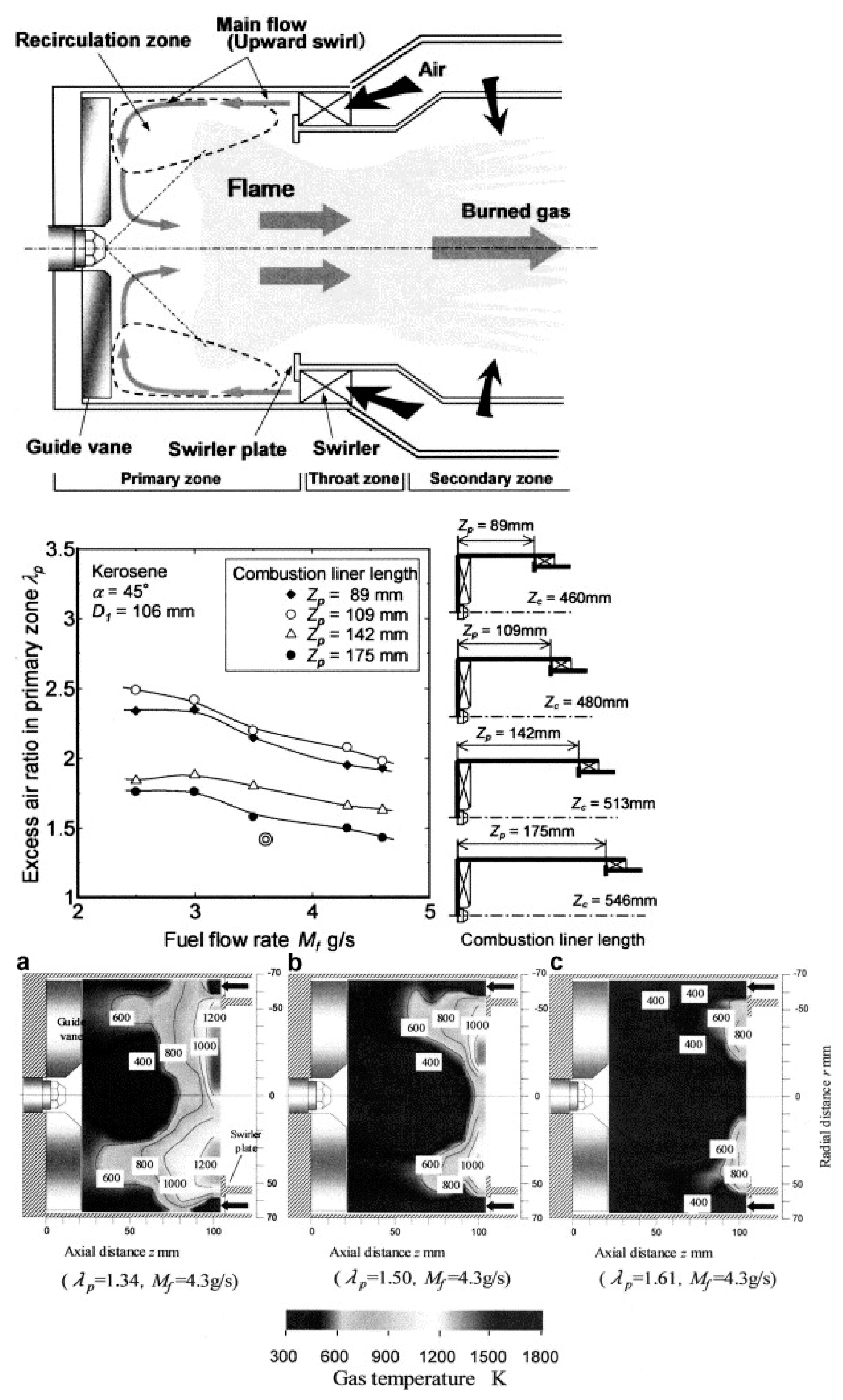
  104. Furuhata, T.; Amano, S.; Yotoriyama, K.; Arai, M. Development of can-type low NOx combustor for micro gas turbine (fundamental characteristics in a primary combustion zone with upward swirl). Fuel 2007, 86, 2463–2474. [Google Scholar] [CrossRef]
  105. Longwell, J.P.; Frost, E.E.; Weiss, M.A. Flame Stability in Bluff Body Recirculation Zones. Ind. Eng. Chem. 1953, 45, 1629–1633. [Google Scholar] [CrossRef]
  106. Kundu, K.M.; Banerjee, D.; Bhaduri, D. On Flame Stabilization by Bluff-Bodies. J. Eng. Power 1980, 102, 209–214. [Google Scholar] [CrossRef]
  107. Wright, F. Bluff-body flame stabilization: Blockage effects. Combust. Flame 1959, 3, 319–337. [Google Scholar] [CrossRef]
  108. Kundu, K.M.; Banerjee, D.; Bhaduri, D. Theoretical Analysis on Flame Stabilization by a Bluff-Body. Combust. Sci. Technol. 1977, 17, 153–162. [Google Scholar] [CrossRef]
  109. Tang, A.; Cai, T.; Deng, J.; Xu, Y.; Pan, J. Experimental investigation on combustion characteristics of premixed propane/air in a micro-planar heat recirculation combustor. Energy Convers. Manag. 2017, 152, 65–71. [Google Scholar] [CrossRef]
  110. Kim, W.H.; Park, T.S. Effects of Blade Angle on Combustion Characteristics in a Micro Combustor with a Swirler of Micro Fan Type. JMST Adv. 2019, 1, 65–71. [Google Scholar] [CrossRef]
  111. Kedia, K.S.; Ghoniem, A.F. The blow-off mechanism of a bluff-body stabilized laminar premixed flame. Combust. Flame 2015, 162, 1304–1315. [Google Scholar] [CrossRef]
  112. Chen, X.; Li, J.; Zhao, D.; Rashid, M.T.; Zhou, X.; Wang, N. Effects of porous media on partially premixed combustion and heat transfer in meso-scale burners fuelled with ethanol. Energy 2021, 224, 120191. [Google Scholar] [CrossRef]
  113. Deshpande, A.A.; Kumar, S. On the formation of spinning flames and combustion completeness for premixed fuel–air mixtures in stepped tube microcombustors. Appl. Therm. Eng. 2013, 51, 91–101. [Google Scholar] [CrossRef]
  114. Khandelwal, B.; Deshpande, A.A.; Kumar, S. Experimental studies on flame stabilization in a three step rearward facing configuration based micro channel combustor. Appl. Therm. Eng. 2013, 58, 363–368. [Google Scholar] [CrossRef]
  115. Wan, J.; Zhao, H. Laminar non-premixed flame patterns in compact micro disc-combustor with annular step and radial preheated channel. Combust. Flame 2021, 227, 465–480. [Google Scholar] [CrossRef]
  116. Xiao, H.; Howard, M.; Valera-Medina, A.; Dooley, S.; Bowen, P.J. Study on Reduced Chemical Mechanisms of Ammonia/Methane Combustion under Gas Turbine Conditions. Energy Fuels 2016, 30, 8701–8710. [Google Scholar] [CrossRef]
  117. Yang, W.; Chou, S.; Shu, C.; Li, Z.; Xue, H. Combustion in micro-cylindrical combustors with and without a backward facing step. Appl. Therm. Eng. 2002, 22, 1777–1787. [Google Scholar] [CrossRef]
  118. Zhong, B.-J.; Wang, J.-H. Experimental study on premixed CH4/air mixture combustion in micro Swiss-roll combustors. Combust. Flame 2010, 157, 2222–2229. [Google Scholar] [CrossRef]
  119. Cai, S.; Su, Z.; Xie, P.; Zeng, Q.; Wan, J. Combustion and thermal characteristics of a miniature double-layer disc-combustor with porous media and Swiss-roll preheated channel. Chem. Eng. Sci. 2023, 267, 118356. [Google Scholar] [CrossRef]
  120. Kundu, K.P.; Penko, P.J.; Yang, S.L. Simplified Jet-A/Air Combustion Mechanisms for Calculation of NOx Emissions. In Proceedings of the 34th AIAA/ASME/SAE/ASEE Joint Propulsion Conference and Exhibit, Cleveland, OH, USA, 13–15 July 1998; American Institute of Aeronautics and Astronautics Inc., AIAA: Reston, VA, USA, 1998. [Google Scholar] [CrossRef]
  121. Shantanu, M.; Reddy, V.M.; Karmakar, S. Experimental and numerical studies on heat recirculated high intensity meso-scale combustor for mini gas turbine applications. Energy Convers. Manag. 2018, 176, 324–333. [Google Scholar] [CrossRef]
  122. Wierzbicki, T.A.; Lee, I.C.; Gupta, A.K. Performance of synthetic jet fuels in a meso-scale heat recirculating combustor. Appl. Energy 2014, 118, 41–47. [Google Scholar] [CrossRef]
  123. Wu, M.-H.; Yetter, R.; Yang, V. Combustion in Meso-Scale Vortex Combustors: Experimental Characterization. In Proceedings of the 42nd AIAA Aerospace Sciences Meeting and Exhibit, Reno, NV, USA, 5–8 January 2004; American Institute of Aeronautics and Astronautics: Reston, VA, USA, 2004. [Google Scholar] [CrossRef]
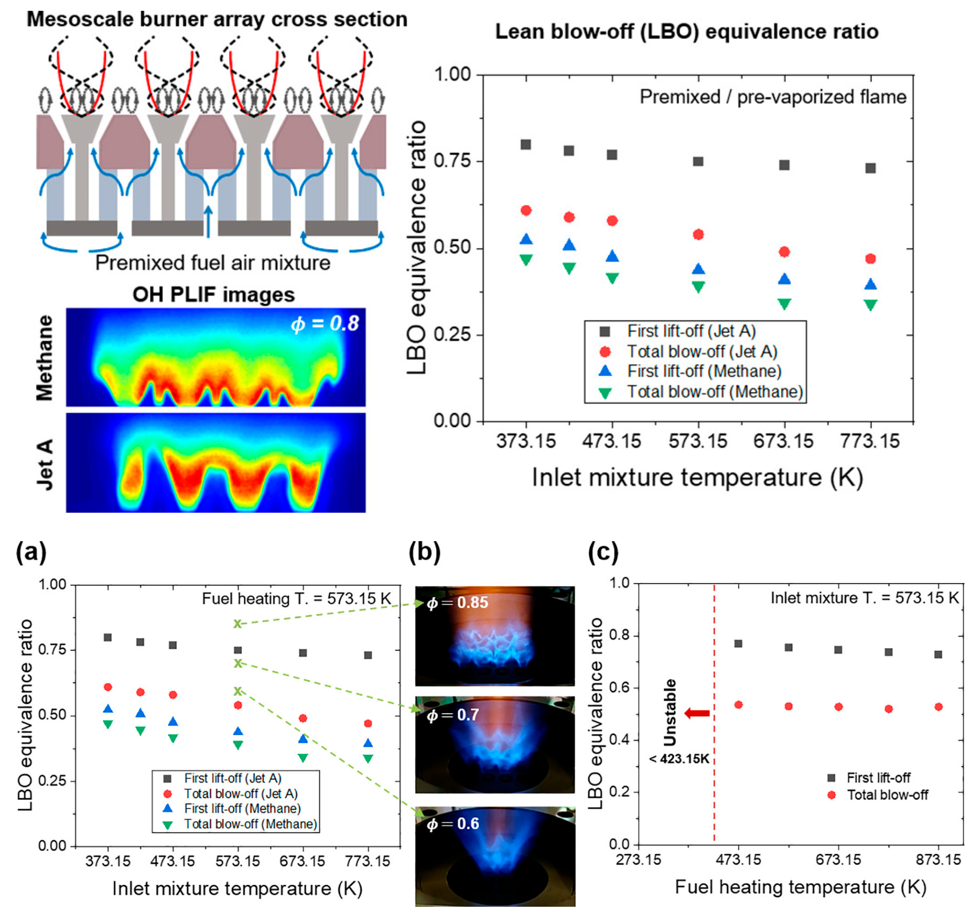
  124. Rajasegar, R.; Mitsingas, C.M.; Mayhew, E.K.; Liu, Q.; Lee, T.; Yoo, J. Development and Characterization of Additive-Manufactured Mesoscale Combustor Array. J. Energy Eng. 2018, 144, 04018013. [Google Scholar] [CrossRef]
  125. Rajasegar, R.; Choi, J.; McGann, B.; Oldani, A.; Lee, T.; Hammack, S.D.; Carter, C.D.; Yoo, J. Mesoscale burner array performance analysis. Combust. Flame 2018, 199, 324–337. [Google Scholar] [CrossRef]
  126. Guiberti, T.F.; Zimmer, L.; Durox, D.; Schuller, T. Experimental Analysis of V- to M-Shape Transition of Premixed CH4/H2/Air Swirling Flames. In Proceedings of the Volume 1A: Combustion, Fuels and Emissions; American Society of Mechanical Engineers: New York, NY, USA, 2013. [Google Scholar] [CrossRef]
  127. Bardos, A.; Walters, K.M.; Boutross, M.G.; Lee, S.; Edwards, C.F.; Bowman, C.T. Effects of Pressure on Performance of Mesoscale Burner Arrays for Gas-Turbine Applications. J. Propuls. Power 2007, 23, 884–886. [Google Scholar] [CrossRef]
  128. Lee, S.; Svrcek, M.; Edwards, C.F.; Bowman, C.T. Mesoscale Burner Arrays for Gas-Turbine Reheat Applications. J. Propuls. Power 2006, 22, 417–424. [Google Scholar] [CrossRef]
  129. Ning, D.; Liu, Y.; Xiang, Y.; Fan, A. Experimental investigation on non-premixed methane/air combustion in Y-shaped meso-scale combustors with/without fibrous porous media. Energy Convers. Manag. 2017, 138, 22–29. [Google Scholar] [CrossRef]
  130. Kang, X.; Veeraragavan, A. Experimental demonstration of a novel approach to increase power conversion potential of a hydrocarbon fuelled, portable, thermophotovoltaic system. Energy Convers. Manag. 2017, 133, 127–137. [Google Scholar] [CrossRef]
  131. Sirignano, W.A.; Pham, T.K.; Dunn-Rankin, D. Miniature-scale liquid-fuel-film combustor. Proc. Combust. Inst. 2002, 29, 925–931. [Google Scholar] [CrossRef]
  132. Wu, M.-H.; Yetter, R.; Yang, V. Development and Characterization of Ceramic Micro Chemical Propulsion and Combustion Systems. In Proceedings of the 46th AIAA Aerospace Sciences Meeting and Exhibit, Reno, NV, USA, 7–10 January 2008; American Institute of Aeronautics and Astronautics: Reston, VA, USA, 2008. [Google Scholar] [CrossRef]
  133. Li, Q.; Li, J.; Shi, J. Fully-resolved 3D premixed H2/air flames in a micro-combustor partially filled with porous media: Effects of detailed pore structures. Proc. Combust. Inst. 2022; in press. [Google Scholar] [CrossRef]
  134. Peng, Q.; Yang, W.; Jiaqiang, E.; Xu, H.; Li, Z.; Yu, W.; Tu, Y.; Wu, Y. Experimental investigation on premixed hydrogen/air combustion in varied size combustors inserted with porous medium for thermophotovoltaic system applications. Energy Convers. Manag. 2019, 200, 112086. [Google Scholar] [CrossRef]
  135. Qian, P.; Liu, M.; Li, X.; Xie, F.; Huang, Z.; Luo, C.; Zhu, X. Effects of bluff-body on the thermal performance of micro thermophotovoltaic system based on porous media combustion. Appl. Therm. Eng. 2020, 174, 115281. [Google Scholar] [CrossRef]
  136. Yoo, C. Direct Numercial Simulations of Strained Laminar and Turbulent Non Premixed Flames: Computational and Physcial Aspects; University of Michigan: Ann Arbor, MI, USA, 2005. [Google Scholar]
  137. Tanaka, S.; Shimura, M.; Fukushima, N.; Tanahashi, M.; Miyauchi, T. DNS of turbulent swirling premixed flame in a micro gas turbine combustor. Proc. Combust. Inst. 2011, 33, 3293–3300. [Google Scholar] [CrossRef]
  138. Tyliszczak, A.; Boguslawski, A.; Nowak, D. Numerical simulations of combustion process in a gas turbine with a single and multi-point fuel injection system. Appl. Energy 2016, 174, 153–165. [Google Scholar] [CrossRef]
  139. Benard, P.; Moureau, V.; Lartigue, G.; D’Angelo, Y. Large-Eddy Simulation of a hydrogen enriched methane/air meso-scale combustor. Int. J. Hydrogen Energy 2017, 42, 2397–2410. [Google Scholar] [CrossRef]
  140. Wang, X.; Deng, Y.; Liu, Y. Numerical studies on the combustion of ultra-low calorific gas in a divergent porous burner with heat recovery. Int. J. Hydrogen Energy 2022, 47, 27703–27715. [Google Scholar] [CrossRef]
  141. Wei, J.; Peng, Q.; Shi, Z.; Xie, B.; Kang, Z.; Ye, J.; Fu, G. Investigation on the H2 fueled combustion with CH4 and C3H8 blending in a micro tube with/without fins. Fuel 2022, 328, 125314. [Google Scholar] [CrossRef]
  142. Wu, S.; Laurent, T.D.C.; Abubakar, S.; Li, Y. Thermal performance characteristics of a micro-combustor with swirl rib fueled with premixed hydrogen/air. Int. J. Hydrogen Energy 2021, 46, 36503–36514. [Google Scholar] [CrossRef]
  143. He, Z.; Yan, Y.; Zhao, T.; Zhang, Z.; Mikulčić, H. Parametric study of inserting internal spiral fins on the micro combustor performance for thermophotovoltaic systems. Renew. Sustain. Energy Rev. 2022, 165, 112595. [Google Scholar] [CrossRef]
  144. Kim, W.H.; Park, T.S. Effects of noncircular air holes on reacting flow characteristics in a micro can combustor with a seven-hole baffle. Appl. Therm. Eng. 2016, 100, 378–391. [Google Scholar] [CrossRef]
  145. Choi, H.S.; Suzuki, K. Large eddy simulation of turbulent flow and heat transfer in a channel with one wavy wall. Int. J. Heat Fluid Flow 2005, 26, 681–694. [Google Scholar] [CrossRef]
  146. Woodfield, P.L.; Nakabe, K.; Suzuki, K. Numerical study for enhancement of laminar flow mixing using multiple confined jets in a micro-can combustor. Int. J. Heat Mass Transf. 2003, 46, 2655–2663. [Google Scholar] [CrossRef]
  147. Yahagi, Y.; Sekiguti, M.; Suzuki, K. Flow structure and flame stability in a micro can combustor with a baffle plate. Appl. Therm. Eng. 2007, 27, 788–794. [Google Scholar] [CrossRef]
  148. Kim, W.H.; Park, T.S. Reacting flow characteristics based on the axis-switching phenomenon in a baffled micro combustor with rotated noncircular holes for micro-thermophotovoltaic system. Int. J. Heat Mass Transf. 2022, 195, 123169. [Google Scholar] [CrossRef]
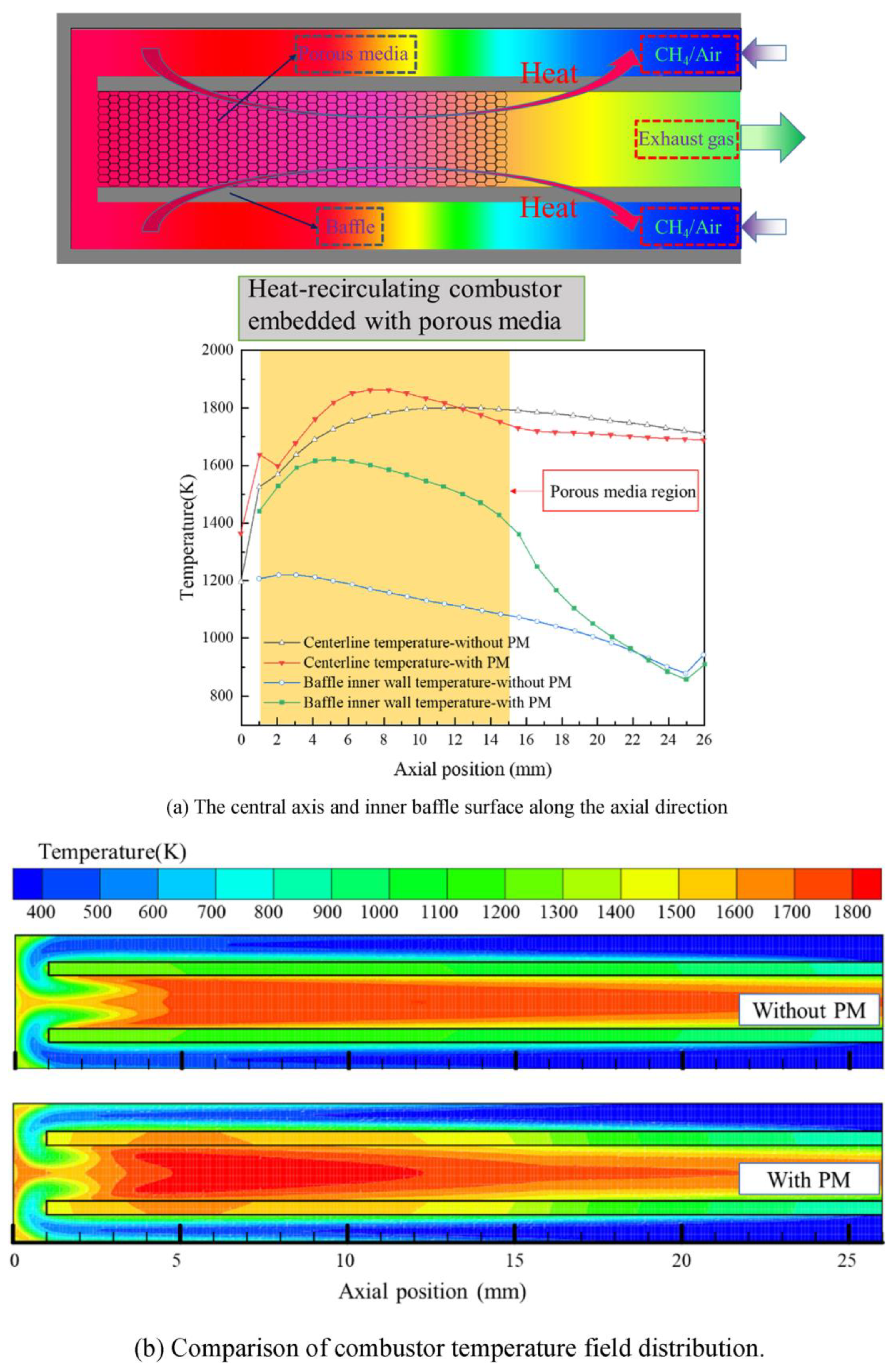
  149. Yan, Y.; Zhang, C.; Wu, G.; Feng, S.; Yang, Z. Numerical study on methane/air combustion characteristics in a heat-recirculating micro combustor embedded with porous media. Int. J. Hydrogen Energy 2022, 47, 20999–21012. [Google Scholar] [CrossRef]
  150. Boyarko, G.A.; Sung, C.-J.; Schneider, S.J. Catalyzed combustion of hydrogen–oxygen in platinum tubes for micro-propulsion applications. Proc. Combust. Inst. 2005, 30, 2481–2488. [Google Scholar] [CrossRef]
Figure 1. The number of publications containing “Micro-meso Combustors” research studies published during 2000 and 2022 (Source: Scopus database; Date of search: September 2022 Micro-Meso Scale Combustion).
Energies 16 03968 g001
Figure 2. Gas Turbine Engine combustors with wide range of operating conditions, Reused with permission from [34]. Copyright © 2013 Elsevier Ltd.
Energies 16 03968 g002
Figure 3. Observation of vortex structure in unstable combustion with different configurations: (a) High frequency “screech” instability; (b) Low frequency instabilities in a backward facing step geometry; (c) Low frequency instabilities of a dump combustor; (d) Large scale vortices in a premixed shear layer; (e) Vortex driven instability in a multiple jet dump combustor; (f) Vortex driven oscillation in a single jet dump combustor; (g) Organized vortex motion in a premixed ducted flame modulated by plane acoustic wave; (h) Control of a dump combustor using organized vortices; (i) Vortex motion during the injection phase of a pulse combustor. Reused with permission from [63]. Copyright © 2000 Elsevier Ltd.
Energies 16 03968 g003
Figure 4. Experimental studies on Amirkabir’s micro combustor tested liquid fuels. Reused with permission from [85,86,100]. Copyright © 2020 Elsevier Ltd.
Energies 16 03968 g004
Figure 5. Droplets SMD profile and contour (in μ) in the intermediate zone in reactive and non-reactive conditions, displaying the placement of droplets in the recirculation zones. Reused with permission from [85]. Copyright © 2020 Elsevier Ltd.
Energies 16 03968 g005
Figure 6. Concept of upward swirl combustor with lean combustion limits and temperature distributions in the primary combustion zone: (a) Excess air ratio (lp = 1.34), Fuel flow rate (Mf = 4.3 g/s); (b) Excess air ratio (lp = 1.50), Fuel flow rate (Mf = 4.3 g/s); (c) Excess air ratio (lp = 1.61), Fuel flow rate (Mf = 4.3 g/s). Reused with permission from [104]. Copyright © 2007 Elsevier Ltd.
Energies 16 03968 g006
Figure 7. Temperature distribution inside the combustor with different spray cone angles and at different operating conditions: (I) Φ = 0.38; (II) Φ = 0.31; (III) Φ = 0.27 and (IV) Φ = 0.25. (For interpretation of the colors in the figure(s), the reader is referred to the web version of this article). Reused with permission from [86]. Copyright © 2021 Elsevier Ltd.
Energies 16 03968 g007
Figure 8. Flame photos for different inlet velocities at the same equivalence ratio of 0.5: (a) Vin = 15 m/s; (b) Vin = 23 m/s; (c) Vin = 40 m/s. The inlet of the combustor is on the left side. Experimental data of exhaust gas temperature versus inlet velocity for different equivalence ratios. Reused with permission from [18]. Copyright © 2012 Elsevier Ltd.
Energies 16 03968 g008
Figure 9. Photos of stable combustion in three Swiss-roll combustors. The composition of the flue gas at exit of combustors: (a) Model I Combustor (reactant and exhaust are separated by a 1.9 mm gap); (b) Model II Combustor (reactant and exhaust are separated by a 1.9 mm gap); (c) Model III Combustor (does not have the internal gap or external thermal insulation). (Reused with permission from [118]. Copyright © 2010 Elsevier Ltd.
Energies 16 03968 g009
Figure 10. Mesoscale burner array cross section with Methane and Jet flames images at ∅ = 0.8: (a) Effect of inlet mixture temperature on the lean blow-off equivalence ratio; (b) Visible images of the Jet A flame array; (c) Effect of Jet A heating temperature on the lean blow-off equivalence ratio. “Reprinted (adapted) with permission from [26]. Copyright © 2021 American Chemical Society.”
Energies 16 03968 g010
Figure 11. Snapshot of POD analysis to study mesoscale flame dynamics using two different fuels: (a) POD mode energy contents and (b) mode structures of methane and Jet A flame array. “Reprinted (adapted) with permission from [26]. Copyright © 2021 American Chemical Society”.
Energies 16 03968 g011
Figure 12. Stable operation range and corresponding temperature of porous media at different air temperatures. Reused with permission from [112]. Copyright © 2021 Elsevier Ltd.
Energies 16 03968 g012
Figure 13. Photographs of free flame structure at Ta = 158 °C and 209 °C: (a) Direct photographs; (b) CH∗ chemiluminescence images with Abel transformation. (C1): Qf = 230 μL/min, Ta = 158 °C; (C2): Qf = 230 μL/min, Ta = 209 °C; (C3): Qf = 270 μL/min, Ta = 209 °C. Reused with permission from [112]. Copyright © 2021 Elsevier Ltd.
Energies 16 03968 g013
Figure 14. A two-staged mesoscale combustor consisting of a sub-millimeter scale catalytic reactor to produce radicals and recirculating flow for a mesoscale, dual-shelled main combustor. Reused with permission from [7,30,132]. Copyright © 2011 Elsevier Ltd.
Energies 16 03968 g014
Figure 15. Experimental results, with porous media in the center (Lpm = 9 mm). Direct photo from left to right Φ = 0.6, 0.8 and 1.0; at Uo = 2 m/s and 3 m/s for upper and lower row respectively. Measured Wall Temperature. Reused with permission from [93]. Copyright © 2010 Elsevier Ltd.
Energies 16 03968 g015
Figure 16. Instantaneous snapshots at local extinction, at t = 10.23 ms for U = 20.5 m/s: Isocontours of: (a) heat release rate (the color level is maximum at 1010 J/m3 s); (b) YOH; (c) temperature (K); (d) axial velocity (m/s); (e) magnitude of vorticity (1/s) and (f) magnitude of ∂u/∂x (1/s). A sequence of instantaneous snapshots of the isocontours of YH2O/YH2Omax = 0.5 for U = 20.5 m/s, at an increment of 10 μs starting from t = 10.27 ms. Reused with permission from [16]. Copyright © 2015 Elsevier Ltd.
Energies 16 03968 g016
Figure 17. Streamlines obtained from time-averaged velocity (left) and instantaneous distributions of heat release rate (right) on the center plane (y = 0) for: (a) S = 0.6 and (b) 1.2 in reactive flow without inflow perturbations. The region denoted by (A) represents the central recirculation zone (CRZ) (B). Small-scale vortices appear frequently in this region as mentioned. Reused with permission from [137]. Copyright © 2011 Elsevier Ltd.
Energies 16 03968 g017
Figure 18. Relation between flame and flow structures in high frequency: (a) time series of pressure fluctuation at the inlet for the low swirl number case with perturbations. conditions are extracted: (a) in downturn; (b) at a saddle point; (c) close to a local minimum and (d) in upturn; (b) volume rendering of instantaneous heat release rate and instantaneous streamlines. In the pressure conditions (a) and (d) where absolute values of the derivative are large. In contrast, the size gets small in conditions (b) and (c) where the absolute values of the derivative are small. Reused with permission from [137]. Copyright © 2011 Elsevier Ltd.
Energies 16 03968 g018
Figure 19. Contours of chamber combustion characteristics and distribution of the main species resulted from the combustion: (a) Temperature (K); (b) C10H20 mass fraction; (c) Mixture fraction; (d) CO mass fraction; (e) OH mass fraction; (f) CO2 mass fraction. Reused with permission from [85]. Copyright © 2020 Elsevier Ltd.
Energies 16 03968 g019
Figure 20. Scatter diagram illustrates the relationship between the combustion characteristics and temperature (in Kelvin) in the intermediate zone. Reused with permission from [85]. Copyright © 2020 Elsevier Ltd.
Energies 16 03968 g020
Figure 21. Velocity and temperature profiles with nine different bluff body shapes at 10 m/s, 20 m/s, and 30 m/s: (i) circular; (ii) elliptic; (iii) semicircular; (iv) semielliptic; (v) arrowhead; (vi) crescent, (vii) diamond; (viii) wall blade and (ix) wedge. Reused with permission from [13]. Copyright © 2022 Wiley.
Energies 16 03968 g021aEnergies 16 03968 g021b
Figure 22. Schematic diagram of the micro disc-combustor with an annular step and a radial preheat channel: (a) Three-dimensional view; (b) cross sectional view. Temperature contours overlaid with 10% maximum YHCO isolines (white solid lines) (left) and YHCO contours overlaid with streamlines (right) for various ϕ values at Re = 80. Re-used with permission from [115]. Copyright © 2012 Elsevier Ltd.
Energies 16 03968 g022
Figure 23. Microscale Swiss-roll combustor with Bluff body: (a) three-dimensional geometrical model; (b) horizontal cross-section; (c) vertical cross section. Temperature fields in the middle of the Swiss-roll combustors with and without a bluff body at different inlet velocities and ϕ = 0.5. Reused with permission from [19]. Copyright © 2017 Elsevier Ltd.
Energies 16 03968 g023
Figure 24. Schematics of the combustor with helical fins. The ignition process of the helical fin-anchored flame at V in = 34   m / s . The wall and flow regions are mapped with temperature and HO2 respectively in the z-slices and the inlet channel. (left) Temperature and (right) OH contours on the central plane of Y = 0 and various Z slices (the positions are indicated by yellow dash-dot lines) with overlaid flame surfaces (transparent surfaces) of (a) Step and (b) Helix combustors at increasing inlet. Reused with permission from [72]. Copyright © 2022 Elsevier Ltd.
Energies 16 03968 g024
Figure 25. Axial distributions of temperature along the centerline and iso-surfaces of Z = Zst for three baffles: (a) Temperature distributions along the centerline, and (b) temperature contours at several streamwise positions (Solid lines are Z = 0.039). Reused with permission from [144]. Copyright © 2016 Elsevier Ltd.
Energies 16 03968 g025
Figure 26. Comparison of predicted results and experimental data: (a) streamwise velocity and its fluctuation, mixture fraction, and temperature along the centerline of jet flow and (b) temperature and streamlines of a micro combustor. Reused with permission from [144]. Copyright © 2016 Elsevier Ltd.
Energies 16 03968 g026
Figure 27. Heat Recirculating combustor embedded with porous media. Effect of porous media on temperature distribution of micro combustor. The central axis and inner baffle surface along the axial directions: (a) The central axis and inner baffle surface along the axial direction; (b) Comparison of combustor temperature field distribution. Re-used with permission from [149]. Copyright © 2022 Elsevier Ltd.
Energies 16 03968 g027
Table 1. UAV classification according to the United States Department of Defense [43,44,45,46].
UAV
Category
Maximum Gross Takeoff Weight (MGTW) [lbs]SizeAirspeed
[Knots]
Normal Operating Altitude [ft]
Group 10–20Small<100<1200
Above Ground Level
Group 221–55Medium<250<3500
Group 3<1320Large<250<18,000
Mean Sea Level
Group 4<1320LargeAny airspeed<18,000
Mean Sea Level
Group 5<1320LargestAny Airspeed<18,000
Table 2. Few significant UAV/Drone Engines and its specifications [43,44,45,46,47,50,55,56,57,58,59,60,61,62].
UAV/Drone Engine Type Fuel *Endurance [h]Payload [kg]
MQ-1C Gray Eagle HFE-180HP heavy fuel EngineDiesel, Jet Fuel42227
MojaveRolls Royce M250JP-4 Aviation Kerosene, Jet fuel25+ 1633
MQ-9 Reaper Honeywell TPE331-10Jet A, A1, JP-1,4,5,8271361
Predator C AvengerPratt & Whitney PW545B turbofanJet Fuel202948
Predator XPHeavily Modified Rotax 914 Turbo4-Stroke engine
Gasoline
35147
Global Hawk, Triton,
The Embraer 145
Rolls-Royce AE 3007 TurbofanJP-8, Jet Fuel30910
RQ-7 Shadow 200AR741-1101
Single rotor Wankel-type spark ignition engine
Aviation Gasoline625.4
Northrop Grumman X-47CPratt & Whitney Canada JT15D-5C
High Bypass turbo fan
Jet fuel64500
MQ-8 Fire Scout Rolls-Royce 250-C20 W Jet Fuel121338
Harfang Rotax 914 F Gasoline, Octane AKI, Octane RON26250
Nishant ALVIS AR-801 Gasoline4.545
RQ-21 BlackjackEFI Piston EngineGasoline1618
RQ-4 Global Hawk Rolls-Royce AE3007H turbofan engineJet Fuel36860
CQ-10 Snowgoose Rotax 914 piston engineGasoline19227
Scan Eagle two-blade propeller,
Piston engine
Heavy fuel (JP-5 or JP 8) or C-10 gasoline engine20–285
RQ- 5A Hunter Moto-Guzzi Gasoline30125
Elbit Hermes 450UEL R802/R902 (W) Wankel engineRegular grade Mogas or AVGAS (100LL)20180
Watchkeeper Rotary Wankel water-cooled engine Aviation Gasoline16+150
Kronshtadt Orion Rotax 914 engineGasoline24250
CH-4 Chang Hong Lark HFE unit Wuhu-based Anhui Haery Aviation Power Heavy Fuel30115
Rustom HNPO-Saturn 36MT engines, Turbo prop Aviation Gasoline, Jet fuel24350
Wing Loong-3Turbo Prop Engine Jet Fuel402300
Sperwer A, BBombardier-Rotax 582/562UL RON 90 Octane, AV Gas 100 LL12–2450–100
Bayraktar TB2Rotax 912 enginesGasoline, Octane AKI, Octane RON   24 + 150
* Fuels for Military Applications and Domestic Applications are different.
Table 3. Different micro combustion and power systems and its development.
AuthorsType of Combustor/Power SourceIndustrial ApplicationsNumerical/Experimental StudiesKey Findings
Kentfiled [66] 1998Valveless Pulse JetsUAV, MAV Propulsion applicationsSNECMA/Lockwood aero valved designThrust augmentation flow rectifier, amplification of the thrust.
Fleming et al. [23] 2002Small-scale thermoelectric generationMicro air vehicles,
DARPA MAV,
TEG Module testing
Integration studies for DARPA
High-temperature TEG Module, Improved thermos electrical efficiency
Leach et al. [67] 2005Millimeter scale combustorUAV, MAVs, MissilesMethane air mixture of two parallel plates, Heat Recirculation with detailed chemistryComparison of the heat recirculation and flames with Hydrogen combustors
Lloyd et al. [20]
Chen et al. [68]
Li et al. [21] 2005, 2008
Kim [31]
Fan et al. [19] 2017
Wu et al. [69]
Swiss-roll Micro Scale CombustorStirling Engine, Micro heat, and Power generation, Cooling applicationsNumerical Model developments, Experimental studies, Swiss-roll Catalytic combustor, 3D CFD modellingNumerical prediction of extension limits, Heat Recirculation studies, combustion efficiency, flame stabilization, blow-off limits, system performance
Rideau [70] 2008TR60, TR 40 New bypass TurbojetMissiles, UAVsSingle spool Bypass Turbojet engineDetails about TR60, TR 40 Engine Demonstrator program
Minotti et al., Zhang et al. [71,72]
2009, 2022
Cylindrical Micro Combustor, Helical FinsPropulsion, Satellite Power systems, UAVs3D RANS Eddy dissipation Model, two-step reduced kinetic mechanisms, scaling LawsMicro Combustor Performance, Numerical Performance of EDC, Framelet model, Micro Step flame-flow Interactions
Deshpande et al. [73] 2011Backward-facing step Micro combustorMicro Power Generation, UAVsExperiment conducted with quartz micro combustors, emission measurementsEffect of geometrical configuration on flame stability limits with two-steps, three-step combustors
Wan et al. [2,13,18,19,74,75,76,77,78,79]
2012–2022
Planner Micro combustor with Bluff bodyCombustion based micro power generation and UAVs2D RANS, k-e
Experiments at 40 m/s with Digital Camera
Hydrogen/Air
Blow-off Limits at 0.2, 0.5, 0.6 Equivalence Ratio, Peak Temperature 1850 K
Hosseini et al. [80] 2014Step Micro flameless combustor with bluff bodySmall-Scale Power generation, Micro Thermophotovoltaic, Aviation3D RANS, k-e EDC model, Premixed and Non premixedCombustion efficiency enhanced due to flameless combustion, flame quenching elimination, Higher inlet velocities
Catori et al. [81]
2014
Small-Scale turbojet combustorUAVs, Drones GlidersBlast Atomizer Configuration CFD Miniature combustion chamberAtomization and Mixing characteristics, Exit temperature profiles
Zhang et al. [17]
2015
Hollow hemispherical Bluff bodyPower generation, military use aviation, Chemical Industry3D with surface catalytic reaction with Deutschman mechanism
Methane/air
Hemisphere bluff body enchanted blow-off limits by 2.5 times, tested at stoichiometric conditions
Kang et al. [24,25] 2015, 2019Mesoscale Combustor with thermally orthotropic wallMicro Propulsion systemsParallel plate mesoscale combustor, FLIR systems, Infrared cameraFlammability limits for both pyrolytic graphite and stainless-steel plate Thermal efficiency
Lee et al. [16] 2015Mesoscale channel with Bluff bodyPower generation, Gas turbine combustors2D Direct Numerical Simulations (DNS)
Hydrogen/air
Detailed visualization of the near blow-off flame characteristics
Spytek [82] 2019Turboshaft Engine T1310-SA100UAV ApplicationsMulti-inter-turbine burner enabled configurationRedeveloped configuration with inter-turbine burners, power output
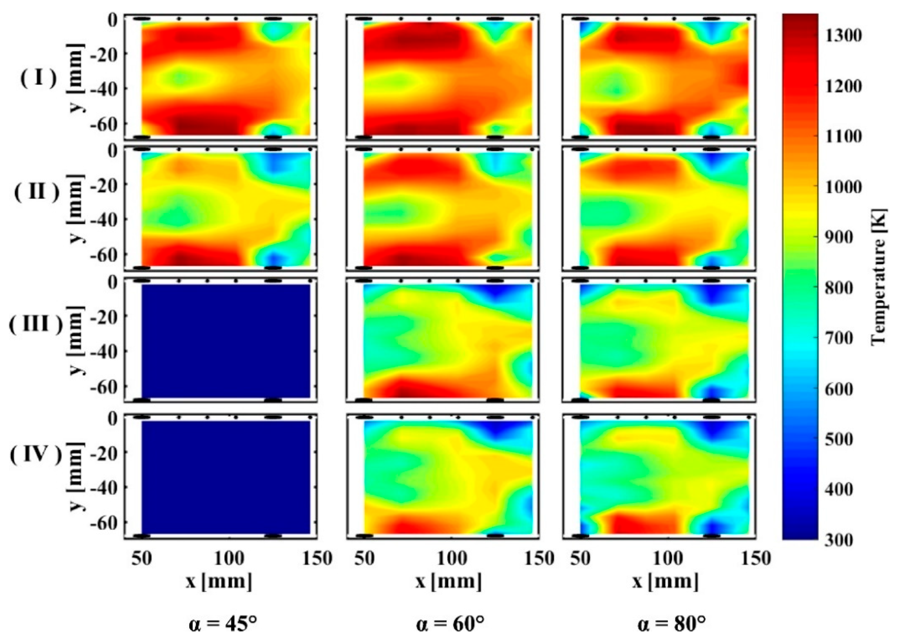
Guo et al. [83] 2020Swirl/Bluff-body BurnerPower generation, Gas turbine combustorsLES coupled with thickened flame model
Particle Image Velocimetry (PIV) Planar Laser Induced Fluorescence (OH-PLIF)
Hydrogen enriched CH4/air
Effect of Swirl, Bluff body on hydrogen flame stabilization,
Decreased Axial velocity fluctuations, attachment of the flame is weak due to lean mixture.
Zou et al. [84] 2020Narrow channel with orthotropic wallsMicrothrusters, power generation, PropulsionDNS Studies on bluff-body stabilized flames Premixed Hydrogen/airHeat loss resistance ability compared with isotropic combustors, Flame structure at higher inlet velocities
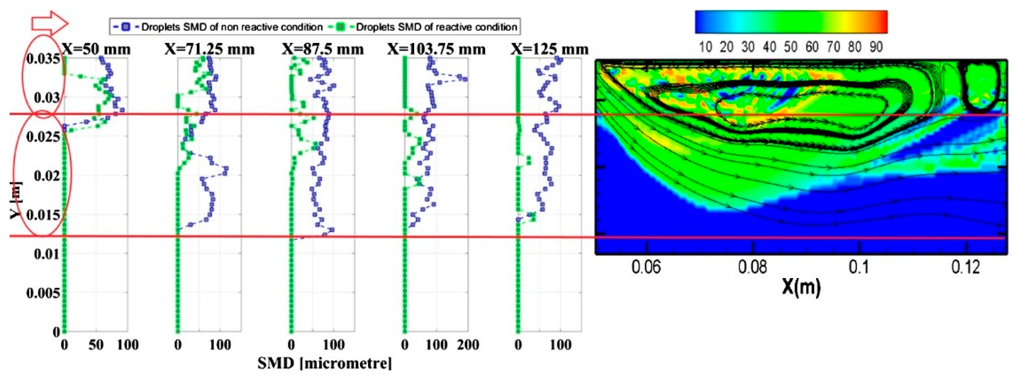
Sadatakhavi et al., Kankashvar et al. [85,86,87] 2020, 2022Can Micro CombustorJet engines, UAVs, Micro has turbinesExperimental Studies, RANS Droplet Modelling, Kerosene Liquid fuel, LES studies on oxidant jetsInner Recirculation zone and Swirl Phenomena along the liner wall, flame formation, droplet breakup, evaporation
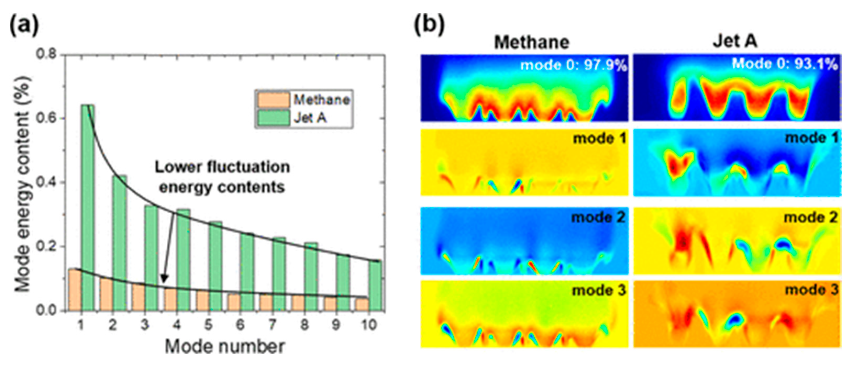
Choi et al. [26,27]
2021, 2022
Mesoscale Swirls combustorUAVs, Burners, Power GenerationExperimental with OH-PLIF Imaging Setup
Jet A-Air, Hydrogen rich Fuels
Improve small-scale flame stability, reduce length scales, overall combustion characteristics, Lean Blow-off limits
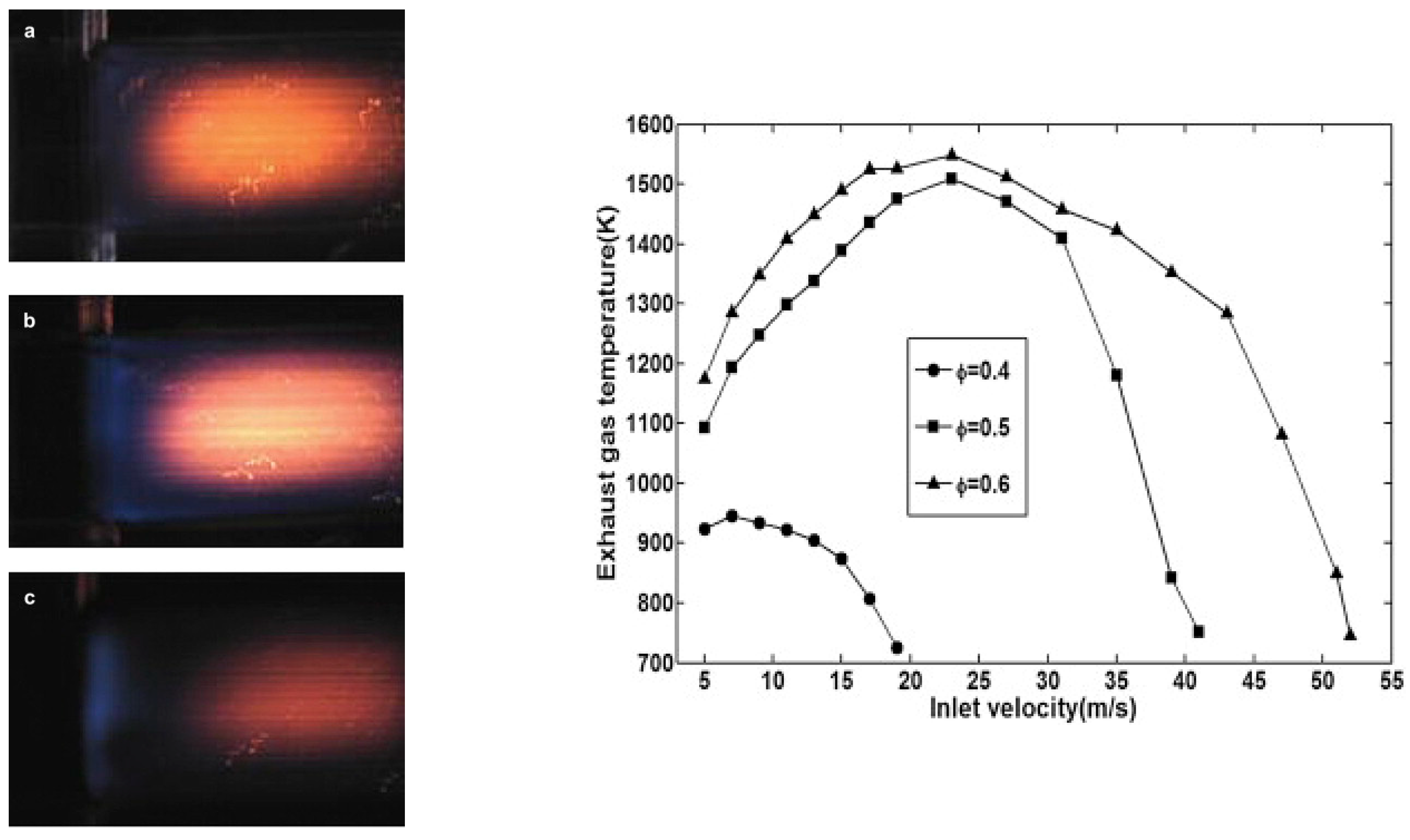
Ghali et al. [88] 2021Micromix CombustorAuxiliary Power Units, PropulsionEddy Dissipation Model with single injection
Hydrogen air
Lean mixture and influence of equivalence ratio and NOx formations
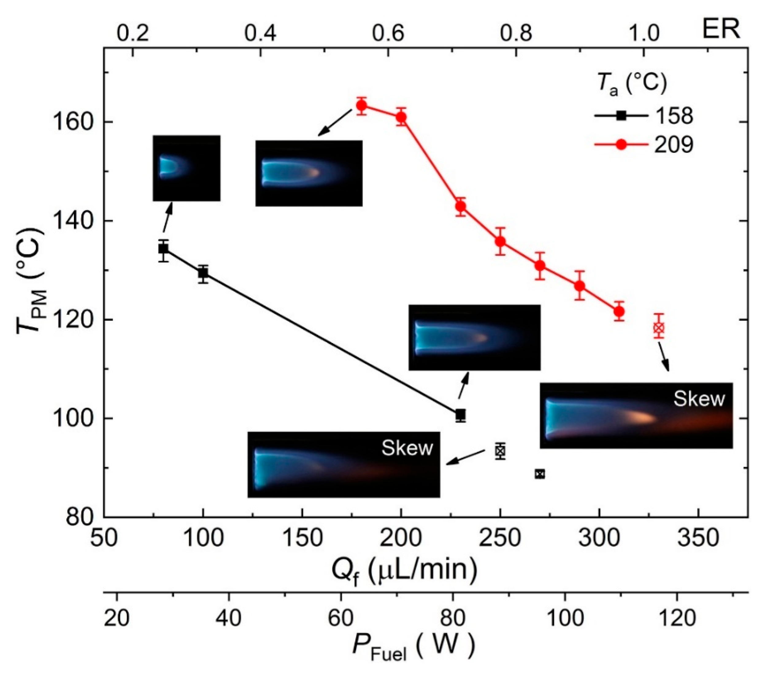
Khan et al., Zizin et al. [89,90] 2015, 2022Micro combustor with an embedded passive fuel pumpingMicro Aerial vehicles, Power GenerationNon-Premixed Ethanol combustion, flame fluctuationsAtomization at ultra-low flow rates, Heat loss from the combustors
Disclaimer/Publisher’s Note: The statements, opinions and data contained in all publications are solely those of the individual author(s) and contributor(s) and not of MDPI and/or the editor(s). MDPI and/or the editor(s) disclaim responsibility for any injury to people or property resulting from any ideas, methods, instructions or products referred to in the content.

