Article

Power Distribution System Outage Management Using Improved Resilience Metrics for Smart Grid Applications

by
Arif Fikri Malek
1,
Hazlie Mokhlis
1,*,
Nurulafiqah Nadzirah Mansor
1,
Jasrul Jamani Jamian
2,*,
Li Wang
3 and
Munir Azam Muhammad
4
1
Department of Electrical Engineering, Faculty of Engineering, Universiti Malaya, Kuala Lumpur 50603, Malaysia
2
Faculty of Electrical Engineering, Universiti Teknologi Malaysia, Johor Bahru 81310, Malaysia
3
Department of Electrical Engineering, College of Electrical Engineering & Computer Science, National Cheng Kung University, Tainan City 70101, Taiwan
4
Department of Electrical Engineering, Iqra University, Karachi 75500, Pakistan
*
Authors to whom correspondence should be addressed.
Energies 2023, 16(9), 3953; https://doi.org/10.3390/en16093953
Submission received: 12 March 2023 / Revised: 26 April 2023 / Accepted: 30 April 2023 / Published: 8 May 2023

Abstract

:
Smart grid systems play a significant role in improving the resilience of distribution systems (DSs). In this paper, two strategies are proposed for implementation of a smart grid application: (a) a network reconfiguration and (b) a network reconfiguration with mobile emergency generator (MEGs) deployment. An improved set of resilience metrics to quantify and enhance the resiliency of distribution systems (DSs) is developed for the proposed optimization. The metrics aim to determine a suitable strategy and the optimal number and capacity of MEGs to restore the disconnected loads through the development of several microgrids. These metrics are then aggregated with the proposed strategy to develop an automated solution provider. The objective is to maximize system resilience considering the priority loads. The proposed resilience metrics are tested on the IEEE 33-Bus radial DSs. The case studies conducted proved the performance of the proposed power outage management strategy and resilience metrics in maximizing system resiliency for smart grids.

1. Introduction

Catastrophic events, including cyber security attacks, natural calamities and wars, can cause detrimental effects on the operation of distribution systems (DSs), leading to massive damage and large-scale power outages [1]. Over the last few years, there have been countless incidents of power interruptions due to natural calamities. For instance, in 2012, hurricane Sandy was disastrous in the United States [2], and, in 2011, Japan experienced the Tohoku earthquake [3]. With awareness of these difficulties, it is crucial to strengthen the resilience of DSs [4]. The resilience of DSs can be defined as the indicator that shows the system’s performance when facing high-impact, low probability events [5]. The resilience of DSs has tremendously improved with the advent of smart grid systems and the incorporation of several techniques and energy resources into the systems, such as microgrids (MGs), network reconfiguration (NR), mobile emergency resources (MEGs) and resilience metrics.
MGs can operate in either connected or islanded modes and play a major role in the smart grid by providing energy reserves via distributed resources. Several recent studies in [6,7] have demonstrated that the storage capacity of MGs can be utilized to optimize energy consumption in smart grid systems. However, more recently, there has been considerable interest in using the storage abilities of MGs to enhance the resilience of the smart grid against emergency events, such as natural disasters or security breaches. In this regard, various academic, industrial and federal reports [8,9] have proposed leveraging MG storage capacity to mitigate the effects of generation loss during emergencies by meeting the smart grid’s most critical loads. The presence of network reconfiguration (NR) in MG formation has played an essential role in the smart grid through the provision of self-healing systems, and, thus, preserve several emergency operations in the United States, such as hospitals and police stations [10].
Network reconfiguration (NR) is one of the methods considered for improving DS resilience. An hourly NR that considers distributed energy resources, such as wind farms and electric vehicles, is proposed in [11] to improve the system’s resiliency during normal and emergency situations. The preventive–corrective model incorporating a two-stage optimization technique was proposed in [12] to enhance system resilience. The initial stage of the proposed approach involves pre-scheduling energy storage systems (ESSs) and conducting a network reconfiguration (NR) process to minimize the anticipated cost of load outage, based on fault forecasting data. The second stage of the proposed technique involves network restoration after the actual event by using corrective NR to minimize the actual cost of load outage. Based on cyber–physical–social system (CPSS) aspects, a novel methodology is proposed in [13] that encompasses the simultaneous scheduling of RCs, MEGs and energy resources. A mixed integer non-linear optimization model is developed with the aim of minimizing the load outage, operation time and cost. A rapid action for service restoration is proposed in [14], utilizing the remote-controlled switches (RCSs) and NR during the planning and operational stage.
In addition to the NR method, various studies have been proposed on the deployment of mobile emergency generators. Reference [15] proposed an optimization model considering the travel route, routing and deployment time of mobile resources to allow prompt service restoration, thus enhancing resilience of DSs. A post-disaster recovery technique is developed in [16] aimed at minimizing outage costs and customer interruption. The author considered NR and scheduling mobile emergency storage systems during the restoration process. To minimize the size of power failure, Ref. [17] proposed a two-stage positioning (before and after the event) of emergency mobile resources through the formation of multiple microgrids (MGs). A power outage management model of decentralized microgrids is proposed in [18] which considers multiple stages with the aim of minimizing operating costs and unserved energy. In this study, NR and the deployment of MEGs and an RC team have been considered in the optimization model. Ref. [19] proposed a bi-level restoration method that takes into account the connection between roadways and power lines. The first stage involves pre-allocating charging and maintenance stations using a combination of Bayesian networks and Monte Carlo simulations. During the second stage, the deployment of MESSs and RC teams is prioritized for providing services to the affected areas based on critical load weighting. Ref. [20] proposed a two-stage stochastic model aimed at mitigating the issue of superfluous MEG scheduling by establishing an optimal plan for MEG planning. First, the investment in MEGs is determined, followed by their dispatch based on DS damage to optimize load supply. Ref. [21] proposed a novel approach to enhance the resilience of DSs through the integration of additional distributed energy resources (DERs). Ref. [22] discussed the current status and history of resilient cyber-physical security, covering its development background, current situation and perspectives on emerging technology and energy policy. This study summarizes how optimal control strategies and emerging technologies are used to investigate both simulations and real systems.
There are numerous definitions and methods being implemented in relation to the resilience of power systems [23]. However, standardization and consistency in statistically defining resilience metrics are lacking [24]. Researchers in the field of resilience are producing their own individual concept of resilience by broadening its area and making it more effective [25]. Ref. [26] proposed a time-dependent metric considering the ratio of the load recovery over the loss in its performance. Ref. [27] proposed a quantitative metric to access distribution system performance by concentrating on the effects of critical loads under catastrophic events. Multi-stage quantitative resilience metrics are proposed in [28], focusing on the disturbance, post-disturbance and restoration stages to provide a specific transition between these stages. In order to examine equipment failures and data packet losses in depth, resilience metrics are proposed in [29]. These metrics are developed to evaluate the stability of data and equipment systems.
According to previous literature, the stationary power sources and ESSs utilized in [11,12] respectively, have limited load recovery, particularly when no restoration path is provided to reach the defective area. Although [13] was capable of minimizing the load outage, operation time and cost through the co-scheduling of RCs, MEGs and energy resources, the model framework is not capable of analyzing the full potential of NR and MEGs individually. Consequently, the involvement of NR and mobile MEGs is inevitable in every case. Compared to [13], this paper emphasizes the impact of quantification metrics in selecting the optimal approach for power outage management. The implementation of metrics in power outage management strategies will allow the utility to deploy the MEGs only when necessary. The proposed power classification technique (PCT) relating to MEGs sizing will also help the utility to limit the number of MEGs deployed by utilizing the full potential of each MEG.
In addition, although the implementation of mobile emergency resources in [15,16,17,18] can dynamically mitigate the impact of power disruption, no methodology or set of metrics has been developed to deploy the correct number of MEGs needed, e.g., the amount of MEG dispatch for every scenario is always identical regardless of its actual needs. As a result, transportation costs have grown, and the capacity of MEGs has been underutilized. Although [19] managed to improve recovery speed and minimize the load outage using a bi-level restoration method, there is no integration between MESSs and the model, where MESSs will still be deployed regardless of necessity. As compared to the proposed method, MEGs will remain at the depot whenever the NR strategy is sufficient to serve the outage region. Despite achieving a reduction in dispatched MEGs within the specified scenario, the quantity of MEGs required in [20] remains constrained by the initial allocation of MEG investment. Hence, in situations where DSs encounter high-load outages, it is plausible that certain loads may remain unattended by MEGs due to the financial constraints imposed on MEGs. Although [21] managed to fully exploit the potential of distributed energy resources (DERs), their immobility presents significant inflexibility during restoration processes, particularly in cases where the outage area is geographically distant from the location of the DERs. This may result in some areas remaining unserved, particularly during high-load outage scenarios. Despite the efficient methods proposed in [22], operations and decision-making capacities have greatly enhanced as a result of the ongoing advancement of information technology. Consequently, the system’s risk management is becoming more unstable and uncertain. As a result, there are many elements of the smart grid that need investigation, e.g., how technology advancement can be useful for utilities by offering a completely automated system, and how the integration of a system solver with the DERs, such as MEGs, can provide the utility with effective power outage management and monitoring system improvements.
Additionally, the generic metric defined in [26] is limited to quantifying the ratio of load recovery to load loss over a specified time span, resulting in an incomplete measurement of resilience efficiency at the operational level. Meanwhile, the metric in [27] only quantifies the ratio of load loss that concentrates on critical loads in a given time. Although a set of quantitative metrics has been proposed in [28] which consider the pre-disturbance, disturbance and post-disturbance phases, the metrics are incapable of providing the real time quantification for each fault occurrence during the disturbance stage. There are also no decision-making-based metrics for selecting the optimal solution for restoration service, e.g., how the metrics indicator in the pre-restoration stage can alert the utility and help it choose the optimal strategy to mitigate load degradation. Thus, the metrics are limited to quantifying these phases individually. The metrics developed in [29] are meant to evaluate the stability of data and equipment systems. In contrast, the resilience metrics proposed in this study strive to establish a real-time monitoring system that covers all operational stages. Thus, the utility will benefit from a comprehensive monitoring system through the use of these resilience indicators. Moreover, the metrics serve as automated solution providers for selecting the most suitable solution for power outage management in smart grid systems. As a result, metrics in [26,27,28,29] are unable to portray a comprehensive picture of system resilience during the operational stage.
The above technical deficiencies are addressed in this paper with major contributions as follows:
(1)
A power outage management strategy is established which encompasses two potential approaches: (1) an NR-based technique and (2) a combination of NR and MEG-based techniques. A new power classification technique (PCT) related to the sizing capacity of MEGs is introduced to fully maximize MEG capabilities and consequently minimize the number of MEGs that has to be dispatched;
(2)
Novel metrics are proposed to serve the utility with an effective monitoring system by performing a systematic quantification technique and hence improve the DSs with the power outage management strategy. Note that the metrics alone are not used to enhance the resilience of DSs but also quantification, selection of the optimal approach and provision of an automated solution provider for the utility. This is achieved when the proposed metrics with a power outage management strategy are embedded together in the system. The automated solution provider includes the following:
  • Provide the utility with a continuous update of system performance during the disturbance and restoration stages by using the proposed metrics;
  • Generate an optimal approach for the utility with metrics indicators acting as an input for the selection process.
The remainder of the paper is arranged in the following manner: The power outage management methodology is explained in Section 2 while Section 3 describes the formulation of the model framework. Section 4 discusses the empirical result, and Section 5 summarizes this paper.

2. Power Outage Management Strategy

2.1. Quantitative Metrics in Distribution System Resiliency

The improvement made to the previous resilience metrics is presented in this section. Table 1 shows three existing metrics proposed in [26]. In [26], the metrics access the ratio of recovery over the loss. Я F t r e r indicates the system’s ability to recover following the disturbance. The value of Я F t r e r is equal to 1 when the system has completely recovered from its degradation phase. Conversely, Я F t r e r is equal to 0 when there is no action taken to recover the system. In [27], the metrics quantify the average load loss, emphasizing the critical load. R indicates the resilience index of the system while Δ P ( X s ) denotes three distinct load classifications categorized as non-critical, semi-critical and critical loads. X s is the fault scenario, M is the sampling number and P o is the total weighted load prior to the disturbance. In [28], the metrics measure resilience in three phases. In phase I, metrics Φ and Λ are defined to access the degradation speed and the amount of load outage, respectively. In phase II, metric E aims to quantify the time taken before the system is restored. Meanwhile, in phase III, the ratio of load restored to the time taken to complete the process is quantified using metric Π .
A few limitations have been identified in these metrics as summarized below:
(1)
Degradation (phase I): Refs. [27,28] have produced only a general time dependent metric capable of quantifying the degradation status after the disturbance has occurred. Meanwhile, the quantification metrics proposed in this study are used to give a continuous update of system degradation every 30 min. This information will allow the utility to provide prompt action during the event, e.g., remotely reconfigure the network during the degradation phase to serve the affected region. However, the metrics proposed in this study are used to provide a continuous quantification and no network reconfiguration will be conducted during the degradation stage.
(2)
Pre-restoration (phase II): The metrics in [28] are only capable of quantifying the total preparation time needed before the restoration is initiated. In this regard, providing a set of metrics that can respond to the system’s severity and equipping the utility with an optimal solution is required. The metrics proposed in this study will not just focus on quantifying the amount of load outage but will also be capable of selecting the optimal approach and, thus, provide the utility with an effective power outage management.
(3)
Restoration (phase III): Although metrics in [26,28] are effective in evaluating the degree of resilience, they are inadequate for demonstrating the transition of the restoration processes. Thus, continuous quantification metrics are needed to provide a real time update during the restoration process, e.g., the delay in the process could be due to a longer traveling distance or time required for manual switching. This specific information can be portrayed using the proposed metrics, and, thus, will benefit the utility with future improvements.
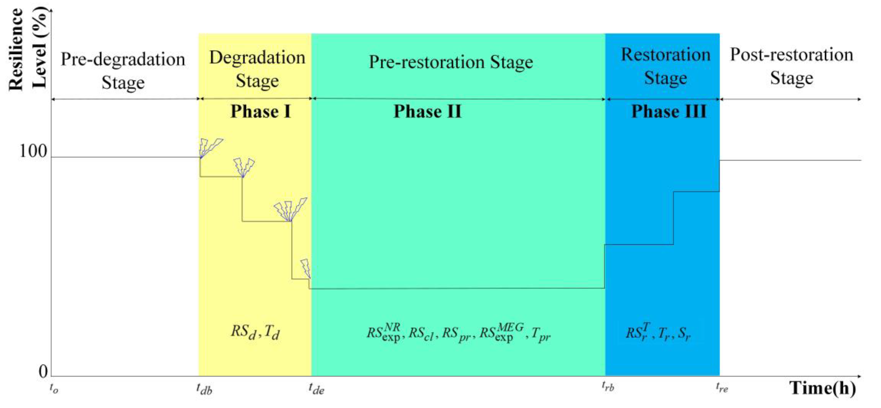
Therefore, the above limitations of existing metrics are improved by the proposed metrics in this paper which are presented in Table 2. To provide clarity to the reader, the proposed metrics are further explained with the help of the flowchart in Figure 1. In phase I, the actual system degradation is quantified using the R S d T metric at t t d b , t d e , which encompasses its severity and interruption rate. In this paper, the quantification is made for every 30 min and the maximum degradation time, T d , is assumed to be 8 h. Note that the number of scenarios and the duration of the event in this study are considered a simulation set up where Monte Carlo simulations (MCS) are used to produce the probability of occurrence based on the data from the fragility curve. Since the selected scenarios will be the scenarios that cause high impact of failure, it is assumed that there will only be multiple events that occurred in the system. The proposed metrics will continuously quantify and record the degradation status until t = t d e .
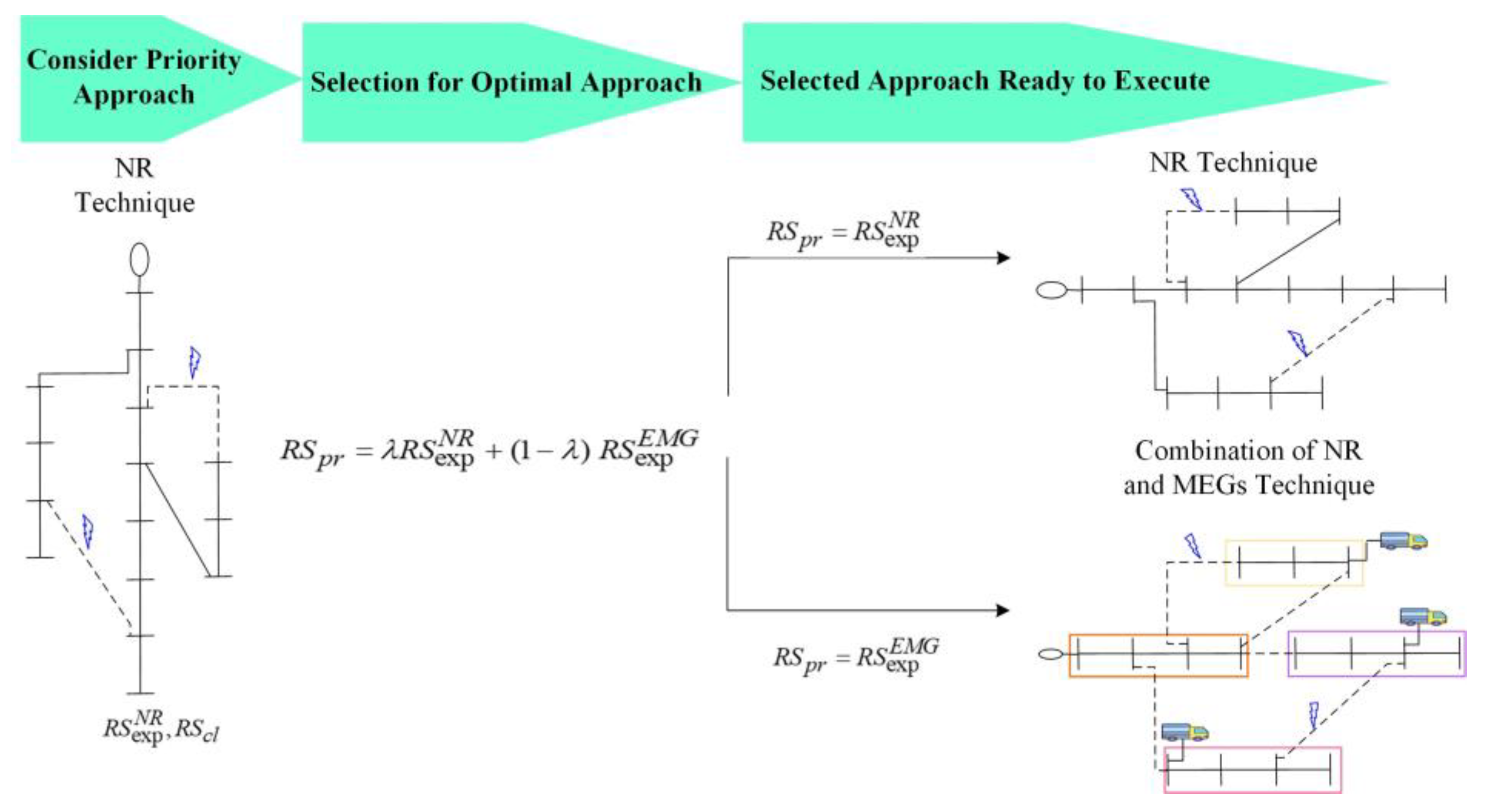
In phase II, two approaches are proposed in this model. The NR technique is considered the first strategy to serve the load. Meanwhile, the second strategy for serving the load outage considers the NR and MEG techniques. Note that the repair crews, (RC), will execute only the optimal solution. However, the priority is given to the first strategy (NR technique) to restore the system. The R S exp N R metric was developed to quantify the expected loads served from the NR technique, while metric R S C L aims to quantify the ratio of critical load outage. The R S C L metrics consists of three parameters which are critical load outage, C L o , s ; semi-critical load outage, S C L o , s ; and initial load demand, S C L T + C L T . The R S C L value can vary from 0 to 1 . The distinction between metrics R S exp N R and R S C L is essential to alert the utility in advance so that adequate resources can be provided to ensure that all critical and semi-critical loads are completely restored. Depending on the binary variable decision, λ , the R S p r metric is developed to select the optimal solution to be executed for service restoration. λ will be equal to 1 if all critical loads are served; R S C L = 0 with the NR approach, thus making R S p r = R S exp N R . Conversely, λ will be equal to 0 when all critical loads are not served by the NR approach; hence, 0 < R S C L 1 and the second approach is considered, making R S p r = R S exp M E G . The R S exp M E G metric is proposed to quantify the anticipated load served from the second approach. The T p r metric aims to quantify the total pre-restoration time. As shown in Figure 1, the evaluation of the T p r metric starts after the first RC or the MEG teams reach the selected bus, assuming the system is ready to be restored.
In Phase III, after the optimal solution is initiated, the R S r T metric will start to quantify the amount of load served during the restoration period at t t r b , t r e . As soon as the affected area begins to receive service again, the system will immediately begin quantifying the restoration status. Note that the quantification process will be affected by the traveling distance of MEGs and the switching time. The number of tie lines to connect will also affect the quantification procedure, as there are only two RC teams responsible for making the switches. After the restoration process has finished, the time taken to complete service restoration, T r , is quantified using the metric t r e t r b . Note that the time taken for manual switching of the tie lines is assumed to be 30 min [5]. The S R metric quantifies the total system resilience, ranging from 0% to 100%. S R is 100% if the system has fully restored while S R is 0% if the system has degraded to the point where it cannot mitigate the power outage.

2.2. Resilience Performance Curve

Resilience curves presented in [26,28] are used for comparison with the improved resilience curve demonstrated in Figure 2 below. This is intended to highlight the capability of the proposed resilience curve to portray a comprehensive and clear transition of the system’s performance. Resilience curve proposed in [26] consists of a few elements that exist at each stage which can be represented as original stage, S o ; disturbance stage, S d ; restoration stage, S f ; and the value of system performance corresponding to each stage, F ( t ) . Meanwhile, resilience curve proposed in [28] consists of pre-degradation operational resilience, R 0 o ; pre-degradation infrastructure resilience, R o i ; post-degradation operational resilience, R p d o ; and post-degradation infrastructure resilience, Furthermore, the improved resilience curve depicted in Figure 2 below indicates the output produced by the metrics indicator. Note that, in this study, the improvement made for three phases focus on the operational stage; the evolution from the existing trapezoid curve is discussed as follows:
(1)
Degradation (Phase I): The linear degradation curve employed in [26,28] indicates that the metrics can only access the system’s degradation after the event has finished. This approach has portrayed an incomplete picture of system resiliency during the event, e.g., how much the system has been affected at a given point in time, and for how long can the system adapt before facing the next event. Thus, a non-linear degradation curve is proposed in Figure 2 to show the volatility of system resiliency due to the unpredictable number and duration of faults;
(2)
Pre-restoration (Phase II): No strategy has been presented in the existing curve to mitigate the power outages. Thus, it is not capable of portraying a clear picture of how the system is prepared to dynamically respond to the disturbance. References [26,28] only highlights the time required to initiate the plan. Figure 3 shows the illustration made to portray the proposed decision-making process to provide the best approach for the utility;
(3)
Restoration (Phase III): The existing linear restoration curves depicted in [26,28] are incapable of displaying the actual performance of the executed plan, i.e., the manual switching process of tie lines and the movement of operators from the depot would add a delay in the restoration process.

2.3. MEGs Dispatch Strategy

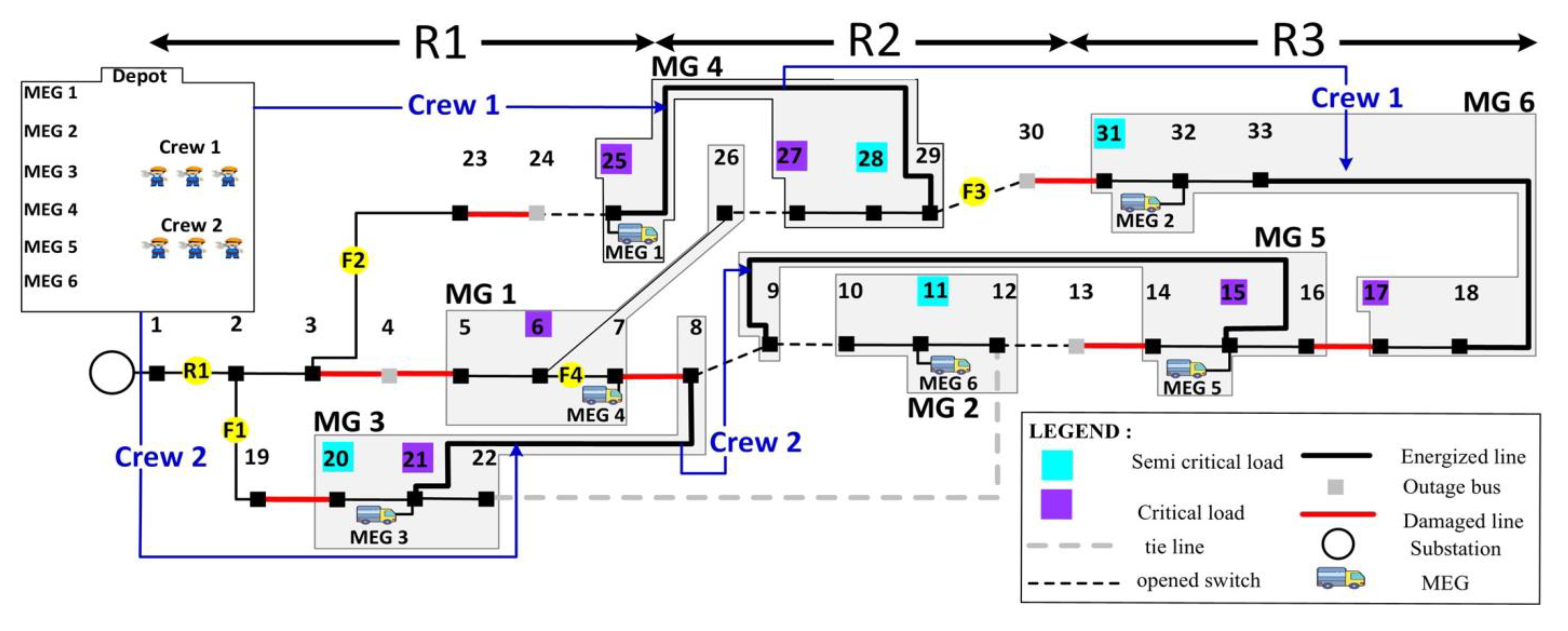
This paper proposed optimal dispatch of MEGs to several buses in the distribution network. After the ideal location for MEG placement has been determined in the pre-restoration stage, MEGs are deployed to the respective buses. MEGs then begin to develop several MGs that perform in the islanded mode to restore the disconnected loads weighted to their priorities. To fully exploit MEG capabilities and, thus, reduce the number of MEGs dispatched, the capacity of MEGs is classified into different percentages from the rated output. To provide a comprehensive estimation of MEG travel time, three regions have been introduced in the test system in to show the increment in the traveling distance of MEGs from the depot to the selected buses. These regions are denoted as R1, R2 and R3 in this paper. Microgrids powered by the MEGs are developed upon arrival to mitigate the effect of the power outage.

3. Problem Formulation

In this section, the proposed power outage management strategy is discussed. Additionally, the power flow formulation for DSs is described, along with MEG deployment.

3.1. Objective Function

Equation (1) is the objective function focusing on maximizing system resilience; S R is weighted to critical loads. L r , s indicates the amount of load restored at bus S at time t . Meanwhile, L s f defines the load factor at bus S . The objective function is maximized subject to the different groups of constraints presented in the following sections.
M a x i m i z e S R = t T s b L r , s L s f

3.2. Constraints

In the NR technique, constraints (2)–(18) are to optimize the objective function (1). Moreover, in the technique that combines NR with MEGs, the same objective function (1) is now maximized, dependent on constraints (2)–(25) which consider MEG parameters.
  • Network Reconfiguration Constraints
A fictitious substation Κ s f at the bus is used in the following mathematical formulation. The fictitious substation is a technique used in mathematical programming to conduct network reconfiguration. The presence of Κ s f is meant to keep the connection with the non-restored part while maintaining the switch status of DSs. Additionally, every load bus is connected to the fictitious substation by artificial branches, which transfer the artificial power flow required by those buses in the non-restored region. It is important to mention that the optimization technique used in the DSs during the restoration process is also employed in fictitious substation and artificial branches. The presence of a fictitious substation and artificial branches is required to ensure that the radial topology is achieved in the non-restored region while maintaining its switch status. The absence of a fictitious substation may lead to a false switch operation in the unrestored portion in order to fulfil (10).
Equations (2) and (3) indicate the real and reactive power constraints. It should be emphasized that when the NR technique is used, the parameter of real and reactive power related to MEGs in (2) and (3) is inconsiderable.
p s b r P p s , t + P s , t g + P s , t M E G = s r b r P s r , t + P s r , t l o s s + P s d 1 d s , t t T , s b
p s b r Q p s , t + Q s , t g + Q s , t M E G = s r b r Q s r , t + Q s r , t l o s s + Q s d 1 d s , t t T , s b
Constraints (4) and (5) denote the voltage magnitude at every bus. Constraint (6) mentions the apparent power magnitude of the lines.
V s , t s q r 2 R s r P s r , t + X s r Q s r , t R s r 2 + X s r 2 I s r , t s q r V r , t s q r = f s r , t t T , s r b r
f s r , t V max 2 V min 2 1 x s r , t
V r , t s q r I s r , t s q r P s r , t 2 + Q s r , t 2
The bus voltage at each bus is governed by constraint (7), ensuring that the values remain within the allowable range. Constraint (8) prohibits the line currents from exceeding the current carrying capacity.
V min 2 V s , t s q r V max 2 t T , s b
I s r , t s q r C s r 2 ¯ x s r , t t T , s r b r
Constraint (9) shows the network radiality constraint that each switching process must satisfy. The MEG parameter in (9) ensures that no selected MEG is deployed to a location served by the main grid. As a result, the upper stream will only have a single energy source. Constraint (10) represents the artificial power flow in the non-restored bus to ensure the connection and network radiality for the outage region. In this case, d s , t = 1 when the bus has not been restored; hence, artificial power flow supplied by fictitious substation Κ s f is required in the bus. Thus, the non-restored bus needs to be connected with the fictitious substation via an artificial branch. This technique ensures that the unrestored zone is connected in a radial topology and requires no switching action in that region. However, if the bus is restored then d s , t = 0 . Therefore, Equation (10) has no effect because the artificial power flow is zero since there is no branch connection between the fictitious substation and the node.
s r b r b f x s r , t = Κ b Κ s s b Y s , t M E G t T ,
p s b r b f A p s , t s r b r b f A s r , t + A s , t g = d s , t s b , t T .
Constraint (11) reinforces that only the fictitious bus will generate the artificial power flow. Constraint (12) ensures that the artificial power flow in a circuit is regulated by monitoring the circuit’s operation status. Constraints (13) and (14) restrict the fictitious bus from generating real and reactive power. Constraint (15) specifies that at least one circuit must be linked to a load bus. Constraints (16) and (17) limit the real and reactive power flow in a branch from exceeding the maximum apparent power when the branch is connected and ensures that the value is zero if otherwise. Constraint (18) indicates the fault occurrence with respect to time.
A s , t g = 0 s b , s Κ s f ,
A s r , t M x s r , t s r b r b f ,
P f b g = 0 ,
Q f b g = 0 ,
p s b r b f X p s , t + s r b r b f X s r , t 1 t T ,
P s r , t V max C s r ¯ x s r , t t T , s r b r ,
Q s r , t V max C s r ¯ x s r , t t T , s r b r ,
x s r , t x s r , t f a u l t 0 s r b r , t T .
  • MEGs Constraints
Constraints (19)–(25) are for the MEG dispatching strategy. Constraint (19) ensures that all MEGs that have been picked at the selected bus will be counted while (20) guarantees that the selected MEGs for each microgrid will not be the same.
j 1 J c P C d g 1 M E G G s , d g 1 , j 1 , c = Y s , t M E G s b ,
j 1 J c P C s b G s , d g 1 , j 1 , c 1 d g 1 M E G .
Constraint (21) determines the optimal real power fed into the selected bus. To avoid harmful effects on the mobile generators, the proposed classification of MEG power generation is set to operate at greater than 50% of rated capacity [30]. Nevertheless, multiple percentage categories are introduced that vary from (50–100%) to ensure that the model correctly matches the MEG rating capacity for each microgrid’s power demand. This approach will restrict the model to deploy the correct number of MEGs required by fully leveraging their capacities. Constraint (22) prohibits MEGs from selecting a capacity that has already been selected by another MEG.
P s , t M E G j 1 J c P C d g 1 M E G P e r c c D G j 1 c a p G s , d g 1 , j 1 , c t T , s b ,
d g 1 M E G c P C s b G s , d g 1 , j 1 , c 1 j 1 J ,
Constraint (23) specifies that the total amount of MEGs chosen must fall within the allowable range. Constraint (24) limits the amount of reactive power fed into the bus from chosen MEGs. However, the magnitude is subject to (25). Constraint (25) is the real power injected into the selected bus as determined by the power capacity of the available MEGs.
s b Y s , t M E G Y max M E G t T ,
Q s , t M E G P s , t M E G tan θ Y s , t M E G t T , s b ,
P s , t M E G j 1 Y s , t M E G j 1 J , t T , s b .

4. Results and Discussion

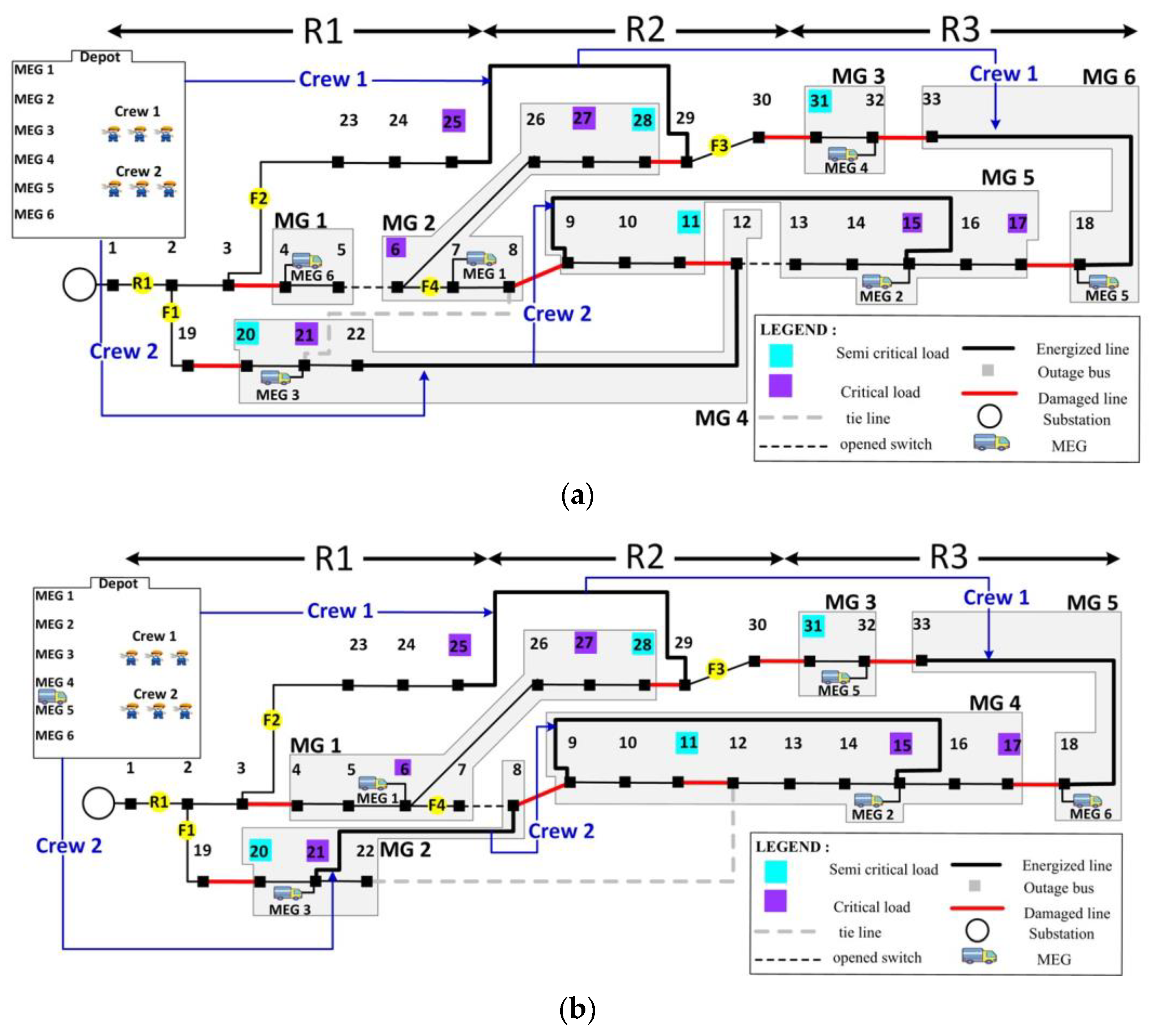
The performance and effectiveness of the proposed power outage management strategies and metrics were validated on a standard IEEE 33-bus radial DSs. The details related to IEEE 33-bus can be obtained in [31,32] respectively. Three different load classifications, i.e., critical, semi-critical, and non-critical, are assigned in this system, with respective weights of eight, five and one. The automatic line sections are presumed to be available on all lines except the tie lines to activate prompt switching actions. Two RC teams are presumed to be stationed at the depot, and all selected MEGs and RC teams will be deployed simultaneously with a preparation time of 20 min before deployment. Moreover, the traveling time of MEGs from the depot to the specific location is also considered by assuming three regions (R1, R2 and R3), as shown in Figure 4. The assumed times for reaching R1, R2 and R3 are 30 min, 45 min and 60 min, respectively. Nevertheless, these traveling times can be changed accordingly in the model. The developed model was optimized using mixed-integer quadratic constraint programming (MIQCP), and all simulations were performed in AMPL IDE software. CPLEX was used as a solver in AMPL IDE that utilizes branch and bound algorithms. The ratings of all available MEGs are presented in Table 3. A Monte Carlo simulation (MCS) was performed where the failure probability produced by the fragility curve based in [33] serves as an input to the simulation. Afterwards, a non-sequential selection approach was considered to select ten scenarios for testing. Table 4 ranked the selected scenarios according to their failure probabilities from the lowest to the highest. Note that the arrangement of damaged lines for each scenario represents the transition and the different faults that occurred at a certain period. To closely match the load demands at each microgrid when it needs to be formed, this paper assumed three classifications of MEG power generation: 50%, 70% and 100% of their rated capacity. Nevertheless, the proposed model is adaptable to any other required percentage of capacity. Two case studies are presented in this paper to validate the major contributions of this study.

4.1. Case I: 33-Bus System

4.1.1. I(a): Power Outage Management and PCT on MEGs

In this section, a comparison is made between the performance of MEGs with PCT and MEGs without PCT. The results presented are meant to highlight the first major contribution in this study. It is presumed that scenario 9 will take place during the disturbance stage. Following the disturbance, the second approach is considered the optimal approach. Figure 4 shows the number of MEGs deployed before and after the implementation of PCT. In Figure 4a, six MEGs have been considered to serve the load outage due to the absence of PCT. In Figure 4b, only five MEGs are required to restore the entire system. The presence of PCT has allowed the model to search through the MEG capacity before the microgrid is developed. As a result, the MEGs managed to serve more buses and, thus, restricted the number of MEGs deployed.
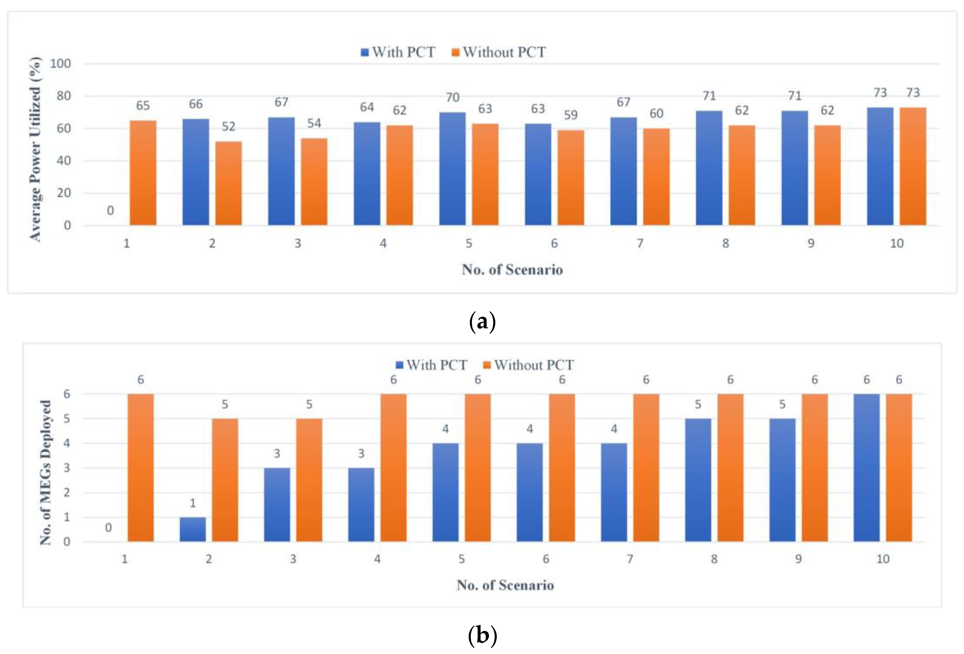
Table 5 shows the comparison of the average power utilized by the MEGs. It is evident that, with the presence of PCT, the average power utilized is higher when compared to without the PCT. The allocation of five MEGs has boosted the average active power consumption up to 73%. Meanwhile, when six MEGs are deployed, the average active power utilized is 63%. Therefore, maximizing the full potential of each MEG will result in a smaller number of MEGs being deployed. To thoroughly examine the impact of PCT in each scenario, the average power utilized, and the number of MEGs deployed are presented in Figure 5. As can be seen, the presence of PCT has caused the number of MEGs deployed in most scenarios to be smaller, resulting in larger power utilization. Note that, in scenario 1, the average power utilized is zero since there are no MEGs deployed during the restoration process. Based on the power outage management strategy, the NR approach is found to be sufficient to restore the entire system in scenario 1; thus, no MEGs need to be deployed. In scenario 10, the average power utilized is equal since all MEGs are required to serve the outage region in both cases. Thus, it can be concluded that the capabilities of each MEG can be more utilized when their power generation is specifically classified.

4.1.2. I(b): Resilience Metrics and Quantitative Approach

The results presented in this section correspond to the second major contribution of this study. A comparison is made with [26] to demonstrate the capability of the proposed metrics for producing detailed information related to system performance, thus leading to a comprehensive monitoring system. It is assumed that scenario 10 will unfold during the event. Table 6 demonstrates the progression of metrics indicators in quantifying the DSs, while Table 7 summarizes the performance of previous metrics. Meanwhile, Figure 6 shows the line status following every event that occurred in scenario 10. Figure 6 is presented to help understand the quantification process discussed in phase I.
In phase I, the proposed metrics will quantify the load status at every bus and the process is repeated every 30 min until the event stops. The R S d 1 metric shows the result of the first quantification made during the first 30 min. At t = 30 , there has been no disaster in the DSs, thus making R S d 1 = 0 kW. Note that this value will then be updated throughout the subsequent quantification process. The first event occurred at t = 60 on L 16 17 , causing both L 16 17 and L 17 18 to be de-energized. The disturbance has resulted in degradation level R S d 2 = 150 kW. Then, the second event is spotted at t = 90 on L 13 14 causing a total of 5 lines ( L 13 14 to L 17 18 ) to be de-energized. As a result, the degradation level has increase from R S d 2 = 150 kW to R S d 2 = 390 kW. As shown in Figure 6, the amount of de energized lines increases in proportion to the increase in the degradation value. Later, the degradation level remained constant between t = 120 and t = 150 , making both R S d 4 and R S d 5 equal to 390 kW. At t = 180 , the third event landed on lines L 7 8 , L 19 20 and L 30 31 , leading to current degradation level R S d 6 = 1565 kW. After that, at t = 210 , the DSs faced the fourth event causing the degradation level to increase from R S d 6 = 1565 kW to R S d 7 = 2385 . This value has remained constant until t = 240 due to the absence of an event, resulting in R S d 8 = 2385 . The DSs facing the last event (fifth event) a t = 270 make the total degradation level R S d T = R S d 9 = 3345 kW. As a result, nine quantification processes were performed during the deterioration period, with a total degradation time of T d = 4.5 hours recorded. No metric has been proposed in [26] to quantify the system degradation. Meanwhile, the average load loss measured by metric R in [27] is 1.90. Additionally, the degradation rate Φ and total degradation Λ in [28] are −743 kW/hour and 3345 kW, respectively. As can be seen, the existing metrics in [27,28] are only capable of quantifying the performance of DSs after the event has stopped.
There are no indicators that have been developed in [26,27] for phase II; however, the total pre-restoration period measured by metric E in [28] is 0.83 h. Meanwhile, a set of decision-making metrics proposed in this paper are used to select the optimal approach to execute. The NR approach is first considered to restore the system. As shown in Table 6, R S exp N R is obtained by thoroughly quantifying the individual expected load served from L exp N R , 1 to L exp N R , 33 and adding all the values. From the NR simulation, the expected amount of load served obtained by metric R S exp N R is equal to 370 kW. The simulation result indicates that the NR approach is not an ideal solution since R S C L = 1 . Thus, λ = 0 and R S p r = R S exp M E G . Afterward, the system starts to simulate the second approach. In this approach, R S exp M E G is calculated by thoroughly quantifying each expected load served from L exp , 1 M E G to L exp , 33 M E G and adding the values. The total expected served load obtained by metric R S exp M E G is equal to 2915 kW. The result shows that the second approach is the optimal solution due to its capability to serve all critical loads. After the simulation has been completed, the utility will then deploy all the selected MEGs to each selective node; total time needed during pre-restoration stage T p r is equal to 0.83 h.
In phase III, after the arrival of MEG4 at bus 7, MG1 is formed and restored immediately since no manual switching is needed. This action has restored certain regions of the DSs, thus making R S = r 1 750 kW. The dispatch of the RC teams and MEGs in scenario 10 is presented in Figure 7. After 65 min at t = 335 , MEG6 arrived at Bus 11, and MG2 is developed, resulting in a cumulative load restored R S = r 2 915 kW. Later, both RC1 and RC2 arrived at L 25 29 and L 8 21 , respectively. An additional 30 min is needed to change the line status, and MG3 and MG4 are formed after 80 min. The developed microgrid has improved the restoration level from R S = r 2 915 kW to R S = r 3 2045 kW. Meanwhile, MG5 is restored by MEG5 after 125 min, resulting in R S = r 4 2345 kW. More time is needed during this process due to the long traveling distance by RC1 and the additional time required for manually switching on L 9 15 . Last, MG6 is created by MEG2 after 140 min, making R S = r T R S = r 5 2915 kW. As illustrated in Figure 7, six MEGs have been deployed and four bus outages due to an insufficient number of MEGs. Upon completing the restoration process, the DSs has achieved system resilience, S R = 78.46 % , and the total restoration time is T r = 1.5 hour. The number of EMGs dispatched in [26,27,28] is zero, and 28 buses are out, including ten critical loads. Furthermore, the ratio of load recovery to load loss measured by metric Я F t r e r in [26] is 0 since there is no increment in the resilience level when the NR approach is implemented. Moreover, [27] did not develop a metric in phase III, whereas [28] has quantified the restoration rate using a metric Π of 0 kW/hour. Thus, as presented in Figure 8, although the resilience of DSs has not been fully restored, the proposed metrics managed to demonstrate their ability to provide a comprehensive quantification process in both the degradation and restoration phases. It is evident that, although the previous metrics have been implemented in the same model, no EMGs were successfully deployed by the metrics indicator. This situation happened due to the lack of integrated development of the decision-making metrics in [26]. Additionally, integrating metrics into the system has enabled an autonomous selection process and constant monitoring of system performance. Furthermore, to scrutinize the impact in each scenario, the performance of the resilience indicator is presented in Figure 9 and Table 8. Table 8 shows both the ability of the PCT and the decision-making metrics proposed in this study. In scenario 1, the disturbance that occurred for T d = 1.5 hour has caused R S d T = R S d 2 = 615 kW. Following the disturbance, the NR approach is first considered for system restoration. The R S exp N R value in Table 8 is obtained by thoroughly quantifying the individual expected load served from L exp N R , 1 to L exp N R , 33 and adding all the values. From the NR simulation, the expected amount of load served obtained by metric R S exp N R is equal to 3715 kW. The simulation results reveal that the NR method is the optimal solution since R S C L = 0 ; thus, λ = 1 and R S p r = R S exp N R . Before the system starts to recover, RC teams are deployed to the selective tie line to conduct the switching process manually. In addition, all MEGs have stayed at the depot since no MEGs are required throughout the restoration process. The system is fully restored during the restoration phase, where R S r T = 3715 kW, and the total restoration time is T r = 1 . Therefore, scenario 1 proved that implementing the proposed technique can significantly reduce the number of MEGs deployed while achieving S r = 100 % .
Finally, Table 8 demonstrates the performance of MEGs from scenario 2 to scenario 10. It can be seen from Figure 5b and Table 8 that the number of MEGs deployed increases as the number of load outages increases. The execution of the optimal approach has reduced the R S C L value to zero. In addition, with the automatic switching process in place, the system performed a relatively rapid service restoration. Therefore, it is proven that the proposed method is capable of improving the resilience of DSs. It is important to mention that the proposed method is also capable of being implemented in other test systems since the solver implemented in this study can be integrated with the commercial solver.

5. Future Work

Power distribution outage management incorporating NR and a combination of NR and MEG deployment for enhancing the resilience of DSs was proposed in this study. The following are a few studies that are worth investigating in the future:
(1)
The combination of distributed generators (DGs) with MEGs has not been considered in this study. The presence of DGs will have significant effects on improving resilience. Consequently, future studies that are worth investigation include determining the optimal sizing and placement of DGs when MEGs are being considered while allowing for the multi-level recovery process;
(2)
Renewable energy resources and mobile energy storage systems (MESS) are not included in this study. The advantages of renewable resources and MESS can be maximized, and the implementation could possibly reduce operational risk during catastrophic events.

6. Conclusions

In this paper, the potential of MGs, DGs, NR and resilience metrics has been exploited in an attempt to enhance the resilience of smart grid systems. A power outage management strategy based on optimal network reconfiguration and MEG deployment has been modeled, along with resilience quantification metrics. The proposed optimization framework is validated on standard IEEE 33-bus radial DSs. By integrating the proposed resilience metrics into the model, the optimal strategy was achieved whilst exploiting the beneficial effect of NR and MEGs. In contrast, the existing metrics proposed by previous researchers are only capable of quantifying the system’s performance. This has driven the system to only select the NR approach in each scenario. The limitations of previous metrics have shown that no MEGs could be deployed. From the presented scenarios, the power classification technique of MEGs managed to fully reduce the number of MEGs deployed. The results indicate a good improvement of resiliency from 70% to 100% of load restoration. Although the system did not achieve 100% system resiliency in certain scenarios, the results confirmed that the proposed metrics and the power outage management strategy could help the utility effectively and optimally mitigate the power outage, and, thus, improve the resilience of smart grid systems.

Author Contributions

Conceptualization, A.F.M., H.M. and L.W.; methodology, A.F.M. and H.M.; software, A.F.M., H.M. and M.A.M.; validation, H.M., N.N.M. and J.J.J.; formal analysis, A.F.M. and H.M.; resources, A.F.M., H.M. and M.A.M.; writing—original draft preparation, A.F.M.; writing—review and editing, A.F.M., H.M., N.N.M. and J.J.J.; supervision, H.M., N.N.M. and J.J.J.; funding acquisition, H.M. and J.J.J. All authors have read and agreed to the published version of the manuscript.

Funding

This research was supported by Malaysian Ministry of Education under Fundamental Research Grant Scheme (FRGS/1/2021/TK0/UTM/02/20) and Universiti Malaya under the Impact-Oriented Interdisciplinary Research Grant (IIRG001A-2020IISS).

Data Availability Statement

Not applicable.

Conflicts of Interest

The authors declare no conflict of interest.

Abbreviations

DSsdistribution systems
MEGsmobile emergency generators
MESSsmobile energy storage systems
MGsmicrogrids
NRnetwork reconfiguration
RCSsremote-controlled switches
RCrepair crews
DGsdistributed generators
HILPhigh-impact, low-probability
PCTpower classification technique
MCSmonte carlo simulation
MIQCPmixed integer quadratic constraint programming
IEEEinstitute of electrical and electronics engineers
AMPLa mathematical programming language

References

  1. Hussain, A.; Bui, V.-H.; Kim, H.-M. Resilience-Oriented Optimal Operation of Networked Hybrid Microgrids. IEEE Trans. Smart Grid 2017, 10, 204–215. [Google Scholar] [CrossRef]
  2. Wang, Y.; Chen, C.; Wang, J.; Baldick, R. Research on Resilience of Power Systems Under Natural Disasters—A Review. IEEE Trans. Power Syst. 2015, 31, 1604–1613. [Google Scholar] [CrossRef]
  3. Yang, Y.; Tang, W.; Liu, Y.; Xin, Y.; Wu, Q. Quantitative Resilience Assessment for Power Transmission Systems Under Typhoon Weather. IEEE Access 2018, 6, 40747–40756. [Google Scholar] [CrossRef]
  4. Yuan, W.; Wang, J.; Qiu, F.; Chen, C.; Kang, C.; Zeng, B. Robust Optimization-Based Resilient Distribution Network Planning Against Natural Disasters. IEEE Trans. Smart Grid 2016, 7, 2817–2826. [Google Scholar] [CrossRef]
  5. Xu, Y.; Liu, C.-C.; Schneider, K.P.; Tuffner, F.K.; Ton, D.T. Microgrids for Service Restoration to Critical Load in a Resilient Distribution System. IEEE Trans. Smart Grid 2016, 9, 426–437. [Google Scholar] [CrossRef]
  6. Atzeni, I.; Ordonez, L.G.; Scutari, G.; Palomar, D.P.; Fonollosa, J.R. Demand-Side Management via Distributed Energy Generation and Storage Optimization. IEEE Trans. Smart Grid 2012, 4, 866–876. [Google Scholar] [CrossRef]
  7. Atzeni, I.; Ordonez, L.G.; Scutari, G.; Palomar, D.P.; Fonollosa, J.R. Noncooperative and Cooperative Optimization of Distributed Energy Generation and Storage in the Demand-Side of the Smart Grid. IEEE Trans. Signal Process. 2013, 61, 2454–2472. [Google Scholar] [CrossRef]
  8. Arghandeh, R.; Brown, M.; Del Rosso, A.; Ghatikar, G.; Stewart, E.; Vojdani, A.; von Meier, A. The Local Team: Leveraging Distributed Resources to Improve Resilience. IEEE Power Energy Mag. 2014, 12, 76–83. [Google Scholar] [CrossRef]
  9. McGranaghan, M.; Olearczyk, M.; Gellings, C. Enhancing distribution resiliency: Opportunities for applying innovative technologies. Electr. Today 2013, 28, 46–48. [Google Scholar]
  10. U.S. Department of Energy. The Potential Benefits of Distributed Generation and Rate-Related Issues that May Impede their Expansion: A Study Pursuant to Section 1817 of the Energy Policy Act of 2005; USDOE: Washington, DC, USA, 2007. [Google Scholar]
  11. Kianmehr, E.; Nikkhah, S.; Vahidinasab, V.; Giaouris, D.; Taylor, P.C. A Resilience-Based Architecture for Joint Distributed Energy Resources Allocation and Hourly Network Reconfiguration. IEEE Trans. Ind. Inform. 2019, 15, 5444–5455. [Google Scholar] [CrossRef]
  12. Jalilpoor, K.; Ameli, M.T.; Azad, S.; Sayadi, Z. Resilient energy management incorporating energy storage system and network reconfiguration: A framework of cyber-physical system. IET Gener. Transm. Distrib. 2022, 17, 1734–1749. [Google Scholar] [CrossRef]
  13. Chen, L.; Li, Y.; Chen, Y.; Liu, N.; Li, C.; Zhang, H. Emergency resources scheduling in distribution system: From cyber-physical-social system perspective. Electr. Power Syst. Res. 2022, 210, 108114. [Google Scholar] [CrossRef]
  14. Liu, J.; Qin, C.; Yu, Y. Enhancing Distribution System Resilience With Proactive Islanding and RCS-Based Fast Fault Isolation and Service Restoration. IEEE Trans. Smart Grid 2019, 11, 2381–2395. [Google Scholar] [CrossRef]
  15. Lei, S.; Chen, C.; Zhou, H.; Hou, Y. Routing and Scheduling of Mobile Power Sources for Distribution System Resilience Enhancement. IEEE Trans. Smart Grid 2018, 10, 5650–5662. [Google Scholar] [CrossRef]
  16. Yao, S.; Wang, P.; Zhao, T. Transportable energy storage for more resilient distribution systems with multiple microgrids. IEEE Transac. Smart Grid 2018, 10, 3331–3341. [Google Scholar] [CrossRef]
  17. Lei, S.; Wang, J.; Chen, C.; Hou, Y. Mobile Emergency Generator Pre-Positioning and Real-Time Allocation for Resilient Response to Natural Disasters. IEEE Trans. Smart Grid 2016, 9, 2030–2041. [Google Scholar] [CrossRef]
  18. Mansouri, S.A.; Nematbakhsh, E.; Ahmarinejad, A.; Jordehi, A.R.; Javadi, M.S.; Marzband, M. A hierarchical scheduling framework for resilience enhancement of decentralized renewable-based microgrids considering proactive actions and mobile units. Renew. Sustain. Energy Rev. 2022, 168, 112854. [Google Scholar] [CrossRef]
  19. Li, Z.; Tang, W.; Lian, X.; Chen, X.; Zhang, W.; Qian, T. A resilience-oriented two-stage recovery method for power distribution system considering transportation network. Int. J. Electr. Power Energy Syst. 2022, 135, 107497. [Google Scholar] [CrossRef]
  20. Yuan, M.; Chen, Y.; Li, B.; Shi, S. Optimal planning of mobile emergency generators of resilient distribution system. Energy Rep. 2021, 8, 1404–1413. [Google Scholar] [CrossRef]
  21. Menazzi, M.; Qin, C.; Srivastava, A.K. Enabling Resiliency Through Outage Management and Data-Driven Real Time Aggregated DERs. In Proceedings of the 2022 IEEE Industry Applications Society Annual Meeting (IAS), Detroit, MI, USA, 9–13 October 2022; pp. 1–20. [Google Scholar]
  22. Zhang, D.; Li, C.; Goh, H.H.; Ahmad, T.; Zhu, H.; Liu, H.; Wu, T. A comprehensive overview of modeling approaches and optimal control strategies for cyber-physical resilience in power systems. Renew. Energy 2022, 189, 1383–1406. [Google Scholar] [CrossRef]
  23. Whitson, J.C.; Ramirez-Marquez, J.E. Resiliency as a component importance measure in network reliability. Reliab. Eng. Syst. Saf. 2009, 94, 1685–1693. [Google Scholar] [CrossRef]
  24. Van Breda, A.D. Resilience Theory: A Literature Review; South African Military Health Service: Pretoria, South Africa, 2001. [Google Scholar]
  25. Hollnagel, E.D.; Woods, D.; Leveson, N. Resilience Engineering: Concepts and Precepts; Ashgate Publishing, Ltd.: Surrey, UK, 2006. [Google Scholar]
  26. Henry, D.; Ramirez-Marquez, J.E. Generic metrics and quantitative approaches for system resilience as a function of time. Reliab. Eng. Syst. Saf. 2012, 99, 114–122. [Google Scholar] [CrossRef]
  27. Luo, D.; Xia, Y.; Zeng, Y.; Li, C.; Zhou, B.; Yu, H.; Wu, Q. Evaluation Method of Distribution Network Resilience Focusing on Critical Loads. IEEE Access 2018, 6, 61633–61639. [Google Scholar] [CrossRef]
  28. Panteli, M.; Mancarella, P.; Trakas, D.N.; Kyriakides, E.; Hatziargyriou, N.D. Metrics and Quantification of Operational and Infrastructure Resilience in Power Systems. IEEE Trans. Power Syst. 2017, 32, 4732–4742. [Google Scholar] [CrossRef]
  29. Jha, A.V.; Appasani, B.; Ustun, T.S. Resiliency assessment methodology for synchrophasor communication networks in a smart grid cyber–physical system. Energy Rep. 2022, 8, 1108–1115. [Google Scholar] [CrossRef]
  30. Jabeck, B. The Impact of Generator Set Underloading; Caterpillar: Peoria, IL, USA, 2014. [Google Scholar]
  31. Baran, M.E.; Wu, F.F. Network Reconfiguration in Distribution Systems for Loss Reduction and Load Balancing. IEEE Power Eng. Rev. 1989, 9, 101–102. [Google Scholar] [CrossRef]
  32. Zhang, D.; Fu, Z.; Zhang, L. An improved TS algorithm for loss-minimum reconfiguration in large-scale distribution systems. Electr. Power Syst. Res. 2007, 77, 685–694. [Google Scholar] [CrossRef]
  33. Khomami, M.S.; Jalilpoor, K.; Kenari, M.T.; Sepasian, M.S. Bi-level network reconfiguration model to improve the resilience of distribution systems against extreme weather events. IET Gener. Transm. Distrib. 2019, 13, 3302–3310. [Google Scholar] [CrossRef]
Figure 1. Systems approach in power outage management.
Energies 16 03953 g001
Figure 2. Improved resilience curve.
Energies 16 03953 g002
Figure 3. The transition of the decision-making process made by metrics indicators.
Energies 16 03953 g003
Figure 4. MEG deployment in scenario 9. (a) Before implementation of power classification technique, (b) after implementation of power classification technique.
Energies 16 03953 g004
Figure 5. Impact of PCT on the deployment of MEGs related with each scenario. (a) Average power utilized, (b) no. of MEGs deployed.
Energies 16 03953 g005
Figure 6. Line status following every event associated with scenario 10.
Energies 16 03953 g006
Figure 7. Deployment of RC teams and MEGs during restoration stage in scenario 10.
Energies 16 03953 g007
Figure 8. The transition of system performance in the operational stage related to scenario 10.
Energies 16 03953 g008
Figure 9. Resilience performance curve related to each scenario.
Energies 16 03953 g009
Table 1. Quantitative resilience metrics.
ReferencePhase CoveredMetric SymbolMetric IndicatorsUnit
[26] III Я F t r e r F t r e r F t d e r F t o F t d e r ( kW / kW )
[27] I R 1 o t 1 M s = 1 M Δ p X s P o d t Δ P ( X s ) = 6 . Δ p 1 ( X s ) + 3 . Δ p 2 ( X s ) + 1 . Δ p 3 ( X s ) ( kW / kW )
[28] I Φ R p d o R 0 o / t e e t o e MW / hours
Λ R 0 o R p d o MW
II E t o r t e e hours
III Π R 0 o R p d o / T o r t o r MW / hours
Table 2. Improved resilience metrics.
PhaseSymbolMetric IndicatorsUnit
I R S d T t = 1 t d e s = 1 b L d g , s , t d b + t kW
T d t d e t d b hours
II R S exp N R s = 1 b L exp N R , s kW
R S C L s = 1 b ( S C L o , s + C L o , s ) / S C L T + C L T ( kW / kW )
R S p r λ R S exp N R + ( 1 λ ) R S exp M E G kW
R S exp M E G s = 1 b L exp , s M E G kW
T p r t r b t d e h
III R S r T t = 1 t r e s = 1 b L r , s , t r b + t kW
T r t r e t r b h
S R R S r T / L o 100 % %
Table 3. Active and reactive power of available megs.
MEG1MEG2MEG3MEG4MEG5MEG6
P max M E G (kW)1000750600500400230
Q max M E G (kVar)620465372310248143
Table 4. Sample of 10 scenarios and their probability of failure.
ScenarioDamaged LinesProbability
#1(12–13), (32–33), (10–11)0.281
#2(13–14, 11–12), (31–32), (20–21)0.344
#3(15–16), (9–10, 19–20), (23–24)0.42
#9(11–12, 17–18, 32–33), (8–9, 28–29, 30–31), (19–20, 3–4)0.813
#10(16–17), (13–14), (7–8, 19–20, 30–31), (4–5), (3–4, 23–24)0.875
Table 5. Average active power utilized related to megs dispatched.
MEGs P max M E G (kW) Q max M E G (kVar) P max d (kW) Q max d (kVar)Average Active Power Utilized (%)
Without PCTMEG1100062064029063
MEG2750465525235
MEG3600372330155
MEG4500310360170
MEG540024815080
MEG6230143180110
With PCTMEG1100062062030073
MEG2750465585270
MEG3600372470220
MEG5400248360170
MEG6230143150110
Table 6. Progression of metrics indicators in scenario 10.
PhaseSymbolMetric IndicatorsIndicator Output#MEGs
Dispatched
I R S d T Time (minutes) t = 1 t d e s = 1 b L d g , s , t d b + t -
30 R S d 0 + [ L d g , 1 , 1 + L d g , 2 , 1 + + L d g , 33 , 1 ] R S d 1 = 0
. . . . . . . . .
270 R S d 8 + [ L d g , 1 , 9 + L d g , 2 , 9 + + L d g , 33 , 9 ] R S d 9 = 3345
T d t d e t d b 4.5
II R S exp N R L exp N R , 1 + L exp N R , 2 + + L exp N R , 33 3706
R S C L [ ( S C L o , 1 + C L o , 1 ) + + ( S C L o , 33 + C L o , 33 ) ] / S C L T + C L T 1
R S p r 0 ( R S exp N R ) + ( 1 0 ) R S exp M E G R S exp M E G
R S exp M E G L exp , 1 M E G + L exp , 2 M E G + + L exp , 33 M E G 2915
T p r t r b t d e 0.83
III R S r T Time (minutes) t = 1 t r e s = 1 b L r , s , t r b + t -
320 R S r 0 + [ L r , 1 , t r b + 1 + L r , 2 , t r b + 1 + L r , 3 , t r b + 1 + + L r , 33 , t r b + 1 ] R S r 1 = 750
. . . . . . . . .
410 R S + r 4 [ L r , 1 , t r b + 5 + L r , 2 , t r b + 5 + L r , 3 , t r b + 5 + + L r , 33 , t r b + 5 ] R S r 5 = 2915
T r t r e t r b 1.5
S R R S r 5 / L o 100 % 78.46%
Table 7. Performance of previous metrics indicators in scenario 10.
ReferencePhase
Cover
Metric
Symbol
Metric
Indicator
Unit# MEGs
Dispatched
[26] III Я F t r e r 0 ( kW / kW ) 0
[27] I R 1.90 ( kW / kW ) 0
[28] I Φ −743 MW / hours 0
Λ 3345 MW
II E 0.83 hours
III Π 0 MW / hours
Table 8. Scenario-based resilience indicator for proposed metrics.
Scenario
#1#2#3#4#5#6#7#8#9#10
I R S d T ( k W ) 61596011701585158516051725232523253345
T d ( h ) 1.522.5333.52.5444.5
II R S exp N R ( k W ) 371535053235233023302390281515301530370
R S C L ( k W / k W ) 00.10.10.40.40.30.20.90.91
R S p r ( k W ) R S exp N R R S exp M E G R S exp M E G R S exp M E G R S exp M E G R S exp M E G R S exp M E G R S exp M E G R S exp M E G R S exp M E G
R S exp M E G ( k W ) -371537153715371537153715371537152915
T p r ( h ) 1.31.31.31.31.250.831.30.830.830.83
III R S r T ( k W ) 3715371537153715371537153715371537152915
T r ( h ) 1111.251.251.5111.51.5
S R ( % ) 10010010010010010010010010078.46
Disclaimer/Publisher’s Note: The statements, opinions and data contained in all publications are solely those of the individual author(s) and contributor(s) and not of MDPI and/or the editor(s). MDPI and/or the editor(s) disclaim responsibility for any injury to people or property resulting from any ideas, methods, instructions or products referred to in the content.