Article

An Easily Scalable Dynamic Wireless Power Transfer System for Electric Vehicles †

Institute of Electrical Energy Conversion, University of Stuttgart, Pfaffenwaldring 47, 70569 Stuttgart, Germany
*
Author to whom correspondence should be addressed.
This paper is an extended version of our paper published in 2022 Wireless Power Week, 5–8 July 2022, Bordeaux, France.
These authors contributed equally to this work.
Energies 2023, 16(9), 3936; https://doi.org/10.3390/en16093936
Submission received: 11 April 2023 / Revised: 27 April 2023 / Accepted: 3 May 2023 / Published: 6 May 2023

Abstract

:
This article deals with a LCC-LCC compensated dynamic wireless power transfer system for electric vehicle charging applications. The presented prototype system allows for a power transfer of about 10 kW at 20 cm coil copper to copper distance. With just one circular pickup coil and a very straightforward control scheme, a new coil arrangement enables a seamless power transfer. Furthermore, the system’s design power level is easily adjustable by the size of the the pickup coil. The hardware architecture as well as the software functionality are described in detail. A 20 m test track was built up according to the outlined principle. By measuring the transmitted power, the efficiency and the interference between the primary segments and its effect on the inverter currents are examined. The results show an effective DC to DC efficiency in the range of 91 to 92% and a power fluctuation of approximately 25%.

1. Introduction

In recent years, wireless power transfer (WPT) has gained popularity as a technology because it offers mobile and stationary devices a practical and effective way to receive electrical energy [1]. Dynamic wireless power transfer (DWPT), which involves the continuous supply of electricity to a moving device or vehicle, is one particular area of WPT that has drawn a lot of interest [2,3,4]. This technology offers a wide range of possible uses, such as industrial applications [5], mobile devices [6] and charging for electric vehicles [7]. Thus, DWPT is a rapidly developing technology with several potential uses in a variety of industries. In the upcoming years, it is expected that new and creative applications of DWPT will emerge as research in this area continues to improve.
Various initiatives throughout the world have previously tackled the topic of inductive power transmission for EVs while driving. These projects are related to various use cases and a wide range of system topologies, illustrating the enormous potential of DWPT charging technology in a wide range of applications. DWPT has the ability to interfere with both long and short ranges, which means highway intercity connectivity as well as inner-city mobility of both light- and heavy-duty EVs. Although such a vision is to be expected based on earlier proofs of concept, widespread implementation is still a long way off. Table 1 summarizes the technical design of yet accomplished system implementations by listing a selection of the most significant accomplishments in DWPT technology.
One primary goal is to maximize the uptime of electrically driven vehicles while reducing the size of its battery. In this context, the primary and secondary coil configuration and form are very important to the system’s power continuity and control approach. The authors of [8] provide a summary of potential coil types for DWPT applications. Circular coils [2,9], DD (double D) coils [3] or line cables [10] have been utilized frequently.
When only one secondary coil is employed and the pickup moves over the joints, systems with end-to-end concatenated circular primary coils experience a large power loss. The authors of [9] illustrate a solution to this issue, but they greatly elevate the system’s complexity. Alternative methods to maintain a constant power flow include either matching the size of primary and secondary coils [11] or using control algorithms [12]. Several pickup modules must be used in parallel when utilizing DD coils horizontally to avoid zero levels of transferred power [13]. Conversely, DD coils that are vertically oriented [14] are more prone to lateral displacement.
Table 1. Milestones in DWPT history of total system implementation.
ProjectVehicle TypeRoad DesignPower
in kW
Eff.
in %
Fequ.
in kHz
Ref.
Bombardier
PRIMOVE
Tram, E-BusMultiphase
Rail-Based
200kW8520[15,16]
KAIST
OLEV 4G
E-BusSinglephase
Rail-Based
4 × 258020[15,17,18]
Qualcomm
FABRIC
EVsDD Pad-Based208585[3,13,15]
ORNLTrucks,
E-Bus, EVs
Long DD Pad-Based200>9085[14,19]
ElectreonTrucks,
E-Bus, EVs
DD Pad-Based70 85[4]
ToyotaEVs, E-BusCircular108585[2]
The following work provides a new method for DWPT systems that enables a smooth power flow using circular coils. It only requires one pickup coil and a fairly straightforward control scheme. Additionally, the size of the secondary coil allows for a simple adjustment of the design power level. In the beginning of this article, the basics of the analytical design of the system are presented. A system based on a LCC-LCC compensation is designed. Afterward, both hardware and software implementations are explained in more detail. Especially, the primary sided inverters and the communication between them, as well as the software-implemented state machine to control the system, are further described. Subsequently, the transmittable power as well as the influence of the primary coils on each other are examined on the basis of a final design. Finally, the results and especially the primary couplings among each other are critically analyzed, and the results are summarized.
This article is an extended version of paper [20] presented at the 2022 Wireless Power Week from 5 to 8 July 2022 in Bordeaux, France.

2. Fundamentals of LCC-LCC Systems

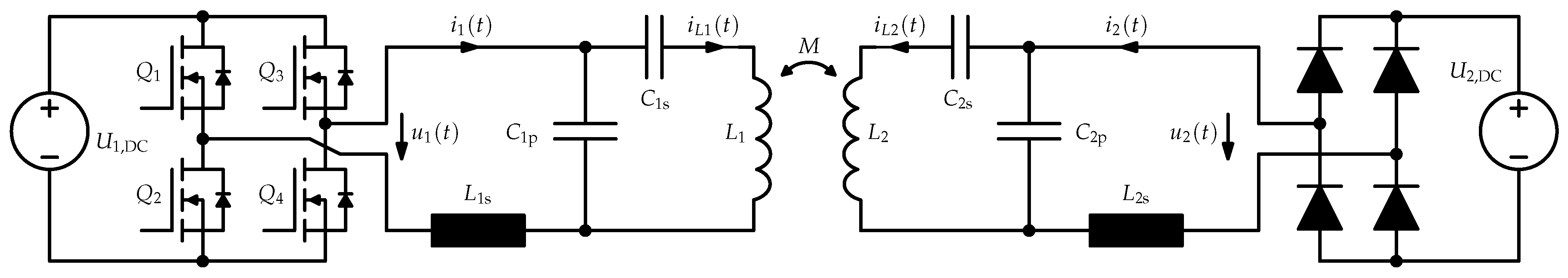
In this section, the fundamentals of inductive power transfer systems with LCC-LCC compensation are explained in more detail. First, systems with one primary coil are considered. The proposed dynamic wireless power transfer (DWPT) system uses an LCC-LCC-compensated wireless power transfer path. An electric circuit of a conventional one-to-one system is shown in Figure 1. The coupled coils are illustrated in an abstracted manner. Basic principles for the magnetic and electrical modeling of coupled coils are outlined in [21,22,23].
Major benefits include the constant current behavior at the load side and its immunity to a decoupling of the coil system ( k = 0 ). Furthermore, this compensation configuration provides a rather steady efficiency for misaligned coils [24]. This makes LCC-LCC-compensated systems well suited for dynamic charging of electrical vehicles. A detailed derivation of the system’s behavior is given in [25,26]. Usually, the primary and secondary resonant tanks are designed to match the system’s design resonant frequency
ω d = 1 L 1 s C 1 p = 1 L 2 s C 2 p .
In case of automotive application, the frequency is normally in the range of 85 kHz. The remaining design criteria for the transfer path’s components are given in (2) and (3).
L 1 s = α 1 L 1 L 2 s = α 2 L 2
C 1 s = 1 ω d 2 L 1 ( 1 α 1 ) C 2 s = 1 ω d 2 L 2 ( 1 α 2 )
The scaling factors α 1 and α 2 can be freely selected in the range 0 < α 1 . For the following studies, a factor of 0.38 was chosen. The wireless power transfer path behaves like a band pass filter matched to ω d . Hence, for excitation only, the fundamental of the inverter output voltage
U 1 = 2 2 π U 1 , DC sin ( D π 2 )
and the rectifier input voltage
U 2 = 2 2 π U 2 , DC 0.9 U 2 , DC
has to be considered. The factor D with 0 D 1 represents the relative pulse when using a symmetric PWM on the primary side. Both currents
I L 1 = U 1 j ω d α 1 L 1 I L 2 = U 2 j ω d α 2 L 2
in the coupled coils are proportional to the corresponding voltage levels U 1 or U 2 . Additionally, there is a constant phase relation between voltage and current that is utilized and is very important for the DWPT system’s concept. With the inverter output and rectifier input current
I 1 = M U 2 ω d α 1 L 1 α 2 L 2 I 2 = M U 1 ω d α 1 L 1 α 2 L 2
and the fundamental voltage levels (4) or (5), the transferred power
P 2 = M U 1 U 2 ω d α 1 L 1 α 2 L 2
can be calculated.

3. Systems with Multiple Primary Coils

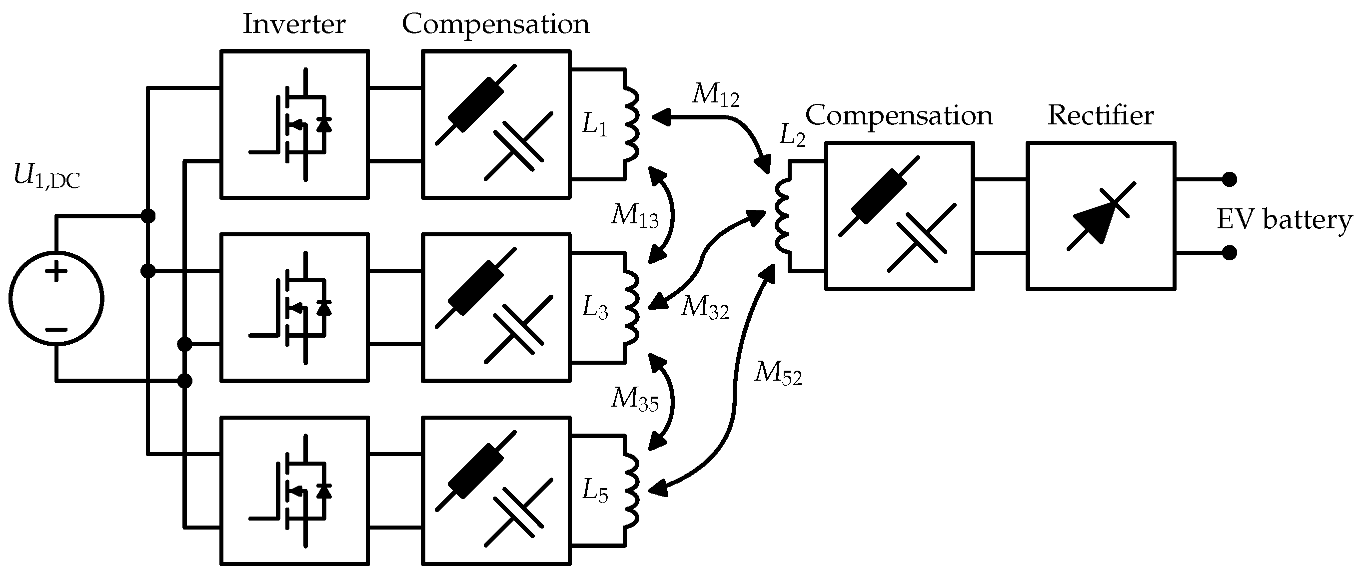
In the following section, the model is extended for use with multiple primary coils. In addition, the arrangement of the coils and the control of the inverters are explained. The proposed DWPT systems consist of numerous straight arranged primary segments outlined in Figure 1. A simplified block diagram with three primary coils and a picture of the resulting system are shown in Figure 2.
Driving the inverters synchronously results in phase primary coil currents according to (7). Consequently, the cumulative transferred power
P 2 = | n = 1 , 3 , 5 , M n 2 U n U 2 ω d α 1 L 1 α 2 L 2 |
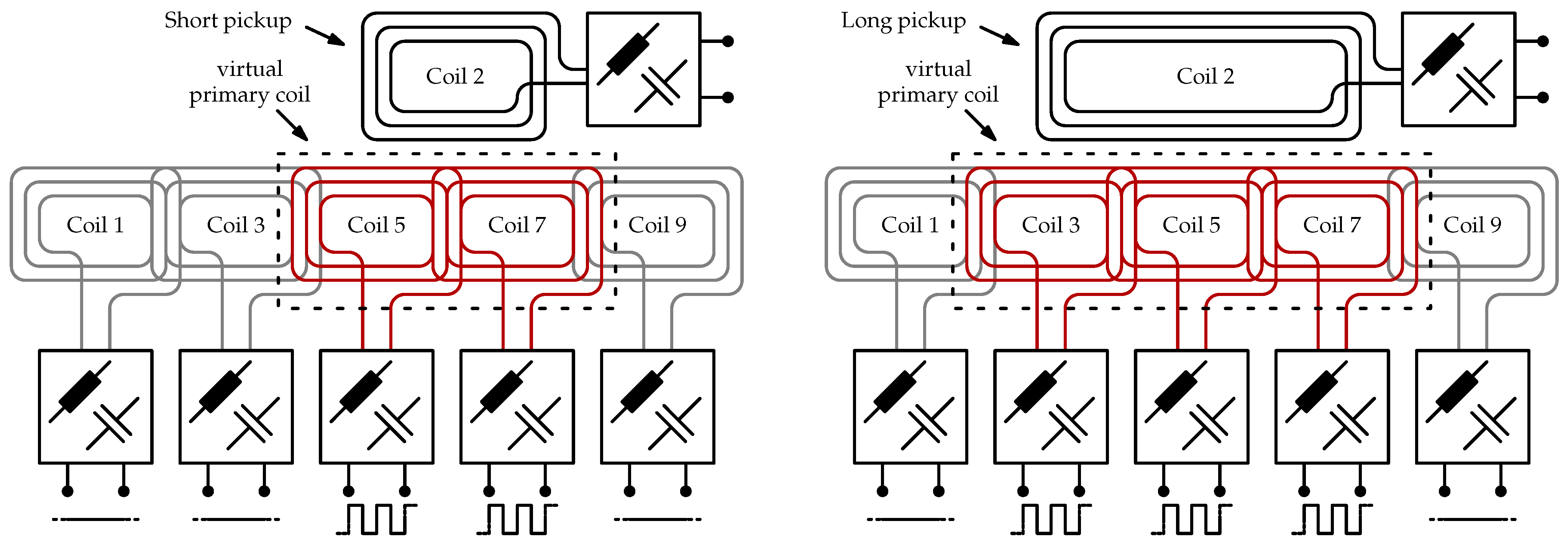
can be expressed as a superposition of all transfer paths. However, an activated primary segment does not necessarily lead to an increased power flow even when it is magnetically coupled to the pickup coil. A negatively coupled and activated primary segment results in a negative power flow from the secondary to the primary side. This effect was verified with measurements. The qualitative illustration of the underlying coupling factor courses is shown afterward. Segments without any magnetic coupling to a pickup should be turned off to reduce losses. This must be performed by shorting the related inverter output. An abstracted schematic of the the coil arrangement and control strategy is shown in Figure 3.
The difference between the left and right configuration illustrates the scalability of the proposed approach. Depending on the pickup length, more or less primary segments are in an active state. Since the coil currents are in phase, the magnetic flux at the coil joints is eliminated, and a longer primary coil is formed. The transferred power can be easily scaled with the pickup coil length.

4. Realization of the DWPT System and Measurement Setup

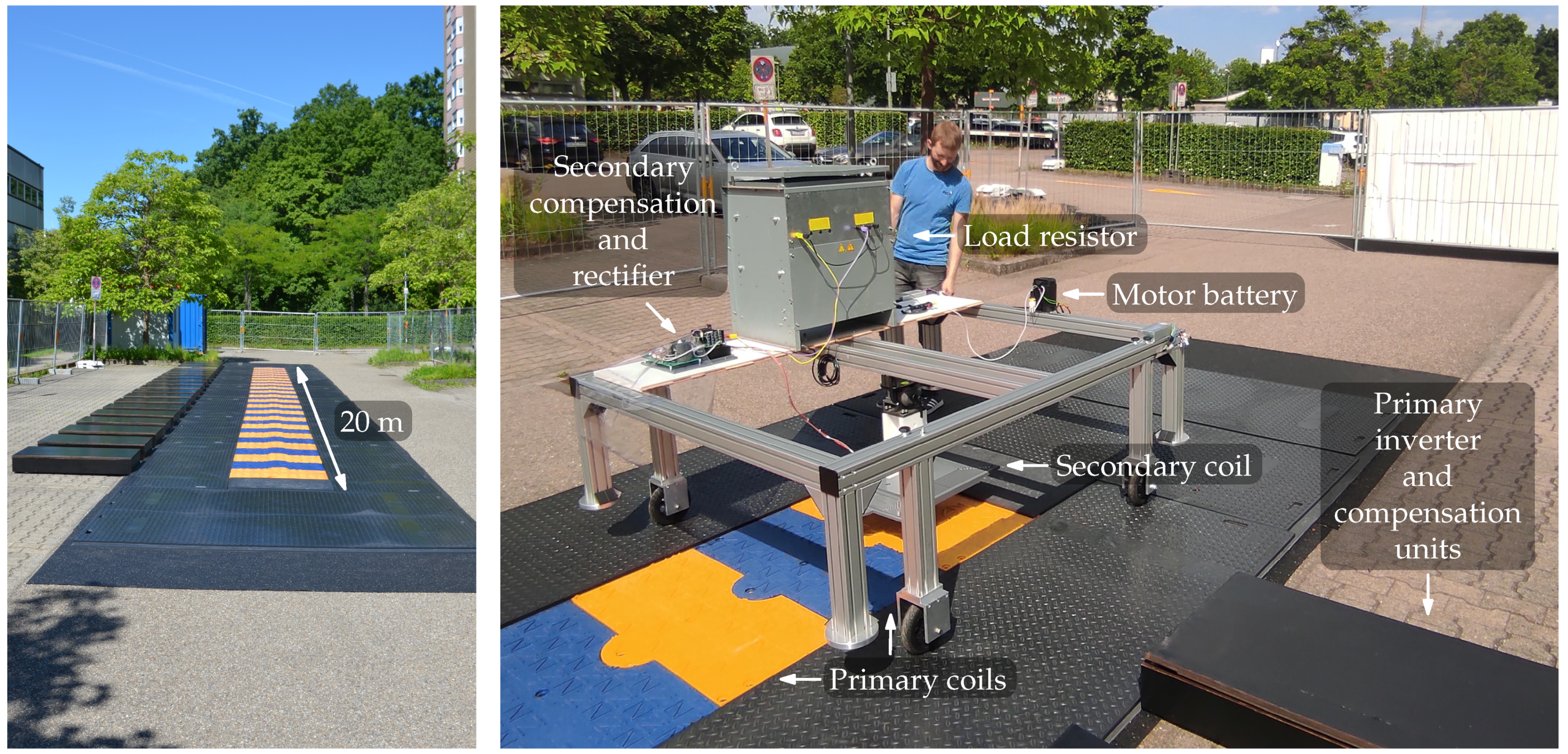
This section describes the design of the DWPT test system. It includes the hardware architecture as well as the functionality of the software used in the inverter units. According to the principle outlined in the previous section, a DWPT test track was built up. An overview of the realized system is given in Figure 4.
To keep the vehicle on the track, a plastic rail (not depicted in Figure 4) on one side of the lane was mounted. This rail guided both left side wheels of the vehicle. For safety reasons and for sufficient clearance between the person and the coil system, the vehicle was electrically driven and remote controlled. The drive motors were supplied by a 36 V battery. A summary of the system’s boundary conditions for the measurements in the following section are given in 
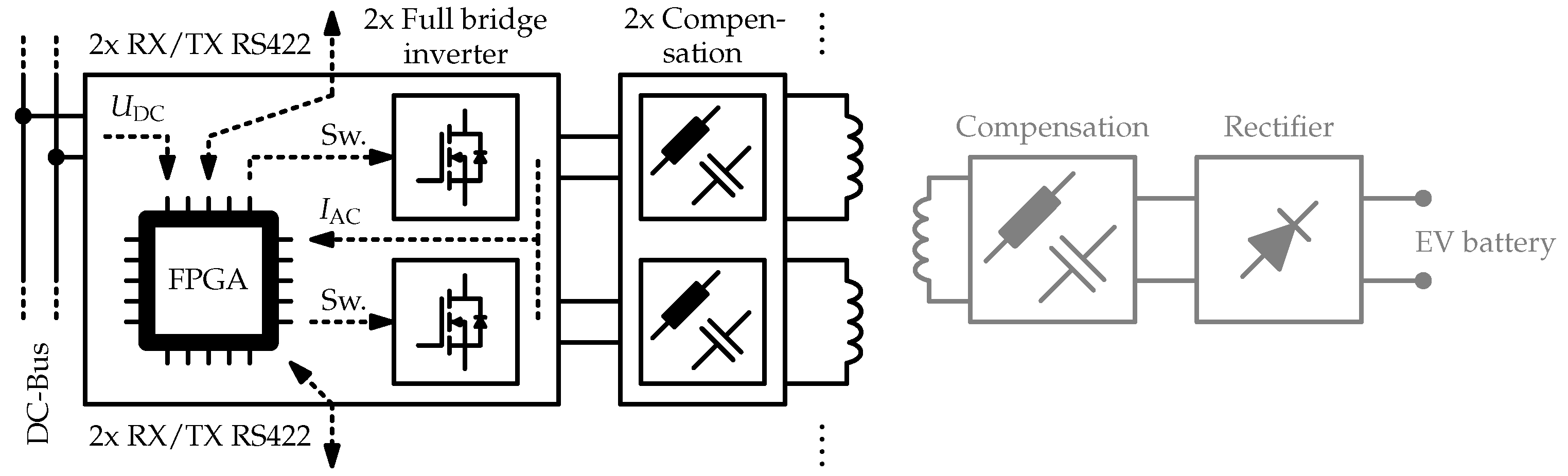
Table 2. The 20 m long test track consists of 40 primary segments connected to 20 inverter and compensation units. Each inverter unit is connected to a compensation unit and supplies two primary segments. A block diagram is depicted in Figure 5.
Any unit is controlled by an FPGA board (Terasic DE0-Nano-SoC), contains two full bridge inverters (8x GeneSiC G3R30MT12K in total) and is supplied by a general DC bus. Both inverter output currents and the DC link voltage are available measurement quantities to the FPGA. Currents are measured with a sampling rate of 10 MSps and 12 bit resolution (2x Analog Devices LTC1420 in total). Since the DC link voltage changes very slowly, it is sampled with 100 kSps but with a higher 16 bit resolution (Analog Devices AD7684). The inverter output voltages
u 1 U 1 , DC ( Q 1 = 0 ; Q 2 = 1 ; Q 3 = 1 ; Q 4 = 0 ) U 1 , DC ( Q 1 = 1 ; Q 2 = 0 ; Q 3 = 0 ; Q 4 = 1 ) 0 V ( Q 1 = 1 ; Q 2 = 0 ; Q 3 = 1 ; Q 4 = 0 ) 0 V ( Q 1 = 0 ; Q 2 = 1 ; Q 3 = 0 ; Q 4 = 1 )
are not acquired but can be reconstructed by means of the DC link voltage and the full bridge switching commands according to (10). Subsequently, the active output power
P 1 = 2 T 0 T / 2 u 1 ( t ) i 1 ( t ) d t 1 N n = 0 N u 1 ( n ) i 1 ( n )
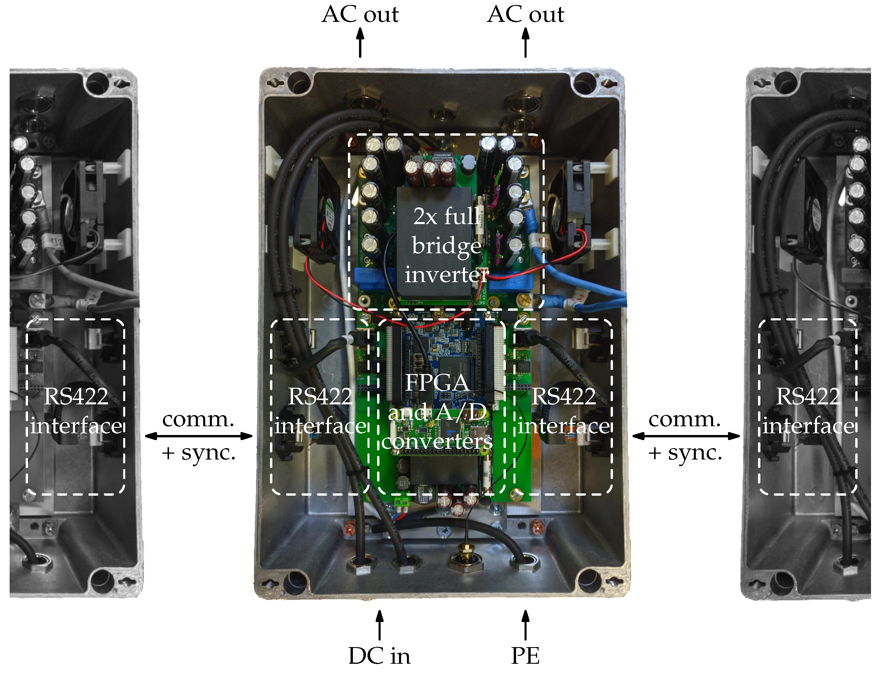
for both full bridge inverters can be calculated two times per full wave. Each inverter unit is equipped with two RS422 communication interfaces used for synchronization and high-level communication to the direct adjacent units. One interface consists of two bidirectional channels. The first channel is used for high-level data transmission such as segment power or state. The other channel is utilized for PWM synchronization in a low level way. A detailed picture of the developed inverter unit is shown in Figure 6.
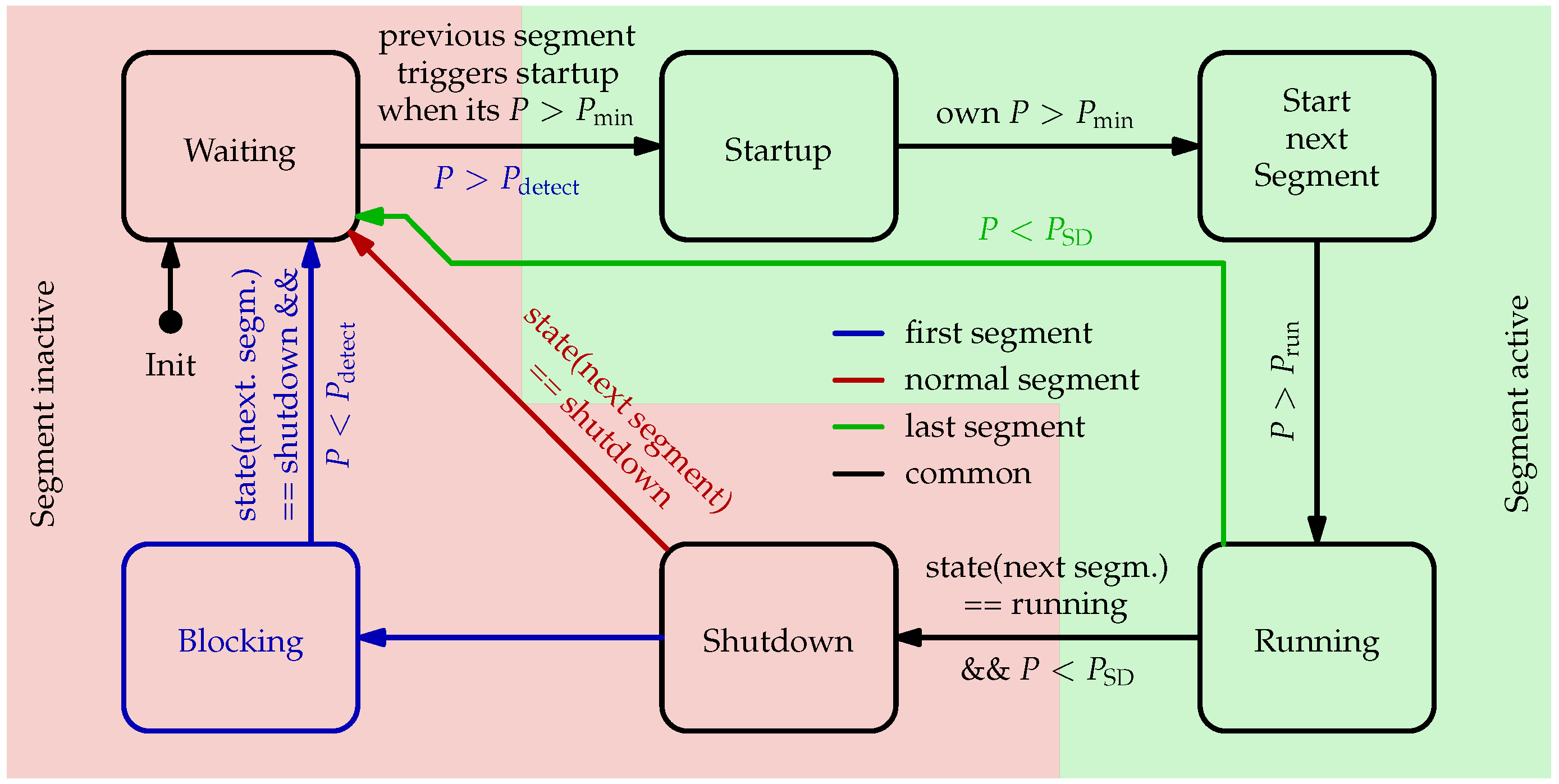
Segment activation and shutdown are controlled by one state machine per segment. A state flow diagram of the underlying state machine is shown in 
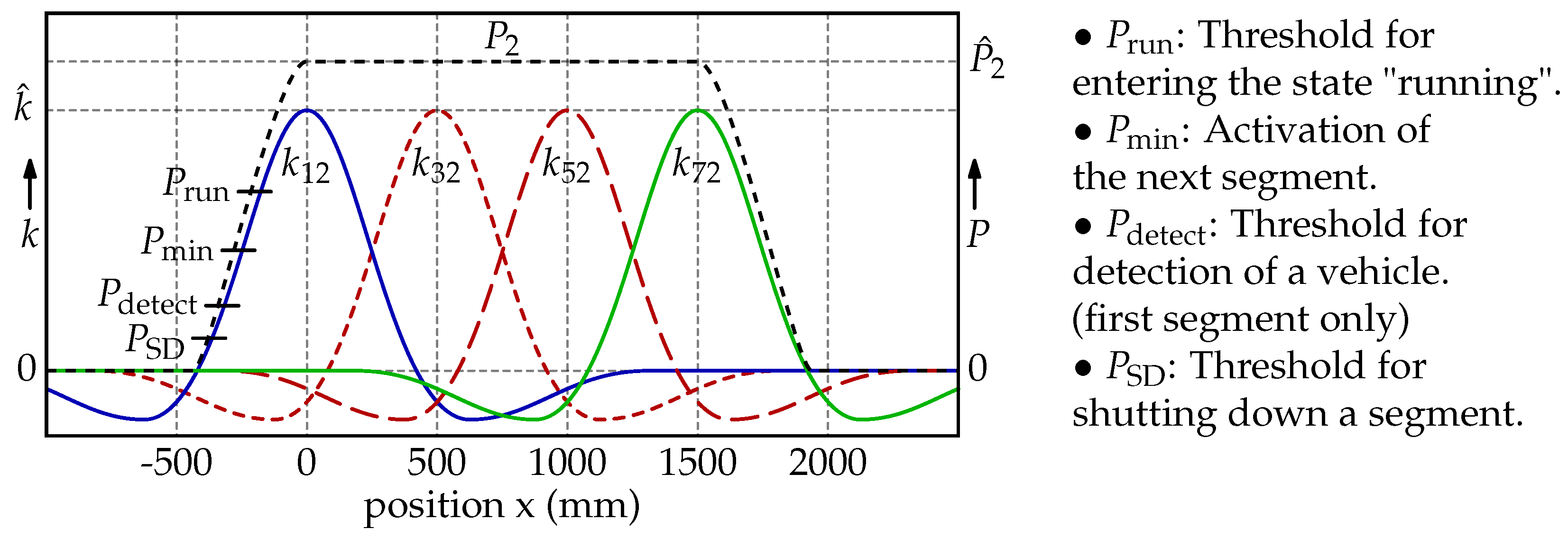
Figure 7. A qualitative illustration of the related power levels besides the courses of the coupling factors and the transferred power is depicted in Figure 8.
Depending on the segment type, the state flow varies at certain points. There are three different types: one first segment at the track’s starting point, followed by several normal segments, and finally one last segment at the track’s tail end. A startup of a normal segment is triggered by the preceding one when its transferred power reaches the level P min . As the first segment has no precursor, it normally runs in an idle state with reduced PWM duty cycle and starts itself when P detect is exceeded. As soon as a segment’s transferred power reaches P run , its state changes to the running state. Subsequently, the coupling factor and transferred power of the regarding segment reach and cross their maximum, and the transferred power decreases afterward (see Figure 8). If the following segment is in the running state and the power drops below P SD , a segment enters the shutdown state. Because the last segment has no successor, only the power condition ( P < P SD ) is sufficient to re-enter the waiting state. Normal segments just reach the waiting state when the following one is shut down. The first segment is additionally blocked after a shutdown in order to avoid an instant reactivation by itself. This mode can only be left if the following segment is shut down and its own transferred power is below P detect .

5. Measurement Results

Following, the measurements obtained with the test system are presented. In addition to the transmitted power and efficiency, the interference between the primary segments and its effect on the inverter currents are considered. To acquire the following results, the pickup vehicle (see Figure 4) was moved over the test track with moderate velocity. The power and efficiency measurements in Figure 9 and Figure 10 were performed with a pickup speed of approximately 0.8 m s . Both primary and secondary power were recorded with a Yokogawa WT1800-E power analyzer. Since only one power meter was used, the secondary DC voltage and current were measured with the aid of a trailing cable. All remaining evaluations were made on the basis of oscilloscope recordings and an elevated pickup speed of about 2 m s . Here, an Yokogawa DLM4038 eight channel oscilloscope, current clamps and differential voltage probes were utilized. An overview of the system’s parameters is shown in Table 2.
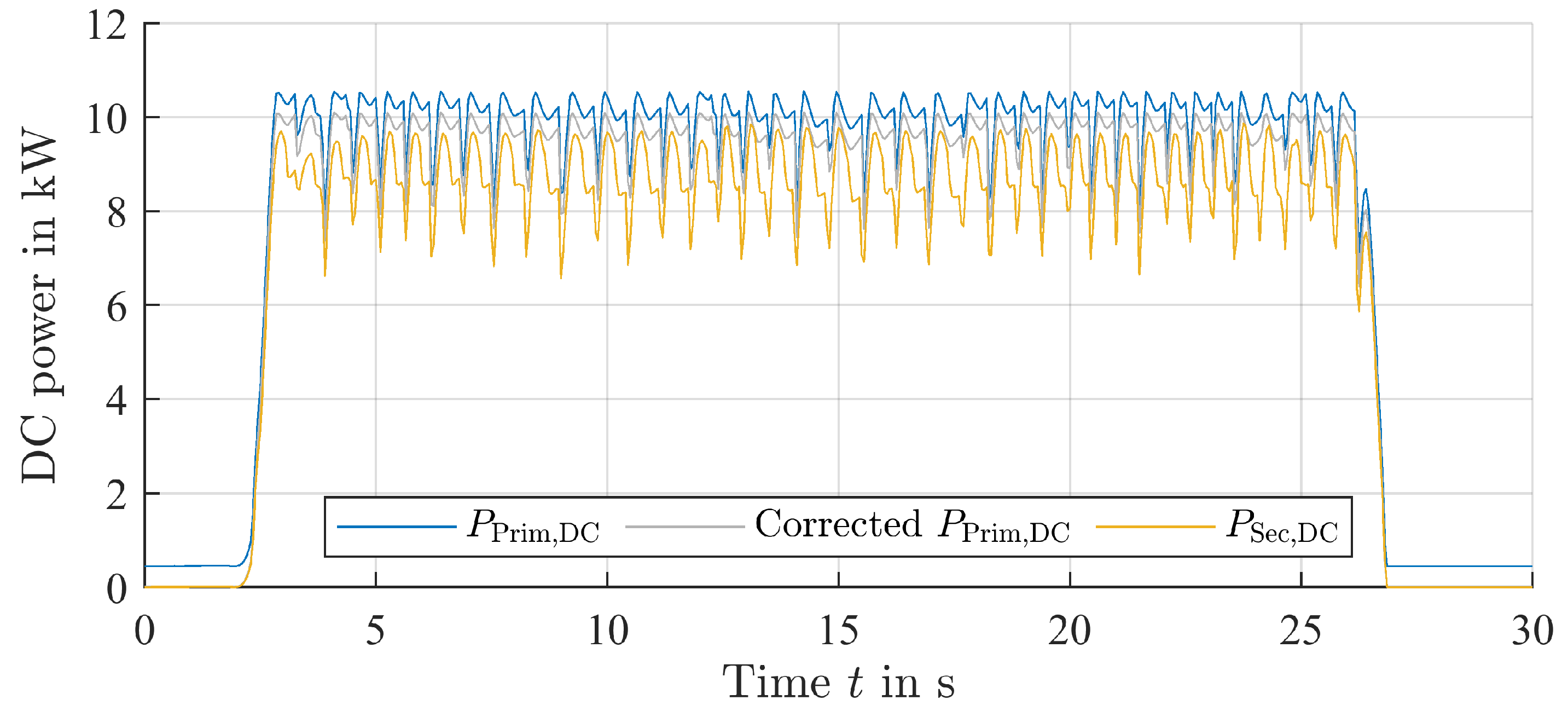
Figure 9 shows the primary and secondary DC power P Prim , DC and P Sec , DC while the pickup moves over the entire test track. The system’s overall idle power is fairly high by reason of the modular research friendly design and the idling first segment. Both reasons have little practical relevance. The pickup approximation detection should later be realized with dedicated high-frequency coils. Additionally, a monolithic controller and power electronics design allow for massively reduced idle power consumption. Thus, a corrected primary power P Prim , DC that neglects the idle consumption was derived. Primary inverter, rectifier, compensation and coil losses are nevertheless included in the corrected power.
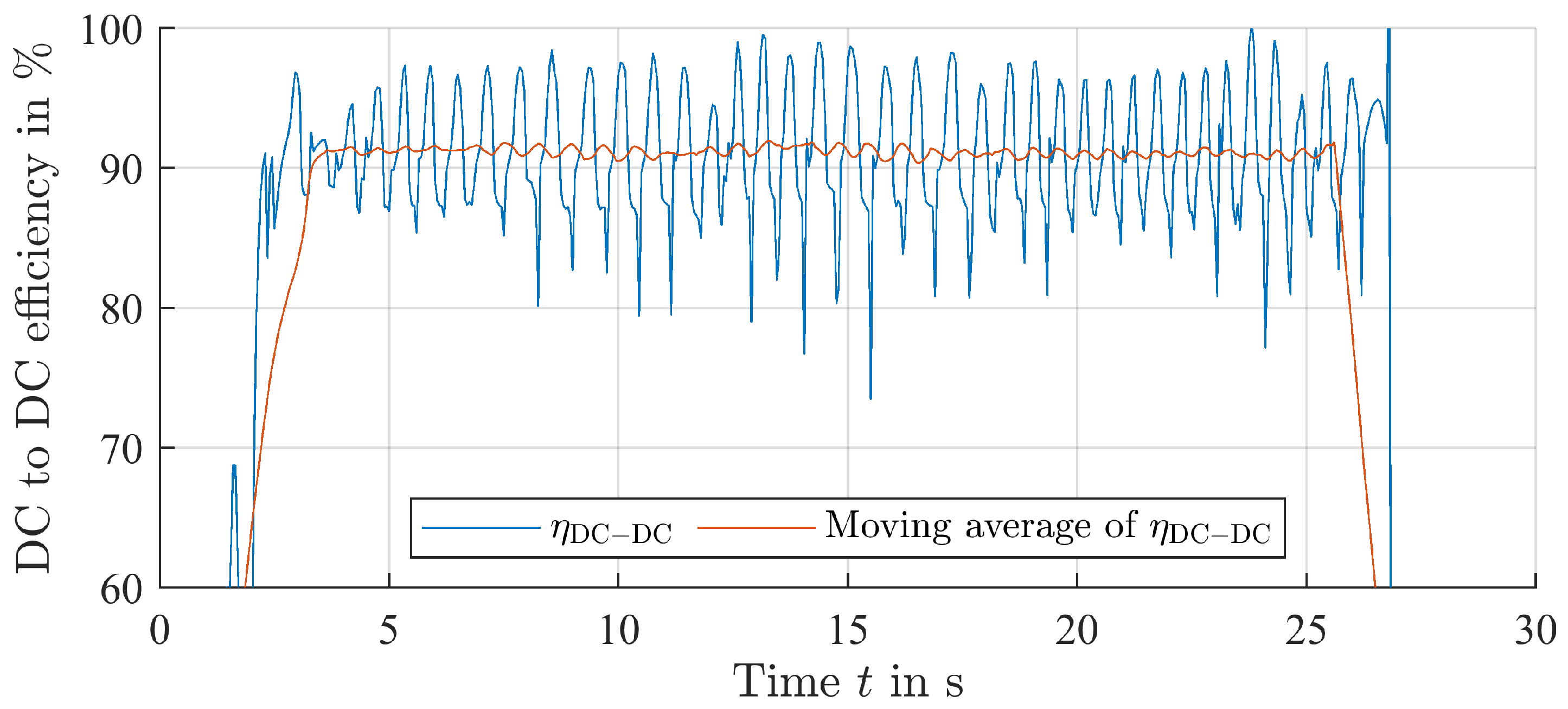
The DC to DC efficiency rests on the corrected primary and secondary DC powers, which are shown in Figure 10. For a better readability, the course was additionally smoothed with a moving average filter. Over the relevant range, an efficiency of approximately 91 to 92% was achieved. The high variation in the efficiency is presumably caused by the large distributed DC link capacitance. Energy stored in the inverter-integrated capacitors is not recognized immediately, because the power meter is connected to the DC bus entry point. Fast power demand changes of the inverters are initially evened out by the distributed DC link capacitors, which leads to a lag in the primary power recordings, whereas the transferred power on the secondary side is recorded with no or neglectable delay.
Due to a 20 Hz acquisition rate limitation of the Yokogawa WT1800-E power analyzer, the above shown results are very course. To obtain a power course with a more precise time resolution, additional surveys based on oscilloscope recordings were performed. In this case, a sample rate of 12.5 MSps was chosen, which allowed for a 2 s logging time for all eight channels. Two segments in the middle region of the test track were surveyed with an elevated pickup speed of 2 m s . The measured quantities were the primary DC voltage and current, both inverter output voltages and currents, and both primary coil currents. All following results are derived from the mentioned quantities. 
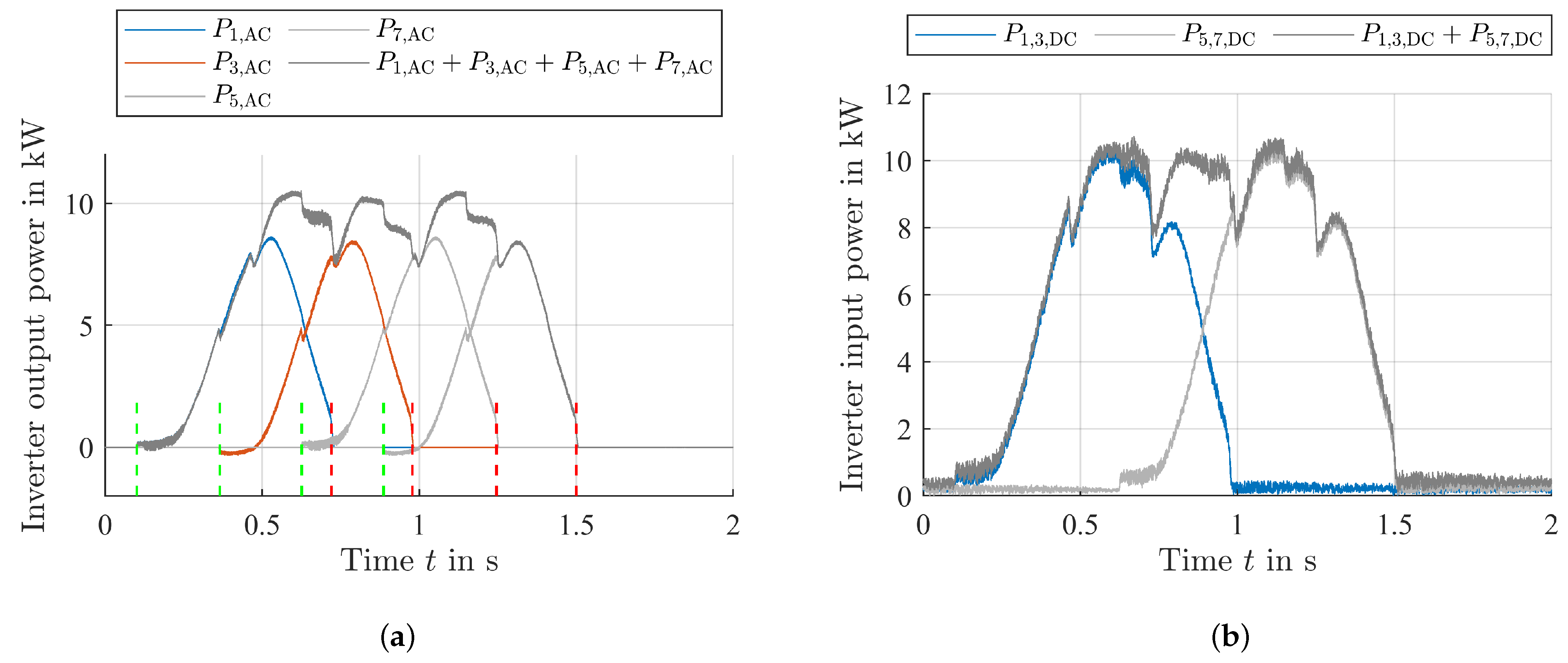
Figure 11 shows the DC input power P 1 , 3 , DC and AC output powers P 1 , AC and P 3 , AC of one inverter unit.
P ( k ) 1 M n = k k + M 1 u ( n ) i ( n ) M = 10 · f sample f d = 1471 , t = k f sample
For better insight, the courses of the two following segments P 5 , AC , P 7 , AC and P 5 , 7 , DC were reconstructed from the original measurements and are marked light gray. The total drawn and drain power is marked in dark gray. Startups and shutdowns of segments are flagged with dotted green and red lines. The pickup power fluctuation is approximately 25% with on average 2.37 activated segments. If a more constant power flow is required, the transmitted power can be regulated by an additional DC-DC converter or active rectifier on the secondary side. However, since the traction battery will be used as an energy buffer in battery electric vehicles, a constant power flow is not necessary in this use case. The current algorithm (see Figure 7) of a segment’s startup is comparatively early in the range of a negative coupling factor. Later startups should have no negative effect on the power flow. However, a higher trigger threshold P min leads to a less robust system behavior in case of pickup misalignments.
The following section focuses on the inverter output quantities. For best presentability, currents and voltages were transformed from the time domain into the frequency domain via fast Fourier transform (FFT). FFT was applied block-wise for ten WPT system periods. Figure 12 shows the amplitude spectrum of the inverter output currents of two adjacent segments.
The frequency range is 500 kHz in order to visualize the current up to the fifth harmonic. Segment startups and shutdowns are flagged as green and red, respectively. Marks related to the regarded segment are solid. Dotted and dashed lines relate to directly adjoining segments and segments with a distance of at least two. A segment’s current fundamental is heavily influenced by directly adjoining segments due to a high primary-to-primary coupling ( k = 0.086 ). An activated adjacent segment leads to a significant current amplitude increase (best visibility in Figure 12b). Harmonics in the currents are generated by their own inverter.
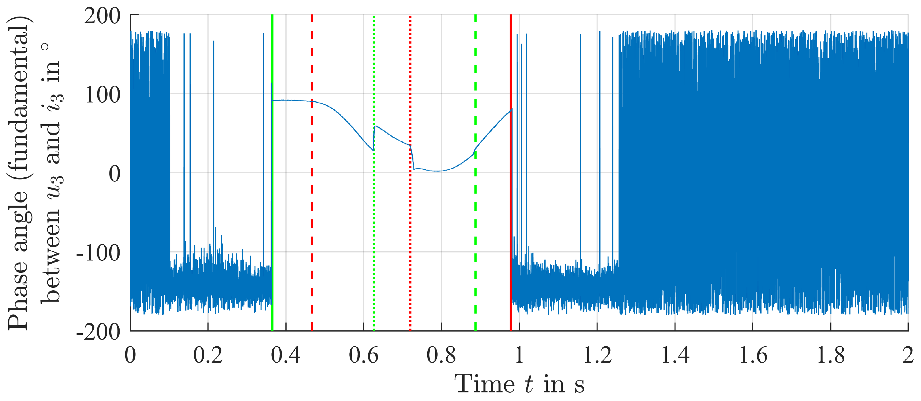
Figure 13 depicts the phase angle between the inverter output voltage and current fundamentals of the second examined segment.
φ = U ̲ 3 , ω d I ̲ 3 , ω d
The startup and shutdown marks are comparable to those in Figure 12. The phase angle is only valuable while the regarded segment is activated due to an absence of voltage phase information when the inverter output is shorted. Directly neighbored activated segments lead to significantly increased phase shift between the fundamental’s voltage and current. Generally, a pretty large phase shift can be observed in the span of operation time, as there is at least one activated directly adjoining segment.
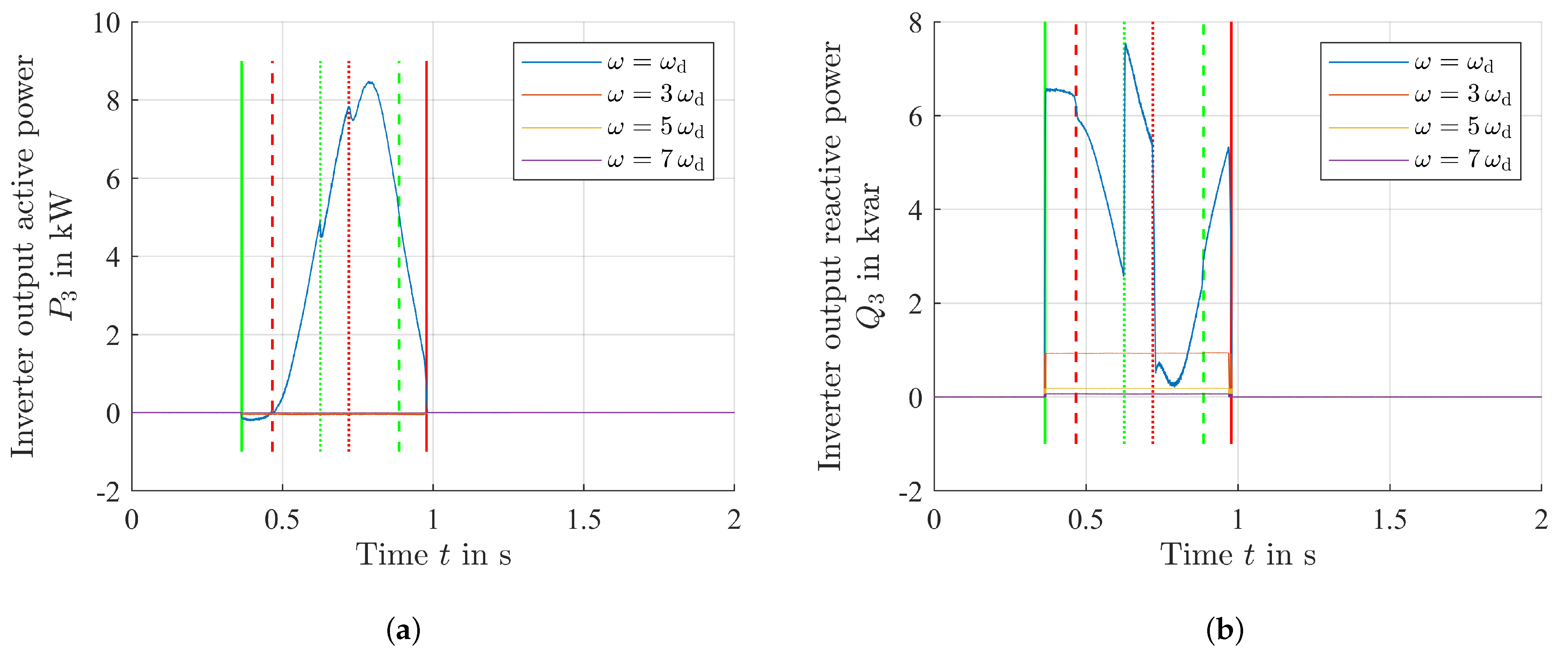
Figure 14b shows the inverter’s reactive output power from the fundamental to the seventh harmonic and clarifies this impact.
P ( ω ) = U ̲ 3 , ω I ̲ 3 , ω * , ω = ω d , 3 ω d , 5 ω d , 7 ω d
Multiple activated and coupled segments lead to an elevated reactive power requirement at the corresponding inverter outputs. However, the reactive powers in the harmonics are constant and negligible compared to the fundamental. The fundamental’s active power course derived from the FFT (see Figure 14a) matches to that shown in Figure 11a.
Q ( ω ) = U ̲ 3 , ω I ̲ 3 , ω * , ω = ω d , 3 ω d , 5 ω d , 7 ω d
Due to the harmonics’ phase angle of approximately 90°, these are not involved in active power transfer.
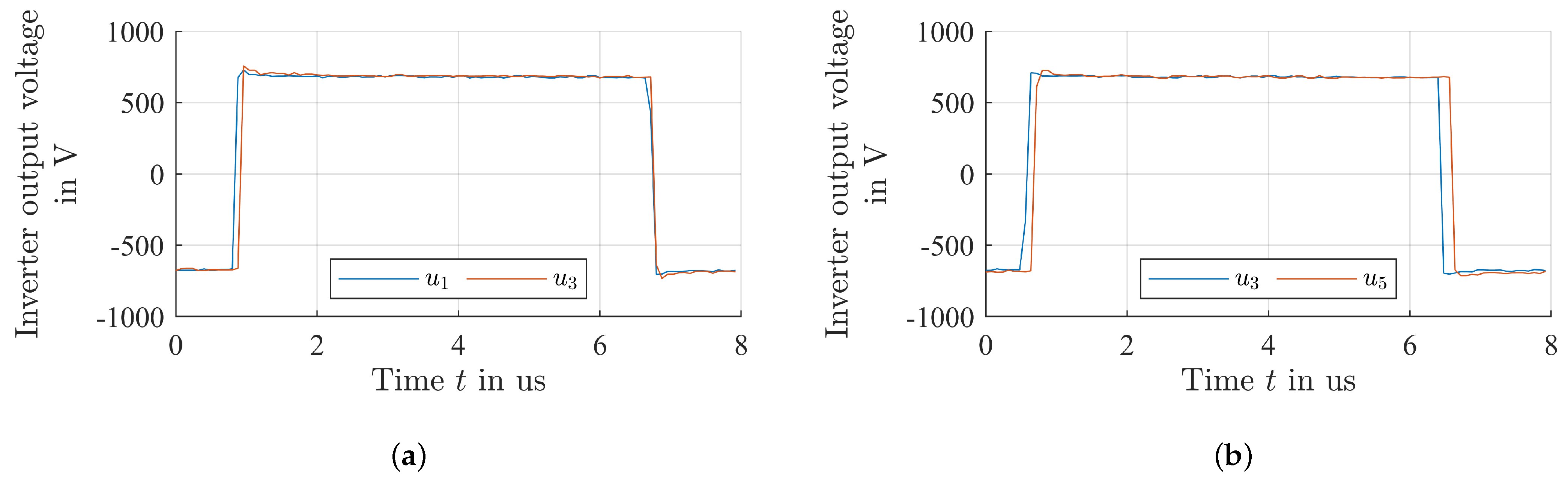
Finally, the voltage phase shift between two successive inverter outputs was evaluated. A good synchronization is important in case of larger pickups that cover multiple primary coils. Figure 15a shows the voltage courses of both inverters within one unit for a half wave. A delay of 40 ns was measured that leads to a 1.22° phase shift. Figure 15b depicts the same measurement for the delay between two inverter units. Between the second output of the first and the first output of the second evaluated inverter, a 140 ns delay or, respectively, 4.28° phase shift was measured. These phase shifts would not significantly affect the power transfer to larger pickup coils.

6. Discussion

The described setup was designed as a test system for further investigations on DWPT systems. The arrangement of the inverter and compensation offers a very high flexibility and is not designed under the aspect of cost optimization. The presented concept for a DWPT system meets the requirement for seamless energy flow in conjunction with circular coils. With the low power ripple achieved, the utilization of this concept is also possible in applications with very small energy storage. The current design of compensation and primary coils still results in a significant reactive power consumption at the inverter outputs of the active segments. At this point, further optimizations are useful to reduce the load on the inverters. Starting points to achieve this are, for example, the reduction of the primary to primary coupling and an adjustment of the primary side compensation. A lower cross-coupling between the primary coils would reduce inverter and compensation losses. A way to achieve this could be a longer and more narrow primary coil design. However, this results in a drawback in primary to secondary coupling for short pickup coils. A spacial separation of the coils is not possible in connection with this approach and only one pickup pad, as this would lead to power transmission drops in the area of segment transitions.

7. Conclusions

Dynamic wireless power transfer is gaining increasing attention in research and development of various application areas. In this work, a dynamic energy transfer system for electric vehicles was investigated. To demonstrate continuous energy transfer, a 20 m long inductive charging track was designed and constructed. The track consisted of 40 individual coil elements with a footprint of 0.5 by 0.39 m. The nominal distance between the coils on the primary side, which represent the track on the road, and the secondary pick up coils was chosen to be 20 cm copper to copper. The primary coils are arranged in a way that they overlap to obtain a constant energy transfer with a low ripple. The position of the vehicle above the coil system is automatically detected, and only the relevant primary coils in the ground are energized at any time. Every primary coil has its own inverter and compensation network. The inverter logic is based on a FPGA to handle fast sampling times and safety critical events in real time. On the secondary side, a passive rectifier and a compensation network were used. The transferred power can be adjusted proportionally to the coil area on the secondary side. A power of 10 kW was continuously transmitted with an overall efficiency of approximately 91%. Finally, it was investigated how the individual primary elements influence each other due to their high coupling. A negative influence of the primary elements on each other was determined.

Author Contributions

Conceptualization, J.N., N.P. and L.E.; Data curation, J.N.; Formal analysis, J.N. and L.E.; Funding acquisition, N.P.; Investigation, J.N. and L.E.; Methodology, J.N. and L.E.; Project administration, J.N. and N.P.; Resources, N.P.; Software, J.N. and L.E.; Supervision, N.P.; Validation, J.N. and L.E.; Visualization, J.N.; Writing—original draft, J.N. and N.P.; Writing—review and editing, N.P. and L.E. All authors have read and agreed to the published version of the manuscript.

Funding

This research was funded by Ministerium für Wissenschaft, Forschung und Kunst Baden-Württemberg.

Data Availability Statement

Not applicable.

Conflicts of Interest

The funders had no role in the design of the study; in the collection, analyses, or interpretation of data; in the writing of the manuscript; or in the decision to publish the results.

References

  1. Yang, H.; Wu, C.; Chen, T. Efficiency Improvement for Wireless Power Transfer System via a Nonlinear Resistance Matching Network. Electronics 2023, 12, 1341. [Google Scholar] [CrossRef]
  2. Maemura, M.; Wendt, A. Dynamic Power Transfer as a Feature—Employing Stationary WPT Devices for Dynamic Operation. In Proceedings of the 2020 IEEE PELS Workshop on Emerging Technologies: Wireless Power Transfer (WoW), Seoul, Republic of Korea, 15–19 November 2020; pp. 50–55. [Google Scholar] [CrossRef]
  3. From Wireless to Dynamic Electric Vehicle Charging: The Evolution of Qualcomm Halo. Available online: https://www.qualcomm.com/news/onq/2017/05/wireless-dynamic-ev-charging-evolution-qualcomm-halo (accessed on 2 May 2023).
  4. Wireless Charging Electric Road Projects|Electreon. Available online: https://electreon.com/projects (accessed on 2 May 2023).
  5. Standard For Industrial Wireless Charging|Wireless Power Consortium. Available online: https://www.wirelesspowerconsortium.com/industry/ (accessed on 2 May 2023).
  6. Galizzi, M.; Caldara, M.; Re, V.; Vitali, A. A novel Qi-standard compliant full-bridge wireless power charger for low power devices. In Proceedings of the 2013 IEEE Wireless Power Transfer (WPT), Perugia, Italy, 15–16 May 2013; pp. 44–47. [Google Scholar] [CrossRef]
  7. SAE Standard J2954; Wireless Power Transfer for Light-Duty Plug-In/Electric Vehicles and Alignment Methodology. SAE International: Warrendale, PA, USA, 2020.
  8. Kumar, K.; Gupta, S.; Nema, S. A review of dynamic charging of electric vehicles. In Proceedings of the 2021 7th International Conference on Electrical Energy Systems (ICEES), Virtual, 11–13 February 2021; pp. 162–165. [Google Scholar] [CrossRef]
  9. Nimri, R.M.; Kamineni, A.; Zane, R. A Modular Pad Design compatible with SAE J2954 for Dynamic Inductive Power Transfer. In Proceedings of the 2020 IEEE PELS Workshop on Emerging Technologies: Wireless Power Transfer (WoW), Seoul, Republic of Korea, 15–19 November 2020; pp. 45–49. [Google Scholar] [CrossRef]
  10. IPT® Floor 20 kHz. Available online: https://ipt-technology.com/product-ipt-floor-20khz/ (accessed on 2 May 2023).
  11. Ean, K.K.; Kai, S.; Sukprasert, P.; Imura, T.; Hori, Y. Two-transmitter wireless power transfer with LCL circuit for continuous power in dynamic charging. In Proceedings of the IEEE PELS Workshop on Emerging Technologies: Wireless Power (WoW), Daejeon, Republic of Korea, 5–6 June 2015; pp. 1–6. [Google Scholar] [CrossRef]
  12. Diep, N.T.; Trung, N.K.; Minh, T.T. Power Control in the Dynamic Wireless Charging of Electric Vehicles. In Proceedings of the 2019 10th International Conference on Power Electronics and ECCE Asia (ICPE 2019 - ECCE Asia), Busan, Republic of Korea, 27–30 May 2019; pp. 1–6. [Google Scholar] [CrossRef]
  13. Laporte, S.; Coquery, G.; Deniau, V.; Bernardinis, A.D.; Hautière, N. Dynamic Wireless Power Transfer Charging Infrastructure for Future EVs: From Experimental Track to Real Circulated Roads Demonstrations. World Electr. Veh. J. 2019, 10, 84. [Google Scholar] [CrossRef]
  14. Galigekere, V.; Ozpineci, B. High Power and Dynamic Wireless Charging of Electric Vehicles (EVs). In Proceedings of the 2021 U.S DOE Vehicle Technologies Office Annual Merit Review, Virtual, 21–25 June 2021. [Google Scholar]
  15. Suul, J.A.; Guidi, G. Overview and Electro-Technical Evaluation of the State-of-the-Art for Conductive and Inductive Power Transfer Technologies. SINTEF Energy Research Report. 2018. Available online: https://www.sintef.no/globalassets/project/elingo/18-0733-rapport-3-technology-for-dynamic-on-road-6-til-nett.pdf (accessed on 2 May 2023).
  16. Bombardier’s PRIMOVE E-buses Pass 500,000 km Milestone. Available online: https://bombardier.com/en/media/news/bombardiers-primove-e-buses-pass-500000-km-milestone (accessed on 2 May 2023).
  17. Thai, V.X.; Choi, S.Y.; Choi, B.H.; Kim, J.H.; Rim, C.T. Coreless power supply rails compatible with both stationary and dynamic charging of electric vehicles. In Proceedings of the 2015 IEEE 2nd International Future Energy Electronics Conference (IFEEC), Taipei, Taiwan, 1–4 November 2015; pp. 1–5. [Google Scholar] [CrossRef]
  18. Choi, S.Y.; Rim, C.T. Recent progress in developments of on-line electric vehicles. In Proceedings of the 2015 6th International Conference on Power Electronics Systems and Applications (PESA), Hong Kong, China, 15–17 December 2015; pp. 1–8. [Google Scholar] [CrossRef]
  19. Xue, L.; Galigekere, V.; Su, G.J.; Zeng, R.; Mohammad, M.; Gurpinar, E.; Chowdhury, S.; Onar, O. Design and Analysis of a 200 kW Dynamic Wireless Charging System for Electric Vehicles. In Proceedings of the 2022 IEEE Applied Power Electronics Conference and Exposition (APEC), Houston, TX, USA, 20–24 March 2022; pp. 1096–1103. [Google Scholar] [CrossRef]
  20. Noeren, J.; Elbracht, L.; Parspour, N.; Wörner, M.; Spindler, M. An Easily Scalable Dynamic WPT System for EVs. In Proceedings of the 2022 Wireless Power Week (WPW), Bordeaux, France, 5–8 July 2022; pp. 482–486. [Google Scholar] [CrossRef]
  21. Heinrich, J.; Parspour, N. Contribution to the development of positioning tolerant inductive charging systems. In Proceedings of the 2010 Emobility - Electrical Power Train, Leipzig, Germany, 8–9 November 2010; pp. 1–5. [Google Scholar] [CrossRef]
  22. Parspour, N.; Maier, D.; Böttigheimer, M. Contactless energy transfer for charging electric and hybrid electric vehicles. In Proceedings of the 30th International Electric Vehicles Symposium and Exhibition, Stuttgart, Germany, 9–11 October 2017; pp. 3154–3161, ISBN 978-1-5108-6370-5. [Google Scholar]
  23. Maier, D.; Heinrich, J.; Zimmer, M.; Maier, M.; Parspour, N. Contribution to the System Design of Contactless Energy Transfer Systems. IEEE Trans. Ind. Appl. 2019, 55, 316–326. [Google Scholar] [CrossRef]
  24. Li, W.; Zhao, H.; Deng, J.; Li, S.; Mi, C.C. Comparison Study on SS and Double-Sided LCC Compensation Topologies for EV/PHEV Wireless Chargers. IEEE Trans. Veh. Technol. 2016, 65, 4429–4439. [Google Scholar] [CrossRef]
  25. Khalilian, M.; Guglielmi, P. Primary-Side Control of a Wireless Power Transfer System with Double-Sided LCC Compensation Topology for Electric Vehicle Battery Charging. In Proceedings of the 2018 IEEE International Telecommunications Energy Conference (INTELEC), Turin, Italy, 7–11 October 2018; pp. 1–6. [Google Scholar] [CrossRef]
  26. Elbracht; Lukas; Noeren, J.; Parspour, N. A Wireless Multicoil Charging System for Low-Voltage Electric Vehicle Applications. World Electr. Veh. J. 2021, 12, 172. [Google Scholar] [CrossRef]
Figure 1. Electric circuit of a LCC-LCC-compensated WPT system with full bridge inverter and passive rectifier.
Energies 16 03936 g001
Figure 2. Block diagram of an LCC-LCC-compensated CET system with three primary modules according to Figure 1 and one secondary pickup [20].
Energies 16 03936 g002
Figure 3. Primary coil arrangement with overlap helps to create a moving virtual coil underneath the pickup coil [20]. Driving the primary inverters in phase leads to magnetic field cancellation at the primary coils’ joints. All remaining inverters have to be shorted. Left: Exemplary coil activation pattern for a short secondary coil. Right: Exemplary coil activation pattern for a long secondary coil.
Energies 16 03936 g003
Figure 4. Dynamic WPT test track with electrically driven pickup vehicle.
Energies 16 03936 g004
Figure 5. Block diagram of inverter unit with controller and compensation unit for two primary segments [20]. Each inverter unit is controlled by one FPGA. Measured quantities: DC link voltage and the inverters’ output current. The RS422 interfaces ensure a communication channel to the adjacent inverter units.
Energies 16 03936 g005
Figure 6. Inverter module includes two full bridge inverters, an FPGA along with AD converters for current and voltage measurement and RS422 interfaces [20]. Adjacent modules are illustrated on the left and right side.
Energies 16 03936 g006
Figure 7. Diagram of the state machine used for each segment (two segments per inverter unit) [20]. Depending on the segment type (first, normal or last segment), different transitions are valid. Special transition and state types for a specific segment type are highlighted in color. Unmarked states and transitions are valid for all remaining segment types. All transitions depend only on segment states and power levels.
Energies 16 03936 g007
Figure 8. Qualitative course of the primary to secondary coupling factors ( k 12 to k 72 ) in the case of four primary coils and the intended course of transferred power ( P 2 ) [20]. The power thresholds used for the controllers state machine are depicted on the left hand side. Thresholds are not true to scale.
Energies 16 03936 g008
Figure 9. DC input and output power of the dynamic WPT system depending on evaluation time. With the corrected primary power, the system’s idle power consumption is neglected.
Energies 16 03936 g009
Figure 10. The dynamic WPT system’s DC to DC efficiency based the corrected primary power depending on evaluation time. For superior readability, the course was additionally smoothed with a moving average filter.
Energies 16 03936 g010
Figure 11. Primary power flow of four primary segments connected to two inverter modules. Only two segments with one inverter module were analyzed due to oscilloscope channel shortage: P 1 , AC , P 3 , AC and P 1 , 3 , DC . The courses of the two following segments P 5 , AC , P 7 , AC and P 5 , 7 , DC was reconstructed from the original measurements and are marked in light gray. Segment startups and shutdowns are flagged with dotted green and red lines, respectively. (a) Primary AC inverter output power of four concatenated segments. (b) Primary DC inverter input power of two concatenated inverter modules.
Energies 16 03936 g011
Figure 12. FFT amplitude spectrum waterfall diagram of the inverter output currents of two adjacent segments with a 500 kHz frequency range. The most significant fundamental and the 3rd and 5th harmonics are located at 85, 255 and 425 kHz. Segment startups and shutdowns are flagged as green and red, respectively (continuous lines for the surveyed segment, dotted lines for directly adjoining segments, and dashed lines for segments with a distance of at least two). (a) First surveyed segment. (b) Following segment in the direction of travel.
Energies 16 03936 g012
Figure 13. Phase angle between inverter output voltage and current fundamentals of the second surveyed segment. The course was acquired by means of an FFT. Segment startups and shutdowns are as flagged green and red, respectively, (continuous lines for the surveyed segment, dotted lines for directly adjoining segments, and dashed lines for segments with a distance of at least two). For a deactivated segment, the phase angle is not reconstructable due to a lack of phase information in the voltage signal.
Energies 16 03936 g013
Figure 14. Active and reactive inverter output power of the second surveyed segment. The fundamental and the 3rd, 5th and 7th harmonics were analyzed. Segment startups and shutdowns are flagged as green and red, respectively (continuous lines for the surveyed segment, dotted lines for directly adjoining segments, and dashed lines for segments with a distance of at least two). (a) Inverter output active power. (b) Inverter output reactive power.
Energies 16 03936 g014
Figure 15. Inverter output voltages of two directly adjoining primary segments. Time delay is approximately 40 ns within one inverter unit and 140 ns between two units. (a) Delay within one inverter unit: ≈40 ns. (b) Delay between two inverter units: ≈140 ns.
Energies 16 03936 g015
Table 2. System parameters for measurements.
ParameterValue
Primary DC link voltage U 1 , DC 680 V
Secondary DC link voltage U 2 , DC ≈680 V
Primary air coil inductance L 1 , 3 , 5 , 81.5 µH
Secondary air coil inductance L 2 81.5 µH
Primary coil effective length50 cm
Primary coil effective width39 cm
Primary coil overlap11 cm
Secondary coil effective length50 cm
Secondary coil effective width39 cm
Design resonant frequency f d 85 kHz
Ratio α 1 0.38
Ratio α 2 0.38
Peak primary to secondary coupling factor k ^ 0.195
Primary to primary coupling factor k pp −0.086
Target output power P ^ 2 10 kW
Air gap track to pickup17 cm
Air gap copper to copper20 cm
Disclaimer/Publisher’s Note: The statements, opinions and data contained in all publications are solely those of the individual author(s) and contributor(s) and not of MDPI and/or the editor(s). MDPI and/or the editor(s) disclaim responsibility for any injury to people or property resulting from any ideas, methods, instructions or products referred to in the content.

