Article

From Hydrometeor Size Distribution Measurements to Projections of Wind Turbine Blade Leading-Edge Erosion

Department of Earth and Atmospheric Sciences, Cornell University, Ithaca, NY 14853, USA
*
Authors to whom correspondence should be addressed.
Energies 2023, 16(9), 3906; https://doi.org/10.3390/en16093906
Submission received: 28 February 2023 / Revised: 26 April 2023 / Accepted: 29 April 2023 / Published: 5 May 2023
(This article belongs to the Topic Advances in Wind Energy Technology)

Abstract

:
Wind turbine blade leading-edge erosion (LEE) is a cause of increased operation and maintenance costs and decreased annual energy production. Thus, detailed, site-specific quantification of likely erosion conditions are critically needed to inform wind plant owner/operator decisions regarding mitigation strategies. Estimating the damage potential at a wind plant site requires accurate measurement of precipitation intensity, phase, droplet size distributions, wind speeds and their joint statistics. The current work quantifies the effect of disdrometer type on the characterization of LEE potential at a site in the US Southern Great Plains. using observations from three co-located disdrometers (an optical, an impact and a video disdrometer), along with hub-height wind-speed observations from a Doppler lidar and two LEE models: a kinetic energy model and the Springer model. Estimates of total kinetic energy of hydrometeor impacts over the four-year study period vary by as much as 38%, and coating lifetime derived from accumulated distance-to-failure estimates from the Springer model differ by an even greater amount, depending on disdrometer type. Damage potential at this site is concentrated in time, with 50% of impact kinetic energy occurring in 6–12 h per year, depending on which set of disdrometer observations is used. Rotor-speed curtailment during the most erosive 0.1–0.2% of 10 min periods is found to increase blade lifetimes and lead to the lowest levelized cost of energy.

1. Introduction

Wind turbine blade leading-edge erosion (LEE) refers to the material loss of wind turbine blade coatings leading to exposure and loss of the laminate. LEE reduces aerodynamic performance and annual energy production (AEP) and is a source of increased operations and maintenance costs [1,2,3,4]. Material loss from the leading edge of the wind turbine blade leads to roughening of the surface, causing reduced aerodynamic efficiency by reducing lift and increasing drag [2]. LEE pattern categorization frequently employs five classes, with Class 1 “small pinholes” exhibiting erosion depth of 0.1–0.2 mm, average feature damage of 2 mm and approximate cord coverage of 3% [3]. Even this level of LEE may result in AEP loss. Maximum lift has been modeled to be negatively impacted for damage associated with roughness heights of 0.11 mm for a rotor with a 175 m diameter [1]. Erosion Classes 3 to 5 (large patches of missing coating, erosion of laminate and complete loss of laminate, respectively), are associated with AEP reductions of 1–5% [5].
Material stresses arising during periods with a large number of hydrometeor impacts on the blades at high closing velocities are thought to be the primary cause of LEE [6,7,8,9]. Accurate descriptions of the hydroclimate, including the precipitation frequency and intensity, plus hydrometeor droplet size distribution (DSD) and phase and fall velocity (vf), are thus critical to LEE estimation and to assessment of the potential benefits of different LEE reduction/mitigation measures. Kinetic energy transfer to rotating blades is highest under the joint occurrence of higher wind speeds and heavier rainfall rates. This is because of the non-linear dependence of blade rotational speed on wind speed. Furthermore, impacts from large hydrometeors disproportionately contribute to material stresses, due to their higher fall velocity (vf) and larger mass [9,10]. Higher rainfall rates (RR, accumulation of water at ground level in a depth-per-time interval) are associated with increased numbers of hydrometeors, mass-weighted mean hydrometeor diameters, and fall velocities [9]. Thus, fidelity is especially important during periods of high RR and high wind speeds. Impacts from hailstones may be particularly important to accumulated material stresses, due to their hardness and large diameter [11,12]. The maximum stress from the impact of a 10 mm hailstone on a WT blade has been shown to be much greater than that from a similarly sized rain droplet with the same closing velocity [13]. As few as five impacts from hailstones with 15–20 mm diameter at a closing velocity of 110 ms−1 caused damage to a glass fiber-reinforced plastic composite coated with polyurethane [14].
Efforts to reduce rates of LEE typically focus on measures to enhance dissipation of the surface, shear and compressional waves generated by hydrometeor impacts. They include application of erosion resistant coatings [15], shields [16] or tapes (typically made of polyurethane and of thickness ~0.3 mm) [17,18]. The primary disadvantages of such approaches are the cost, the potential for the measures to fail (e.g., tapes may become detached or coatings degrade [19]) and/or that the associated modification of the airfoil morphology may lead to aerodynamic performance degradation [20]. An alternative, potentially complementary, approach is the adoption of dynamic wind farm control and, specifically, the implementation of ‘erosion-safe mode’ operation. As the name implies, wind turbine blade rotational speed is reduced during meteorological events that are likely to cause high material stresses [21,22]. This curtailment reduces AEP. It may extend blade lifetimes by reducing material stress, resulting in reduced operations and maintenance costs and yielding net economic benefit to wind farm owner-operators via the reduction in the levelized cost of energy (LCoE) [22].
A range of metrologies are available for detecting size-resolved hydrometeor number concentrations, and in some cases, hydrometeor phase and vf [9]. Ground-based disdrometers generally adopt one of four measurement principles. Two-dimensional video-disdrometers comprise two illumination sources and two video cameras with vertically displaced, but perpendicular, lines of sight. Objects passing through the measurement area obstruct the light and are detected as shadows by the cameras [23,24]. Impact disdrometers record the mechanical force applied when a hydrometeor impacts on the detector [25,26]. Acoustic disdrometers detect the signal generated by hydrometeor impacts on a diaphragm [27]. Optical disdrometers measure hydrometeors as they fall through, and hence break, infrared beams [28]. Active remote sensing technologies, most notably micro-rain radar, also have the potential to provide information about hydrometeor size distributions, phase and vf via backscatter intensity and Doppler shift [29]. Prior research has reported substantial differences in hydrometeor characteristics from these different technologies [9,23,30,31,32]. The measured DSD also exhibit marked deviations from assumed droplet size distributions used for leading-edge erosion experiments within the wind energy industry [9].
Some discrepancies between RR and DSD derived using different disdrometer technologies are inevitable, due to differences in range of hydrometeor diameters detected and/or differences due to the sampling height (in situ disdrometers vs. MRR). However, not all discrepancies are easily attributable to such factors or consistent across studies. For example, past research has found somewhat inconsistent results in comparisons between video disdrometers and version 1 of the OTT Parsivel optical disdrometer considered herein. One study found considerably higher RR from the video disdrometer versus that version of the OTT optical disdrometer (Parsivel (Particle size and velocity), version 1) and that difference in the associated DSD was amplified at higher RR [32]. A second found consistently higher RR and hydrometer number counts from the optical disdrometer, but higher concentrations of hydrometers with D > 4 mm from the video disdrometer [33].
There is also a range of uncertainties associated with the disdrometer detection and sizing of hydrometeors related to: (1) Under-sampling in high wind speeds [34,35,36]. (2) Contamination from insects or debris in the sample volume [35,37]. (3) The small effective field of view and the variation in sampling volume across disdrometers [33,35,38,39]. Of equal or even greater importance are signal processing decisions. These include exclusion of measurements where “droplets” of a given diameter are reported with vf that differ substantially from theoretical estimates of the terminal fall velocity in stagnant air (vt). While it is frequently assumed that vf = vt, this is not always realized. It is critical to ensure that any thresholds used to identify anomalously high or low vf values are carefully selected, because it has profound implications for the number of droplets in each diameter class, N D i and hence the DSD:
N D i = v = 1 x n i , v F t v f i , v Δ D i
where n(i,v) = number count in diameter class i and velocity class v, F = area field of view of the disdrometer, t = sampling interval, vf(i,v) = fall velocity, ΔDi = width of the size class.
A range of thresholds have been used in the literature to screen out disdrometer signals that are erroneous. For example, in one analysis, ‘To improve data quality beyond what the manufacturer’s software provides, drops exceeding ±50% of their theoretical terminal fall speed (Beard 1976) were considered either secondary (i.e., a result of splash) or mismatched drops and eliminated from the dataset, which resulted in an elimination of 8% of the observations’ [32]. A different study excluded data for which v f D v t D B e a r d   0.6 v t D B e a r d [40]. The formulation of v t from Beard implies vt scales with D over all values of D considered, and for D = 0.04 to 6 mm is given by [41]:
v t = v 0 a + b X
where v0 is a constant specified as a function of D. v0 ranges from 4.7 cms−1 for D = 0.04 mm to 914 cms−1 at D = 6 mm. a and b are functions of the elevation of the hydrometeor (atmospheric density and temperature) and X is a function only of hydrometeor diameter. For D = 0.1 mm vt at the ground for standard atmospheric conditions from Equation (2) ~ 0.2 ms−1, for D = 1 mm, vt ~ 3 ms−1, and for D = 6 mm, vt ~ 10 ms−1, which is slightly higher than the approximation of Gunn and Kinzer [42] that is used herein. A further analysis used v f D v t D A t l a s   0.4 v t D A t l a s [43], to exclude erroneous data values. The approximation of Atlas [44] is based on that of Gunn and Kinzer [42] and has the simplified form for a standard atmosphere of:
v t = α 1 α 2 exp 6 D
where D is specified in cm, α1 = 965, α2 = 1030, and these are given in cms−1.
A number of past studies have indicated that the second generation OTT Parsivel optical disdrometer (Parsivel2) considered here may under-estimate D and v f (and thus RR) relative to video disdrometers in conditions with very high RR and strong winds, such as those associated with tropical cyclones [45,46]. The majority of the errors derived from hydrometers with D > 5 mm were reported at unrealistically low vf (< 1 ms−1) when hydrometers impinge upon the viewing area at an angle substantially off zenith. The majority of these errors were reported at near-surface (10-m) wind speeds above 20 ms−1 [46].
A second major decision point in the analysis of disdrometer data relates to assumptions regarding the morphology of the hydrometeors. As liquid hydrometeors fall, drag imposed by the air molecules leads the droplets to deform and to increasingly resemble oblate spheroids with an axis ratio (AR, vertical diameter ( D v e r t ) over horizontal diameter ( D H o r i z ) of the hydrometeor) below 1:
A R = D V e r t D H o r i z
To compute the mass or volume of the droplets, and to infer RR, an accurate assessment of AR and its variation with diameter is thus needed [9]. The volume of a hydrometeor and the mass (m) are given by:
V = 4 3 π D H o r i z 2 2 D v e r t 2
m = ρ V = ρ 4 3 π D H o r i z 2 2 D v e r t 2
where ρ is the hydrometeor density.
RR is calculated from the number of hydrometeors (ni) of size class, i, intersecting the sensor (of area F) during interval t and the equivalent diameter of hydrometeors of size class i ( D e q , the diameter of a sphere with equivalent volume to the oblate spheroid) [9]:
R R = π 6 3.6 10 3 1 F t n i D e q , i 3  
A range of empirical approximations of the axis ratio (AR) as a function of hydrometeor diameter (and phase) have been advanced, including [47]:
A R = 1.03 0.124 D H o r i z 2  
Uncertainty remains regarding the functional form of this relationship, and observed droplet-to-droplet variation in AR is substantial [48].
There is widespread agreement on the need for improved understanding of the mechanisms of LEE and the value of a priori estimates of LEE for given locations in order to properly assess the cost benefits of leading-edge protection or dynamic wind farm operation. However, little attention has been paid to the necessity to make high-fidelity hydrometeor droplet size distribution (DSD) measurements to inform such assessments [9]. Furthermore, insufficient attention has been paid to the importance of disdrometer metrology and data processing in dictating hydrometeor DSD and other properties (e.g., vf and AR) or the implications for analyses of LEE potential and/or the efficacy of LEE preventative measures.
The goals of the current work are thus to:
  • Quantify and characterize differences in hydrometeor DSD due to disdrometer metrology and illustrate the influence of those differences and key data processing decisions on resulting hydrometeor size distributions and rainfall rates.
  • Estimate annual average kinetic energy transfer to blades from hydrometeor impacts and quantify uncertainty due to disdrometer metrology.
  • Estimate wind turbine blade lifetimes using the Springer model [49] and quantify uncertainty due to disdrometer metrology.
  • Evaluate the degree to which highly erosive events are concentrated in time and attributable to the occurrence of hail.
  • Evaluate cost effectiveness of the erosion-safe mode, and the influence of disdrometer metrology on the optical erosion-safe mode curtailment strategy.

2. Materials and Methods

2.1. Overview of Research Methodology

Data presented herein are drawn from the U.S. Department of Energy (DoE) Atmospheric Radiation Measurement (ARM) site at Lamont, Oklahoma (36.6072° N, −97.4875° E). This site is chosen for these analyses due to the availability of long-duration, high-quality hydrometeor observations from multiple disdrometers plus high-fidelity wind speeds at wind turbine hub-heights from a Doppler lidar. Additionally, this region has high wind-energy installed capacity and an extreme hydroclimate (including frequent occurrences of deep convection and hail fall) [50,51].
Four years of concurrent wind speed and disdrometer data are derived using samples collected at this location during 2017–2021. Use of a discontinuous time period is necessary due to data gaps in the time series from all instruments. In the time series used here, all three disdrometers and the lidar have simultaneous data availability, and each day of the year is included exactly four times (i.e., there is no seasonal bias introduced by missing data). Excluding individual minutes not available from all sensors yields an effective time series duration of 3.98 years.
The research methodology employed here (Figure 1) begins by analyzing time series of observations from three co-located disdrometers (described in Section 2.2). Time series of the resulting DSD, AR and vf are integrated with wind turbine tip-speeds derived from remotely sensed wind speeds. Specifications from the WindPACT 3.0 MW turbine [52] (Section 2.3) are used to compute accumulated kinetic energy transfer to the blades (Section 2.4) and estimates of blade lifetimes are derived using the Springer model [49,53,54] (Section 2.5). Results of those calculations are compared and contrasted across the three disdrometers and used within a simple levelized cost of energy (LCoE) model to assess the optimal use of the erosion-safe mode required to minimize LCoE (Section 2.6).

2.2. Disdrometer Measurements

The optical disdrometer deployed at ARM is an OTT Parsivel2 [28,39]. It was deployed in November 2016. Optical disdrometers, including the Parsivel2, have been widely adopted due to their ease of operation and relatively low cost. The diameter and fall velocity of a hydrometeor is determined by the width of the beam disrupted (blocked) by its passage and the duration of time the blockage is recorded. Most research has suggested that the version 2 of the OTT Parsivel disdrometer, which included updated laser technology to ensure beam homogeneity and was issued in 2011, exhibits superior performance to version 1 [28]. Fundamental assumptions employed in this technology include the idea that only one particle is in the beam at any time and that a single axis ratio can be assumed for a given diameter [23,28,38]. The former can lead to issues of undercounting of highly numerous small hydrometeors. The latter assumption may lead to under-sampling of the volume of larger droplets [23,28]. A further fundamental operational assumption for optical disdrometers is that hydrometeors fall with their minor axis perpendicular to the ground [38], which may not be true in high winds, affecting the accuracy of the hydrometeor volume estimates [45].
The OTT Parsivel2 disdrometer reports hydrometeor counts in 32 classes, up to D = 24 mm. Within each size class, it also reports vf in 32 classes from 0.05 to 20.8 ms−1. The presence of solid hydrometeors as estimated based on vf and D [46,55] is reported using WMO 4678 weather codes (88 for soft hail and 89 for hail). Data used in the following calculations are thus 32 by 32 matrices of number counts (in D and vf space) along with a WC flag for each 1 min period.
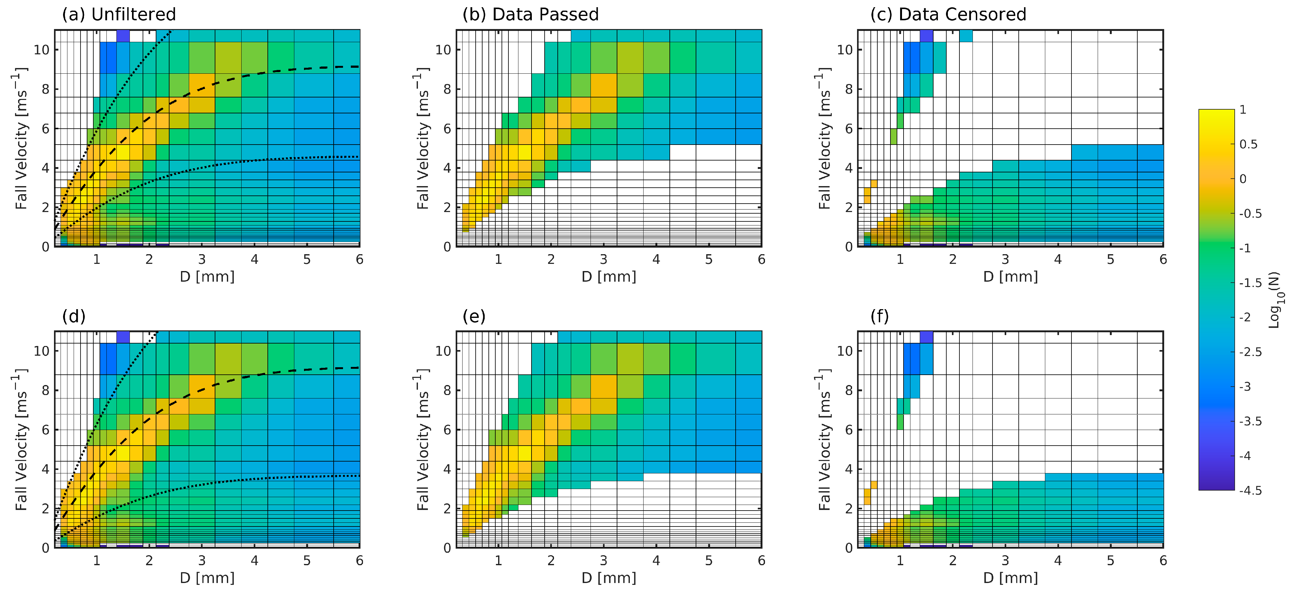
Use of an envelope of permitted vf as a function of D to exclude hydrometeors that are falling at velocities that may indicate signal contamination by splash or non-precipitation objects, has a crucial influence on the resulting DSD and RR, as illustrated by Equations (1) and (7). There, we follow DoE ARM quality control procedures [39]. Hydrometeor counts from this instrument are excluded from the analysis if they are reported in a vf class that falls outside of a ±50% envelope from the empirical observations of vt as a function of D presented by Gunn and Kinzer [42], (referred to herein as G and K +/− 50%; see Figure 2a). It is worthy of note that use of this ±50% envelope equates to a range of approximately 4.5 to 13.6 ms−1 for D = 5 mm, and thus includes modeled vt estimates for standard atmospheric conditions for solid spherical droplets and oblate spheres [56]. However, vt from Gunn and Kinzer [42] asymptotes to a constant value at smaller D than is indicated by some models [56]. Use of this data screening leads to removal of 28.9% of recorded hydrometeors (Figure 3a–c). Using a threshold of permitted vf of within +/− 60% of vt excludes 23.9% (Figure 3d–f) of recorded hydrometeors, similar to the 25% reported by Jaffrain and Berne [40]. Rejected hydrometeors are concentrated at D < 1 mm and exhibit vf < vt (i.e., many have vf ~1 ms−1). Possible causes of the large number of rejected hydrometeors when using the DoE ARM standard analysis procedure include the very high wind speed regimes at the DoE ARM site which causes the falling hydrometeors to exhibit non-negligible translational speeds [36,57]. Snow is relatively rare in the SGP. Snowflakes will tend to fall at considerably slower rates than droplets, and may be excluded by this data screening, but will tend to have little consequence for LEE due to their low mass and vf.
To compute the effective diameter of each hydrometeor for use in determining the kinetic energy transfer, we follow the procedure used within the OTT Parsivel2 software that is used to derive RR from the DSD [9]. Hence, AR is set as 1 for D < 1 mm, varies linearly from 1 to 0.7 for D = 1 to 5 mm, and is fixed at 0.7 for D > 5 mm (Figure 2b).
The impact disdrometer operated at the Lamont site since February 2006 is a Joss-Waldvogel type [26,58,59,60] manufactured by Distromet Ltd. Impact disdrometers inherently assume that the hydrometeors are falling at vt, so that their terminal fall velocities are used to derive the number concentrations by diameter. This type of disdrometer has been reported to measure droplets with D = 0.3 to 5.5 mm with a ±5% accuracy [26]. Background noise can induce measurement error, and there is the potential for under-sampling during very high RR, due to the ‘dead time’ of the instrument due to ringing in the cone after each impact. A channel correction is applied that scales with reported impacts at other D [60].
Here we assume vf for hydrometeors recorded by the impact disdrometer to be equal to the Gunn and Kinzer estimates for each of the 20 diameter classes (extending to 5.4 mm) reported by the impact disdrometer. Following DoE ARM data processing procedures [61], the diameters at which data are reported are assumed to represent the effective spherical diameter, and thus AR = 1.
Two-dimensional video disdrometers use two perpendicular high-speed cameras and two light sources to track hydrometeors as they fall through the viewing area, to record their shape, D and vf. The video disdrometer was manufactured by Joanneum Research Digital [48] and deployed at the Lamont site in February 2011 [62]. This 2D video instrument records droplet size distributions in 50 evenly sized diameter classes up to 9.9 mm [63]. It can directly detect vf for each hydrometer by the difference in detection time from the two vertically offset (~6–7 mm) cameras [23]. However, for processing speed in the following, vf is specified by D by the G and K curve, following the same approximation as used for the impact disdrometer. Some previous research has suggested that hydrometeors with D < 0.2 mm are subject to relatively large measurement uncertainty in video disdrometers [25], and that measurement uncertainty increases with increasing wind speed. However, in general, the video disdrometer is seen as a reference disdrometer and exhibits good closure in terms of RR and accumulated precipitation relative to tipping-bucket and weighing rain gauges [23]. Uniquely among the disdrometers considered here, this instrument can detect and report not only D, but also AR. Analyses of four years of individual hydrometeor AR from the video disdrometer indicate reasonable agreement with both assumptions made in the optical disdrometer and the approximation shown in Equation (5), in terms of the dependence on D. However, the data from the video disdrometer and Equation (5) suggest larger droplets are substantially more oblate than is currently being assumed in the optical disdrometer software (Figure 2b). In following analyses of the video disdrometer output, based on analysis of 4 years of 1 min individual hydrometeor observations (Figure 2b), the axis ratio is assumed to have the following dependence on the hydrometeor horizontal diameter, DHoriz:
A R = 0.0817 D H o r i z + 0.987 ,   f o r   D H o r i z < 10   m m 0.17 ,                 f o r   D H o r i z   10   m m
Earlier work [43] using an artificial rain shaft under very low wind conditions found the following mean axis ratios from a 2D video disdrometer: 0.98 (DHoriz = 1–1.5 mm), 0.911 (DHoriz = 2–2.5 mm), 0.844 (DHoriz = 3–3.5 mm), 0.771 (DHoriz = 4–4.5 mm), 0.704 (DHoriz = 5–5.5 mm), 0.645 (DHoriz = 6–6.5 mm), 0.589 (DHoriz = 7–7.5 mm), 0.520 (DHoriz = 8–8.5 mm), and 0.446 (DHoriz = 9–9.5 mm). For DHoriz > 4 mm, those values are substantially higher than the linear fit estimates presented in Figure 2b, but are also substantially lower than the assumptions made the in OTT Parsivel2 software. The precise source of the discrepancy between earlier studies and work presented here is currently not known, but may reflect differences in wind regimes. The relatively infrequent occurrence of hydrometeors with D > 4 mm means it is likely a small, but non-negligible, source of uncertainty in the current analyses.

2.3. Lidar Wind Speeds and Wind Turbine Power and RPM Curve

The 15 min mean wind speeds at 90 m a.g.l. from a Doppler lidar are used herein to represent hub-height winds (U) [64] (Figure 4a). They are used with the WindPACT 3.0 MW turbine power and RPM curves (Figure 4a) [52] to generate 1 min values of wind turbine tip speed and power production for use in the damage and LCoE modeling. This wind turbine was selected as typical of those deployed in 2021 in the U.S. onshore market, when the mean rated capacity of newly installed wind turbines in the U.S. grew to 3.0 MW [65].
The precis of 1 min rainfall rates (Figure 4b) and joint occurrence of rainfall rate and wind speed (Figure 4c) based on data from the DoE ARM site emphasizes that a typical wind turbine deployed in this region would frequently be at or near the rated rotor speed (i.e., hub-height winds (U) > 11 ms−1; Figure 4a) when precipitation is occurring. It further re-emphasizes that, although precipitation is relatively infrequent in the SGP [9], high-intensity precipitation (RR > 2.5 mmh−1) is frequently observed, including during periods when the wind turbine blades are rotating rapidly (Figure 4c).

2.4. Kinetic Energy of Impacts

A simple geometric model is used to estimate the kinetic energy of hydrometeor—blade impacts based on the hydrometeor mass, fall velocity, and blade velocity (and thus, swept volume per square meter of leading-edge area) in each 1 min period. Closing velocity, v c as a function of diameter (D) and fall velocity (vf) is calculated from hub-height wind speed, U, blade tip speed,   v b l a d e (calculated from U via the RPM curve, Figure 4a), and blade position,   ϕ t at time, t. The blade tip speed represents speeds in the blade area with the greatest potential for erosion [13]. The following method is derived from an analysis of the WT blade-hydrometeor closing velocities from [66]:
v c D , v f , t = U 2 + v b l a d e + v f · cos ϕ t 2 1 / 2
The impact rate (I, in impacts m−2) on the blade leading edge is calculated from the number density of the hydrometeors of a given diameter and closing velocity (N(D, vc)), and the closing velocity itself:
I D ,   v c , t = N D , v c · v c D ,   v f , t
This impact rate assumes that no hydrometeors are deflected out of the swept volume of the blade. Previous work has shown that only droplets with D < 0.2 mm have low enough inertia to be deflected from the blade by streamline deformation [67]. The KE of hydrometeor impacts is given by:
K E D , v c , t = 1 2 m D · v c D , v f , t 2
where m(D) is the mass of the hydrometeors as a function of effective diameter, computed from the measured horizontal diameter, taking into account an appropriate axis ratio (AR = 1 for the impact disdrometer, between 1 and 0.7 for the optical disdrometer, and 0.9 and 0.2 for the video disdrometer (Figure 2b)). Kinetic energy is then integrated over the 1 min period, assuming that all blade positions, ϕ, are equally likely, to derive the total kinetic energy for each minute of precipitation integrated over all diameter classes, and summed over all time intervals (t) to compute the total accumulated kinetic energy of impact. For legibility, in the following we use KE to refer to the total accumulated KE of impact (KEtot):
K E t o t = t D V c I D ,   v c , t K E D , v c , t

2.5. Modeling the Blade Lifetimes

A range of modeling techniques has been advanced to simulate the process of material stresses that lead to blade leading-edge erosion [67,68,69]. Herein, we use the Springer model [49,54] combined with Miner’s rule. The Springer model uses material properties of the blade and coating and the hydrometeor impact number, diameter, velocity and impact angle to estimate a distance to failure for each hydrometeor diameter. This distance to failure is the end of the incubation period for coating wear. Miner’s rule is used to integrate across all hydrometeor diameters, to quantify the accumulated distance to failure (ADF) [17,53].
A brief description of the implementation of the Springer model for coated WT blades is given below, and more details can be found in previous publications [17,53]. The number of impacts to failure per unit area, Ni, for a given droplet diameter D and impact velocity v (which is assumed to be the closing velocity) is given by:
N i = 4 π D 2 a 1 S e c σ 0 a 2
where S e c (Equation (19)) is the erosion strength of the blade coating and σ 0 is the average stress of the coating surface, given by:
σ 0 = v Z L cos θ ψ s c + 1 Z L Z c + 1 1 ψ s c ψ L c 1 1 e γ ( ψ L c + 1 ) ψ s c γ ψ s c + 1
where Z ( Z = ρ C ) is the impedance of each material (subscripts: L for liquid, c for coating, s for substrate), C is the elastic wave speed, ρ is the material density and ψ is the relative acoustic impedance (subscripts s c for substrate-coating, and L c liquid-coating (Equations (16) and (17)), and γ is the coating thickness parameter, representing the maximum number of reflections during the impact time within the coating thickness (Equation (18)):
ψ s c = Z s Z c Z s + Z c
ψ L c = Z L Z c Z L + Z c
γ = 2 C c Z c Z L + Z S D C l Z c + Z L Z c + Z S
S e c 4 b c 1 σ U c 1 2 ν c 1 σ I c σ U c b c 1 2 k ψ s c + 1
where σ u c is the ultimate tensile strength of the coating, b c is the coating Springer fatigue knee (calculated from the material fatigue knee, b 2 c , in Equation (20)), ν c is the coating Poisson ratio, and k is an average number of impacts based on γ (Equation (21)):
b c = b 2 c l o g 10 σ U c σ I c
k = 1 e γ 1 ψ s c ψ L c
A range of parameter values have been proposed for use in the Springer model [53]. Because the focus of this research is not, per se, to derive accurate blade lifetime estimates, but to illustrate differences that arise due to disdrometer metrology, here we use relatively conservative values drawn from two previous studies [17,53] (Table 1).

2.6. Modeling the Impact of Erosion-Safe Mode on LCoE

Estimates of the influence on the LCoE of implementation of wind turbine curtailment during highly erosive events are derived using:
L C o E = n = 1 i C A P E X n + O & M n / 1 + r n n = 1 i A E P / 1 + r n
along with the following assumptions:
  • Capital expenditures (CAPEX) for a 3 MW wind turbine = USD 4,386,000 and occur only in year 1 (n = 1). This value is based on capital expenditure of 1462 per kW for a land-based reference project using 2.8 MW wind turbines, used in the recent analysis of 2020 review of the costs of wind energy [70]. It is at the higher end of global mean values in 2020, which ranged from 1050 to 1450 USD/kW [71].
  • Fixed annual Operations and Maintenance (O&M) costs for a 3 MW wind turbine = USD 129,000. This value is based on O&M costs of 43 USD/kW/yr for a land-based reference project using 2.8 MW wind turbines, used in the recent analysis of the 2020 review of the costs of wind energy [70]. It assumed that these O&M costs do not include those associated with blade failure and replacement. The rate of 43 USD/KW/yr is at the mid-point of estimates (33–59 USD/kW/yr) for recently commissioned projects in a survey of US industry professionals performed in 2018–2019 [72].
  • Annual discount rate (r) = 0.0523. This rate is used as a reference rate in the 2020 review of the costs of wind energy [70].
  • The wind turbine lifetime is 25 years (i.e., i = 25). This project lifetime is used as a reference in the 2020 review of the costs of wind energy [70], and is consistent with expected lifetimes for many projects operating in the US. It is longer than the estimate of 20 years used in an analysis of lifetime extension of onshore wind turbines in Europe [73], but shorter than the 29.6 years derived from a recent survey of US wind industry professionals [74].
Once the accumulated distance to failure (summed over all hydrometeor diameters) has been reached in the Springer model calculations, we assume:
  • The damage is sufficient to merit total blade replacement, and the additional O&M expenditures for replacement of a blade = USD 200,000 [75] occur in that year.
  • Replacement of blades leads to 7 days of lost annual energy production (AEP). This is based on the information that most repairs take 1–3 days [75] and crews and specialist equipment may not be immediately available and/or prevailing meteorological conditions may limit turbine access. The reduction of AEP in the year when the replacement is modeled to occur is taken as 1/52 of total AEP.
In environments where relatively few events dominate the accumulated kinetic energy transfer to the blades and the increments in ADF, it may be desirable to enact erosion-safe mode and curtail production (and blade rotation) during those periods. Thus, we assess the degree to which curtailment of the wind turbine during such events in the US SGP can extend blade lifetime and what the influence is on LCoE of varying rates of curtailment. To evaluate the optimal duration of the operational safe mode needed to extend blade lifetimes and lead to minimization of the LCoE the following procedure is employed. For each time series from the three disdrometers, we incrementally remove 1 min or 10 min periods with the highest increment in ADF, and consider a range of zero curtailments to 0.5% of all 1 or 10 min periods, in increments of 0.01%. The use of the two integration time periods for these analyses is a recognition that although highly erosive periods are very short-lived, dynamic operation may more likely be implemented at a 10 min time scale.

3. Results

3.1. Rainfall Rates and Hydrometeor Size Distributions

Prior to using the time series of number counts in D, vf classes from each of the disdrometers to derive kinetic energy transfer and blade lifetime estimates, below we compare the derived DSD and inferred RR and interrogate possible causes of measurement differences.
Analyses of data from the optical disdrometer systematically lead to lower RR than those from either the impact or video disdrometer (Figure 5a,c). RR from the video disdrometer also tend to exceed those from the impact disdrometer (Figure 5b). The negative bias in estimated RR from the optical disdrometer relative to the video disdrometer is consistent with results from the DEVEX experiment in Iowa City [33], but the findings relative to a Joss-Waldvogel impact disdrometer are contrary to those from a study in Alabama [28]. Because of the critical importance of periods with high RR and wind speeds to kinetic energy transfer to wind turbine blades, in Figure 5 we conditionally sample the derived RR from each disdrometer by prevailing hub-height wind speed. Any dependence of the bias in RR on wind speed has important ramifications for uncertainty in the estimated impact of KE. While the offset between RR from the video and impact disdrometers is consistent across all wind speed classes (Figure 5b), the highest agreement for RR from the optical disdrometer relative to the other two is achieved at wind speeds associated with the highest rotor rotational speeds (i.e., U: 11–24 ms−1) (Figure 5a,c). Incorrect counting (possibly overestimation) of medium and large droplets (D > 2 mm) by Parsivel disdrometers during high wind speeds [34,35,36], may be partly compensated for by large D with erroneously low vf being filtered by the quality assurance algorithm.
Comparisons of mean hydrometeor size distributions conditionally sampled by rainfall rate (Figure 6) indicate three important features of the data: (i) Number concentrations for the smallest hydrometers (D < 1 mm) are substantially higher in data from the video disdrometer (cf. Figure 6a–c). These differences are especially pronounced at the highest RR. Undercounting by the impact disdrometer at high RR may be due to the ‘dead time’ in heavy rain, when smaller impacts are not logged, as two or more hydrometeors impact the disdrometer in a short interval. Alternatively, undercounting may be due to ambient noise (from the wind or generator) [26]. Undercounting of small hydrometeors by the optical disdrometer at high RR may be due to the assumption that only one hydrometeor is interrupting the beam at any time [23,28]. It may also be due to the vf data filter applied [40]. (ii) Hydrometeors with D ~ 4–5 mm are substantially more abundant in data from the optical disdrometer at all RR. Note the DSDs are limited by the maximum D observable with each disdrometer.

3.2. Impact Kinetic Energies

Although data from the three disdrometers are generally consistent in terms of detection of precipitation, the number of one-minute periods with non-zero KE is not identical among the three data sets (Table 2). The optical disdrometer reports ~ 22% fewer periods with RR (and hence KE) > 0 than the video disdrometer. However, the estimated annualized impact of KE, computed using data from the optical disdrometer with the data selection criterion applied meaning that vf must lie within ±50% of vt from Gunn and Kinzer [42], and using the AR assumptions described in Section 2.2, greatly exceeds estimates from the impact and video disdrometers. Indeed, it is a factor of 1.61 times that of the impact disdrometer, and a factor of 1.26 higher than estimates based on data from the video disdrometer (Table 2). Thus, consistent with the mean DSD shown in Figure 6, the greater prevalence of hydrometeors with D > 2 mm in the optical disdrometer data stream yields notably higher KE estimates. A further contributory factor to the higher KE computed based on data from the optical disdrometer is that among periods with nonzero precipitation logged by the optical disdrometer, 24.1% have wind speed at or above the rated speed (Figure 4a, i.e., U: 11 to 24.5 ms−1), compared with 17.1% for the impact disdrometer and 18.0% for the video disdrometer (Table 2). This implies that periods for which the optical disdrometer does not detect precipitation (and one or both of the other instruments do), tend to be those with lower U. These periods make only a small contribution to total KE, due to low rotor speeds.
When the envelope of permitted vf is expanded to include values within ±60% of vt from Gunn and Kinzer [42], the annualized total KE from impacts computed using data from the optical disdrometer increases by almost 15% (Table 2). Thus, the exact choice of vf filter has a substantial effect on the resulting DSD and KE of impact (Figure 3, Table 2). When no filter is applied to remove counts with very high or low vf, the annualized impact KE is much higher (7.31 × 10⁸ J m−2), due to the strong dependence of the derived number concentrations on counts with very low vf (see Equation (1)).
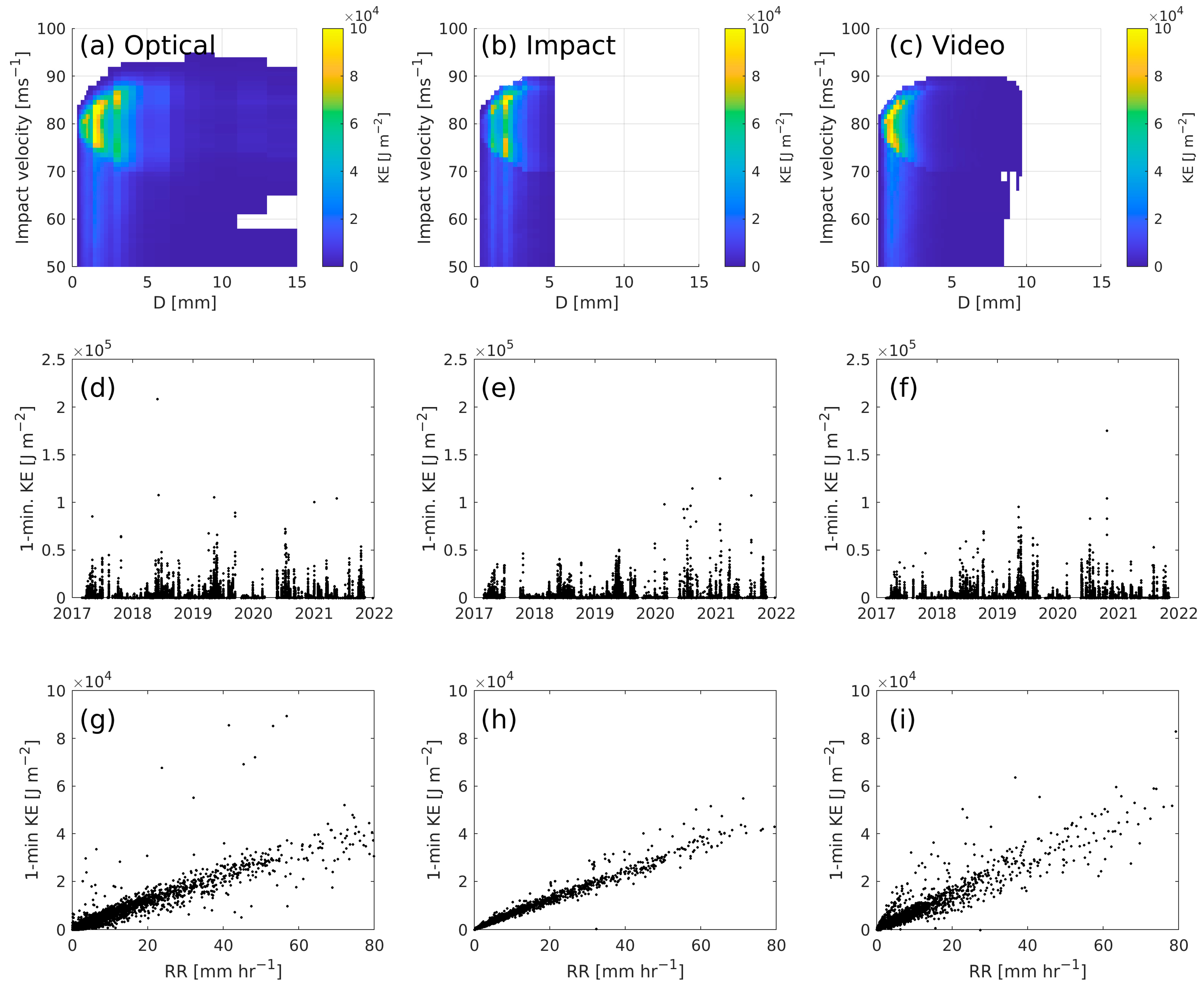
Impact KE is dominated by periods with closing (and hence impact) velocities near 80 ms−1 and D < 5 mm (Figure 7a–c). Thus, at this location, damaging events are concentrated at times when the blade is rotating at its maximum speed. However, as D (and vf) increase, the range of impact speeds contributing substantially to KE increases. This implies that hydrometers with D > 2 mm have sufficient vf (and mass) so that even when U < 11 ms−1, the kinetic energy of impact remains high. The largest hydrometeors reported by the optical and video disdrometers make only a relatively modest contribution to the KE of impact (Figure 7a–c). Thus, the differences between the disdrometers in terms of the range of observed D are likely to make only a fairly minor contribution to differences in KE. KE contributions from hydrometeors with 4 mm < D < 7 mm are notably higher for the optical disdrometer than for the video disdrometer, which also reports hydrometeors in this diameter range.
When the 1 min KE estimates and RR are conditionally sampled to include only periods when the blade would be rotating at the maximum speed (i.e., when U: 11.5–24 ms−1), analyses of data from all three disdrometers indicate a relatively consistent relationship between KE and RR, but also pronounced scatter (Figure 7g–i). This scatter illustrates the value in using high temporal resolution disdrometer DSD measurements to compute KE of impacts and resulting blade damage, rather than relying on a weighing or tipping-bucket rain gauge that reports only total accumulated precipitation.
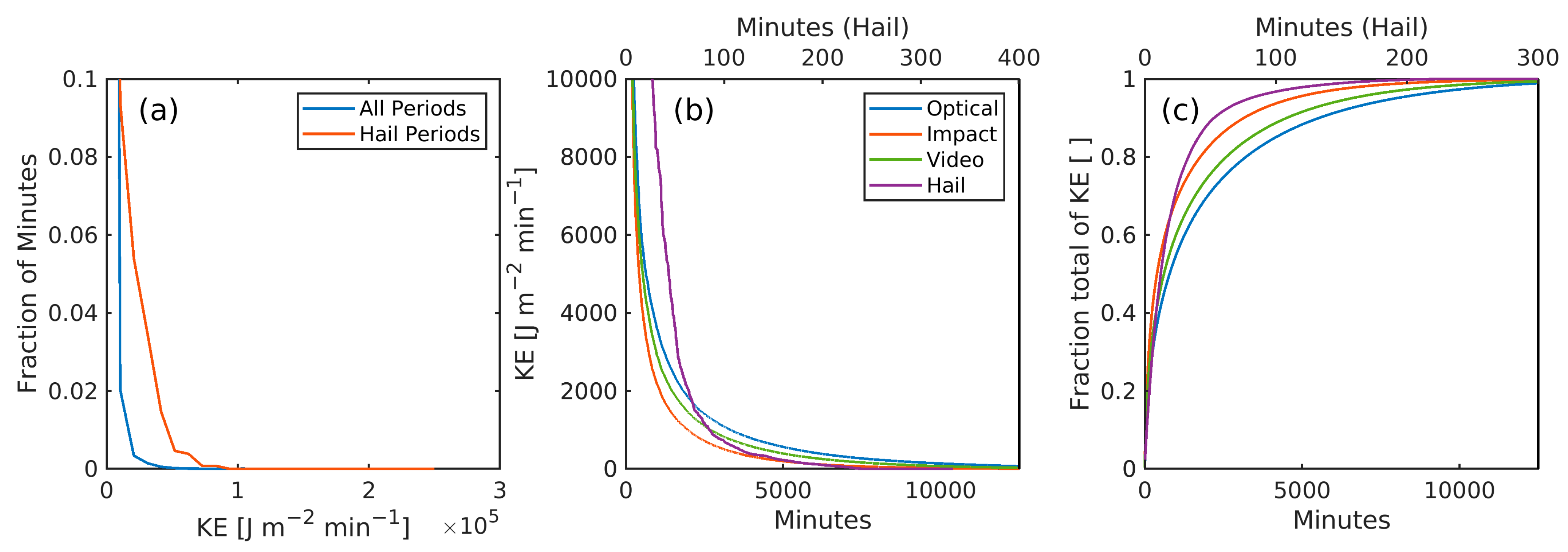
Data analyses based on all three disdrometers indicate that periods with high-impact KE are highly concentrated in time and are most likely in the warm season months (Figure 7d–f), when deep convection and both very heavy precipitation and hail are most frequent in the SGP [51]. The 1 min impact KE is <1000 J m−2 for all but the most intense 2000 to 4000 min (~50 h) per year (Figure 8a,b). Estimates based on impact disdrometer observations show the greatest concentration of KE in time, with 50% of KE concentrated in 387 min per year. Comparable estimates are 788 min, based on analyses of DSD from the optical disdrometer and 608 min for the video disdrometer (Figure 8c). The heavy-tailed nature of the probability distributions of KE provides a strong motivation for the later assessment of the erosion-safe mode operation.
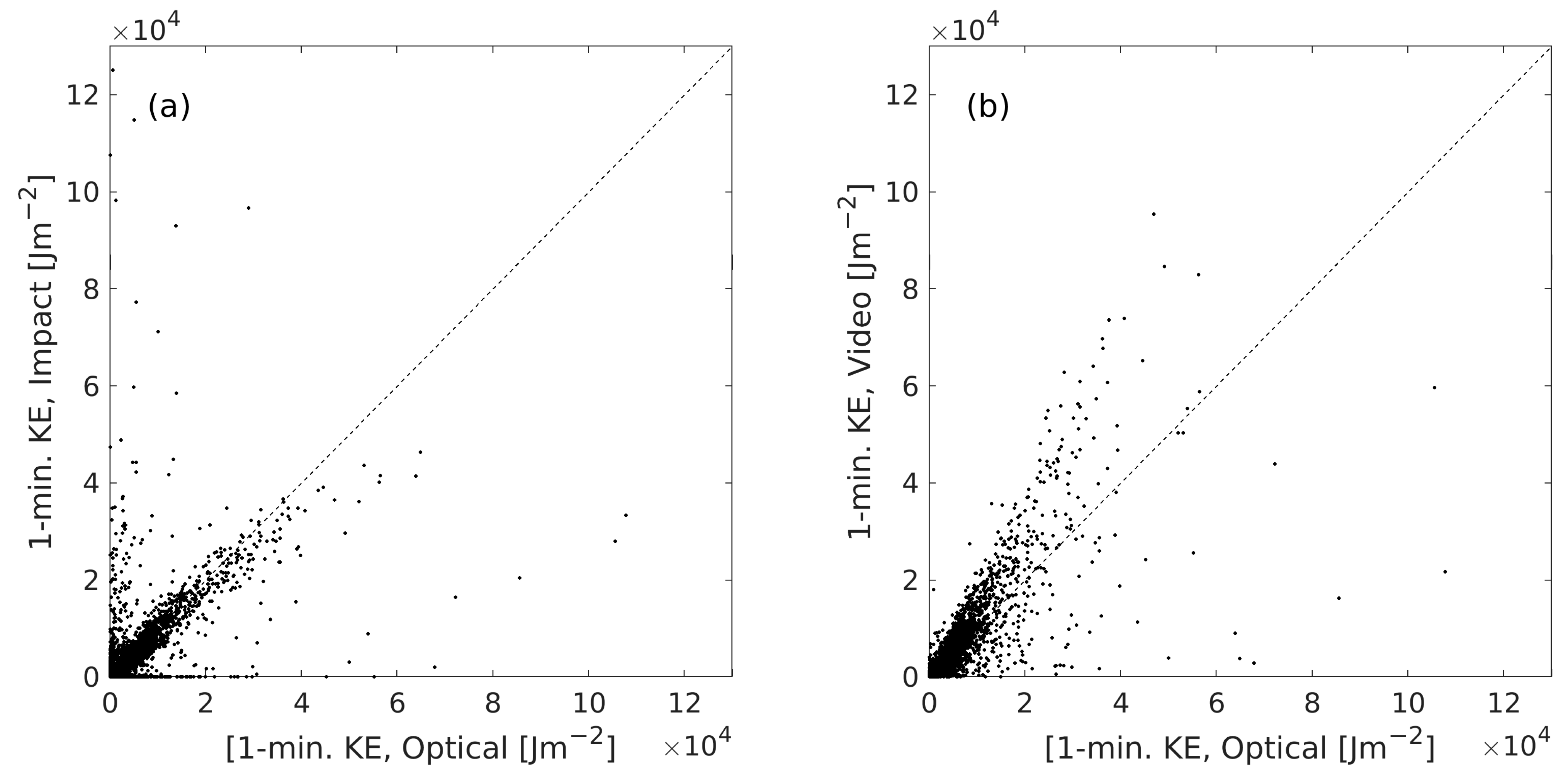
The KE of impact within individual 1 min periods also varies based on analyses of data from the three disdrometers (Figure 9). When comparing the 1 min KE from concurrent periods, there is often good agreement between the optical and impact disdrometers (with KE based on data from the optical disdrometer being somewhat higher). However, there are some periods where the KE estimate from one instrument is near to zero and the other is large (Figure 9a). For the highest KE of impacts, values estimated from the video disdrometer data tend to be higher than those from the optical disdrometer (Figure 9b). Pairwise comparison of one-minute KE values indicates that only 39% of values from the impact disdrometer are within ±20% of those from the optical disdrometer. KE values from the video disdrometer are within ±20% of those of the optical disdrometer in 41% of minutes. Conditionally sampling the data to include only minutes with KE from the optical disdrometer > 10,000 J m−2, the degree of agreement between the values from the impact and optical disdrometer increases, but not between KE estimates from the optical and video disdrometer. When KE from the optical disdrometer data > 10,000 J m−2, 59% of KE values from the impact disdrometer data lie within ±20% of those from the optical disdrometer, but only 25% of values from the video disdrometer time series do.
Past research has indicated that materials stresses induced by hail impacts on the blade may be amplified relative to rain droplets, due to the larger mass and diameter of hail and the relative hardness of the hydrometeor. Data from the optical disdrometer indicate hail periods are associated with more intense precipitation overall than non-hail periods. Hail is also associated with a higher number of concentrations of hydrometeors across all diameters and a much greater frequency of large hydrometeors (Figure 10b). Soft hail periods are associated with lower-intensity precipitation and small diameter hydrometeors (Figure 10c). While this is, naturally, in part a product of the proprietary algorithm used to assign the WC, it is also consistent with the meteorological literature [76]. Kinetic energy contributions from hail have a local maximum at D ~ 6 mm, whereas KE contributions for other periods are mostly restricted to D < 4 mm (Figure 10 d–f). While the peak KE of impact periods are associated with rain, many of the highest kinetic energy minutes are associated with the presence of hail (Figure 10 and Figure 11). KE values associated with hail events are even heavier tailed than those associated with rain. A total of 0.5% of minutes with hail are associated with KE of impact > 50,000 J m−2 (Figure 8) and 90% of the KE contribution from hail comes in < 50 min per year (Figure 8c).
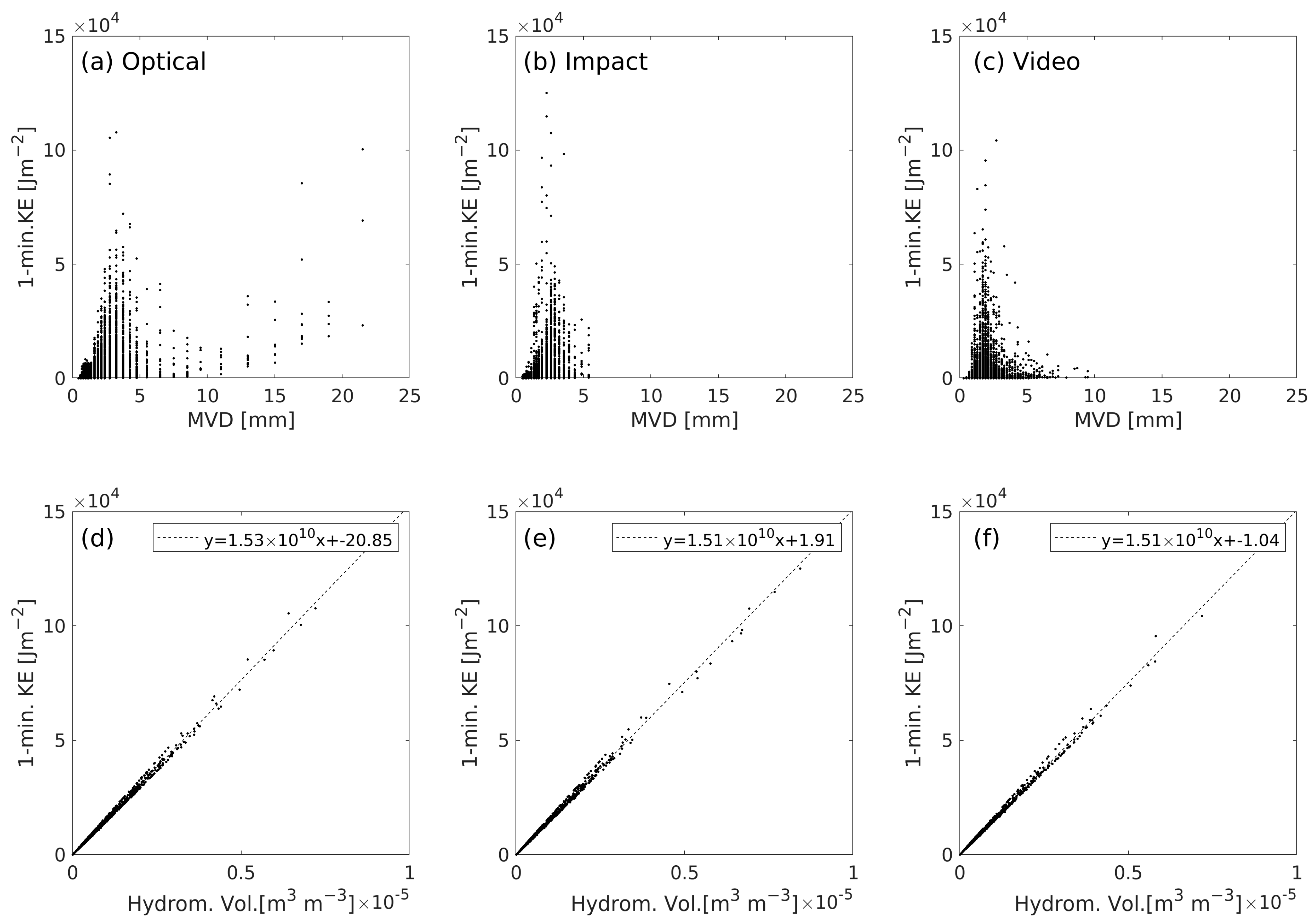
As described above, although the RR is correlated with KE of impacts, there is substantial minute-to-minute variability in the relationship, due to variations in the precise DSD. This is demonstrated below, using the variability in the median volume diameter (MVD) of the hydrometeors, which is the diameter that half of all hydrometers measured during that 1 min period exceed. MVDs from all three disdrometers are most frequently < 3 mm, with the periods of highest KE typically being associated with MVD near 2 or 3 mm (Figure 12a–c). Analysis of data from the optical disdrometer indicate some high KE periods associated with much larger MVD (10–22 mm), which correspond to periods with large hail. These diameters are not sampled by the other two disdrometers.
An a priori expectation can be advanced that, for a given blade rotational speed, the hydrometeor volume (volume fraction occupied by water) should be strongly associated with KE, since it is directly proportional to the mass of hydrometeors impacting the blade. KE totals can be explained by the blade tip speed, V h y d , hydrometeor density (m3/m3 of air), and the swept volume of the blade tip ( V S w e p t in m3min−1m−2):
V S w e p t = v b l a d e Δ t
The total mass of hydrometeors encountered by the blade in one minute (mimp in kg min−1) can be derived for a given hydrometeor density (ρ) using:
m i m p = V S w e p t · V h y d · ρ
and the total 1 min KE can be estimated by:
K E 1 2 m i m p v b l a d e 2 = 1 2 Δ t · V h y d · ρ · v b l a d e 3
For v b l a d e = 80   ms 1 ,   ρ = 1000   kgm 3 ,   Δ t = 60 s:
K E V h y d 1.54 × 10 10 J   m 2 min 1
This expectation of a strong correlation between Vhyd and the KE is observed in the analysis output (Figure 12d–f). Indeed, for U = 11.5–24 ms−1, the linear correlation coefficient between Vhyd and KE ≥ 0.999. The slope of the linear fits of KE and total hydrometeor volume range from 1.51 × 10¹⁰ to 1.53 × 10¹⁰ (with negligible y-intercepts), consistent with expectations from Equation (26).

3.3. Blade Lifetimes from the Springer Model

The Springer model is designed to represent the ADF (i.e., the end of the damage incubation period), and thus to provide an estimate of the coating lifetime. Using the conservative values for the model coefficients described in Table 1, analysis of data from the optical, impact and video disdrometers indicate the end of the incubation period at between 15 and 27 years (Table 2). Analysis of data from the optical disdrometer yields the shortest time to coating failure (15 years), while the estimate from the video disdrometer is almost 2 years longer, and that based on data from the impact disdrometer is over 11 years longer. The inference is that the type of disdrometer deployed to make a priori estimates of the potential for LEE would have a profound impact on estimates of lifetimes and the cost-effectiveness of deploying preventative measures, such as reinforcing the leading edge.
Even more pronounced is the impact of the data screening procedure to exclude hydrometeors with very low and very high vf. Screening of the data from the optical disdrometer to exclude signals that may not be associated with hydrometeors (i.e., use of vt-vf, filters) also has a profound influence on estimated blade lifetimes. Use of the DoE ARM best practice for quality assurance of the optical disdrometer data (i.e., that vf must lie within ±50% of vt) yields an estimated blade lifetime of 15.7 years (Table 2). Use of an expanded range of acceptable values, i.e., vf must lie within ±60% of vt, lowers the lifetime to 13.8 years, while inclusion of all droplets reported by the Parsivel2 optical disdrometer in the ADF from the Springer model yields a blade lifetime of 1.9 years.
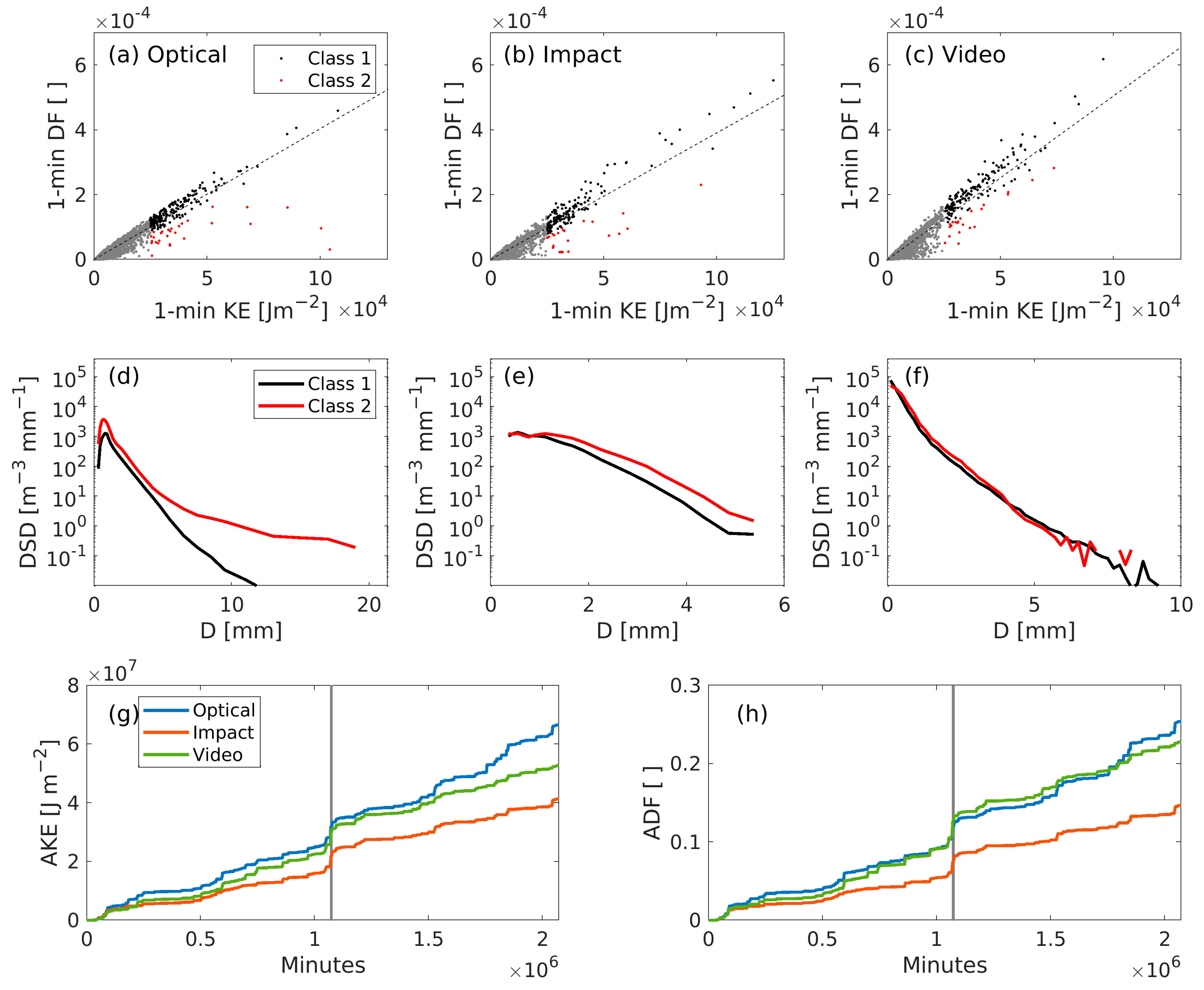
As expected, there is a strong and consistent relationship between 1 min estimates of impact KE and accumulated distance to failure (aggregated across all hydrometeor diameters). Based on analyses presented herein, on average, a 1 J m−2 increment in KE corresponds to a 3.8 × 10⁻⁹ to 5.0 × 10⁻⁹ increment in distance to failure integrated over all diameters (DF; Figure 13a–c and Table 3, mean ratios and slopes). However, individual 1 min periods deviate markedly from this expectation, due to variations in the precise DSD and vf. Examining only periods when the KE > 2.5 × 10⁵ J m−2 and dividing DF values into those where DF < 80% of the expectation and all other DF values, indicates that periods when ADF is below expectations are typically associated with a greater proportion of large-diameter hydrometers (Figure 13d–f).
Accumulated distance to failure (ADF) and accumulated kinetic energy (AKE) exhibit similar time histories (Figure 13g,h). Both also illustrate the extremely episodic nature of highly erosive events. Based on analysis of data from the optical disdrometer, a single six-day period (20–25 May 2019) contributed 6.74% of the 4-year ADF and 6.31% of AKE. This period was characterized by two major convective outbreaks, each of which contained multiple 1 min periods with RR > 100 mmh−1 and a high prevalence of U between 11.5 and 24 ms−1, when the blade rotational speed is maximized. The presence of such periods within the data record emphasizes both the importance of long records in characterizing the hydroclimate and the erosion potential of a given location and the potential benefit of erosion-safe mode operation. The time series of ADF and AKE show analyses of data from the impact disdrometer result in systematically lower damage estimates than for the other two disdrometers. Estimates of ADF and AKE from the video disdrometer are also generally lower than those from the optical disdrometer. However, individual events (including one during the 20–25 May 2019 period) made a substantially higher contribution to ADF from the video disdrometer than is evident in analyses based on the optical disdrometer (Figure 13h). Accordingly, the relative ranking of ADF from these two instruments varies through time (Figure 13h).

3.4. LCoE and Erosion-Safe Mode

The estimated AEP for the 3 MW wind turbine based on hub-height wind speeds from the Doppler lidar is approximately 10.88 GWh/yr. This equates to a mean capacity factor of 41.4% (Figure 14 and Figure 15). This is equal to the average net capacity factor in 2020 for US projects built from 2014 to 2019 [65]. The LCoE for the base-case without implementing erosion-safe mode (i.e., curtailment during highly erosive periods) derived using the cost assumptions given above is 28–30.5 USD/MWh. This is at the lower end of the current national average LCoE (computed excluding production-tax credit) of approximately 32 USD/MWh [77,78], likely due in part to the exceptionally favorable wind conditions in the Southern Great Plains. Estimated mean LCoE operating for wind plants in the ERCOT grid operator region (most of Texas) is 29 USD/MWh [78].
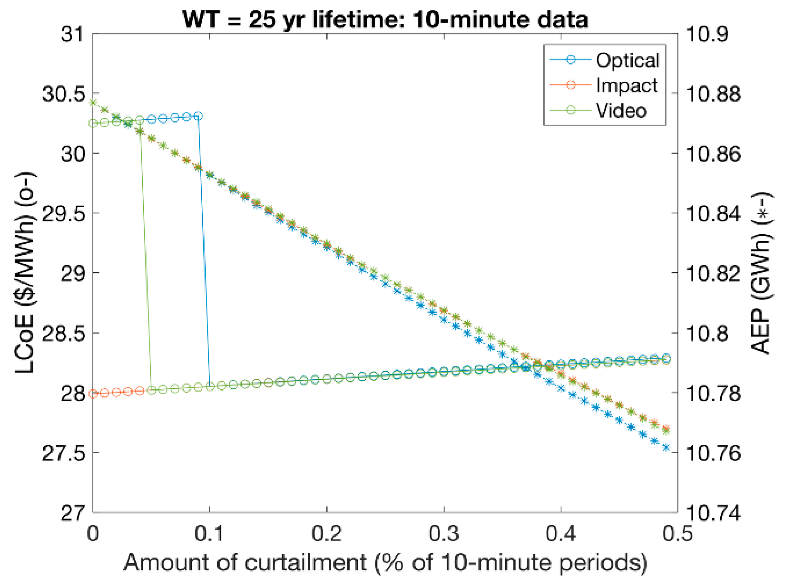
Using the Springer model for lifetime assessment, based on the hydrometeor size distributions from the three disdrometers, an analysis was undertaken by removing periods with highest increment in ADF and then recalculating the ADF and the coating lifetime. The LCoE is then also recomputed for that new lifetime (i.e., delayed O&M costs for blade replacement and associated loss of production) and with the reduced AEP due to the curtailment. This analysis is performed using two different time intervals: 10 min and 1 min. In the former, the 1 min estimates of ADF and AE from each 1 min period are averaged within 10 min blocks, prior to selection of the 0.0X% most damaging periods.
Analyses based on hydrometeor DSD from the impact disdrometer indicate a blade lifetime from the Springer model of >25 years (Table 2). Thus, there is no benefit from erosion-safe mode operation can be achieved, since the wind farm lifetime assumed in these analyses is 25 years. However, hydrometeor DSD from both the video and optical disdrometer in the Springer model indicate blade coating lifetimes <25 years (Table 2). Data from the video disdrometer indicate that a curtailment of 26 10 min periods (or 4.3 h) yields the lowest LCoE. Hydrometeor DSD from the optical disdrometer indicate that curtailment during 52 10 min periods per year (or 8.7 h) yields the lowest LCoE (Figure 14).
As shown above (Figure 8), extremely damaging hydroclimatic events are very short-lived and typically do not extend over a 10 min period. Assuming down-regulation could be implemented on shorter time scales of 1 min for only ~160 min per year (<3 h) needs to be subject to curtailment to minimize LCoE, based on analyses using data from the video disdrometer (Figure 15). Equivalent analyses based on data from the optical disdrometer indicate minimum LCoE for curtailment during an average of ~415 min per year (7 h).
It is worthy of note that the highly damaging periods (i.e., periods with high incremental ADF) tend to be associated with high wind speeds and thus considerable power production (i.e., wind turbines operating at, or very near to, rated power). A 0.1% curtailment corresponds to a ~0.2% reduction in AEP, since the most erosive events are primarily at times of above-rated wind speed. Nevertheless, this loss of production is compensated for by the increment in blade lifetimes for the costings described in Section 2.6.

4. Discussion

The research presented herein has a range of important implications for the wind energy industry. The following lists the key results as they relate to the explicit goals of this analysis:
  • Quantify and characterize differences in hydrometeor DSD due to disdrometer metrology and illustrate the influence of those differences and key data processing decisions on resulting hydrometeor size distributions and rainfall rates. Efforts to quantify relative damage potential across different locations are critically contingent on the metrology used to characterize the site hydroclimate. The degree to which the disdrometer technology used influences the kinetic energy of impacts and/or blade lifetimes from the Springer model is also likely to be partly a function of the prevailing hydroclimate. The precise choice of the filter used to exclude signals associated with anonymous fall velocities also has a notable effect on hydrometeor concentrations and RR. Using a filter for vf so that it must lie within ±50% of the terminal fall velocity estimated by Gunn and Kinzer [42] excludes 29% of droplets reported by the optical disdrometer. Using an envelope of ±60% of the terminal fall velocity estimated by Gunn and Kinzer [42] excludes 24%. The optical and impact disdrometers are also subject to missed counts, due to simultaneous hydrometeor interactions with the sensor, which has a detectable effect on DSDs at high RR, especially for small hydrometeor diameters. The closure between RR from the disdrometers also exhibits a consistent dependence on wind speeds, with the optical disdrometer appearing to exhibit greatest sensitivity to wind speed.
  • Estimate annual average kinetic energy transfer to blades from hydrometeor impacts and quantify uncertainty due to disdrometer metrology. The total estimated kinetic energy varies between 4.14 × 10⁷ J m−2 (using data from the impact disdrometer) and 6.66 × 10⁷ J m−2 (using data from the optical disdrometer), due to differences in the reported number counts and derived DSD. Although there is a positive relationship between 1 min kinetic energy of impact accumulated across all hydrometeor diameters and rainfall rates, there is considerable scatter. This reemphasizes the critical need for droplet size distribution, fall velocities and axis ratio measurements, in order to make robust damage estimates. Annualized KE of impacts based on data from the optical disdrometer are very sensitive to the precise data selection criterion applied based on vf. When the envelope of permitted vf is expanded to include values within ±60% of vt from Gunn and Kinzer [42], the annualized total KE is increased by almost 15%, and when no filter is applied the annualized total KE is increased by a factor of 10.
  • Estimate wind turbine blade lifetimes using the Springer model [49] and quantify uncertainty due to disdrometer metrology. Estimates of blade coating lifetime from the Springer model vary significantly among the three disdrometer data sets. From most erosive to least erosive, the coating lifetimes are 15.7 years (based on data from the optical disdrometer with a +/− 50% vf window), 17.5 years (video disdrometer) and 27.2 years (impact disdrometer). These disparate results would lead a wind plant owner/operator to choose very different LEE mitigation strategies. This reinforces the urgent need for research to better characterize disdrometer performance for this application. In the current work, hailstone impacts are modelled as being equivalent to raindrop impacts. Appropriate modeling of solid-phase hydrometeor impacts is a matter of great importance that is being addressed by laboratory testing [79,80].
  • Evaluate the degree to which highly erosive events are concentrated in time and attributable to the occurrence of hail. The wind and hydroclimate of the US Southern Great Plains is such that damaging events are highly concentrated in time. Up to half of annualized KE of impact is associated with 6–12 h in the year. In the 5-year period from which data are collated to build a representative data set of 4-year equivalent duration, a single 6-day period contributed 6.74% of the 4-year accumulated distance to failure and 6.31% of the accumulated kinetic energy transfer. Even excluding any influence from hydrometeor hardness, hail, which occurs in fewer than 1/80th of precipitation periods, contributes nearly 10% of annualized KE transfer to the blades, due to the large associated hydrometeor diameters.
  • Evaluate cost effectiveness of erosion-safe mode, and the influence of disdrometer metrology on optical erosion-safe mode curtailment strategy. This research suggests that adopting erosion-safe mode, wherein the wind turbine is curtailed during the most erosive events, could yield substantial LCoE benefits. However, the cost-effectiveness of this strategy and the optimal amount of curtailment is a strong function of the disdrometer from which the hydrometeor data are drawn. Optimal curtailment is almost half as long when DSD from the video disdrometer are used in the Springer model, relative to those from the optical disdrometer. Lifetimes estimated using data from the video disdrometer indicate that the lowest LCoE, associated with a curtailment of 26 10 min periods (or 4.3 h), yields the lowest LCoE. Using hydrometeor DSD from the optical disdrometer indicates that curtailment during 52 10 min periods per year (or 8.7 h) yields the lowest LCoE. Assuming curtailment could be operationalized on a 1 min timescale, only ~160 min per year (<3 h) need be subject to curtailment to minimize LCoE, based on analyses using data from the video disdrometer.
There are a number of important caveats to the work presented herein. First, the KE of impact and the coating lifetimes computed using the Springer model may well be underestimated and overestimated, respectively, due to the very strict data control procedure applied to exclude hydrometeors falling at velocities that differ appreciably from expected terminal fall velocities. Second, a critical uncertainty in terms of actual LEE potential/lifetimes is that our modeling with Springer and for the KE transfer implicitly assumes that the material response to hailstones is equal to that of rain droplets of equivalent diameter. This is not accurate [13], and is likely to lead to negative bias in the hail contribution to damage.
The results presented here with regards to the importance of disdrometer metrology to damage estimation are likely relatively robust with respect to the precise data screening procedure applied. Nevertheless, the precise threshold that should be used to screen disdrometer data to exclude signal contamination from splash/non-hydrometeor objects from consideration demands further research. Indeed, analyses presented herein indicate the urgent need for best practice to be developed for data quality control of disdrometer data in the context of wind turbine blade leading-edge erosion. There is also a need to perform further instrument closure experiments to better understand the relative performance of different disdrometers under the atmospheric conditions of greatest importance to the wind energy industry.

5. Conclusions

Accurate estimation of LEE potential is of critical importance for both wind farm planning and operation. In the wind farm planning phase, availability of a priori estimates of the probability of atmospheric conditions associated with large materials stresses could guide decisions regarding whether to apply additional leading-edge protection prior to wind turbine deployment. In wind farm operation, the availability of short-term forecasts or nowcasts from models of measurements of highly erosive events could inform decisions regarding whether to curtail the wind turbines or slow blade rotation, in order to reduce the kinetic energy of impacts. However, large uncertainties associated with the detection and quantification of hydrometeor number, type, and phase preclude accurate characterization of the likely LEE at the event and/or climate time scales.
Based on co-located disdrometer observations in the US SGP, the choice of disdrometer and data post-processing procedures can make a ~60% difference in estimates of the kinetic energy of impact and the resulting blade lifetimes. In this location, up to 50% of the material stresses responsible for LEE may occur during just 6–12 h per year. The implication is that proper assessment of relative LEE potential across sites may require long measurement campaigns, and also that measurement (and modeling) fidelity is particularly required for these short-lived periods when high wind speeds co-occur with very heavy precipitation and the occurrence of hail. This time concentration of potentially damaging events also has implications for erosion mitigation. Operating a wind turbine in erosion-safe mode (curtailing rotor speed to zero) during the most erosive 0.1–0.2% of 10 min periods leads to a minimum estimated LCoE. However, the amount of curtailment required is also strongly influenced by the disdrometer type used to measure the hydrometeor size distribution and fall velocity.

Author Contributions

Conceptualization, S.C.P.; methodology, S.C.P. and F.L.; software, S.C.P. and F.L.; validation, F.L.; formal analysis, S.C.P. and F.L.; investigation, S.C.P. and F.L.; resources, S.C.P.; data curation, F.L.; writing—original draft preparation, S.C.P. and F.L.; writing—review and editing, S.C.P. and F.L.; visualization, S.C.P.; supervision, S.C.P.; project administration, S.C.P.; funding acquisition, S.C.P. All authors have read and agreed to the published version of the manuscript.

Funding

This work is funded by the U.S. Department of Energy via a sub-contract to Sandia National Laboratory and grant (DE-SC0016605), plus NASA grant #80NSSC21K1489. Computational resources to S.C.P. used in these analyses are provided by the NSF Extreme Science and Engineering Discovery Environment (XSEDE and XSEDE2) (award TG-ATM170024).

Data Availability Statement

Data from the DoE ARM site are available from: https://www.arm.gov/data/ (accessed on 7 February 2023).

Acknowledgments

The authors would like to acknowledge the scientists, engineers and technicians of the DoE ARM program for producing the high-quality observations that made this work possible.

Conflicts of Interest

The authors declare no conflict of interest.

References

  1. Mishnaevsky, L., Jr.; Hasager, C.B.; Bak, C.; Tilg, A.-M.; Bech, J.I.; Rad, S.D.; Fæster, S. Leading edge erosion of wind turbine blades: Understanding, prevention and protection. Renew. Energy 2021, 169, 953–969. [Google Scholar] [CrossRef]
  2. Sareen, A.; Sapre, C.A.; Selig, M.S. Effects of leading edge erosion on wind turbine blade performance. Wind Energy 2014, 17, 1531–1542. [Google Scholar] [CrossRef]
  3. Gaudern, N. A practical study of the aerodynamic impact of wind turbine blade leading edge erosion. J. Phys. Conf. Ser. 2014, 524, 012031. [Google Scholar] [CrossRef]
  4. Froese, M. Wind-farm owners can now detect leading-edge erosion from data alone. Wind Eng. Dev. 2018. Available online: https://www.windpowerengineering.com/wind-farm-owners-can-now-detect-leading-edge-erosion-from-data-alone/ (accessed on 1 October 2022).
  5. Maniaci, D.C.; MacDonald, H.; Paquette, J.; Clarke, R. Leading Edge Erosion Classification System; Technical Report from IEA Wind Task 46 Erosion of Wind Turbine Blades; IEA: Paris, France, 2022; p. 52. Available online: https://iea-wind.org/task46/t46-results/ (accessed on 1 October 2022).
  6. Bech, J.I.; Hasager, C.B.; Bak, C. Extending the life of wind turbine blade leading edges by reducing the tip speed during extreme precipitation events. Wind Energy Sci. 2018, 3, 729–748. [Google Scholar] [CrossRef]
  7. Bartolomé, L.; Teuwen, J. Prospective challenges in the experimentation of the rain erosion on the leading edge of wind turbine blades. Wind Energy 2019, 22, 140–151. [Google Scholar] [CrossRef]
  8. Zhang, S.; Dam-Johansen, K.; Nørkjær, S.; Bernad, P.L., Jr.; Kiil, S. Erosion of wind turbine blade coatings–design and analysis of jet-based laboratory equipment for performance evaluation. Prog. Org. Coat. 2015, 78, 103–115. [Google Scholar] [CrossRef]
  9. Pryor, S.C.; Barthelmie, R.J.; Cadence, J.; Dellwik, E.; Hasager, C.B.; Kral, S.T.; Reuder, J.; Rodgers, M.; Veraart, M. Atmospheric Drivers of Wind Turbine Blade Leading Edge Erosion: Review and Recommendations for Future Research. Energies 2022, 15, 8553. [Google Scholar] [CrossRef]
  10. Letson, F.; Barthelmie, R.J.; Pryor, S.C. RADAR-derived precipitation climatology for wind turbine blade leading edge erosion. Wind Energy Sci. 2020, 5, 331–347. [Google Scholar] [CrossRef]
  11. Macdonald, J.; Stack, M. Some thoughts on modelling hail impact on surfaces. J. Bio-Tribo-Corros. 2021, 7, 37. [Google Scholar] [CrossRef]
  12. Kim, H.; Kedward, K.T. Modeling hail ice impacts and predicting impact damage initiation in composite structures. AIAA J. 2000, 38, 1278–1288. [Google Scholar] [CrossRef]
  13. Keegan, M.H.; Nash, D.; Stack, M. On erosion issues associated with the leading edge of wind turbine blades. J. Phys. D Appl. Phys. 2013, 46, 383001. [Google Scholar] [CrossRef]
  14. Savana, R. Effect of Hail Impact on Leading Edge Polyurethane Composites. Ph.D. Thesis, Delft University of Technology, Delft, The Netherlands, 2022. Available online: http://repository.tudelft.nl/ (accessed on 20 October 2022).
  15. Frost-Jensen Johansen, N.; Mishnaevsky, L., Jr.; Dashtkar, A.; Williams, N.A.; Fæster, S.; Silvello, A.; Cano, I.G.; Hadavinia, H. Nanoengineered graphene-reinforced coating for leading edge protection of wind turbine blades. Coatings 2021, 11, 1104. [Google Scholar] [CrossRef]
  16. Kyle, R.; Wang, F.; Forbes, B. The effect of a leading edge erosion shield on the aerodynamic performance of a wind turbine blade. Wind Energy 2020, 23, 953–966. [Google Scholar] [CrossRef]
  17. Herring, R.; Domenech, L.; Renau, J.; Šakalytė, A.; Ward, C.; Dyer, K.; Sánchez, F. Assessment of a wind turbine blade erosion lifetime prediction model with industrial protection materials and testing methods. Coatings 2021, 11, 767. [Google Scholar] [CrossRef]
  18. Verma, A.S.; Noi, S.D.; Ren, Z.; Jiang, Z.; Teuwen, J.J. Minimum leading edge protection application length to combat rain-induced erosion of wind turbine blades. Energies 2021, 14, 1629. [Google Scholar] [CrossRef]
  19. Godfrey, M.; Siederer, O.; Zekonyte, J.; Barbaros, I.; Wood, R. The effect of temperature on the erosion of polyurethane coatings for wind turbine leading edge protection. Wear 2021, 476, 203720. [Google Scholar] [CrossRef]
  20. Major, D.; Palacios, J.; Maughmer, M.; Schmitz, S. Aerodynamics of leading-edge protection tapes for wind turbine blades. Wind Eng. 2021, 45, 1296–1316. [Google Scholar] [CrossRef]
  21. Hasager, C.B.; Vejen, F.; Skrzypiński, W.R.; Tilg, A.-M. Rain erosion load and its effect on leading-edge lifetime and potential of erosion-safe mode at wind turbines in the North Sea and Baltic Sea. Energies 2021, 14, 1959. [Google Scholar] [CrossRef]
  22. Skrzypiński, W.; Bech, J.; Hasager, C.B.; Tilg, A.; Bak, F.V.C. Optimization of the erosion-safe operation of the IEA Wind 15 MW Reference Wind Turbine. J. Phys. Conf. Ser. 2020, 1618, 052034. [Google Scholar] [CrossRef]
  23. Raupach, T.H.; Berne, A. Correction of raindrop size distributions measured by Parsivel disdrometers, using a two-dimensional video disdrometer as a reference. Atmos. Meas. Tech. 2015, 8, 343–365. [Google Scholar] [CrossRef]
  24. Thurai, M.; Gatlin, P.; Bringi, V.; Petersen, W.; Kennedy, P.; Notaroš, B.; Carey, L. Toward completing the raindrop size spectrum: Case studies involving 2D-video disdrometer, droplet spectrometer, and polarimetric radar measurements. J. Appl. Meteorol. Climatol. 2017, 56, 877–896. [Google Scholar] [CrossRef]
  25. Tokay, A.; Kruger, A.; Krajewski, W.F. Comparison of drop size distribution measurements by impact and optical disdrometers. J. Appl. Meteorol. Climatol. 2001, 40, 2083–2097. [Google Scholar] [CrossRef]
  26. Tokay, A.; Bashor, P.G.; Wolff, K.R. Error characteristics of rainfall measurements by collocated Joss–Waldvogel disdrometers. J. Atmos. Ocean. Technol. 2005, 22, 513–527. [Google Scholar] [CrossRef]
  27. Kathiravelu, G.; Lucke, T.; Nichols, P. Rain drop measurement techniques: A review. Water 2016, 8, 29. [Google Scholar] [CrossRef]
  28. Tokay, A.; Wolff, D.B.; Petersen, W.A. Evaluation of the new version of the laser-optical disdrometer, OTT Parsivel2. J. Atmos. Ocean. Technol. 2014, 31, 1276–1288. [Google Scholar] [CrossRef]
  29. Peters, G.; Fischer, B.; Münster, H.; Clemens, M.; Wagner, A. Profiles of raindrop size distributions as retrieved by microrain radars. J. Appl. Meteorol. 2005, 44, 1930–1949. [Google Scholar] [CrossRef]
  30. Johannsen, L.L.; Zambon, N.; Strauss, P.; Dostal, T.; Neumann, M.; Zumr, D.; Cochrane, T.A.; Blöschl, G.; Klik, A. Comparison of three types of laser optical disdrometers under natural rainfall conditions. Hydrol. Sci. J. 2020, 65, 524–535. [Google Scholar] [CrossRef]
  31. Guyot, A.; Pudashine, J.; Protat, A.; Uijlenhoet, R.; Pauwels, V.; Seed, A.; Walker, J.P. Effect of disdrometer type on rain drop size distribution characterisation: A new dataset for south-eastern Australia. Hydrol. Earth Syst. Sci. 2019, 23, 4737–4761. [Google Scholar] [CrossRef]
  32. Tokay, A.; Petersen, W.A.; Gatlin, P.; Wingo, M. Comparison of raindrop size distribution measurements by collocated disdrometers. J. Atmos. Ocean. Technol. 2013, 30, 1672–1690. [Google Scholar] [CrossRef]
  33. Krajewski, W.F.; Kruger, A.; Caracciolo, C.; Golé, P.; Barthes, L.; Creutin, J.-D.; Delahaye, J.-Y.; Nikolopoulos, E.I.; Ogden, F.; Vinson, J.-P. DEVEX-disdrometer evaluation experiment: Basic results and implications for hydrologic studies. Adv. Water Resour. 2006, 29, 311–325. [Google Scholar] [CrossRef]
  34. Chang, W.-Y.; Lee, G.; Jou, B.J.-D.; Lee, W.-C.; Lin, P.-L.; Yu, C.-K. Uncertainty in measured raindrop size distributions from four types of collocated instruments. Remote Sens. 2020, 12, 1167. [Google Scholar] [CrossRef]
  35. Wang, D.; Bartholomew, M.J.; Giangrande, S.E.; Hardin, J.C. Analysis of Three Types of Collocated Disdrometer Measurements at the ARM Southern Great Plains Observatory; Oak Ridge National Lab. (ORNL), Atmospheric Radiation Measurement (ARM) Data Center: Oak Ridge, TN, USA, 2021. Available online: https://www.osti.gov/servlets/purl/1828172 (accessed on 10 December 2022).
  36. Friedrich, K.; Higgins, S.; Masters, F.J.; Lopez, C.R. Articulating and stationary PARSIVEL disdrometer measurements in conditions with strong winds and heavy rainfall. J. Atmos. Ocean. Technol. 2013, 30, 2063–2080. [Google Scholar] [CrossRef]
  37. Okachi, H.; Yamada, T.J.; Baba, Y.; Kubo, T. Characteristics of rain and sea spray droplet size distribution at a marine tower. Atmosphere 2020, 11, 1210. [Google Scholar] [CrossRef]
  38. Battaglia, A.; Rustemeier, E.; Tokay, A.; Blahak, U.; Simmer, C. PARSIVEL snow observations: A critical assessment. J. Atmos. Ocean. Technol. 2010, 27, 333–344. [Google Scholar] [CrossRef]
  39. Bartholomew, M.J. Laser Disdrometer Instrument Handbook; US Department of Energy, Office of Science: Washington, DC, USA, 2020. Available online: https://www.arm.gov/publications/tech_reports/handbooks/ldis_handbook.pdf (accessed on 10 December 2022).
  40. Jaffrain, J.; Berne, A. Experimental quantification of the sampling uncertainty associated with measurements from PARSIVEL disdrometers. J. Hydrometeorol. 2011, 12, 352–370. [Google Scholar] [CrossRef]
  41. Beard, K. Terminal velocity adjustment for cloud and precipitation drops aloft. J. Atmos. Sci. 1977, 34, 1293–1298. [Google Scholar] [CrossRef]
  42. Gunn, R.; Kinzer, G.D. The terminal velocity of fall for water droplets in stagnant air. J. Atmos. Sci. 1949, 6, 243–248. [Google Scholar] [CrossRef]
  43. Thurai, M.; Bringi, V. Drop axis ratios from a 2D video disdrometer. J. Atmos. Ocean. Technol. 2005, 22, 966–978. [Google Scholar] [CrossRef]
  44. Atlas, D.; Srivastava, R.; Sekhon, R.S. Doppler radar characteristics of precipitation at vertical incidence. Rev. Geophys. 1973, 11, 1–35. [Google Scholar] [CrossRef]
  45. Lin, L.; Bao, X.; Zhang, S.; Zhao, B.; Xia, W. Correction to raindrop size distributions measured by PARSIVEL disdrometers in strong winds. Atmos. Res. 2021, 260, 105728. [Google Scholar] [CrossRef]
  46. Friedrich, K.; Kalina, E.A.; Masters, F.J.; Lopez, C.R. Drop-size distributions in thunderstorms measured by optical disdrometers during VORTEX2. Mon. Weather. Rev. 2013, 141, 1182–1203. [Google Scholar] [CrossRef]
  47. Pruppacher, H.R.; Beard, K. A wind tunnel investigation of the internal circulation and shape of water drops falling at terminal velocity in air. Q. J. R. Meteorol. Soc. 1970, 96, 247–256. [Google Scholar] [CrossRef]
  48. Kruger, A.; Krajewski, W.F. Two-dimensional video disdrometer: A description. J. Atmos. Ocean. Technol. 2002, 19, 602–617. [Google Scholar] [CrossRef]
  49. Springer, G.S.; Yang, C.-I.; Larsen, P.S. Analysis of rain erosion of coated materials. J. Compos. Mater. 1974, 8, 229–252. [Google Scholar] [CrossRef]
  50. Cintineo, J.L.; Smith, T.M.; Lakshmanan, V.; Brooks, H.E.; Ortega, K.L. An objective high-resolution hail climatology of the contiguous United States. Weather. Forecast. 2012, 27, 1235–1248. [Google Scholar] [CrossRef]
  51. Pryor, S.C.; Letson, F.; Shepherd, T.J.; Barthelmie, R.J. Evaluation of WRF simulation of deep convection in the US Southern Great Plains. J. Appl. Meteorol. Climatol. 2023, 62, 41–62. [Google Scholar] [CrossRef]
  52. Dykes, K.L.; Rinker, J. Windpact Reference Wind Turbines; National Renewable Energy Lab. (NREL): Golden, CO, USA, 2018. Available online: https://www.nrel.gov/docs/fy18osti/67667.pdf (accessed on 1 October 2022).
  53. Hoksbergen, N.; Akkerman, R.; Baran, I. The Springer model for lifetime prediction of wind turbine blade leading edge protection systems: A review and sensitivity study. Materials 2022, 15, 1170. [Google Scholar] [CrossRef]
  54. Springer, G.S. Erosion by Liquid Impact; John Wiley and Sons: New York, NY, USA, 1976; p. 278. [Google Scholar]
  55. Löffler-Mang, M.; Joss, J. An optical disdrometer for measuring size and velocity of hydrometeors. J. Atmos. Ocean. Technol. 2000, 17, 130–139. [Google Scholar] [CrossRef]
  56. Khvorostyanov, V.I.; Curry, J.A. Terminal velocities of droplets and crystals: Power laws with continuous parameters over the size spectrum. J. Atmos. Sci. 2002, 59, 1872–1884. [Google Scholar] [CrossRef]
  57. Capozzi, V.; Annella, C.; Montopoli, M.; Adirosi, E.; Fusco, G.; Budillon, G. Influence of wind-induced effects on laser disdrometer measurements: Analysis and compensation strategies. Remote Sens. 2021, 13, 3028. [Google Scholar] [CrossRef]
  58. Kinnell, P. Some observations on the Joss-Waldvogel rainfall disdrometer. J. Appl. Meteorol. 1976, 15, 499–502. [Google Scholar] [CrossRef]
  59. Feloni, E.; Kotsifakis, K.; Dervos, N.; Giavis, G.; Baltas, E. Analysis of Joss-Waldvogel disdrometer measurements in rainfall events. In Proceedings of the Fifth International Conference on Remote Sensing and Geoinformation of the Environment (RSCy2017), Paphos, Cyprus, 20–23 March 2017; pp. 468–474. [Google Scholar]
  60. Sheppard, B.; Joe, P. Comparison of raindrop size distribution measurements by a Joss-Waldvogel disdrometer, a PMS 2DG spectrometer, and a POSS Doppler radar. J. Atmos. Ocean. Technol. 1994, 11, 874–887. [Google Scholar] [CrossRef]
  61. Bartholomew, M.J. Impact Disdrometer Instrument Handbooks; DOE/SC-ARM-TR-111; US Department of Energy, Office of Science: Washington, DC, USA, 2016; p. 12. Available online: https://www.arm.gov/publications/tech_reports/handbooks/disdrometer_handbook.pdf (accessed on 10 October 2022).
  62. Schönhuber, M.; Lammer, G.; Randeu, W. One decade of imaging precipitation measurement by 2D-video-distrometer. Adv. Geosci. 2007, 10, 85–90. [Google Scholar] [CrossRef]
  63. Bartholomew, M.J. Two-Dimensional Video Disdrometer (VDIS) Instrument Handbook; DOE/SC-ARM-TR-111; US Department of Energy, Office of Science: Washington, DC, USA, 2017. Available online: https://www.arm.gov/publications/tech_reports/handbooks/vdis_handbook.pdf (accessed on 10 October 2022).
  64. Newsom, R.; Sivaraman, C.; Shippert, T.; Riihimaki, L. Doppler Lidar Wind Value-Added Product; DOE ARM Climate Research Facility: Washington, DC, USA, 2015. Available online: https://www.arm.gov/publications/tech_reports/doe-sc-arm-tr-148.pdf (accessed on 10 October 2022).
  65. Wiser, R.H.; Bolinger, M.; Hoen, B.; Millstein, D.; Rand, J.; Barbose, G.L.; Darghouth, N.R.; Gorman, W.; Jeong, S.; Mills, A.D. Land-Based Wind Market Report, 2021 ed.; Lawrence Berkeley National Lab. (LBNL): Berkeley, CA, USA, 2021; p. 88. Available online: https://www.osti.gov/biblio/1818277 (accessed on 10 October 2022).
  66. Fiore, G.; Camarinha Fujiwara, G.E.; Selig, M.S. A damage assessment for wind turbine blades from heavy atmospheric particles. In Proceedings of the 53rd AIAA Aerospace Sciences Meeting, Kissimmee, FL, USA, 5–9 January 2015; p. 1495. [Google Scholar] [CrossRef]
  67. Eisenberg, D.; Laustsen, S.; Stege, J. Wind turbine blade coating leading edge rain erosion model: Development and validation. Wind Energy 2018, 21, 942–951. [Google Scholar] [CrossRef]
  68. Verma, A.S.; Castro, S.G.; Jiang, Z.; Teuwen, J.J. Numerical investigation of rain droplet impact on offshore wind turbine blades under different rainfall conditions: A parametric study. Compos. Struct. 2020, 241, 112096. [Google Scholar] [CrossRef]
  69. Castorrini, A.; Venturini, P.; Bonfiglioli, A. Generation of Surface Maps of Erosion Resistance for Wind Turbine Blades under Rain Flows. Energies 2022, 15, 5593. [Google Scholar] [CrossRef]
  70. Stehly, T.; Duffy, P. 2020 Cost of Wind Energy Review; NREL/TP-5000-81209; National Renewable Energy Laboratory: Golden, CO, USA, 2021. Available online: https://www.osti.gov/biblio/1838135 (accessed on 10 October 2022).
  71. Beiter, P.; Cooperman, A.; Lantz, E.; Stehly, T.; Shields, M.; Wiser, R.; Telsnig, T.; Kitzing, L.; Berkhout, V.; Kikuchi, Y. Wind power costs driven by innovation and experience with further reductions on the horizon. Wiley Interdiscip. Rev. Energy Environ. 2021, 10, e398. [Google Scholar] [CrossRef]
  72. Wiser, R.; Bolinger, M.; Lantz, E. Assessing wind power operating costs in the United States: Results from a survey of wind industry experts. Renew. Energy Focus 2019, 30, 46–57. [Google Scholar] [CrossRef]
  73. Ziegler, L.; Gonzalez, E.; Rubert, T.; Smolka, U.; Melero, J.J. Lifetime extension of onshore wind turbines: A review covering Germany, Spain, Denmark, and the UK. Renew. Sustain. Energy Rev. 2018, 82, 1261–1271. [Google Scholar] [CrossRef]
  74. Wiser, R.H.; Bolinger, M. Benchmarking Anticipated Wind Project Lifetimes: Results from a Survey of US Wind Industry Professionals; Lawrence Berkeley National Laboratory: Foshan, China, 2019. Available online: http://eta-publications.lbl.gov/sites/default/files/wind_useful_life_report.pdf (accessed on 10 October 2022).
  75. Mishnaevsky, L., Jr.; Thomsen, K. Costs of repair of wind turbine blades: Influence of technology aspects. Wind Energy 2020, 23, 2247–2255. [Google Scholar] [CrossRef]
  76. Heymsfield, A.; Szakáll, M.; Jost, A.; Giammanco, I.; Wright, R. A comprehensive observational study of graupel and hail terminal velocity, mass flux, and kinetic energy. J. Atmos. Sci. 2018, 75, 3861–3885. [Google Scholar] [CrossRef]
  77. Bolinger, M.; Wiser, R.; O’Shaughnessy, E. Levelized cost-based learning analysis of utility-scale wind and solar in the United States. Iscience 2022, 25, 104378. [Google Scholar] [CrossRef] [PubMed]
  78. Wiser, R.; Bolinger, M.; Hoen, B.; Millstein, D.; Rand, J.; Barbose, G.; Darghouth, N.; Gorman, W.; Jeong, S.; Paulos, B. Land-Based Wind Market Report, 2022 ed.; Lawrence Berkeley National Lab. (LBNL): Berkeley, CA, USA, 2022; p. 92. Available online: https://www.osti.gov/biblio/1882594 (accessed on 10 October 2022).
  79. Macdonald, H.; Nash, D.; Stack, M.M. Repeated impact of simulated hail ice on glass fibre composite materials. Wear 2019, 432, 102926. [Google Scholar] [CrossRef]
  80. Zhu, X.; Fu, X.; Liu, L.; Xu, K.; Luo, G.; Zhao, Z.; Chen, W. Damage mechanism of composite laminates under multiple ice impacts at high velocity. Int. J. Impact Eng. 2022, 168, 104296. [Google Scholar] [CrossRef]
Figure 1. Workflow for analyses presented herein. Red numerals indicate the subsection within methods in which each step is described.
Energies 16 03906 g001
Figure 2. (a) Mean 1 min frequency of number counts (N) in D,vf classes based on 4 years of data from the optical disdrometer. Also shown is the estimated empirical terminal velocity (vt) as a function of hydrometeor D from Gunn and Kinzer [42] (G and K). (b) Observed frequency of different axis ratios as a function of horizontal droplet diameter (Dhoriz) based on 4 years of 1 min observations from the video disdrometer at the DoE ARM site. Also shown is the AR approximation used in processing of the optical disdrometer (green) and the mean (black) and median (red) AR by D from the video disdrometer, along with a linear fit (Lin. Mean, magenta) used here to describe AR as a function of D in processing of the video disdrometer data herein.
Energies 16 03906 g002
Figure 3. (a,d) Hydrometeor counts in each 1 min period as reported by the OTT Parsivel2 optical disdrometer, along with vt from G and K and the (a) ±50% and (d) ±60% data acceptance envelope. (b,e) Observations that pass the filter applied as (b) vf = vt ± 50%vt and (e) vf = vt ± 60%vt. (c,f) Observations that fail the filter applied as (c) vf = vt ± 50%vt and (f) vf = vt ± 60%vt.
Energies 16 03906 g003
Figure 4. (a) Probability distribution of hub-height wind speeds (U at 90-m AGL) from the Doppler lidar measurements. Overlain are the power production (in MW) and rotor rotational speed (in rotations per minute, RPM) as a function of U for the WINDPACT 3-MW turbine (right axis). (b) Probability distributions of 1 min rainfall rates (RR) from the three disdrometers. (c) Annualized joint probabilities of U and RR from the optical disdrometer.
Energies 16 03906 g004
Figure 5. Scatterplots of 1 min RR from the three disdrometers conditionally sampled by hub-height wind speeds (U). (a) Optical versus impact disdrometer. (b) Impact versus video disdrometer. (c) Optical versus video disdrometer. Also shown are least-squares linear fits to each sub-set of RR conditioned on U.
Energies 16 03906 g005
Figure 6. Mean droplet size distributions (DSDs) from the (a) optical, (b) impact and (c) video disdrometers in four rainfall rate (RR) classes. DSDs are conditionally sampled on RR from the respective disdrometer, but the classes are centered on the 90th percentile 1 min RR from the optical disdrometer (RR ~ 4 mmh−1) and the 95th, 99th and 99.9th percentile RR (~3, 8, 30 and 75 mmh−1, respectively), from the optical disdrometer.
Energies 16 03906 g006
Figure 7. (ac) Annualized kinetic energy of impacts sampled by hydrometer diameter (D) and impact velocity (vc) from the (a) optical (b) impact and (c) video disdrometers. (df) Time series of 1 min KE from the (d) optical, (e) impact and (f) video disdrometers. (gi) Scatterplots of 1 min KE vs. RR for all periods when 11.5 ms−1 < U < 24 ms−1 (i.e., the blades were operating at maximum rotational speed, see Figure 4a) for data from the (g) optical, (h) impact and (i) video disdrometers.
Energies 16 03906 g007
Figure 8. (a) Probability distributions of 1 min KE for all precipitation and for hail only (WC 88 or 89), based on data from the optical disdrometer. (b) Duration curves of 1 min KE, based on analysis of data from the optical, impact and video disdrometers and hail from the optical disdrometer. (c) Fraction of total KE contained in the top N minutes per year for all periods from the optical, impact and video disdrometers and for hail or soft-hail periods from the optical disdrometer. Note that hail curves correspond to the upper horizontal axis in panels (b,c).
Energies 16 03906 g008
Figure 9. Scatterplots of 1 min KE of impact values based on analysis of data from the three disdrometers. (a) Optical versus impact disdrometer. (b) Optical versus video disdrometer.
Energies 16 03906 g009
Figure 10. (ac) Frequency of 1 min observations and (df) 1 min kinetic energy of impact (KE) from rain (a,d), hail (b,e) and soft hail (c,f), sampled using vf and D, based on data from the optical disdrometer where WC 88 and 89 are used to identify soft hail and hail, respectively.
Energies 16 03906 g010
Figure 11. Time series of 1 min KE based on analyses of data from the optical disdrometer with hail occurrences circled in red and soft hail in blue.
Energies 16 03906 g011
Figure 12. (ac) Kinetic energy of impact versus hydrometeor median volume diameter in each 1 min period, based on analysis of data from the (a) optical, (b) impact and (c) video disdrometers. (df) Kinetic energy of impact versus total hydrometer volume per m3 of air based on analysis of data from the (d) optical, (e) impact and (f) video disdrometers for all 1 min periods with U = 11.5–24 ms−1. Also shown in frames (df) are least-squares linear fits.
Energies 16 03906 g012
Figure 13. (ac) Scatterplots of the distance to failure (DF based on the Springer model) versus KE of hydrometeor impacts for each 1 min period based on data from the (a) optical, (b) impact and (c) video disdrometers. The black, dashed line is a linear least-squares fit for all data plotted (fit parameters given in Table 3). Two classes are defined for comparison: Class 2 (red) is comprised of all events with KE > 2.5 × 10⁵ J m−2 and DF < 80% of the expectation, based on the linear fit of DF to KE. Class 1 (black) is all other events with KE > 2.5 × 10⁵ J m−2. (df) Mean DSDs from analysis of data from the (d) optical, (e) impact and (f) video (f) disdrometers for events in Class 1 and Class 2. (g,h) accumulated KE (AKE) (g) and ADF (h) based on analysis of observations from each disdrometer. The thin, grey rectangles in panels (g,h) show the period 20–25 May 2019.
Energies 16 03906 g013
Figure 14. LCoE (USD/MWh; circle markers) and AEP (GWh; * markers) computed using hydrometeor DSD data from the three different disdrometers for varying levels of curtailment, to avoid the most highly erosive periods. For this figure, the curtailment is assumed to occur in 10 min periods.
Energies 16 03906 g014
Figure 15. LCoE (USD/MWh; circle markers) and AEP (GWh; * markers) computed using hydrometeor DSD data from the three different disdrometers for varying levels of curtailment, to avoid the most highly erosive periods. For this figure, the curtailment is assumed to occur in individual 1 min periods.
Energies 16 03906 g015
Table 1. Springer Model Parameters Used.
Variable SymbolValueUnitSource
Coating Poisson ratio ν c 0.295-[17]
Coating density ρ c 1690kg m−3[17]
Coating ultimate tensile strength σ U c 1.30 × 10⁷Pa[17]
Coating endurance limit σ I c 6.30 × 10⁶Pa[17]
Coating fatigue knee b 2 c 16.52-[17]
Substrate density ρ s 1930kg m−3[17]
Liquid density ρ l 997kg m−3[53]
Liquid acoustic velocity C l 1481ms−1[53]
Impact angle θ 0Degrees[53]
Coating thickness h 750 × 10−6m[53]
Springer Constant a1 a 1 7 × 10⁻⁶-[53]
Springer Constant a2 a 2 5.7-[53]
Coating acoustic velocity C c 1730m s−1[17]
Substrate acoustic velocity C s 2390m s−1[17]
Table 2. Annualized KE of impact (total KE), minutes with KE > 0, fraction of precipitation minutes at rated wind speed (i.e., U: 11 to 24.5 ms−1, fraction of minutes at rated U), and estimated blade coating lifetime from the Springer Model, based on analyses of data from the three disdrometers: Optical, Impact and Video. Results are also shown for analysis of data from the optical disdrometer for a WC of 88 or 89 (hail periods). The final column shows results for the optical disdrometer when the permitted range of vf is expanded to lie within ±60% of vt from Gunn and Kinzer [42] (Figure 3d).
OpticalImpactVideoHail Periods (Optical)Optical
(±60% Filter)
Total KE [J m−2]6.66 × 1074.14 × 1075.28 × 1076.33 × 1067.63 × 107
Minutes with KE > 090,067114,815115,499133190,067
Fraction of Minutes at Rated U0.2410.1710.1800.5020.241
Estimated Lifetime from Springer Model [years]15.727.217.5 13.8
Table 3. Relationships between KE of impacts and DF from the Springer model: slope and intercept of a least-squares linear fit (Figure 13a–c). Also shown are the Pearson linear correlation coefficient (r), the ratio of the mean 1 min DF and KE, and the number of 1 min events in Classes 1 and 2 (Class 2 is comprised of all events with KE > 2.5 × 10⁵ J m−2 and DF < 80% of the linear fit DF value for their KE. Class 1 is all other events with KE > 2.5 × 10⁵ J m−2).
SlopeInterceptPearson rMean (DF)/Mean (KE)N (Class 1)N (Class 2)
Optical4.04 × 10−9−7.34 × 10−90.9553.81 × 10−920029
Impact3.91 × 10−9−7.35 × 10−90.9603.54 × 10−915223
Video5.05× 10−9−18.6 × 10−90.9624.32 × 10−915523
Disclaimer/Publisher’s Note: The statements, opinions and data contained in all publications are solely those of the individual author(s) and contributor(s) and not of MDPI and/or the editor(s). MDPI and/or the editor(s) disclaim responsibility for any injury to people or property resulting from any ideas, methods, instructions or products referred to in the content.