1. Introduction
The power market has undergone significant liberalisation and restructuring, which has resulted in new regulatory and technology requirements. Drawbacks of fossil fuels [
1], the decarbonisation of power production, and enhancing fuel flexibility are the main drivers of restructuring the power market. This has spurred research into integrating renewable energy sources and into the policies and framework needed to support and expand their penetration. Although renewable energy sources are becoming more prevalent in the global energy mix [
2], there are new hurdles to overcome when integrating intermittent renewable energy supplies into the grid. The intermittency of most renewable sources continually affects the demand response and controllability of power systems, increasing its unpredictability. These characteristics of fluctuating renewable energy sources pose challenges and uncertainties in satisfying energy demand and sustaining power system stability voltage and frequency control [
3]. Flexibility in power systems has to be increased to mitigate the adverse consequences of renewable energy penetration [
4,
5]. Therefore, it is crucial to invest in fuel-flexible power drivers. For more than two decades, microturbine generating systems have outperformed competing technologies in power production. Microturbines have fewer moving parts, cause less noise and vibration, and emit fewer greenhouse gases. The most appealing feature of microturbines is their ability to run on various fuels, internally and externally fired, employing both conventional fuels and renewable energy sources [
6]. In fact, microturbines are practical answers to the problems of growing natural gas prices and the need to cut emissions. Fuels and renewables such as kerosene, diesel, syngas, hydrogen, biomass, and solar can all be employed as fuel for the microturbine [
7].
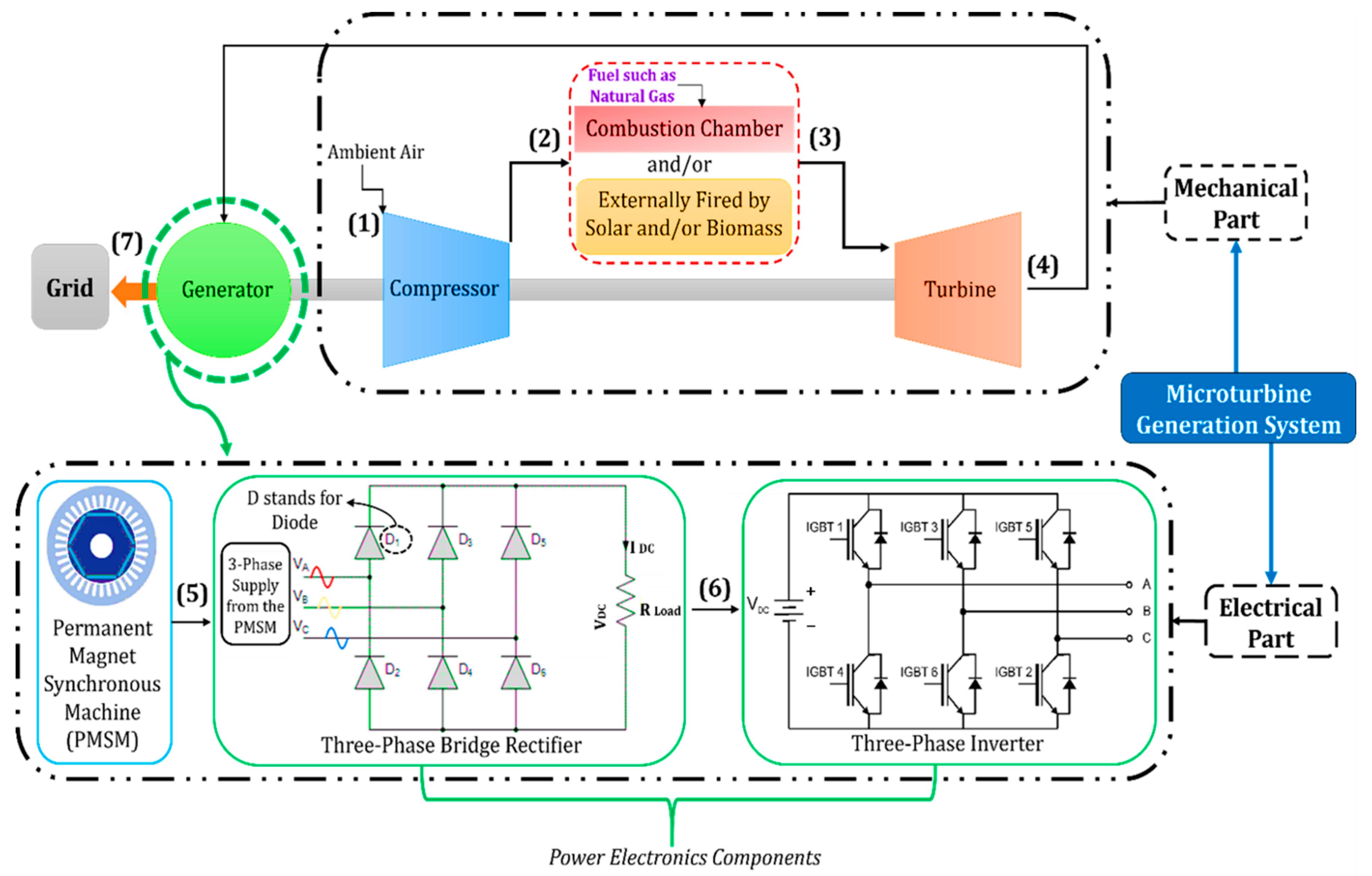
Microturbines are also referred to as micro gas turbines (MGTs). The basic components of a microturbine generating system can be categorised into two parts: mechanical and electrical. As seen in
Figure 1, microturbines’ mechanical components generally include an air compressor, combustor, and turbine. The electrical part is primarily composed of a permanent magnet synchronous machine (PMSM) and power electronics components such as two bidirectional power converters or a rectifier and an inverter. The compressor, turbine, and generator are all housed on a single shaft. The turbine drives the compressor and the generator simultaneously. The compressor of a microturbine pushes air into a recuperator (only in recuperative setup, as microturbines can also be simple, without a recuperator), which usually recovers heat from the exhaust gas. The pre-heated air provides the oxygen needed for the combustion process in the combustion chamber. The combustion products expand through the turbine, causing the shaft to rotate and generate electricity through the PMSM and the power electronic components. The letters A, B, and C in
Figure 1 symbolise the three phases of electrical power, with each phase being 120 degrees out of phase with the others. Numbers 1 to 7 reflect the flow of power transmission in the system.
Currently, published reviews in the literature discussed in detail the performance and operation improvements in microturbines from a mechanical and thermodynamic cycle and performance point of view. In contrast, the electrical part of microturbines was discussed hastily, focusing on certain rooms of improvements without proper discussion on the interference between electronic and mechanical elements, such as outlining the role of power electronic components in the controllability of specific parameters in microturbines. Also, to the best of the authors’ knowledge, there are no reported initiatives to utilise silicon carbide semiconductors in configuring the power converters of microturbines. This is presented in this paper. This paper explains elaborately, in an unprecedented way, the power transmission in the electrical part (PMSM and power electronics) of grid-connected microturbines, with emphasis on their additional importance in externally fired microturbines and the potential benefits of employing silicon carbide semiconductors instead of silicon in building up the topologies of the power converters in microturbines.
The paper is organised as follows:
Section 2 discusses the working concept of microturbines’ PMSM and power electronic components in depth for each element (rectifier, filters, and inverter). The main topology of microturbine power electronics is introduced. The grid synchronisation control technique used in power electronics for grid-connected microturbines is also presented in that section.
Section 3 traces studies on the electrical part of microturbines. This section reviews studies on control strategies of power electronics in microturbines, adopting different topologies of power converters, embracing different generator types such as the induction generator, and concluding potential deficiencies in these studies and where new studies should be directed.
Section 4 looks at the controllability prospects of the PMSM and power electronics in microturbines, particularly externally fired microturbines and emphasising the significance of having higher switching frequency in power electronics in boosting controllability and response time. In
Section 5, a suggestion to replace silicon (Si) with silicon carbide (SiC) in the construction of microturbine converters is made. The promising advantages of SiC over Si (higher switching frequency, lower cost, smaller component size, and less power loss) are also covered. Recommendations for future research are provided in
Section 6.
2. Electrical Part in Microturbines
The electrical part in microturbines consists of the permanent magnetic synchronous machine (PMSM) and the power electronic components. The most common topology of the power electronics in microturbines [
8,
9,
10] is shown in
Figure 2. This topology is adopted in TURBEC T100 [
11] and by most microturbines producers such as Ballard, Bowman and Elliott, Capstone Turbine Corporation, and General Electric [
12]. The topology is mainly comprised of a three-phase rectifier, three-phase inverter, and filters. Another main topology uses two bidirectional converters instead of a rectifier and an inverter [
13]. This eliminates the need for the additional rectifier and inverter for the motoring mode.
Figure 2 demonstrates a topology with two modes of operation: motoring and generation. During generation mode, the three-phase voltages from the PMSM flow through a passive rectifier and a grid-tie inverter, which feeds power into the grid. Another passive rectifier and inverter are used in the motoring mode to start the PMSM as a motor during the start-up operation. The design is less complicated than the architecture of the two bidirectional converters, but it increases the number of components in the system and, hence, its size. In addition, the necessity to switch between the two different circuits increases electrical losses. However, the architecture of the two bidirectional converters increases the complexity of both the conversion and control systems [
14]. In
Figure 2, N and S represent the magnet’ s north and south poles, respectively.
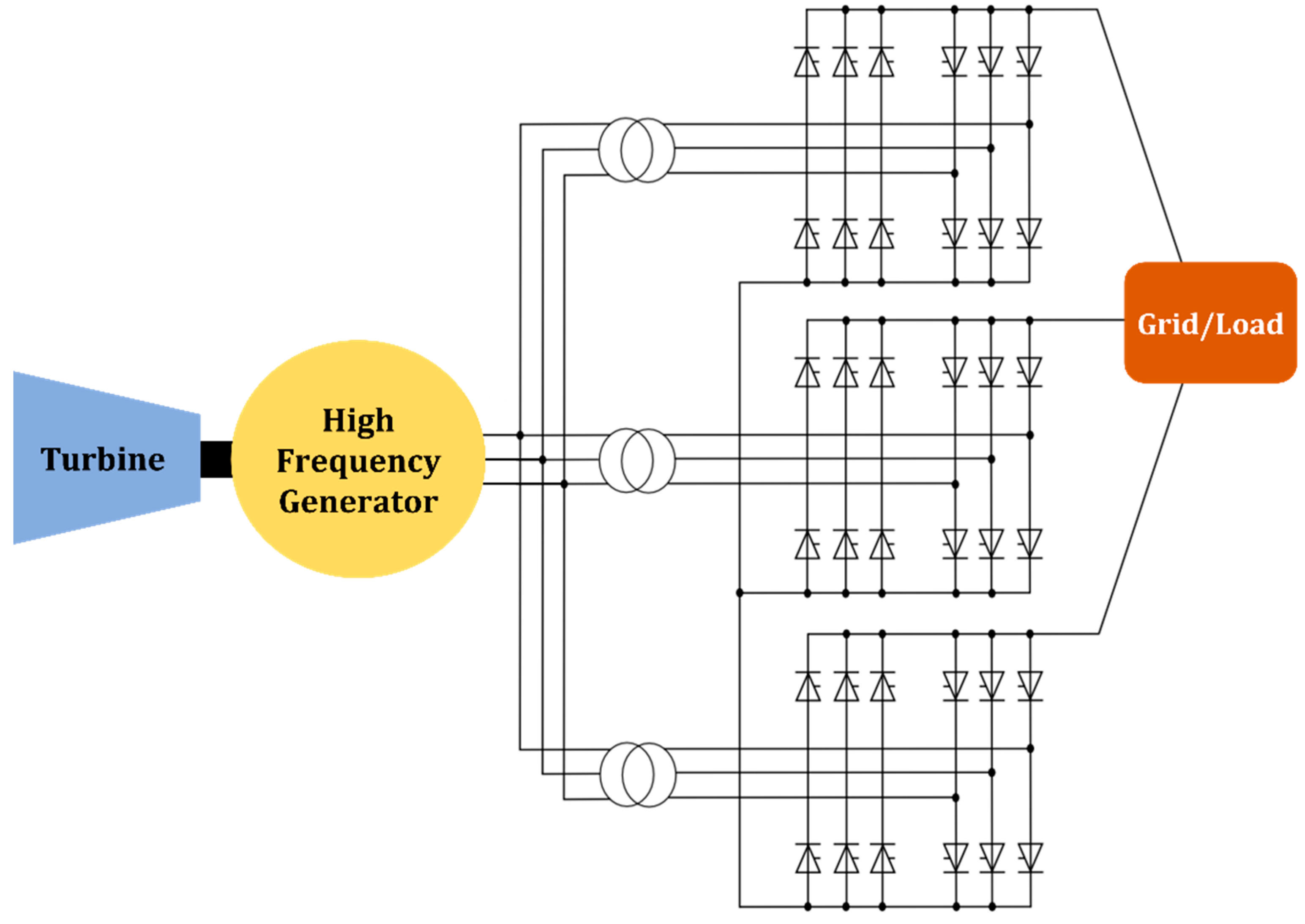
The high-frequency link converter (HFLC) is among other topologies used in microturbines [
12], as shown in
Figure 3. The HFLC microturbine generator supplies three-phase power to a three-phase rectifier that converts the power from Ac to DC. The DC is then fed into a single-phase, high-frequency inverter. The AC/AC converter transforms the single-phase, high-frequency voltage to a three-phase voltage with the frequency and phase required for a direct connection to the grid. Currently, no microturbine manufacturer is marketing generation systems that use the HFLC.
Figure 4 shows another configuration that uses a cycloconverter or a matrix converter instead of a rectifier and an inverter to connect the microturbine generator to the grid. These converters convert alternating current voltages at one frequency to alternating present voltages at another frequency with variable magnitude. As a result, they are also known as frequency changers. The disadvantages of these converters are that they have twice as many switches as the typical topology in
Figure 2. Also, there is no DC link to store energy. Without energy storage in the converter, any fluctuations on either side of the converter immediately impacts the other. These converters cannot be powered by a battery or any other source, unlike the typical topology in
Figure 2 or the HFLC. With a high-frequency link inverter, a cycloconverter can still be used for microturbines. Instead of converting the generator voltage to DC and then to high-frequency alternating current, a cycloconverter can directly convert the three-phase alternating current voltage to single-phase high-frequency alternating current voltage [
12].
2.1. Permanent Magnetic Synchronous Machine (PMSM)
The shaft interferes between the mechanical part of the microturbine and the generator. The shaft transfers mechanical power, in the form of shaft torque and rotational speed, to the generator, which is then converted into electrical power. The PMSM is an electric generator that generates a magnetic field using permanent magnets. The generator is made up of a stator (the stationary part) and a rotor (the rotating part). The stator has three sets of windings that are fixed in place at a 120° angle to one another. The rotor has permanent magnets that rotate inside the stator. The magnets generate a magnetic field that flows through the stator windings as the rotor rotates, producing an AC voltage in each winding. The PMSM then generates three voltages at 120°, out of phase with one another. The PMSM’s output voltage is highly alternating and cannot be connected directly to the grid. Therefore, power electronics converters are required after the PMSM to achieve grid frequency and voltages. The main difference between a PMSM and other generators is that the PMSM has a rotor with permanent magnets, eliminating the need for a separate excitation system (providing DC current to the rotor winding of a machine to create a magnetic field necessary for the generator operation). This simplifies the generator design and reduces its size and weight. In contrast, other generators, such as induction or synchronous generators, require a separate excitation system to create a magnetic field [
15]. The PMSM is capable of operating at very high speeds, resulting in a small package, as the size of the machine drops directly in proportion to the increase in speed [
16]. The PMSM in microturbines works as a generator in the generation mode and as a motor in the motoring mode.
2.2. Three-Phase Rectifier
The three-phase passive rectifier in microturbines uses six diodes to convert the AC three-phase output voltage from the PMSM to DC. A diode is a two-terminal electronic component that permits just one direction of electric current to pass. The rectifier has three diode pairs. Each pair is connected to one of the three phases of the alternating current voltage coming from the PMSM, as seen in
Figure 2. The diodes conduct and enable current to pass through when the input voltage is positive. The diodes do not conduct and prevent current flow when the input voltage is negative. As a result, the negative half-cycle of the alternating current voltage is effectively blocked, and the output voltage is transformed into a positive direct current voltage. The resultant DC voltage has some leftover AC ripple, which can be filtered further with filtering components [
17].
2.3. LC Filter
The rectified DC output of the rectifier is not constant but has a pulsating nature. This is because the rectified output is composed of a series of half-waves resulting in ripples. The ripple factor is a measure of the amount of AC variation present in a DC voltage. The ripple factor is an important parameter that describes the quality of the output from a rectifier, and it is typically expressed as a percentage. A high ripple factor indicates that the output signal has significant AC variation, which can cause problems such as fluctuations in the circuit’s performance, leading to errors or malfunctions. The ripple factor can be reduced by using smoothing techniques, such as an LC filter [
18], in the output stage of a rectifier. These components can filter out the AC component of the output signal, resulting in a smoother DC output with a lower ripple factor.
The inductor in an LC filter acts as a frequency-dependent resistor. It has a relatively low resistance at low frequencies, which allows low-frequency signals to pass through the filter without significant attenuation. However, the inductor has a higher resistance at high frequencies, which helps attenuate or filter out high-frequency signals. The inductor acts as a frequency-dependent “brake” that slows down or filters out high-frequency components of the signal. At low frequencies, the capacitor impedance is high, and the impedance of the inductor is low, so most of the voltage drop occurs across the inductor. As the frequency increases, the capacitor impedance decreases, causing the voltage to drop across the capacitor. This means that the capacitor dominates the filter’s behaviour at high frequencies [
19].
2.4. Three-Phase Inverter
The three-phase inverter converts the DC coming from the rectifier to AC. The output voltage of an inverter is a stepped waveform that simulates a pure sine wave. This stepped waveform is created by switching the DC voltage on and off at a high frequency. The switching is performed by a set of power transistors called insulated gate bipolar transistors (IGBTs). These switches turn on and off in a specific sequence, controlled by the pulse width modulation (PWM). To create a sine wave, the inverter’s IGBTs turn on one of the switches in the inverter circuit. After a specific period, the switch is turned off, and another switch is turned on, allowing the current to flow in the opposite direction. This process is repeated multiple times per second, creating a stepped waveform that simulates a sine wave. The speed at which the switches turn on and off determines the frequency of the output waveform. The higher the frequency, the more closely the stepped waveform resembles a pure sine wave, the less power loss, the faster response, and the smaller and more efficient inverter designs [
20].
2.4.1. Insulated Gate Bipolar Transistor (IGBT)
As shown in
Figure 5, the IGBT contains three terminals, the gate, emitter, and collector. The gate terminal of an IGBT is the input terminal that controls the current flow between the emitter and collector. The gate terminal is used to apply a voltage that determines whether the IGBT is in an on or off state. When a positive voltage is applied to the gate terminal with respect to the emitter, the IGBT turns on and allows current to flow between the collector and emitter. Conversely, when the voltage is removed, the IGBT turns off [
21].
The losses in an IGBT can be classified into two main types: conduction losses and switching losses. Conduction losses occur when the IGBT is conducting current. The conduction losses are proportional to the on-state voltage drop and the current flowing through the device. The on-state voltage drop is the voltage drop across the IGBT when conducting current. Switching losses occur when the IGBT is turned on or off.
2.4.2. Pulse Width Modulation (PWM)
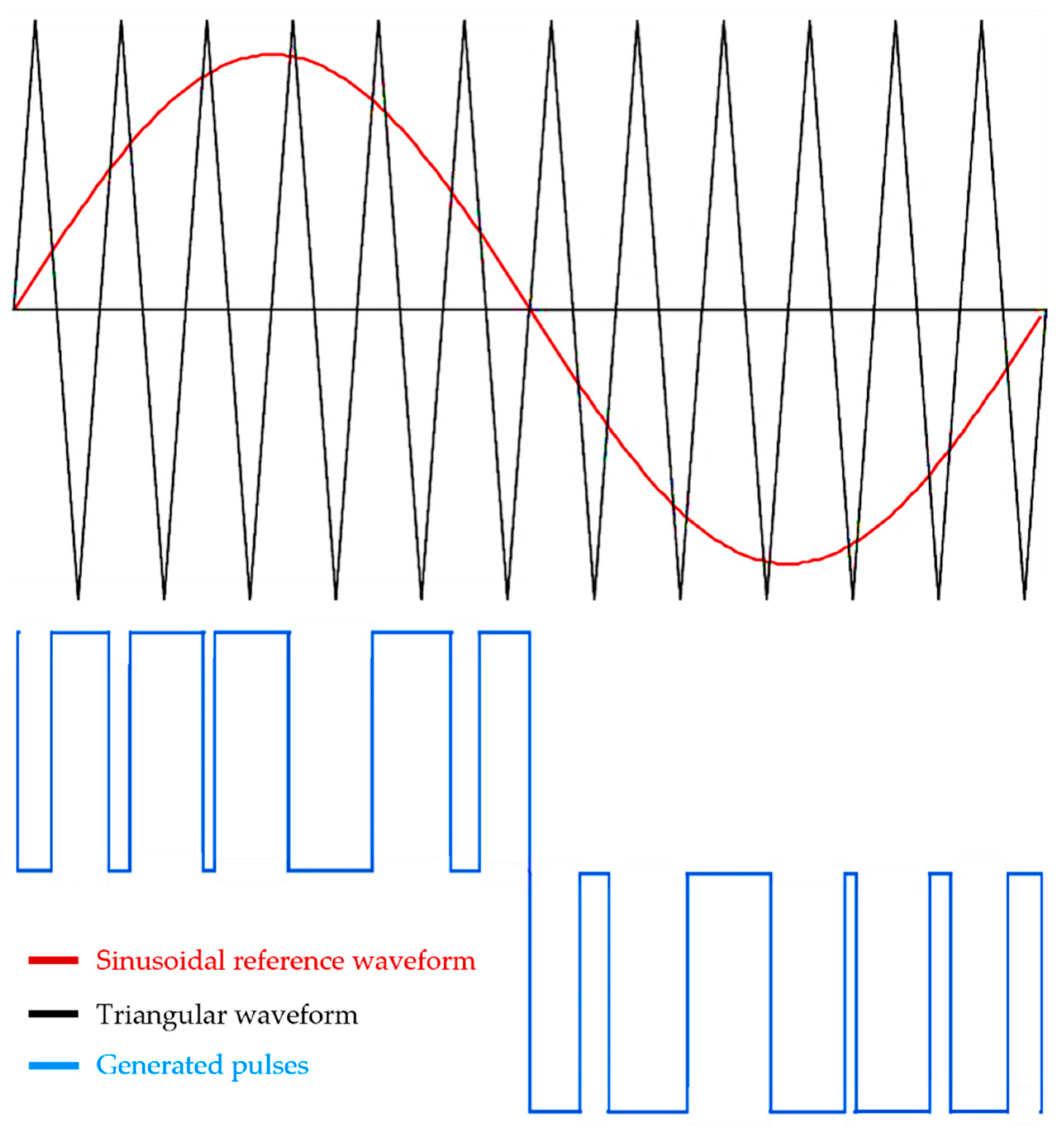
PWM is a technique used to control the output voltage of a three-phase inverter. It works by varying the width of the pulses in the output waveform, which changes the average voltage delivered to the load/grid. In a three-phase inverter, there are six IGBTs, with two transistors for each phase. The PWM technique works by switching these transistors on and off in a particular pattern that controls the output voltage. The PWM controller generates a reference waveform, which is typically a sinusoidal waveform with a fixed frequency. The PWM waveform is generated by comparing the reference sinusoidal waveform with the triangular waveform as seen in
Figure 6. When the reference waveform is higher than the triangular waveform, the IGBT is turned on, allowing current to flow through. When the reference waveform is lower than the triangular waveform, the IGBT is turned off, and no current flows through. The width of the pulse is varied by changing the frequency of the triangular waveform, which changes the time between the successive pulses. The width of the pulses can be varied to achieve a desired output voltage [
20].
2.5. LCL Filter
LCL filter is an electronic circuit used in power electronics systems to filter out high-frequency noise and harmonics from the output of a three-phase power inverter. The filter consists of inductors (L) and capacitors (C) arranged in an LCL configuration, as shown in
Figure 2, where the inductors are connected in series, and the capacitors are connected in parallel. The inductors are designed to block high-frequency noise and harmonics, while the capacitors are designed to shunt the noise and harmonics to the ground. The LCL filter creates a resonance circuit between the inductors and capacitors. The resonant frequency of the circuit is set to be higher than the highest frequency component of the noise and harmonics in the output of the power converter. When high-frequency noise and harmonics are present in the output of the power converter, they are shunted to the ground by the capacitors in the LCL filter. The inductors in the filter prevent the noise and harmonics from reaching the grid. The design and optimisation of LCL filters can be complex and requires careful consideration of factors such as the resonant frequency, damping, and component values.
2.6. Grid Synchronisation Control in Microturbines
It is necessary to understand Park and Clarke transformation before presenting the control technique for grid-connected microturbines. The Park and Clarke transformation is a mathematical transformation used in power systems to convert three-phase quantities to two-phase quantities. It is also known as the abc/dq transformation. The Park and Clarke transformation is used to ease three-phase system analysis by converting them to a two-dimensional reference frame [
22].
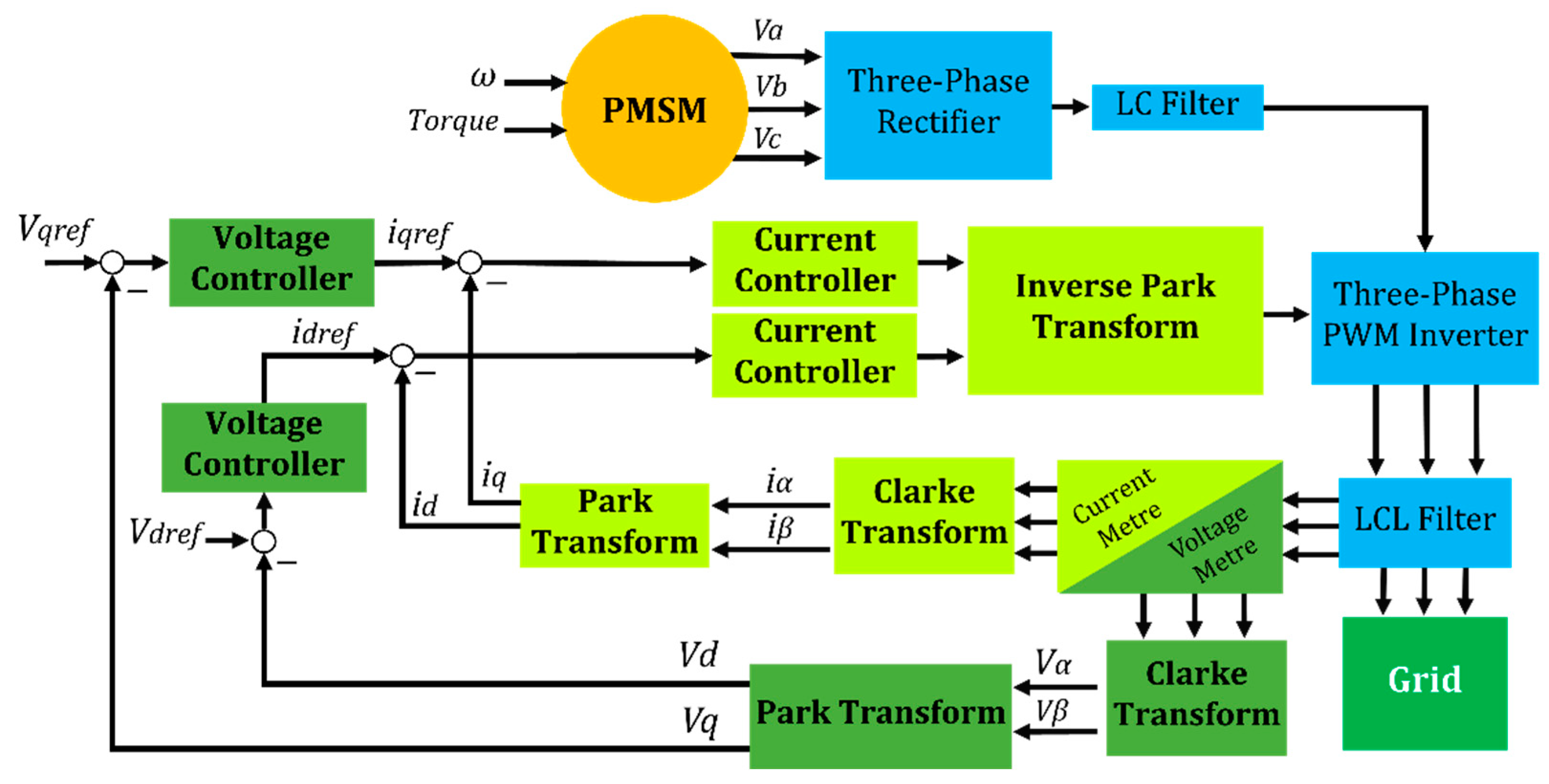
In grid-connected microturbines, the inverter output power needs to match the grid voltage and frequency. Handling the inverter output voltage and angle and maintaining the frequency at a predetermined level is accomplished by utilising two control loops: the inner current control loop and the outside voltage regulator loop, as shown in
Figure 7. The voltage controller generates the current reference signals for the current controller loop after taking error signals between the actual output voltage and the reference voltage. The current controller generates control signals, which are used to generate gating pulses for the inverter IGBTs through sinusoidal pulse-width modulation to control its output voltage [
9].
3. The Literature on the Electrical Part of Microturbines
Studies on the generator and power electronic components in microturbines and their control systems have been commonly covered in the literature, focusing on employing different control strategies, using other types of generators, designing different power electronics interface topologies, harmonics filters, and others.
The researchers of [
23] described and tested a novel technique for power electronic interface control of utility-interactive microturbine systems. Scholars of [
24] provided a model of a microturbine system with a process-variable control scheme for grid-connected mode and independent operation with variable frequency control, as well as a performance evaluation using a rural distribution system. The modelling and actual examination of sensor-less control of the permanent magnet synchronous machine (PMSM) in the start process of a 30 kW microturbine system without position and speed sensors was described in [
25]. The authors of [
26] presented a model of a microturbine system comprising a microturbine, synchronous generator, back-to-back power converters, and the appropriate control mechanisms. The model predictive control (MPC) approach is used in [
27] to control a microturbine’s inverter independent of load type. Furthermore, an active rectifier is employed to regulate the DC-link voltage. The simulation findings show that MPC is suitable for controlling high-frequency microturbines in stand-alone mode in various settings. They suggest a system that can function with constant, variable, non-linear, and unbalanced loads while maintaining output three-phase voltages unaffected by these variables. The pulse-width modulation (PWM) technique has also been discussed in the literature. The authors of [
28] employed a PWM rectifier to adjust the high-frequency electricity generated by a microturbine unit. Machine-learning-based controllers have also been presented in the literature. In [
16], the author proposes an artificial neural network (ANN)-based controller for a freestanding microturbine power plant. Furthermore, the article compares the performance of the microturbine while employing typical proportional-integral (PI) and ANN controllers.
The use of different power electronics interfaces and topologies was covered in several studies. In [
29], a grid-connected model of a microturbine system with a matrix converter and AC–DC–AC converters is described to assess the microturbine system’s electromagnetic transients. In [
30], a unique power electronic interface architecture for microturbine systems that combines three levels and two-level converters in a back-to-back connection was proposed. In [
31], the modelling of a back-to-back converter interface for a microturbine system is described. The efficiency of two power conditioning systems for a microturbine system, one with a passive rectifier, a boost converter, and an inverter and the other with an active rectifier and an inverter, was compared [
32]. Researchers in [
33] show extensive modelling and performance analysis of a microturbine system in a grid-connected/islanding mode of operation utilising a back-to-back converter interface.
Research on generators in microturbines was presented on different occasions. The authors of [
34] describe a high-efficiency drive system based on the current phase and revolving speed optimisation that employs a microturbine generator. Simulation research on the usage of induction generators in microturbine-based distributed generating systems was presented in [
35]. Using simulation findings and real-life data, the authors of [
36] investigated the load-following behaviour of a microturbine system with a synchronous generator in islanded and grid-connected modes.
Studies on filtering signals in the power transmission of the electrical part of the microturbine have also been presented. Research findings on the voltage and current harmonic characteristics of a three-phase, 480 V, 30 kW microturbine generator at varied load levels were presented in [
37]. The use of an active filter to minimise harmonic current in a high-speed microturbine system was investigated in [
38].
Although the preceding studies discuss various aspects of the electrical component in microturbines, it is still considered hastily examined, focusing on specific areas for improvement without proper discussion of the interaction between electronic and mechanical elements, such as outlining the role of power electronic components in the controllability of specific parameters in microturbines. Control strategies that employ the generator and electronics to control a pure solarised microturbine’s rotational speed and turbine inlet temperature (TIT) are discussed in [
14]. This is shown in the next section—however, more elaboration and a closer look at how these control techniques work is still needed. The following section examines the power electronics controllability capabilities in microturbines.
Artificial intelligence (AI)-based control systems in microturbines were also extensively reported in the literature. Previous work analysed and contrasted the controllers used in earlier studies for microturbines, which widely included conventional, optimised, and AI-based controllers. For further discussion on this, more can be found in reference [
39].
4. Electronics Controllability in Microturbines
Conventional fuel microturbines’ shaft speed and turbine inlet temperature (TIT) are normally controlled by regulating the fuel pumping into the combustion chamber. However, this is not an option in externally fired microturbines, such as pure solar microturbines. Hence, in externally fired microturbines, the control system must be accommodated to control strategies that do not rely on fuel (thermal input) regulation. Solar tracking may compensate for the need for a fuel regulator to control the thermal input to the system in the case of solarised microturbines. However, this technique is impractical since the tracking movement mechanism has a much slower dynamic response than the microturbine dynamic response. Different operating strategies for a pure solarised microturbine were examined in [
14]. The maximum permitted power (MPP) technique has been demonstrated to be the most effective operation strategy for keeping the microturbine’s operating parameters within safe limits while producing maximum power at any direct normal irradiance (DNI) value. This is accomplished by maintaining the turbine at the rotational speed that produces the most power for any given DNI. Since controlling the shaft speed through fuel or thermal input regulation is not possible in the system, the authors proposed using the generator and power electronics to control the microturbine shaft speed. This was briefly explored in that study. A more in-depth comprehensive on how the permanent magnetic synchronous machine (PMSM) and electronics can possibly control certain parameters, such as shaft speed and torque, is needed either in pure solarised microturbine systems or comparable instances.
The field-oriented control (FOC) technique is a common control technique used in PMSMs to control rotational speed and torque through controlling the magnetic flux the PMSM produces.
Figure 8 depicts a block diagram of FOC. Using the Clarke and Park transforms, the three-phase stator currents (ia, ib, ic) of the PMSM are measured and converted from the stationary reference frame (abc) to the rotating reference frame (dq). The converted variables can be separated into two components by transforming the stator currents to the dq reference frame: the q-axis component (iq) and the d-axis component (id). The iq component is in charge of producing motor torque, while the id component is in charge of producing magnetic flux. There are two control loops: one for controlling the id component and another for controlling the iq component. In the speed controller, which generates the reference torque (iqref), the PMSM speed is measured and compared to the reference speed. The d-axis component reference (idref) is determined by the desired output torque, which is estimated using a mathematical model that considers the motor’s physical parameters, namely, speed, voltages, and currents. The control signals are then applied to the motor’s windings to produce the desired torque and speed [
40]. If the d-axis component reference (idref) is set to zero, the FOC only controls the q-axis component of the motor. This means that the control maintains a constant magnetic flux in the motor’s stator, resulting in a constant speed if, and only if, the motor’s load remains constant. The load, on the other hand, is a representation of the torque. As a result, controlling the torque means having the ability to control the rotational speed even when the d-axis component reference is set to zero.
Another control strategy that controls the rotational speed and torque of the PMSM is called voltage vector control (VVC). In VVC, the control system adjusts the voltage vectors applied to the PMSM’s stator windings to achieve the desired torque and speed output. The voltage vectors are represented as space vectors in a two-dimensional vector space, and their magnitudes and angles are adjusted to achieve the desired torque and speed [
41]. VVC operates by comparing the desired PMSM torque and speed with the actual motor torque and speed and adjusting the voltage vectors applied to the motor’s stator windings to achieve the desired output. An example of one more control strategy that is used to handle the torque of the PMSM is called direct torque control (DTC). This method directly controls the motor’s torque and flux without requiring a separate current control loop. Instead, DTC uses a look-up table, which contains precomputed values for the inverter switching states for each possible combination of torque and flux values, and selects the appropriate voltage vector based on the motor operating conditions [
42].
Table 1 outlines a comparison between FOC, VVC, and DTC control methods, highlighting their key differences.
The switching frequency is the most influential concern in the PMSM and electronics controllability: the higher the switching frequency, the faster response to input and load variations and, therefore, the more reliable the control system. Higher switching frequency decreases the settling time (the time it takes for the output of a control system to stabilise after a change in the input). It, therefore, enhances the system’s transient response. Increasing the switching frequency of power electronic devices, in addition, enables the use of smaller and lighter components, such as semiconductors, inductors, and capacitors, which can reduce the system’s overall size and weight. At higher switching frequencies, the duration of each switching cycle for semiconductors decreases, and the switch requires less time to transition between the on and off states. As a result, the time the switch spends in an on-resistance state (during the transition between the on and off states) decreases, reducing switching losses. This is because the energy lost during the transition is proportional to its duration, so shorter transitions result in lower switching losses. The reduction in peak current levels also contributes to reduced switching losses at higher frequencies since the current waveform is typically smoother at higher frequencies, resulting in lower peak current levels. Since switching losses are proportional to the current, reducing peak current leads to decreased switching losses.
5. Silicon Carbide in Power Electronics
The predominant type of switch devices utilised in microturbine converters is the silicon (Si)-insulated gate bipolar transistor (IGBT) rather than other types of switch devices such as a metal–oxide–semiconductor field-effect transistor (MOSFET), junction–gate field-effect transistor (JFET), and a bipolar junction transistor (BJT) [
12]. However, silicon carbide (SiC) devices are a new generation of efficient semiconductors that have found widespread use in a variety of applications in recent years due to their ability to switch at greater frequencies [
48,
49]. As far as the authors are aware, despite their promising features, no documented efforts have been made to replace Si with SiC in the power electronic components of microturbines. This may be due to the recent appearance of SiC IGBTs in the market, which is still being developed and researched [
50]. Also, there could be challenges to using the already introduced SiC devices, such as MOSFETs and BJTs in microturbines, as their switching speeds are still slow compared to IGBTs. The replacement of silicon IGBTs with silicon carbide IGBTs for a three-phase inverter for an aircraft application was studied in [
51]. The results show lower power losses and an enhancement in the efficiency of the inverter from 86% to 92%.
With the anticipated benefits of SiC’s greater switching frequency, it is critical to demonstrate the potential benefits of using these semiconductors in microturbines. Since there have been no recorded attempts to implement SiC in microturbines, this work examines studies that compared SiC and Si in contexts other than microturbines, leaving unanswered the question of whether or not silicon carbide power converters would be advantageous in microturbines relative to silicon-based converters in terms of switching frequency, controllability, power loss savings, power density increase, better thermal endurance, and overall cost reduction.
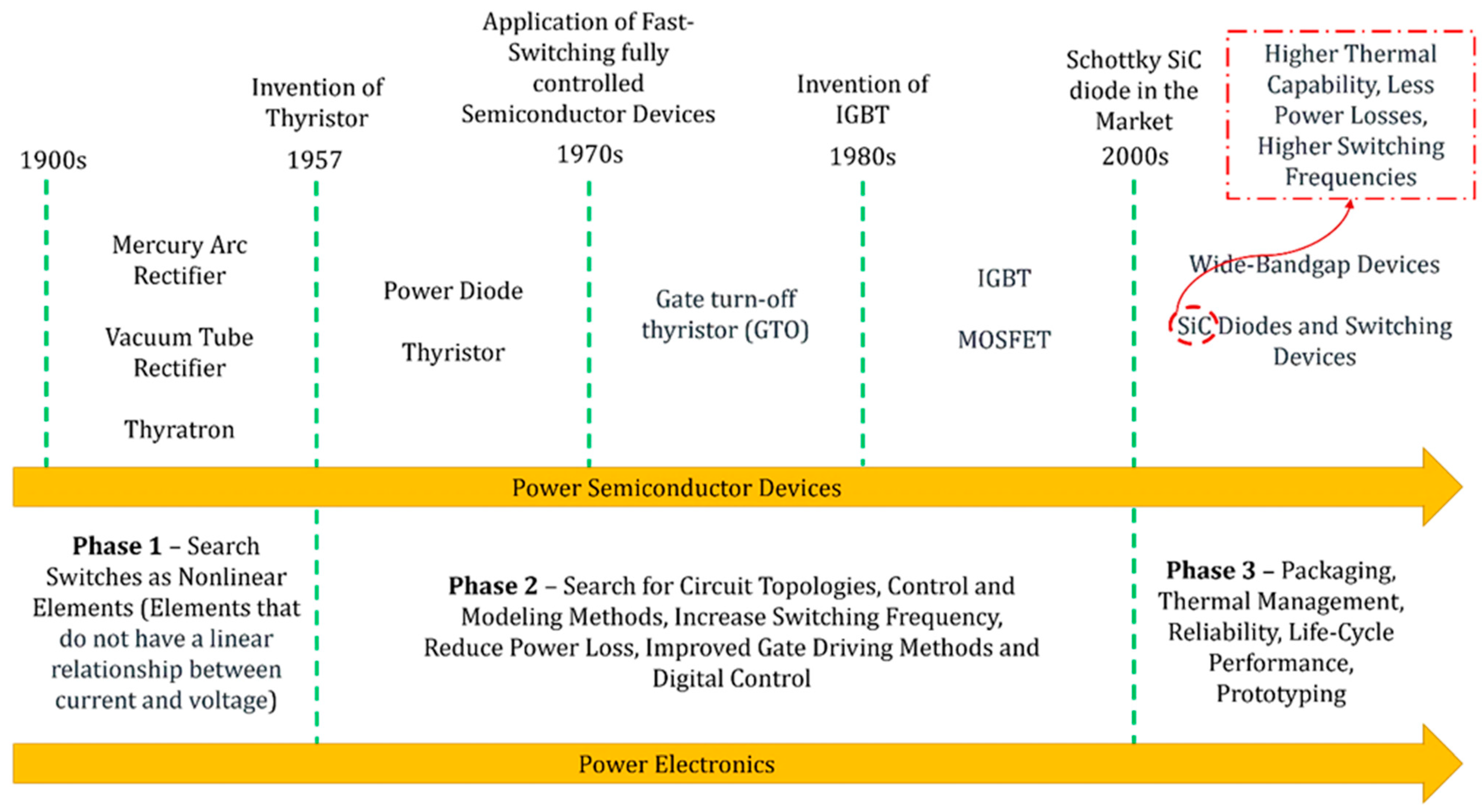
High switching frequency, low power losses, and excellent thermal stability make silicon carbide attractive for power converters. The evolution of power semiconductors and electronics [
52] is depicted in
Figure 9.
A comparison of the conduction and switching losses are presented in [
53]. The semiconductor losses of a SiC MOSFET-based inverter with a Si IGBT-based inverter are compared. The comparisons are performed adopting the system parameters listed in
Table 2.
It has been demonstrated that the switching and conduction losses of the SiC MOSFET-based inverter are much less than that of the Si IGBT-based inverter, as depicted in
Figure 10.
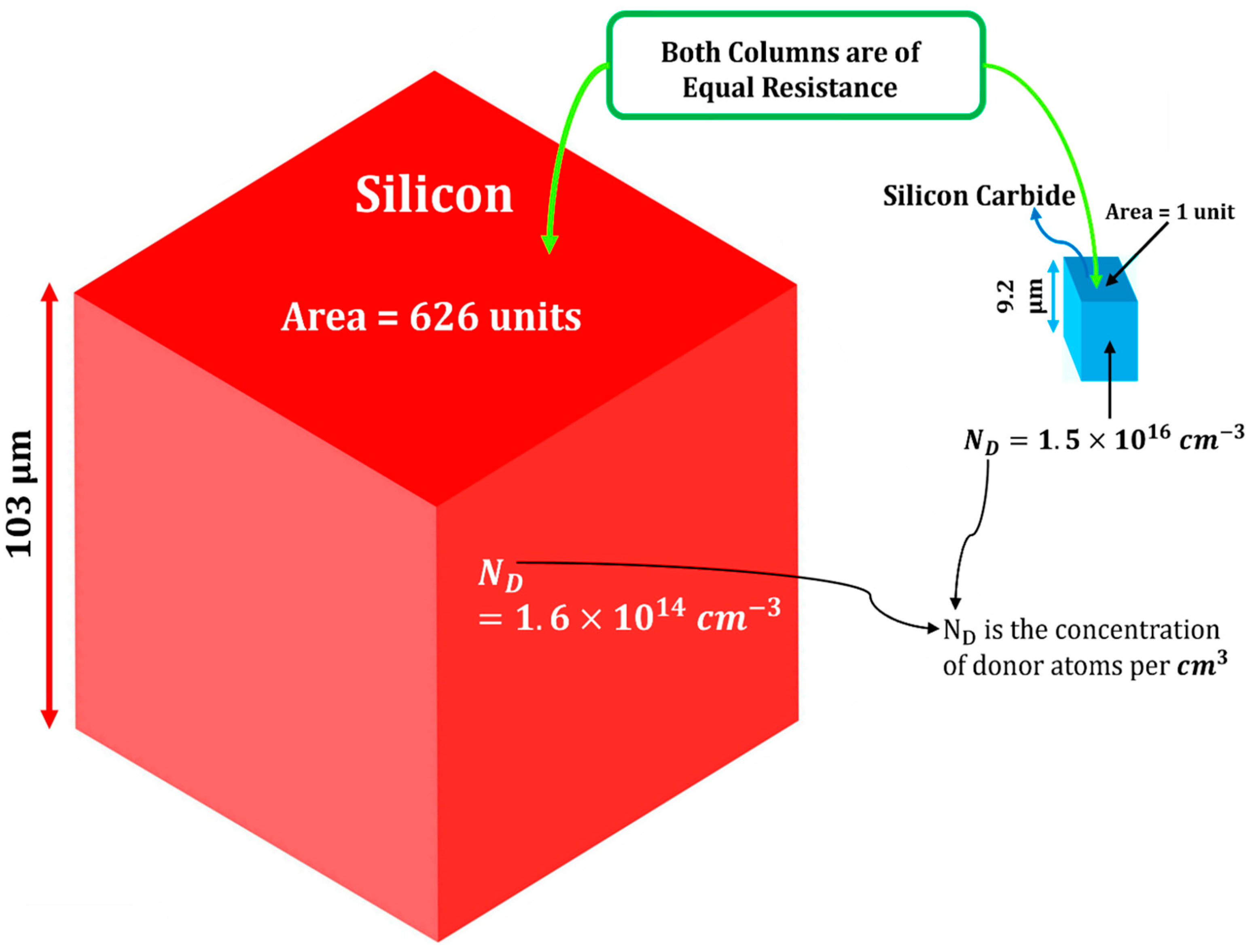
SiC materials, in general, provide a marked reduction in device footprint when compared to Si materials. This is due to the fact that the layer dimensions of SiC-based devices are substantially smaller than those of Si-based devices.
Figure 11 illustrates a comparison between the layer size of a 1200 V MOSFET [
54].
Table 3 contains additional comparative characteristics for the same device depicted in
Figure 11. These parameters are presented for the same layer resistance and at a junction temperature of 25 °C.
Compared to Si, SiC materials provide a significant decrease in device footprint. In addition, the thermal resistance of SiC materials is higher than that of Si materials. The thermal resistance of a material is directly related to the concentration of donor atoms (ND). Thermal resistance increases with increasing ND [
55]. As shown in
Figure 11, SiC materials have higher ND than Si materials. The higher a material’s thermal resistance, the higher the junction temperature it can withstand. This demonstrates why SiC devices would have better thermal stability and a higher operating temperature than Si devices.
An experimental comparison of three power devices, namely, 6.5 kV/25 A Si IGBT, a 6.5 kV/15 A SiC JFET, and a 6 kV/26 A SiC developed prototype by Infineon and called FREEDM, is presented by the authors of [
56]. These devices were compared in terms of their power consumption, size, and cost. Parameters for the three sample devices are summarised in
Table 4, which includes the die size, blocking voltage, rated current, and drain-source on resistance.
As shown in
Figure 12, switching losses, conduction losses, device sizes, and costs are compared. The FREEDM Super-Cascode has the lowest switching loss, modest conduction losses, and the lowest device cost; nonetheless, its device size is one of its drawbacks. The 6.5 kV SiC JFET has balanced device size, conduction loss, and switching loss. However, the device cost is considerably high. The 6.5 kV Si IGBT is inexpensive and compact. However, the losses, particularly the switching losses, are unsatisfactory.
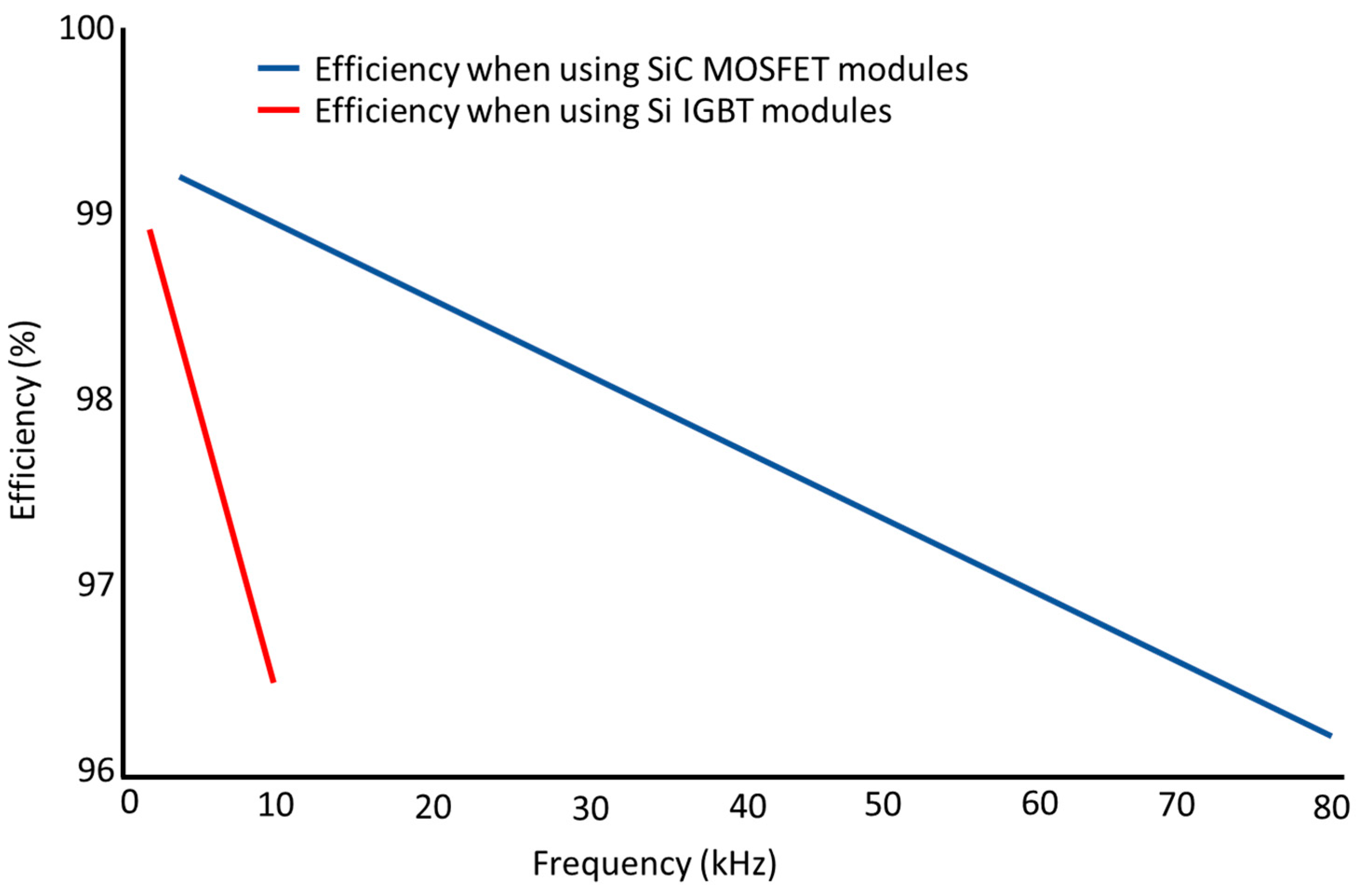
The authors of [
57] presented a comparison of efficiency for a three-phase converter based on SiC MOSFETs and Si IGBTs. The parameters of the used SiC and Si modules are shown in
Table 5. As shown in
Figure 13, when the switching frequency is 20 kHz, the efficiency of the SiC system surpasses 98.6 per cent. However, the Si IGBT converter’s efficiency decreases to 96.5 per cent at 10 kHz at the same power level. The efficiency of the 100 kW SiC MOSFET module converter approaches 96.2 per cent when the switching frequency is 80 kHz. This demonstrates how employing SiC MOSFET modules may improve the efficiency of medium/low-voltage high-power systems and allow for high switching-frequency operation.
In microturbines, the switching frequency ranges between 4–25 kHz [
12]. However, with the introduction of SiC devices, higher switching frequencies may be employed to increase their efficiency.
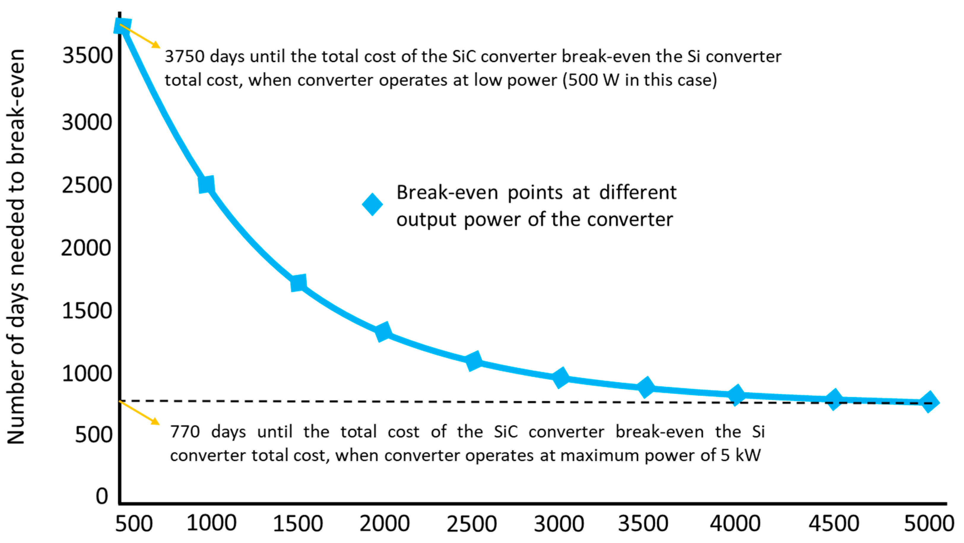
An example of a cost comparison between Si and SiC power converters is presented in [
58]. The two converters used in this article are Si IGBT-based and SiC JFET-based converters. Consideration has been given to both initial and continuing expenditures. The initial investment consists of the price of the two converters’ components.
Table 6 provides an approximation of this.
SiC JFET converters cost more than twice as much as Si IGBT converters. However, the cooling requirements (heat sink) of the Si IGBT converter are greater than those of the SiC JEFT converters. The break-even point for the overall cost, including the running cost of the two power converters with different output powers, has been computed. It is observed that if a power supply operates at maximum capacity for 24 h a day, the additional investment in the SiC-based converter is repaid in around 770 days, as seen in
Figure 14. Therefore, using SiC-based converters in microturbines may be beneficial to reduce the overall cost of the microturbine unit, as the lifespan of the microturbine ranges from between 8 to 20 years of operation [
59,
60].
6. Recommendations for Future Research
Regulating fuel/thermal input is not an option for microturbines fired externally to control their rotational speed. As a result, either existing control methods such as field-oriented control (FOC), vector voltage control (VVC), or direct torque control (DTC) need to be adopted, or other control techniques that do not rely on thermal input regulation should be used or developed. The use of permanent magnetic synchronous machine (PMSM) and power electronics as controllers for key variables in microturbines, such as rotational speed and torque, would increase interference between mechanical and electronic components. This can be extended even to internally fired microturbines. In other words, this means employing the PMSM and electronics to control shaft speed and torque in internally fuelled microturbines, although their rotational speeds can be controlled using a fuel regulator. This is to compare the two control systems in terms of time response, cost, size, and losses to determine whether there are any benefits to using the PMSM and electronics to regulate the rotational speed and torque of microturbines, even if they are internally fired and can be regulated through other means such as fuel regulation. It is also critical to consider future research exploring artificial intelligence (AI)-based control systems in microturbines. AI-based control approaches rely on traditional control strategies, such as FOC, PI, and others. In other words, AI in control may be thought of as an extension and augmentation of existing control approaches to improve control performance, adapt to changing operating conditions, and optimize control parameters.
There is also the suggestion that microturbines employ silicon carbide (SiC) switching devices rather than silicon (Si) ones. Further research is needed to compare the performance of the microturbine with silicon carbide versus silicon power electronics. This can be accomplished by contrasting them in terms of switching frequency, control system reliability, and power loss. On several occasions, SiC demonstrated higher switching frequencies and lower power loss. This shows an opportunity for these interesting qualities to be incorporated into microturbines.
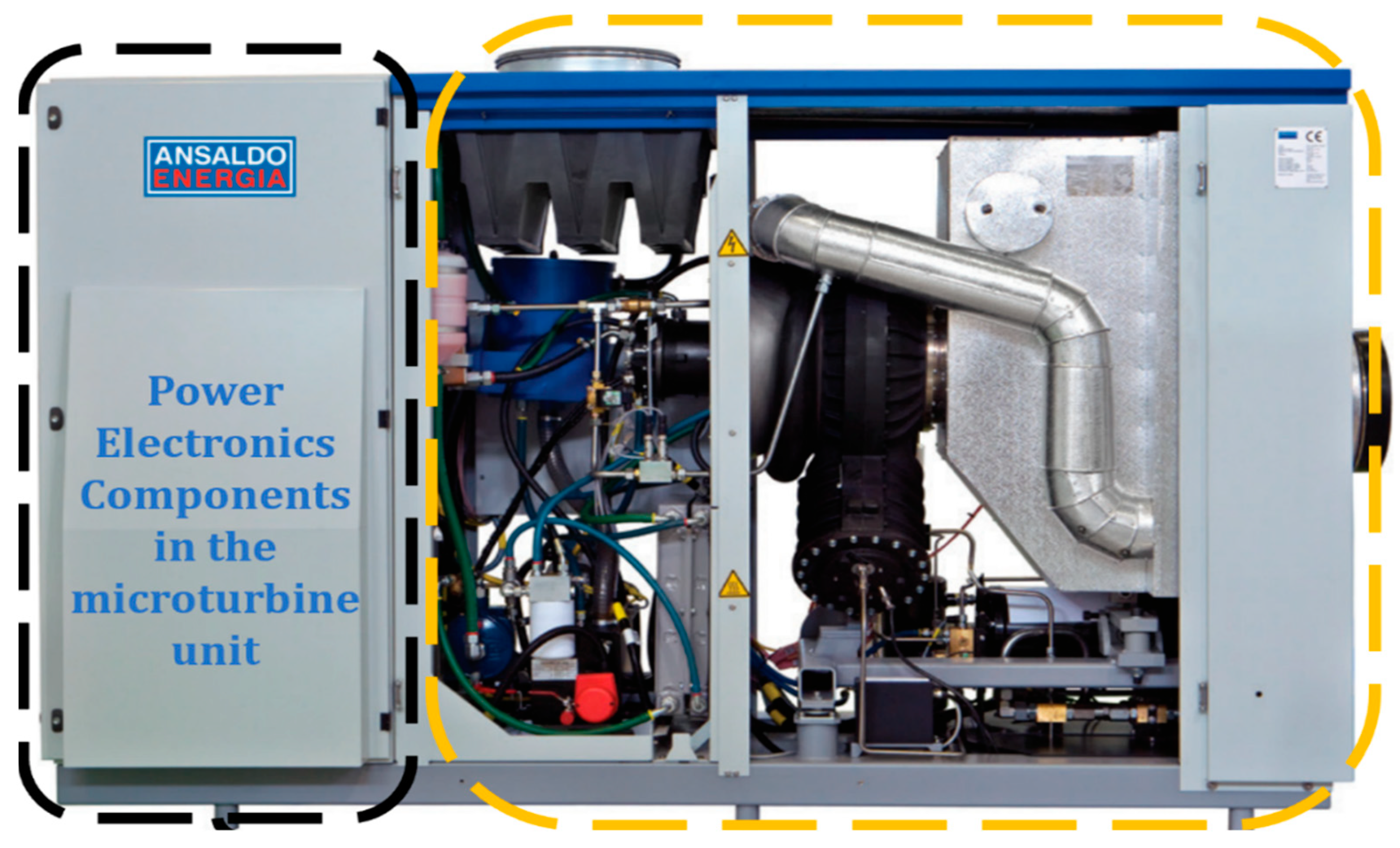
Size reductions were also observed in SiC devices. In microturbines, almost thirty per cent of their total size is taken up by its power electronics. Therefore, any reduction in the size of those components will have a considerable impact on the overall size of the microturbine. The Ansaldo Energeia T100 microturbine is depicted in
Figure 15, displaying the power electronics with the entire microturbine unit, which enables a clear visual comparison of their respective sizes.
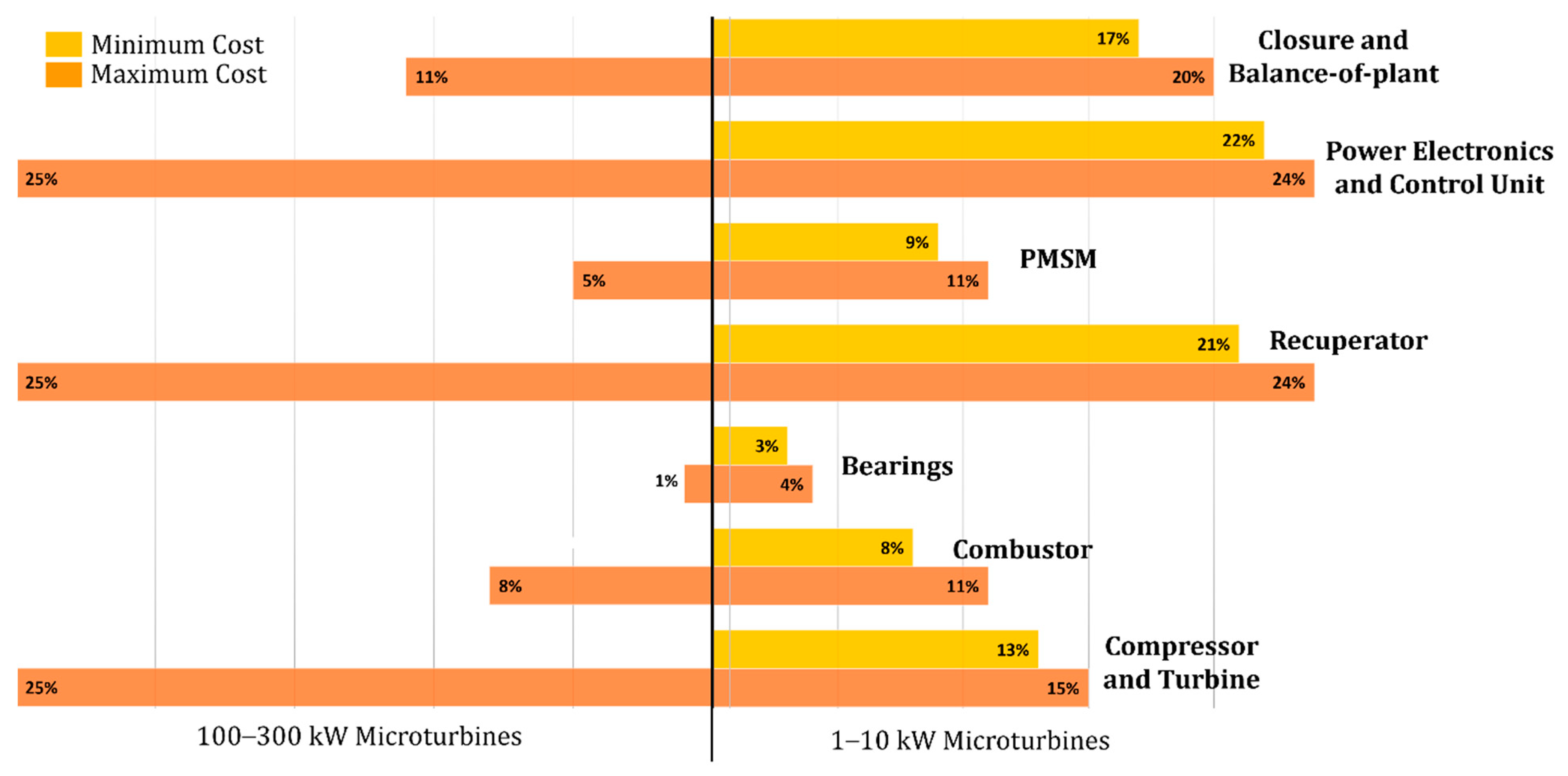
The costs of the generator, power electronic components, and the control unit in microturbine units are considerable.
Figure 16 demonstrates the cost distribution of the different components of the microturbine units with power ranging from 1–300 kW. It is observed that the cost of the electrical components comprises approximately 30–35% of the total unit cost of the microturbine [
61]. This suggests that cutting costs on power electronics components will have a substantial impact on reducing the microturbine’s total cost. In general, SiC devices show a lower total cost than Si ones. Therefore, using SiC in the power electronics of microturbines may significantly help reduce the overall unit cost of the microturbine unit.
The initial cost of SiC modules is usually higher than Si ones. However, it has been shown in the literature that the cost of SiC-based electronics can break even against the cost of Si-based electronics in around two years of operation when considering the levelised cost of electricity (LCOE) [
58]. Therefore, replacing Si with SiC in the electronics of microturbines is promising, given that the lifespan of the microturbine ranges from between 8 to 20 years of operation [
59,
60]. The below equation illustrates the LCOE [
62].
where:
Total lifetime costs of the power plant include all the costs associated with building, operating, and maintaining the power plant over its lifetime, such as capital costs, fuel costs, and operation and maintenance costs;
Total lifetime electricity generation is the total amount of electricity the power plant is expected to produce over its lifetime.
Future research on comparing the LCOE for microturbines based on SiC and Si is recommended.
7. Conclusions
Microturbines are practical for flexibility and new power market orientations since they can operate on a variety of fuel sources, both internally and externally. However, issues concerning the microturbine control system, unit cost and size, and its power electronics need to be addressed. For instance, maintaining the shaft speed by thermal input regulation is no longer an option when microturbines are externally fired, such as solarised microturbines. This review paper discussed alternate control methods employing the permanent magnet synchronous machine (PMSM) and electronics to control the shaft speed and torque. Future research into the implementation of such control techniques in microturbines is recommended. Understanding the power transmission through the electrical part of the microturbine (PMSM, rectifier, and inverter) is crucial for the implementation of such control strategies in microturbines. Therefore, this review paper provided a thorough review of power conversion in each component of the electrical part of the microturbine. It is also intended to provide other researchers with a comprehensive reference of information regarding understanding the power transmission in power electronics and the PMSM in microturbines. The existing literature on the electrical performance of microturbines has also been reviewed, identifying areas where progress has already been achieved as well as those where more research is still required. The importance of having higher switching frequencies for the electrical part of the microturbines has been discussed. A higher switching frequency results in less power loss, cost, and unit size, and a more reliable control system. It is recommended to use silicon carbide instead of silicon in building up the topologies of the microturbines electronics, as silicon carbide has shown higher switching frequencies in many applications. Among other challenges is that the electrical components of microturbines account for one-third of the unit’s overall size and cost. This means that reducing the size and cost of the electronics tends to reduce the entire unit size and cost. In applications other than microturbines, silicon carbide outperformed silicon in terms of size and levelised cost of electricity. Investigating silicon carbide in microturbines is worthwhile to see whether it provides such promising benefits to the microturbine unit. Due to the fact that silicon carbide has not been tested yet in microturbines, the suggestion for future work to replace silicon with silicon carbide in microturbines was based on research comparing the switching frequency, size, cost, thermal durability, and power losses of silicon and silicon carbide components in applications other than microturbines.
