Abstract
Natural gas-fired combined cycle plants are nowadays one of the most efficient and environmentally friendly energy complexes. High energy efficiency and low specific emissions are achieved primarily due to the high average integral temperature of heat supply in the Brayton–Rankine cycle. In this case, the main sources of energy losses are heat losses in the condenser of the steam turbine plant and heat losses with the exhaust gases of the waste heat boiler. This work is related to the analysis of the thermodynamic and economic effects in the transition from binary to trinary cycles, in which, in addition to the gas and steam–water cycles, there is an additional cycle with a low-boiling coolant. A method for the feasibility study of a waste heat recovery unit for trinary plants is proposed. The schematic and design solutions described will ensure the increased energy and economic performance of combined cycle power plants. Based on the results of the thermodynamic optimization of the structure and parameters of thermal schemes, it was found that the use of the organic Rankine cycle with R236ea freon for the utilization of the low-grade heat of a trinary plant’s exhaust gases operating from a GTE-160 gas turbine makes it possible to achieve a net electrical efficiency of 51.3%, which is a 0.4% higher efficiency for a double-circuit combined cycle gas turbine plant and a 2.1% higher efficiency for a single-circuit cycle with similar initial parameters. On the basis of the conducted feasibility study, the parameters and characteristics of the heat exchangers of the regenerative system of the waste heat recovery unit are substantiated. The use of plain fin-and-tube heat exchangers in the regenerative system of the utilization cycle is the most promising solution. It was found that the level of allowable pressure loss in the regenerator of 10 kPa and the degree of regeneration of 80% allow for maximum economic efficiency of the waste heat recovery unit.
1. Introduction
The continuous global population growth and active industrialization are the reasons for the significantly increasing demand for energy resources: both hydrocarbon and renewable. This is evidenced by the data obtained from the International Energy Agency [1], according to which, over the past 20 years, the demand for primary energy sources has increased by more than 42.5%, and according to forecasts, this trend will continue in the future (Figure 1). At the same time, the issue of limited fossil resources is acute, while the pace of the development of renewable energy sources is currently insufficient to meet the goals of sustainable development [2].
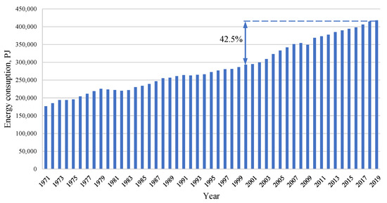
Figure 1.
Dynamics of primary energy resources consumption.
These factors determined the presence of a trend toward the rational use of natural resources and energy saving. In many countries, improving the energy efficiency of the main sectors of the economy is enshrined at the legislative level and is a key area of development. Thus, the development of scientific and technical solutions in the field of energy efficiency is becoming an extremely popular area.
Today, most of the electrical and thermal energy in the world is generated at thermal power plants, with its share in generation being more than 60%. The combined cycle gas turbine (CCGT) process remains the most efficient fuel energy conversion technology at the moment, the net electrical efficiency of which can reach 64% [3,4]. Such a high level is due, first of all, to high initial parameters (the temperature at the gas turbine unit (GTU) inlet can reach 1650 °C [5,6]).
An increase in the efficiency of steam–gas plants can be achieved by increasing the level of the initial cycle parameters; however, this method is severely limited by the thermal stability of materials for the manufacture of high-temperature stages of gas turbines and blade cooling technologies. Another option is to reduce losses in cold sources, primarily in the steam turbine condenser. In addition, a promising trend is found in the deep recovery of the heat from exhaust gases.
To date, steam–gas plants operating on a binary cycle have been widely used, in which the steam turbine part can be represented as one, two and three coolant circuits. The main energy losses in these plants are observed in the condenser of the steam turbine plant. The most obvious method to reduce them is the in development of a system for the regenerative heating of the water coolant. However, it should be noted that an increase in pressure in the regenerative bleeding off the main system, along with an increase in the number of regenerative heaters, will lead not only to a decrease in heat losses in the condenser, but also to a significant increase in the exhaust gas temperature at the outlet of the waste heat boiler (due to an increase in the feed water temperature at the inlet to the waste heat boiler) and to an increase in energy losses accordingly [7,8]. Therefore, the developed regeneration system is most often not used at CCGT.
At the same time, additional downstream cycles can be used to recover the low-temperature heat of the CCGT exhaust gases. Thus, the work [9] considers the addition of an organic Rankine cycle (ORC) to a combined cycle plant for the additional generation of electricity by using the heat of exhaust gases. When considering Orenda OGT1500 gas turbine, the exhaust gas temperature from the waste heat boiler was 188 °C, which makes the use of ORC justified. When using R134a coolant, ORC efficiency is 45.47%, and when using R123 coolant, it reaches 45.56%.
Tsibulsky and Galashov in [10] considered the use of ammonia, butane, pentane, R236fa and R245fa to recover the heat of a condensate after the pump and the latent heat of the steam undergo condensation after utilizing a CCGT steam turbine in the organic Rankine cycle with a regenerator. When using NK-36ST CCGT and a single-circuit waste heat boiler with initial parameters of 16 MPa and 440 °C, the use of ORC allows for the efficiency of more than 60% at a condensation temperature in the low-potential cycle of less than 0 °C, but this can be reliably achieved only by using air-cooled condensers and only if an organic working body is used as the working body in the ORC. The highest cycle efficiency was achieved using pentane in the ORC, followed by butane, R245fa and ammonia. The same authors [11] reviewed a CCGT with a low-potential cycle using pentane, butane, R365mfc, RC318, R236ea, R236fa, R123, R245ca and R245fa. It has been established that the most effective coolants are pentane and R365mfc. The results showed that the CCGT efficiency strongly depends on the substance condensation temperature. For example, when using pentane, when the condensing temperature is lowered by 10 °C, the cycle efficiency increases by about 0.71%.
Additionally, the article [12] considered the use of n-pentane, R134a, fluorocarbon, FP-72, water vapor and air in the organic Rankine cycle for heat recovery at initial parameters of 1.5 MPa and 160 °C. All of the low-boiling coolants considered compared to water vapor and air have a lower speed of sound and higher rates of increase in specific volumes during expansion in the turbine, which makes it necessary to increase the number of its stages.
Additionally, the recovery of the low-grade heat of exhaust gases was considered in the article [13]. In the trinary cycle, an NK-37 gas turbine was used as a heat source for two low-temperature cycles. In the first cycle, a single-circuit benzene-fired waste heat boiler was used, and in the second, the heat from the flow from the turbine and the latent heat in the condenser was used. In the second cycle, butane was chosen as the coolant and regeneration was carried out. The use of such cycle made it possible to increase the efficiency by up to 62.6%.
The paper [14] presents a comparison of the prospects for using ORC and S-CO2 cycles to recover heat from industrial gas turbines at thermal power plants. Carbon dioxide cycles can be more energy efficient, but due to the high capital costs for the construction of these plants, they are not widely used. In this regard, organic Rankine cycles are more promising for energy generation. The paper [15] considers the issue of the joint use of gas turbines and ORC for a more efficient electricity generation from geothermal sources. The efficiency can be even higher by increasing the temperature of heat supplied for the cycle.
The paper [16] presents an analysis of a power plant operation with a gas turbine and ORC. It was found in the paper that the outdoor air parameters significantly affect the plant efficiency, primarily due to the impact on the air condenser operation.
The issue of selecting optimal schemes solutions for trinary power plants remains poorly studied today; a wide variety of low-grade heat recovery cycles necessitates their comparison for the case of their use in conjunction with CCGP plants. In this case, the selection of schemes parameters should be determined not only by the energy efficiency of power generation, but also by economic efficiency. Despite the large number of studies devoted to the use of cycles with low-boiling coolant for heat recovery, the issue of using such installations in the electric power industry, in particular in CCGT power plants, remains poorly explored. There is not enough information on the energy and economic efficiency of the trinary power plants operation; therefore, there are no recommendations on how to select flow schemes and design parameters.
This paper is devoted to the feasibility study of a regenerator flow scheme and parameters for trinary energy cycles. To determine the optimal set of a flow scheme and design parameters, the paper proposes a method of energy-economic optimization based on the thermodynamic analysis of CCGT cycles with low-temperature heat recovery units and on the cost analysis of the main equipment for a power plant. Various known low-boiling cycles are considered as plants for recovering low-temperature heat from CCGT waste gases, while suggesting recommendations for choosing a circuit and type of coolant for a trinary cycle. The flow scheme and design solutions proposed in the paper will increase the energy and economic performance of combined cycle power plants.
2. Object of the Study
2.1. Combined Cycle Power Plants
The object of the research are the thermal schemes of power plants operating on binary and trinary cycles. As a basic scheme, a single-circuit combined cycle plant, shown in Figure 2a, is considered. The air enters the inlet of the air compressor (AC), where the process of compressing is carried out. A smaller part of the compressed flow is sent to the compressor bleeds for cooling the parts of the hot section of the gas turbine (GT). The main part of the air flow at the outlet of the compressor is fed into the combustion chamber (CC), which also receives precompressed fuel in the fuel compressor (FC). As a result of fuel combustion, the flow temperature increases significantly, which then enters the gas turbine inlet. The potential energy of high-temperature gases is converted into mechanical energy for the rotation of the gas turbine rotor, which is located on the same shaft as the electric generator (EG1), which is used to generate electricity. The exhaust gases from the gas turbine exhaust then enter the waste heat boiler, which produces superheated steam to power the steam turbine plant. The exhaust gases in the waste heat boiler subsequently wash the tube bundles of the heating surfaces of the superheater (SH), evaporator (EV), economizer (EC) and condensate gas heater (WH). At the outlet of the waste heat boiler, the exhaust gases are released into the atmosphere. The steam produced in the superheater is directed to the inlet of the high-pressure turbine (HPT). After performing useful work, the steam from the exhaust of the high-pressure part of the steam turbine is partially directed to the deaerator. Most of the steam enters the low-pressure turbine (LPT), a heat drop occurs inside, and then goes to the condenser (Condenser). The resulting condensate is sent to the condensate pump (CP), is compressed and then sent to the gas condensate heater, the inlet temperature of which is kept constant by the recirculation pump (RP). The preheated flow is sent to the deaerator (D), where it is heated to saturation temperature due to the heat of steam, cleaned of harmful noncondensable gases and then enters the feed water pump (FWP) powered by an electric drive. Compressed feed water at the outlet of the feed pump is sent to the economizer, where it is heated to a temperature close to the saturation temperature. The heated feed water is then directed to the natural circulation evaporator drum where the vapor phase is separated. Saturated water from the drum passes the surface of the evaporator, and part of the flow is converted into steam. Next, the steam–water mixture enters the drum where the steam is separated. Saturated steam from the evaporator drum outlet enters the superheater. The second electric generator (EG2), located on the same shaft as the steam turbine, is used to generate electricity.
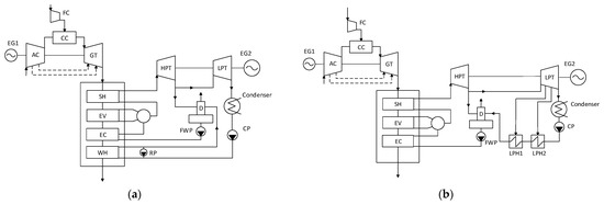
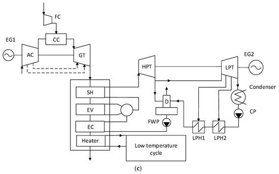
Figure 2.
Scheme of the studied combined cycle plants: (a) CCGT with CGH; (b) CCGT with regeneration; (c) trinary unit.
To study the effect of feed water temperature and the number of steam turbine regenerative bleeding off, the basic scheme was modified to the scheme shown in Figure 2b. It is a CCGT unit with a single-circuit waste heat boiler and two low pressure heaters (LPH). In this unit, the condensate is heated to the temperature at the inlet to the deaerator in the low-pressure regeneration system. Because of this, there is no gas condensate heater in the waste heat boiler. The condensate pump supplies water to the inlet of a series-connected group of low-pressure heaters, in each of which, the condensate temperature increases by the same amount. After heating in the regeneration system, the condensate enters the deaerator. Water heating in the LPH is carried out by steam bleeding from the LPT. Otherwise, the scheme and processes occurring in the unit coincide with the single-circuit CCGT.
The switch to trinary power plants should be carried out by modifying the thermal scheme of the CCGT unit with a single-circuit waste heat boiler and a developed regeneration system, shown in Figure 2b, by adding an additional cycle on a low-boiling substance (Figure 2c).
Since a trinary power plant contains an additional coolant circuit compared to a CCGT with a single-circuit waste heat boiler, it is reasonable to compare its efficiency with a CCGT with a double-circuit waste heat boiler (Figure 3). With the double-circuit CCGT scheme, a large amount of water is passed through the economizer to ensure a low temperature of exhaust gases, and less through the evaporation and superheating surfaces to obtain high initial steam parameters. The presence of two pressure circuits makes it possible to increase the efficiency of the boiler and the CCGT, and also leads to an increased recovery of the heat of the exhaust gases in the boiler.
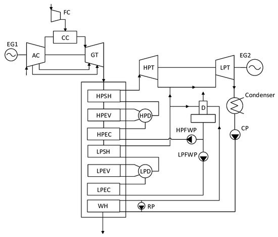
Figure 3.
Scheme of a double-circuit CCGT.
For all binary and trinary power plants, the model of the GTE-160 gas turbine plant, which is widespread in Russia, was considered, the main parameters of which are given in Table 1.

Table 1.
Characteristics of GTE-160.
2.2. Cycles on a Low-Boiling Coolant
As recovery cycles, power plants operating according to the following schemes were considered:
- Organic Rankine cycle (with and without regeneration);
- Kalina cycle;
- Rankine cycle on CO2;
- Brayton CO2 cycle (including compressor intercooling, turbine reheating, regenerator bypass).
The thermal scheme of the organic Rankine cycle can operate at two types of flow pressures: subcritical and supercritical. In Figure 4a, a diagram without regeneration is shown, and of which, the principle of operation is as follows. The working fluid expands in the turbine and then flow enters the condenser, in which the cooling and condensation process takes place. The resulting condensate is sent to the pump for compression and then moves to the heat source for heating. In addition, the paper considers cycles with regeneration (Figure 4b) used to reduce losses in the cold source. Unlike the simplest cycles, here, the turbine exhaust gas flow enters the regenerator, in which, due to its cooling, the flow at the pump outlet is heated.
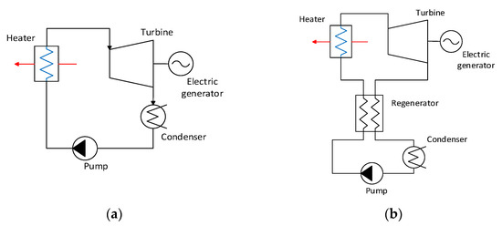
Figure 4.
Schemes of the organic Rankine cycle: (a) without regeneration; (b) with regeneration.
Another promising cycle for the recovery of low-grade heat is the Kalina cycle [17,18]. The thermal diagram of the simplest cycle with a regenerator is presented in Figure 5. A mixture of water and ammonia enters the pump inlet and, upon passing through the regenerator, is fed to the evaporator, where a part of the working fluid is converted into steam. Then, the mixture enters the separator, where the vapor fraction is separated from the liquid. Since the evaporation parameters of water are higher than those of ammonia, most of the ammonia is sent to the inlet to the turbine, where it operates and expands to the pressure in the condenser. The liquid stream, consisting mainly of water, leaves the separator and is directed to the regenerator, where it heats the mixture after the pump. After that, the flow is throttled to the pressure in the condenser and mixed with the flow at the outlet of the turbine and then enters the condenser.
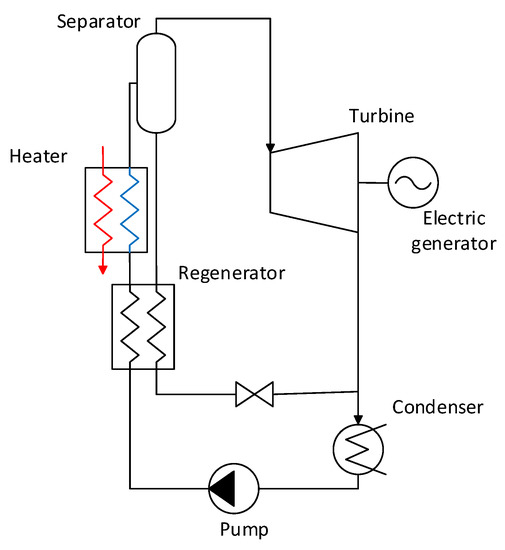
Figure 5.
Scheme of the Kalina cycle.
Since the critical parameters of carbon dioxide are 30.98 °C and 7.38 MPa, it can also be used as a heat coolant for recycling cycles. In this case, both closed Rankine cycles and closed Brayton cycles on supercritical carbon dioxide can be considered.
The scheme of the Rankine cycle on supercritical carbon dioxide is similar to that of the organic Rankine cycle (therefore, the scheme of the Rankine cycle on supercritical carbon dioxide is not shown separately in this paper). A closed Brayton cycle on carbon dioxide is shown in Figure 6a. In a cycle without regeneration, flow expands in the turbine, then flow enters the cooler in which it gives off heat to the cooling water. After cooling, the working fluid enters the compressor for compression, and then goes to the heat source for heating. In addition, the paper considers the cycle with regeneration used to reduce losses in the cold source. Here, the flow of exhaust gases from the turbine enters the regenerator, in which, due to its cooling, the flow at the exhaust from the compressor is heated. When calculating the plant with intercooling (Figure 6b), carbon dioxide after the first stage of the compressor enters the intercooler, where it is cooled to 32 °C. After that, the flow enters the second stage of the compressor and then goes to the regenerator. For the rest, this cycle coincides with the simple Brayton carbon dioxide cycle with a regenerator.
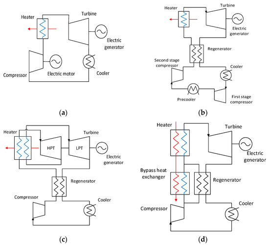
Figure 6.
Brayton closed circuit schemes: (a) basic Brayton cycle; (b) Brayton cycle with intercooling; (c) Brayton cycle with reheat; (d) Brayton cycle with regenerator bypass.
With re-superheating (Figure 6c), the difference from the basic cycle is that the carbon dioxide flow after the high-pressure part of the turbine enters the reheat heat exchanger, where it is heated again and enters the low-pressure section.
When using a bypass (Figure 6d), part of the flow after the compressor is fed to the regenerator, and part to the bypass heat exchanger, which, similar to the heater, heats the carbon dioxide flow with the help of exhaust gases. The temperature at the outlet of the heater was determined under the condition of an undercooling of 10 °C in the bypass heat exchanger. The medium flow rate at the compressor inlet was calculated to obtain an undercooling at the hot section of the heater equal to 20 °C, or a minimum undercooling of 10 °C inside the heater.
A wide variety of schemes solutions for the recovery of low-potential heat and the lack of energy-based recommendations for choosing their structure and parameters lead to the need of a thermodynamic analysis in order to identify the most efficient cycles.
3. Methodology of the Study
In this paper, the thermodynamic analysis methods for trinary power plants and a feasibility study of their parameters are necessary to study the flow scheme and design solutions. The analysis includes the choice of the most promising flow schemes for recovering the low-temperature exhaust gas heat; the thermodynamic analysis of switching from binary cycles to trinary ones, and the definition of the economically optimal design parameters for the main elements of the heat recovery cycle.
3.1. Method of Thermodynamic Analysis of Trinary Cycles
A thermodynamic analysis of the thermal schemes of combined cycle plants was carried out using the Aspen Plus software package [19]. To determine the thermophysical properties of working fluid, the NIST REFPROP database was used, which is characterized by high accuracy [20].
Figure 7 shows the visualization of the mathematical model of a CCGT with a single-circuit waste heat boiler, developed using the Aspen Plus software package. The model consists of several main blocks: a gas turbine plant with cooling, a steam turbine plant, a waste heat boiler represented by a set of successively installed heat exchangers, and a recovery plant. The developed model allows for a thermodynamic analysis to be conducted and for the optimization studies of flow schemes for binary and trinary power plants to be carried out.
Figure 7.
Mathematical model of a single-circuit steam–gas plant in the Aspen Plus software package.
The parameters of the gas turbine were selected in such a way as to obtain full compliance with the parameters of GTE-160 turbine [21] (Table 1). The calculation of flow rates for cooling was carried out according to the method described in [13]; for this, the compressor and the turbine were conditionally divided into stages, from which the refrigerant was taken, and into which, the refrigerant was supplied. The calculation of the combustion process in the combustion chamber was carried out under the condition of the reaction of the stoichiometric combustion of methane. The main parameters of gas turbine modeling are given in Table 2.
Table 2.
Initial data for the mathematical model of the gas turbine [13].
Processes of expansion and compression in turbomachines are calculated with constant isentropic efficiency according to the equations shown below.
The enthalpy at the outlet of the turbine was calculated by the formula:
where
- h1 and h2—the enthalpies at the turbine inlet and outlet, kJ/kg;
- h2′—a specific enthalpy of flow caused by isentropic pressure variation, kJ/kg;
- ηoi.T—isentropic turbine efficiency.
The enthalpy resulting from compression in a compressor or a pump was calculated using the formula:
where
- ηoi.C—isentropic compressor efficiency.
The waste heat boiler of the steam turbine unit consists of heat exchangers installed in series, in which the heat balance is calculated:
where
- h11 and h21—specific enthalpies of hot and cold flows at the heat exchanger inlet, kJ/kg;
- h12 and h22—specific enthalpies of hot and cold flows at the heat exchanger outlet, kJ/kg;
- G1 and G2—mass flow rates of hot and cold fluids, kg/s;
- Q—the heat exchanger thermal capacity, kW.
The initial data for modeling the thermal schemes of combined cycle plants are given in Table 3.
Table 3.
Main characteristics and parameters of a CCGT unit with a single-circuit waste heat boiler [13].
The net electric power of the gas turbine is calculated by the formula:
where
- —the electric power of the gas turbine, MW;
- —the electric power of the air compressor, MW;
- and —the mechanical efficiency factor and efficiency factor of the power generator.
The net electrical power of the steam turbine unit is calculated using the formula:
where
- —the gas turbine electric power, MW;
- —the electric power of the air compressor, MW;
- and —the mechanical efficiency factor and efficiency factor of the power generator.
The net electrical power of the CCGT is calculated using the formula:
The net electrical efficiency of the CCGT is calculated using the formula:
where
- B—the fuel flow rate, kg/s;
- LHV—the low heating value of natural gas, MJ/kg.
The electrical power of the trinary plant was determined as:
where —the net electric power of the recovery plant, MW.
For modeling the heat recovery cycle, the initial parameters have been taken, which are presented in Table 4.
Table 4.
Initial data for mathematical models of the waste heat recovery plant.
Thermodynamic analysis and optimization of schemes of recovery plants is carried out while taking into account certain conditions. As a result of the thermodynamic optimization of a combined cycle plant, the issue of choosing schemes for recovering the heat of exhaust gases is considered. The temperature, flow rate and composition of these gases after the economizer part (or after WH) do not depend on the choice of gas heat recovery parameters, and the minimum temperature limit at the outlet of the trinary plant is 80 °C. This limitation is due to the non-admission of vapor condensation in gases to prevent the corrosion of heat exchange surfaces. Taking into account the fact that in low-potential cycles, the temperature of the feed flow at the inlet to the waste heat recovery unit usually does not exceed 80 °C, it can be said that in all the cases under consideration, it is possible to cool the gas flow to the minimum possible temperature and transfer the maximum possible quantity of heat. This is a consequence of the fact that the thermal power supplied to the heat recovery cycle is a constant value, similar to the initial and final temperatures of the hot stream.
To ensure stable operation and small dimensions of the waste heat recovery unit, in which heat is transferred from the exhaust gases to the low-boiling coolant, it is necessary to provide a certain temperature difference in the heat exchanger. It should be taken into account that the pinch point can be located not only at the hot or cold end of the apparatus, but also at the vapor boiling point (or pseudo-phase transition in the case of a supercritical cycle). In order to satisfy the pinch requirements, the consumption of a low-boiling flow is controlled in this work. Additionally, thus, at a fixed level of heat input in the cycle, the output power in the recovery plant will be determined only by its energy efficiency.
3.2. Technique for Optimizing a Waste Power Plant
The selection of circuit solutions for power plants should be determined not only by the level of thermodynamic efficiency, but also by cost indicators, which leads to the need to use such objective functions that would include both the energy component and the economic one.
In recovery plants, in order to achieve maximum efficiency, a regeneration system can be used, in which, due to the introduction of additional heat exchange equipment, losses in the cold source of the cycle are reduced. The validity of the application of this circuit solution is determined as a result of the feasibility study. On the one hand, there is the question of achieving high energy efficiency, on the other hand, there is the question of limiting the total cost of power unit equipment. When referring to the heat exchange equipment of the regenerative system, the choice of the design of the regenerator, the type of heat exchange surfaces and the value of the total heat exchange area determine both the cost of the heat exchanger itself and the thermodynamic parameters of the cycle.
The final cost of the heat exchange equipment is determined, first of all, by weight and size characteristics, which directly depend on the required heat exchange area. According to the heat transfer equation A, the required heat transfer area can be determined from:
where
- Q—the heat exchanger thermal capacity, kW;
- U—heat exchange factor, W/m2 °C;
- dT—logarithmic mean temperature difference, °C.
The thermal power of the regenerator is determined by the mass flow rate of the fluids and the required level of their undercooling. In heat recovery cycles, the flow rate is most often determined by the parameters of the low-grade heat source and is an independent value for the regenerative system. Underheating is a value that depends only on the choice of the regenerator configuration, as well as the average temperature difference in the apparatus (assuming that the input parameters of the hot and cold fluids are almost independent of the operating mode of the regeneration system).
The heat transfer coefficient is determined by the configuration of the heat exchange surfaces and the mode of flow of the fluid (their flow rate). With an increase in the speed of movement of the flow, heat transfer intensifies, the thermal resistance to heat transfer decreases and, as a result, the required heat transfer area reduces. Thus, to reduce the cost of the regenerator, it would be possible to organize the maximum flow rate of the fluid in the channels (with a constant total mass flow rate by reducing the size of the channels or their number) with a high level of specific heat flow; however, the flow rate directly determines, among others, hydraulic losses. Increased pressure losses in the regenerator channels will lead to additional energy costs for pumping coolants, which will subsequently affect the energy efficiency of the entire cycle.
Thus, the final cost of the regenerator (determined through the metal consumption, which, in turn, is determined through the required heat exchange area) with a fixed configuration of heat exchange surfaces will depend on the degree of regeneration in the cycle specified when designing a new power unit (which depends only on the underheating of the working fluid in the regenerator) as well as on the permissible level of pressure losses (which depends on the flow rate of the fluid). At the same time, the degree of regeneration and pressure losses directly affect the efficiency of the recovery plant and, as a result, the power generation capacity:
where is the degree of regeneration in the recovery plant, defined as the ratio of the transferred heat in the regenerator to the maximum possible one :
where and are the mass enthalpies of the cold coolant at the outlet and inlet to the regenerator, kJ/kg; is the mass enthalpy of the cold coolant heated to the temperature of the hot coolant at the inlet to the regenerator, kJ/kg.
Thus, the degree of regeneration and the level of pressure losses in the regenerative system become the main characteristics that determine both the energy and economic efficiency of circuit solutions for the recovery plant and are selected during the design as the results of the feasibility study. This allows us to pass to the universal objective function, which will depend only on these two parameters and, thus, the problem of choosing their digital values is reduced to determining the extremum point of this function.
In this paper, for the technical and economic optimization of the regeneration system, the target function is the value that is the difference between the profit received from the generation of electricity in the heat recovery cycle and the costs of regeneration, defined as the cost of the heat exchanger divided by its service life. In order not to take into account the cost of the rest of the energy equipment of the recovery plant (pumps, turbines and other auxiliary equipment), it is possible to move from absolute cost values to incremental costs from a certain base level. This allows us to bring the target function to Formula (12). The use of such a target function will be valid if: when changes are made to the operation of the regeneration system, the cost of the rest of the designed equipment remains constant. Such simplification is acceptable if we take into account the fact that most of the cost of recovery plants is occupied by heat exchange equipment, since turbomachines operating on a low-boiling coolant usually have a high portability, in contrast to heat exchange equipment [22]. For the base level, indicators of a recovery plant without a regeneration system are used, which have a fixed profit from the supplied power and no costs for the regenerator.
where
- —the change in the target function USD/year;
- —change in the net power of the recovery plant, MW;
- —cost of electrical power supply, USD/MWh;
- h—operating hours per year, hours.
- —change in the cost of the regenerator, USD;
- t—the service life of the regenerator, years.
Thus, when conducting a feasibility study of the regenerative system using this target function, it is expected to obtain such a set of operating and design parameters of the regenerator, which will provide for the maximum difference between the profit from electricity generation and the cost of heat exchange equipment. The assumption with regard to the presence of an extremum of the target function on the degree of regeneration has the following grounds: when (there is no regeneration), the value of the target function will correspond to the value of the function for the cycle without regeneration, and its increment will be equal to zero; with an increase in the degree of regeneration, the cycle efficiency will increase and the power and profit from power generation will increase, while the cost of the regenerator will also increase; and in the limiting case at , the cost of the regenerator will tend to infinity (due to the near-zero undercooling of the fluid at the outlet of the heat exchanger), while the efficiency will have some finite value. When studying the effect of pressure losses, an optimum can also be achieved: the minimum values of hydraulic resistance will be observed in the case of a low flow speed of the fluid, which will lead to a low value of the heat transfer factors and, as a result, to a very large required heat exchange area and the cost of the regenerator, while the efficiency will have some final value corresponding to the calculation of the heat recovery cycle without taking into account pressure losses; and at infinitely high flow rates of the fluid, there will be a low thermal resistance to heat transfer, which will lead to high specific heat flows and, as a result, a low cost of the regenerator, while the efficiency will be minimal due to large energy losses for pumping the fluid.
To determine the optimal values of the operating parameters of the regenerator, multi-series thermodynamic calculations of the heat recovery cycle were carried out in the work to determine the nature of the change in the output power with a change in the degree of regeneration and pressure losses (according to the method described in Section 3.1), and the cost of the regenerative system was estimated based on these parameters.
The cost of the regenerator in this work was estimated as the sum of the costs of materials for the manufacture of the main structural elements (heat exchange surfaces, housing, additional elements) and the costs of manufacturing operations (soldering, cutting). In the heat exchanger, the main component of the cost is the cost of metal for the manufacture of heat exchange surfaces (pipes, plates), which make up the largest part of the total cost of the apparatus [23]. The heat exchange surface costs are determined by the required heat exchange area , which is directly determined, as noted earlier, by the performance of the regenerative system.
The calculation of the heat exchange surface area of the regenerator was carried out according to the method described in [24], the key formula is (9). To determine the heat transfer parameters in the channels of the plate-tubular apparatus, the correlation equations for the Nusselt number and the hydraulic loss coefficient presented in [25] were used.
AISI 316 stainless steel, which is often used in the manufacture of heat exchangers operating at low temperatures, was considered as the material for the manufacture of heat exchange surfaces. The main constants used in the course of the feasibility study are given in Table 5.
Table 5.
Basic constants for calculating the cost of the regenerator.
4. Thermodynamic Analysis
The results of thermodynamic analysis showed that the development of regeneration in the steam turbine part leads to an increase in the temperature of the feed water and, as a consequence, the temperature of exhaust gases. This causes a drop in the total efficiency of the entire combined cycle unit due to the less deep heat utilization of the exhaust gases. The graphs of dependence of CCGT efficiency and exhaust gas temperature on feed water temperature for a single-circuit plant without regeneration, with regeneration and a double-circuit plant are shown in Figure 8. The feed water temperature was controlled by changing the pressure in the deaerator (the standard range of pressures for deaerators is 0.12, 0.3 and 0.7 MPa). An increase in the feed water temperature by 60 °C leads to a decrease in the cycle efficiency by 2.3% in a trinary cycle with regeneration and by 0.6% when using a double-circuit CCGT (Figure 8a). On the other hand, an increase in the feed water temperature by 60 °C leads to an increase in the exhaust gas temperature by 30 °C in a trinary cycle with regeneration and in a double-circuit cycle (Figure 8b). Adding a regeneration system to a single-circuit plant leads to a drop in overall efficiency due to increased losses with the heat of exhaust gases. The efficiency of a double-circuit plant is, on average, 1.1–1.7% higher than that of a single-circuit plant, primarily due to a deeper recovery of the exhaust gas heat.
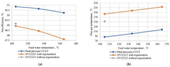
Figure 8.
Graphs of CCGT net efficiency dependence and exhaust gas temperature on feed water temperature: (a) CCGT net efficiency; (b) exhaust gas temperature.
To recover the heat of exhaust gases, various cycles on low-boiling coolants were considered in the work. A comparison of their energy efficiency is given in Figure 9. When adding a heat recovery cycle to the CCGT unit with the exhaust gas temperature of 183.6 °C (with their further cooling to 80 °C in the cycle), the most effective is the organic Rankine cycle with R236ea coolant. The prospect of using this coolant was substantiated in the work [13]. The net efficiency of the ORC reaches 15.2%, which is significantly higher than the closest efficient cycle, the Brayton CO2 cycle with a regenerator bypass. The addition of a regenerator to this cycle made it possible to increase its efficiency to 18.9%, which indicates that at a temperature in the hot source of about 150–200 °C, the organic Rankine cycle with regeneration is the most promising due to its high efficiency and relatively small amount of main equipment. The increased thermal efficiency of this cycle is explained by the phase curve shape: when heating freon in a waste heat boiler, we can observe the highest average integral temperature of heat supplied to the cycle (including through heat recovery), taking into account the restrictions on the minimum temperature difference. Brayton cycles on carbon dioxide with a regenerator and compressor intercooling, reheated in an expander with a regenerator bypass have a relatively lower efficiency, and the number of equipment (primarily heat exchangers) exceeds the number of equipment in the ORC. The Kalina cycles also have relatively more equipment, and their efficiency in this temperature range does not reach the efficiency of the Rankine cycle.
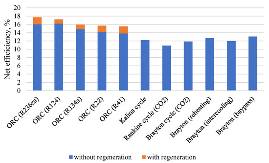
Figure 9.
Efficiency of various heat recovery cycles for a trinary power plant.
Thus, the most effective circuit solution will be the use of an organic Rankine cycle on R236ea freon as a recovery plant for a CCGT operating according to a trinary cycle and having a developed regeneration in the steam–water part. The final scheme and parameters of the trinary power plant on the T-S diagram are shown in Figure 10.
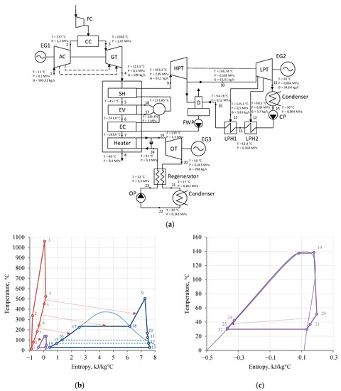
Figure 10.
Trinary plant diagram and its T-S diagram: (a) results of optimizing the parameters of the thermal scheme of a trinary power plant; (b) T-S diagram of the trinary plant (red line—gas turbine unit, blue line—steam turbine unit, purple line—ORC, dashed lines—heat recovery); (c) T-S diagram of the organic Rankine cycle.
Due to the fact that the low-potential part of the heat of the exhaust gases is not used in the steam–water cycle, as in the traditional combined cycle plant, but is transferred to a more energy-efficient heat recovery cycle on a low-boiling coolant, the total generation of electrical energy increases. Additionally, this effect is affected by an increase in the efficiency of the steam–water circuit due to the development of regeneration. This allows trinary power units to compete not only with single-circuit CCGTs, but also with double-circuit units—the absolute increase in efficiency compared to a single-circuit unit is more than 2.25%, and when compared with a double-circuit unit, it is more than 0.55% (Figure 11). This effect is due to transferring part of the low-temperature heat of the exhaust gases from the steam–water cycle to the freon cycle where the maximum energy efficiency is achieved due to a higher average of integrated heat supply temperature.

Figure 11.
Comparison of the efficiency of combined cycle plants.
Such results are valid for the same cooling depth of exhaust gases in these power units of up to 80 °C. However, the production of waste heat boilers with condensing heat exchangers is promising, with the cooling depth of the exhaust gases reaching 40–50 °C, for more power generation [26]. When operating under such conditions, the comparative energy efficiency of trinary plants will be even higher than that of typical binary ones, which emphasizes the promise of these circuit solutions.
5. Technical and Economic Optimization of a Waste Heat Recovery Unit
When implementing these circuit solutions, not only the issue of energy efficiency, but also cost indicators come into focus. The issue of the design performance of equipment for low-boiling coolant cycles remains poorly studied today, and also, due to their low prevalence in the energy industry, information on the economic efficiency indicators of these plants is not enough to select specific circuit solutions. In turn, equipment for operating on a steam–water coolant is widespread and there are many works with recommendations on the selection of circuit and design parameters for steam turbine and combined cycle power units. Therefore, in order to select circuit solutions for exhaust gas heat recovery in trinary cycles, general recommendations are needed that would take into account both energy and economic indicators of the operation of recovery plants.
5.1. Influence of Regeneration on Heat Recovery Efficiency
The Rankine cycle with R236ea organic coolant at the given initial parameters turned out to be the most energy-efficient way of recovering the heat of exhaust gases. The reasons comprise various factors: starting with a higher average integral temperature of heat supply due to the form of the phase transition, and ending with a high degree of regeneration in the cycle and, as a result, a relatively low level of losses in the cold source.
The regenerator in the ORC is a heat exchanger that serves to transfer the heat that has worked out in the Freon turbine of the working environment to the liquid after the pump. From a thermodynamic point of view, the efficiency of the regenerative system can be characterized by the degree of regeneration φ, which is the ratio of the power transferred in the heat exchanger to the maximum possible at zero undercooling, as well as the level of pressure losses in the hot and cold channels. To date, there are no generally accepted recommendations on the selection of allowable losses for pumping fluid and on the selection of the degree of regeneration in the organic Rankine cycle—these parameters affect both the efficiency and the total cost of the system.
The graphs of the dependence of the net efficiency of the organic Rankine cycle on Freon R236ea on the degree of regeneration in the cycle and on pressure losses in the regenerator are shown in Figure 12. When calculating a cycle with pressure losses, it was assumed in the first approximation that the losses in the hot channel and in the cold one are equal. This assumption is due to the lack of information on the design of the channels at this stage, but in the future, this assumption will be excluded (Section 5.3). From the point of view of the influence on thermodynamics, this assumption is acceptable due to the fact that the energy costs for pumping the coolant are directly proportional to the pressure losses multiplied by the volumetric flow rate, and taking into account the difference in volumetric flow rates for hot and cold fluid by more than 2 degrees (Section 5.2), we can conclude that the efficiency is more affected by losses in the hot channel.
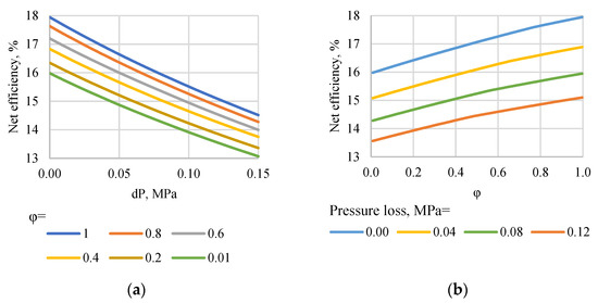
Figure 12.
The dependence of the net efficiency of the ORC on: (a) pressure losses in the regenerator; (b) the degree of regeneration.
It can be seen from the graphs that both the degree of regeneration and pressure loss linearly affect the final value of the efficiency of the organic cycle. Therefore, with an increase in pressure loss in the regenerator by about 10 kPa, the efficiency of the organic cycle decreases by 0.25%, and with an increase in the degree of regeneration by 10%, the efficiency of the cycle increases by an average of 0.2%. This is due to the need to compensate for pressure losses because of additional energy losses for pump operation or a higher pressure downstream of the turbine. The most optimal solution is the second option, since its stable operation requires maintaining a preset pressure level in the condenser.
It should also be taken into account that changes in the regenerative system affect, among others, the level of the optimal initial pressure in the cycle (Figure 13). With a decrease in the degree of regeneration, the optimal pressure decreases, while with an increase in pressure losses, the value increases. This should be taken into account when studying the influence of the characteristics of the regenerator on the energy performance of the cycle and when optimizing the initial pressure at each stage.

Figure 13.
Variation of the optimal initial pressure depending on the degree of regeneration and pressure losses (dashed lines—optimal pressure).
The degree of regeneration in the cycle can vary from 0 to 1, which corresponds to the case of the absence of a heat exchanger and the case of the most efficient heat exchanger with a zero undercooling of coolants. The first case is schematically equivalent to the organic Rankine cycle without regeneration, and the net efficiency values of these cycles will be equal accordingly. The second one can be provided with an infinitely large heat exchange area. At the same time, it should be taken into account that pressure losses in the additional heat exchanger can reduce the efficiency of the cycle, and at a certain value, the efficiency can become even lower than in a cycle without regeneration. In this case, the installation of a regenerator does not make sense.
The graph of the dependence of the net efficiency of the organic Rankine cycle on R236ea on the degree of regeneration and pressure loss in the regenerator at optimal initial pressures is shown in Figure 14. The upper blue line corresponds to a cycle with a regenerator without pressure loss, and the red line corresponds to a cycle without a regenerator. These two cases define the area in which the installation of the regenerator is thermodynamically justified. It can be seen from the graph that at pressure losses of 80 kPa or more, the efficiency of the cycle at any, even at the highest degree of regeneration, becomes lower than the efficiency of the cycle without regeneration. Thus, the economically justified characteristics of the regenerative system can be determined in a rather limited range.
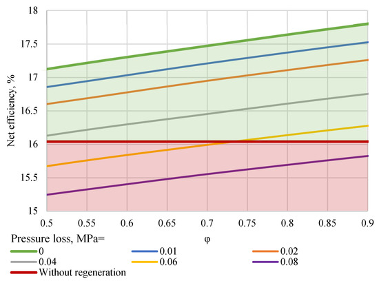
Figure 14.
Graph of dependence of the net efficiency of ORC on the degree of regeneration and pressure loss at optimal parameters in the cycle.
5.2. Selection of Design Solutions for Regeneration in the Heat Recovery Cycle
One of the main issues that determine the technical and economic efficiency of the regeneration system in a recovery plant is the choice of design solutions for heat exchange equipment. A wide variety of design options for heat exchangers and the lack of reasonable recommendations for the choice of the shape and geometry of heat exchange surfaces necessitate an analysis of the trends for the use of certain types of a heat exchanger design for cycles on a low-boiling coolant. This can largely determine not only the energy efficiency of the recovery plant, but also the weight and size indicators of the regeneration system and, as a result, its cost.
The main types of heat exchangers used in the organic Rankine cycle are shell and tube, plate and plate-and-tube heat exchangers. A shell-and-tube heat exchanger is a plurality of tubes enclosed in a casing, where heat exchange is carried out through the surface of these tubes. Most often, the opposite direction of the movement of coolants is provided, which contributes to the most efficient heat transfer. Plate heat exchangers consist of several corrugated metal plates in contact. Each plate has four holes, which are inlets and outlets. The plates are fastened together in a frame, and for operation at high pressures (up to 5 MPa), the plates are welded together. Plate-and-tube heat exchangers are widely used in cases where one coolant is a liquid, and the other is air or another gas. They are highly compact heat exchangers, due to the high values of the heat exchange area, which they have due to intensive finning [27].
The peculiarity of the operating mode of the organic Rankine cycle regenerator is determined, first of all, by the significantly different volumetric flow rates of the heated and heating fluid (Figure 15). This is due to the different aggregate state of the coolants (steam after the Freon turbine heats the condensate after the pump) and the level of Freon operating pressures (fluids’ pressures are about 0.24 MPa and more than 4 MPa). This leads to the need to choose design solutions that would allow, at acceptable flow rates of the fluids and low-pressure losses in both channels, the necessary specific heat flows in the heat exchanger to be obtained with its small weight and size indicators.
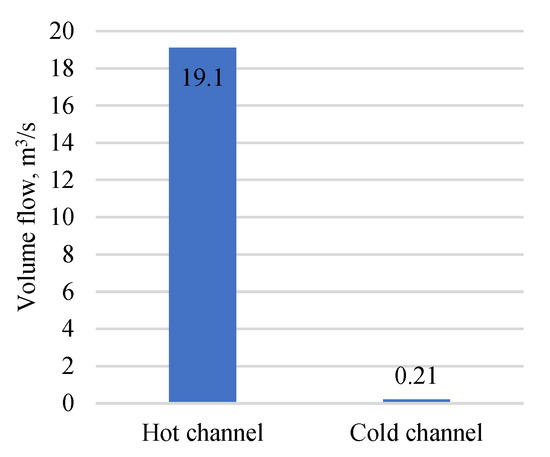
Figure 15.
Volumetric flow rates of hot and cold fluids in the ORC regenerator.
By calculation, the main weight and size characteristics of the regenerator were determined when choosing a different design of the heat exchanger: welded plate, shell-and-tube and plate finned tube heat exchanger. Due to the fact that at the same flow rates in a plate-tubular apparatus, it is possible to provide a relatively high speed, both in hot and cold fluids, while limiting pressure losses of 100 kPa, it is possible to achieve a low thermal resistance to heat transfer in cold and hot channels (Figure 16a). This makes it possible to reduce the required heat exchange area and, as a result, the weight and dimensions (Figure 16b). In turn, in a plate heat exchanger, the speed of the movement of both coolants is determined by the number of channels along the cold and hot streams (depending directly on the number of plates). Therefore, at high pressure losses in the hot channel, a low flow velocity and a high resistance to heat transfer will be observed in the cold channel, even despite the use of the complex corrugation of the plates. The shell-and-tube heat exchanger, due to the low compactness according to the design, will have the largest dimensions which limits its use in waste heat recovery plants. The plate-tubular heat exchanger has a high compactness due to intensive plate finning (Figure 16c). This contributes to the achievement of the minimum dimensions of the regenerator, in connection with which this type of design was chosen for further feasibility study.
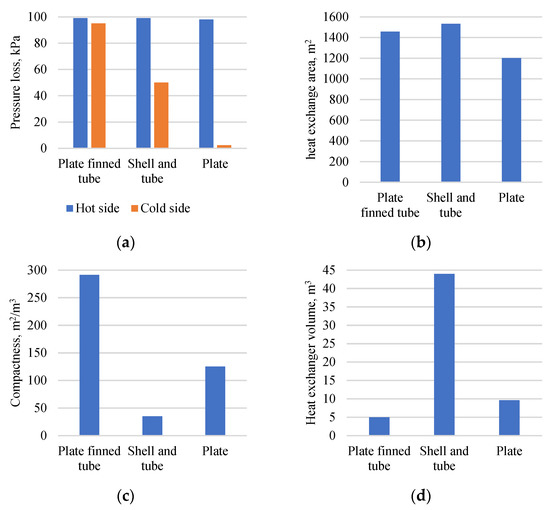
Figure 16.
Characteristics of the regenerator when choosing different types of heat exchanger design: (a) pressure losses; (b) heat exchange area; (c) compactness of the heat exchanger; (d) heat exchanger volume.
5.3. Technical and Economic Optimization of the Regenerator Design
As it was found, from the thermodynamic point of view, the introduction of the regenerator can be justified in the range of pressure losses up to 80 kPa along the hot channel, and depending on the level of losses, the maximum allowable (in terms of maintaining an acceptable level of efficiency) degree of regeneration varies.
The diagram of the dependence of the plate-and-tube regenerator cost on the degree of regeneration in the cycle and the permissible level of pressure loss in the hot channel (with the initial pressure optimal for each point) is shown in Figure 17. It can be seen from the graphs that with the regeneration degree of 0.45, an increase in losses in the regenerator has little effect on the change in the cost of the heat exchanger. The nature of the dependence is nonlinear, and with lower pressure losses, the cost of the heat exchanger changes significantly, whereas with an increase in these losses, the change in the cost of the regenerator decreases. For example, with the regeneration degree of 0.85, an increase in losses from 10 to 20 kPa leads to a decrease in cost by an average of 13%, while an increase in pressure losses from 40 to 60 kPa leads to a decrease in the cost of a regenerator by an average of 7%. Increasing the degree of regeneration in the cycle also affects the cost of heat exchange equipment. From Figure 17b, it can be seen that with an increase in the degree of regeneration from 0.5 to 0.6, the cost of the regenerator increases by about 1.5 times, while an increase in regeneration from 0.8 to 0.9 results in an increase in the cost of equipment by about 2.5 times. With low allowable pressure losses, the high regenerator cost is due to the need to use a large heat exchange area because of low medium flow rates and, as a result, a low heat transfer in the heat exchanger. In turn, a high recovery level causes a low temperature difference in the regenerator, which requires to increase the heat exchange area.
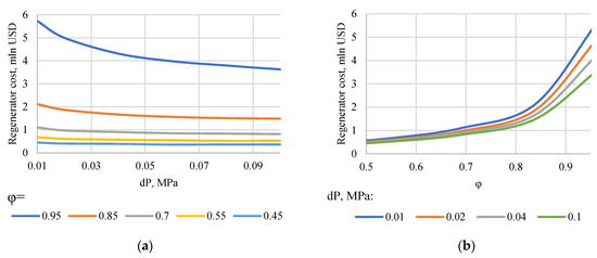
Figure 17.
Graph of the dependence of the cost of a plate-and-tube regenerator: (a) pressure losses in the regenerator; (b) the degree of regeneration in the cycle.
Combining data on energy efficiency and the cost of the regenerator, dependences for the target function on the degree of regeneration and pressure losses were obtained (Figure 18). The nature of the change in the target function indicates that an increase in pressure losses in the considered range (from 10 to 80 kPa) leads to a drop in the average values of the target function, and the maximum values are reached at dP = 10 kPa. At the same time, with an increase in losses by 20 kPa, it leads to a reduction in the value of the target function by an average of 0.09 million USD/year, and at some values of φ, the effect of introducing the regenerator becomes negative. Hence, at the cost of electricity = 0.04 USD/kWh (a value typical for the electricity market in Russia), with a degree of regeneration of less than 50% and more than 90%, the target function has negative values at losses of 40 kPa, and the installation of a regenerative system does not make sense, while at losses of 60 kPa, this effect is observed at any φ. The optimal value of the degree of regeneration in the cases under consideration, for almost any loss, is the value φ = 80%—with this value, the maximum target function is achieved. At a higher cost of electricity supply, the effect of the introduction of the regenerative system is more pronounced and the minimum allowable level of pressure losses, at which the target function has positive values, becomes higher. The presence of an optimum can be explained as follows: with a low recovery, the ORC efficiency is relatively low, whereas with a high recovery, the regenerator cost exceeds the cost-effective threshold.
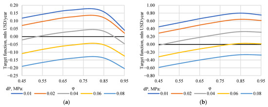
Figure 18.
Graph of the dependence of the target function on the degree of regeneration in the heat recovery cycle and on the level of permissible pressure losses at different costs of supplied electricity: (a) Ce = 0.04 USD/kWh; (b) Ce = 0.14 USD/kWh.
The degree of regeneration in the cycle equal to 80% (corresponds to the minimum temperature difference in the heat exchanger 6 °C) is economically justified. This conclusion correlates with works in which the value of subcooling in heat exchangers of 5–10 °C is used for thermodynamic analysis.
Therefore, the choice of the most optimal flow scheme solutions for combined cycle power plants, including for trinary power plants, is determined not only by energy efficiency, but also by external factors, such as the choice of design solutions for the recovery system, the cost of electricity supply, and others. In countries with a relatively low cost of electricity (for example, in Russia), the effect of introducing a regenerator into the cycle would be less pronounced, in contrast to countries with a higher cost of energy. The transition from binary-cycle CCGTs to trinary power plants may be appropriate within a certain range of prices for the supplied electricity. Figure 19 shows a graph of the payback period for a trinary power plant depending on the cost of electricity supply. Thus, if the cost of energy supply is 0.024 USD/kWh or more, the project payback period is shorter than the equipment service life (the estimated service life is 20 years).
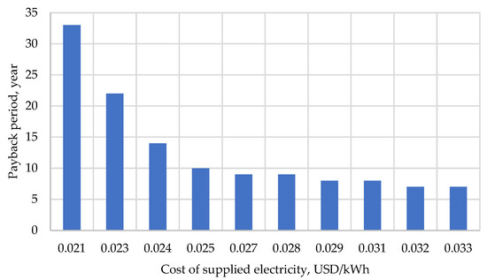
Figure 19.
Graph of the dependence of the payback period of a trinary power plant on the cost of electricity supply.
Therefore, the prospects for transition from binary to trinary plants are largely determined by external factors, primarily by market prices for the electricity supply and the cost of quotas for carbon dioxide emissions. Due to their higher energy efficiency and, as a result, environmental friendliness, trinary power plants can compete with traditional binary CCGTs.
6. Conclusions
In this paper, we have suggested new recommendations for choosing flow scheme and design parameters for trinary power plants, which provide the optimal energy and economic indicators:
- To conduct optimization studies, a method was developed for conducting thermodynamic studies and optimizing the thermal schemes of trinary power plants, as well as conducting a feasibility study for choosing the scheme parameters of the regenerative system of the waste heat recovery unit. Using the proposed method, we have developed recommendations for choosing a set of flow scheme parameters for a trinary power plant.
- It was found in the work that deploying a recovery system in a combined cycle steam turbine plant provides an increase in the temperature of the feed water and, as a result, an increase in the temperature of the flue gases from the waste heat boiler. This makes the flow scheme for adding an extra cycle using a low-boiling coolant promising, which allows the efficient use of the heat of flue gases to generate additional electrical energy.
- The use of the organic Rankine cycle with freon R236ea as a coolant for the recovery of the heat of exhaust gases makes it possible to achieve the maximum efficiency of the trinary power plant. The net cycle efficiency of the trinary plant with a GTE-160 gas turbine reaches 51.3%, which is 0.4% higher than the efficiency of modern double-circuit CCGTs and 2.1% higher than the efficiency of modern double-circuit CCGTs. This indicates that the use of circuits of trinary power plants can help increase the efficiency of electricity generation and, as a result, reduce emissions of harmful substances into the atmosphere.
- The add-on in the organic Rankine cycle of the regenerative system allows an increase in efficiency by more than 1.6%, while the final level of efficiency will be determined by the selection of the operating degree of regeneration in the cycle; its increase by 10% leads to an increase in efficiency by an average of 0.2%. At the same time, the introduction of additional equipment will lead to additional energy costs for pumping coolants. It has been established that an increase in pressure losses in the regenerator by 10 kPa leads to a decrease in the efficiency of the ORC by an average of 0.25%.
- The choice of circuit parameters of the recovery plant directly determines, in addition to thermodynamic efficiency, the cost indicators of the operation of the power unit. It has been established that a change in the degree of regeneration and the level of permissible pressure losses in the regenerator directly and nonlinearly affects its cost: an increase in the degree of regeneration from 0.5 to 0.6 leads to an increase in the cost of the heat exchanger by 1.5 times, and from 0.8 to 0.9 by more than 2.5 times. Increasing the allowable pressure loss from 10 to 20 kPa leads to a cost reduction by an average of 13%, and an increase from 40 to 60 kPa by 7%.
- The selection of optimal parameters for the operation of the regeneration system is determined by both thermodynamic and economic indicators. When using the difference between the change in profit from electricity generation and the cost of the regenerative system, divided by years of service, as an optimum criterion, the optimal value for the degree of regeneration in the organic Rankine cycle used in the trinary power plant is 80%. The pressure loss level of 10 kPa also provides the maximum value of the target function.
Therefore, the prospects for transition from binary to trinary plants are largely determined by external factors, primarily by market prices for the electricity supply and the cost of quotas for carbon dioxide emissions. Due to their higher energy efficiency and, as a result, environmental friendliness, trinary power plants can compete with traditional binary-circuit CCGTs. With a cost of energy supply of 0.024 USD/kWh or higher, the operation of trinary power plants can be economically feasible.
Author Contributions
Conceptualization, V.K.; methodology, I.K.; software, I.K.; validation, I.K., I.M. and T.X.; formal analysis, C.X.; investigation, I.M.; resources, T.X.; data curation, C.X.; writing—original draft preparation, I.M.; writing—review and editing, C.X.; visualization, T.X.; supervision, V.K.; project administration, V.K.; funding acquisition, V.K. All authors have read and agreed to the published version of the manuscript.
Funding
This study was conducted by the National Research University “Moscow Power Engineering Institute” and was supported by the Russian Science Foundation under Agreement No. 21-79-00262 dated by 27 July 2021.
Conflicts of Interest
The authors declare no conflict of interest.
References
- IEA. Global Energy Review 2019; IEA: Paris, France, 2020. [Google Scholar]
- Singh, S. Energy Crisis and Climate Change: Global Concerns and Their Solutions. In Energy: Crises, Challenges and Solutions; Wiley: Hoboken, NJ, USA, 2021; pp. 1–17. [Google Scholar]
- Okajima, Y.; Torigoe, T.; Mega, M.; Kuwabara, M.; Okaya, N. Development of Advanced TBC for 1650 °C Class Gas Turbine. In Proceedings of the ITSC2021, Virtual Event, 24–28 May 2021; ASM International: Detroit, MI, USA, 2021; pp. 695–699. [Google Scholar]
- Morimoto, K.; Matsumura, Y.; Iijima, T.; Wakazono, S.; Kataoka, M.; Yuri, M. Validation Results of 1650°C Class JAC Gas Turbine at T-Point 2 Demonstration Plant. Mitsubishi Heavy Ind. Tech. Rev. 2021, 58, 12. [Google Scholar]
- Morimoto, K.; Matsumura, Y.; Suzuki, K.; Wakazono, S.; Kataoka, M.; Yuri, M. Operation Status of 1650 °C Class M501JAC Gas Turbine at T-Point 2 Power Plant Demonstration Facility. Mitsubishi Heavy Ind. Tech. Rev. 2021, 58, 10. [Google Scholar]
- Ol’khovskii, G.G. The Most Powerful Power-Generating GTUs (a Review). Therm. Eng. 2021, 68, 490–495. [Google Scholar] [CrossRef]
- Rogalev, A.; Rogalev, N.; Kindra, V.; Zlyvko, O.; Vegera, A. A Study of Low-Potential Heat Utilization Methods for Oxy-Fuel Combustion Power Cycles. Energies 2021, 14, 3364. [Google Scholar] [CrossRef]
- Rogalev, N.; Kindra, V.; Komarov, I.; Osipov, S.; Zlyvko, O.; Lvov, D. Comparative Analysis of Low-Grade Heat Utilization Methods for Thermal Power Plants with Back-Pressure Steam Turbines. Energies 2021, 14, 8519. [Google Scholar] [CrossRef]
- Bălănescu, D.-T.; Homutescu, V.-M. Performance Analysis of a Gas Turbine Combined Cycle Power Plant with Waste Heat Recovery in Organic Rankine Cycle. Procedia Manuf. 2019, 32, 520–528. [Google Scholar] [CrossRef]
- Galashov, N.; Tsibulskiy, S.; Serova, T. Analysis of the Properties of Working Substances for the Organic Rankine Cycle Based Database “REFPROP”. EPJ Web Conf. 2016, 110, 01068. [Google Scholar] [CrossRef]
- Galashov, N.N.; Tsibulskiy, S.A. Parametric Analysis of the Diagram of the Combined-Cycle Gas Turbine with a Combination of Three Cycles for Improving Efficiency When Operating in Northern Gas Producing Areas. Bull. Tomsk Polytech. Univ. Geo Assets Eng. 2019, 330, 44–50. [Google Scholar]
- Milman, O.; Shifrin, B.; Perov, V.; Lukin, V.; Chebanuk, S. The Working Medium for the Megawatt Class Utilization Heat and Power Complex Based on Organic Rankine Cycle. J. Phys. Conf. Ser. 2018, 1105, 012094. [Google Scholar] [CrossRef]
- Kindra, V.; Rogalev, N.; Osipov, S.; Zlyvko, O.; Naumov, V. Research and Development of Trinary Power Cycles. Inventions 2022, 7, 56. [Google Scholar] [CrossRef]
- Ancona, M.A.; Bianchi, M.; Branchini, L.; De Pascale, A.; Melino, F.; Peretto, A.; Torricelli, N. Systematic Comparison of ORC and S-CO2 Combined Heat and Power Plants for Energy Harvesting in Industrial Gas Turbines. Energies 2021, 14, 3402. [Google Scholar] [CrossRef]
- Matuszewska, D.; Olczak, P. Evaluation of Using Gas Turbine to Increase Efficiency of the Organic Rankine Cycle (ORC). Energies 2020, 13, 1499. [Google Scholar] [CrossRef]
- Carcasci, C.; Cheli, L.; Lubello, P.; Winchler, L. Off-Design Performances of an Organic Rankine Cycle for Waste Heat Recovery from Gas Turbines. Energies 2020, 13, 1105. [Google Scholar] [CrossRef]
- Zhang, X.; He, M.; Zhang, Y. A Review of Research on the Kalina Cycle. Renew. Sustain. Energy Rev. 2012, 16, 5309–5318. [Google Scholar] [CrossRef]
- Kalina, A.I. Combined Cycle and Waste Heat Recovery Power Systems Based on a Novel Thermodynamic Energy Cycle Utilizing Low-Temperature Heat for Power Generation. In Proceedings of the 1983 Joint Power Generation Conference: GT Papers, Indianapolis, IN, USA, 25–29 September 1983; American Society of Mechanical Engineers: Indianapolis, IN, USA, 1983; p. V001T02A003. [Google Scholar]
- Aspen Technology, Inc. Aspen Plus. Available online: https://www.aspentech.com/en/products/engineering/aspen-plus (accessed on 19 July 2021).
- Lemmon, E.W.; Huber, M.L.; McLinden, M.O. NIST Standard Reference Database 23. In Reference Fluid Thermodynamic and Transport Properties (REFPROP); NIST: Gaithersburg, MD, USA, 2010; Volume 9. [Google Scholar]
- Trukhniy, A. Combined-Cycle Plant of Power Stations; MPEI: Moscow, Russia, 2013. [Google Scholar]
- Macchi, E.; Astolfi, M. Axial Flow Turbines for Organic Rankine Cycle Applications. In Organic Rankine Cycle (ORC) Power Systems; Elsevier: Amsterdam, The Netherlands, 2017; pp. 299–319. ISBN 978-0-08-100510-1. [Google Scholar]
- Woods, D.R.; Anderson, S.J.; Norman, S.L. Evaluation of Capital Cost Data: Heat Exchangers. Can. J. Chem. Eng. 1976, 54, 469–488. [Google Scholar] [CrossRef]
- Thulukkanam, K. Heat Exchanger Design Handbook; CRC Press: Boca Raton, FL, USA, 2013. [Google Scholar]
- Kim, N.; Youn, B.; Webb, R. Air-Side Heat Transfer and Friction Correlations for Plain Fin-and-Tube Heat Exchangers with Staggered Tube Arrangements. J. Heat Transfer. 1999, 121, 662–667. [Google Scholar] [CrossRef]
- Zhang, C.; Liu, C.; Wang, S.; Xu, X.; Li, Q. Thermo-Economic Comparison of Subcritical Organic Rankine Cycle Based on Different Heat Exchanger Configurations. Energy 2017, 123, 728–741. [Google Scholar] [CrossRef]
- Wang, C.-C.; Hsieh, Y.; Lin, Y. Performance of Plate Finned Tube Heat Exchangers under Dehumidifying Conditions. J. Heat Transfer. 1997, 119, 109–117. [Google Scholar] [CrossRef]
Disclaimer/Publisher’s Note: The statements, opinions and data contained in all publications are solely those of the individual author(s) and contributor(s) and not of MDPI and/or the editor(s). MDPI and/or the editor(s) disclaim responsibility for any injury to people or property resulting from any ideas, methods, instructions or products referred to in the content. |
© 2023 by the authors. Licensee MDPI, Basel, Switzerland. This article is an open access article distributed under the terms and conditions of the Creative Commons Attribution (CC BY) license (https://creativecommons.org/licenses/by/4.0/).