Article

Carnot Battery Based on Brayton Supercritical CO2 Thermal Machines Using Concentrated Solar Thermal Energy as a Low-Temperature Source

by
José Ignacio Linares
1,*,
Arturo Martín-Colino
1,
Eva Arenas
1,2,
María José Montes
3,
Alexis Cantizano
1,2 and
José Rubén Pérez-Domínguez
1
1
Rafael Mariño Chair on New Energy Technologies, Comillas Pontifical University, Alberto Aguilera 15, 28015 Madrid, Spain
2
Institute for Research in Technology, Comillas Pontifical University, Santa Cruz de Marcenado 26, 28015 Madrid, Spain
3
Department of Energy Engineering, Universidad Nacional de Educación a Distancia (UNED), Juan del Rosal 12, 28040 Madrid, Spain
*
Author to whom correspondence should be addressed.
Energies 2023, 16(9), 3871; https://doi.org/10.3390/en16093871
Submission received: 27 February 2023 / Revised: 29 April 2023 / Accepted: 1 May 2023 / Published: 2 May 2023
(This article belongs to the Topic Heat Exchanger Design and Heat Pump Efficiency)

Abstract

:
Carnot batteries store surplus power as heat. They consist of a heat pump, which upgrades a low-temperature thermal energy storage, a high-temperature storage system for the upgraded thermal energy, and a heat engine that converts the stored high-temperature thermal energy into power. A Carnot battery is proposed based on supercritical CO2 Brayton thermodynamic cycles. The low-temperature storage is a two-tank molten salt system at 380 °C/290 °C fed by a field of parabolic trough collectors. The high-temperature storage consists of another two-tank molten salt system at 589 °C/405 °C. Printed circuit heat exchangers would be required to withstand the high pressure of the cycles, but shell and tube heat exchangers are proposed instead to avoid clogging issues with molten salts. The conventional allocation of high-temperature molten salt heat exchangers is then modified. Using solar energy to enhance the low-temperature thermal source allowed a round-trip efficiency of 1.15 (COP of 2.46 and heat engine efficiency of 46.5%), thus increasing the stored power. The basic configuration has a levelised cost of storage of USD 376/MWh while replacing the shell and tube heat exchangers with hybrid printed circuit heat exchangers is expected to lower the cost to USD 188/MWh.

1. Introduction

The growing share of non-dispatchable renewable sources (mainly photovoltaic and wind) in the electricity mix due to decarbonisation measures must be supported by large storage systems capable of avoiding curtailments. Different technologies can be used to store electricity [1], each with different performances, as shown in Table 1. Pumped hydro-storage (PHS), gravity energy storage (GES), and compressed air energy storage (CAES) require specific geographical conditions, whereas liquid air energy storage (LAES), lithium-ion batteries (Li-Ion B), flow batteries (Flow B), and pumped thermal energy storage (PTES) do not. The present work deals with PTES, which is situated among the lower costs per stored energy (comparable with PHS) and has the lowest cost per unit of installed capacity. Regarding power-to-power (P2P) efficiency (also known as round-trip efficiency), PTES exhibits intermediate-high values, just behind Li-Ion B and, again, close to PHS, with an intermediate lifetime comparable to LAES. In summary, and according to [1], PTES is a promising technology compared with others due to its high P2P efficiency, low specific costs, and no specific geographical requirements.
From a formal point of view, Frate et al. [2] established that PTES belongs to the so-called “Carnot Batteries”, a term formulated in the “Annex 36 Carnot Batteries” within the framework of the Technology Collaboration Program (TCP) of the International Energy Agency (IEA). These authors defined the conventional PTES as a system consisting of a heat pump and a heat engine operating between two thermal storages, one at a low temperature and another at a high temperature. During the charge period, the heat pump consumes electricity from the grid, transferring heat from the low-temperature storage to the high-temperature one; during the discharge period, the heat from the high-temperature storage is supplied to the heat engine. Then, part of the heat is converted into electricity that is injected into the grid, and the rest is released to low-temperature storage. With this classical architecture, the round-trip efficiency reaches no more than 60% [1], with the maximum theoretical value being 100%. An improved arrangement is the so-called Thermally Integrated Pumped Thermal Energy Storage (TI-PTES), with one thermal source in either the heat pump or the heat engine [2]. Nevertheless, as Dumont et al. [3] mentioned, “a Carnot battery is a system primarily used to store electric energy”, and it should at least consist of an electric input and an electric output.
The TI-PTES typically incorporates low-grade waste heat recovery as a thermal source. Zhang et al. [4] analysed the effects of including waste heat recovery in a PTES, concluding that the highest efficiency is achieved with a low heat storage temperature of around 100 °C. Regarding the high heat storage temperature, if set to 130 °C, the round-trip efficiency reaches 66.52%. In terms of waste heat, the round-trip efficiency reaches 99.3% when the inlet temperature of the waste heat rises to 90 °C. Previous authors used organic Rankine cycles (ORC) as the technology for both the heat pump (vapour-compressed heat pump, VCHP, with compressor and valve) and the heat engine, which is a common approach in PTES and TI-PTES. Zhao et al. [5] analysed the role of recuperators in both cycles, concluding that if recuperators are not used, the levelised cost of storage can increase by 12%. Regarding the optimisation of costs, Frate et al. [6] carried out a multi-criteria economic analysis taking into account both the cost and efficiency of a TI-PTES based on a high-temperature (180 °C) heat pump and an ORC, both using R1233zd(E) as working fluid and waste heat at 80 °C/60 °C. They concluded that large systems (5 MW of charging power for 8 h of storage) may achieve an energy cost of 140 €/kWh and an investment of 2300 €/kW, with a round-trip efficiency of 60%.
The off-design operation has been analysed by Eppinger et al. [7] in an ORC-based system (VCHP and heat engine), both using R1233zd(E) as working fluid and a heat pump outlet temperature of around 100 °C. The heat leaks in the storage only slightly affected the round-trip efficiency, but the mass flow rate reduction strongly influenced the efficiency decrease. A yearly simulation in a small grid fed with photovoltaic energy was performed, showing that PTES is particularly useful in the period between winter and summer, with similar demand and supplied photovoltaic energy. Frate et al. [8] also conducted a partial-load analysis with a TI-PTES where the thermal source comes from solar thermal collectors, leading to a high-temperature heat pump and an ORC, both operated with pentane. The temperature achieved by the solar field allows an average round-trip efficiency between 85% and 87%, with the system operating in various conditions, even in cold seasons. While the efficiency is nearly constant over the year, the charging and discharging hours, and thus the stored energy, is more than double from January to July.
Redelinghuys et al. [9] explored the interaction between stored solar thermal energy and imported PV renewable energy through electric heaters within a Carnot battery application in a conventional parabolic trough concentrating solar power (CSP) plant. In this case, the heat pump is replaced by the electric heaters. They found that curtailments in solar thermal energy take place for specific design parameters, leading to operational trade-offs in the Carnot battery.
Although PTES based on organic Rankine cycles (both heat pump and heat engine) are very common, other thermodynamic cycles such as Brayton and transcritical Rankine with CO2 can also be found in the literature. Zhao et al. [10] investigated the economic feasibility of PTES, including Brayton cycles with solid and liquid reservoirs (sensible heat) and transcritical Rankine cycles with CO2 and liquid reservoirs. The recuperated transcritical Rankine system with Therminol VP-1 as storage material reaches a maximum round-trip efficiency of 68%, with the lowest capital cost (209 M$) for 50 MW and a discharge duration of 6 h. The lowest power and energy capital costs are 3790 $/kW (for a discharge duration of 2 h) and 396 $/kWh (for a discharge duration of 12 h), respectively. In another study, Zhao et al. [11] focused on optimising PTES based on transcritical cycles, analysing the influence of using recuperators and of the storage fluid. They found that recuperated options enhance the round-trip efficiency, reaching the highest efficiency (75.28%) with rapeseed oil as the storage medium. Regarding costs, the heat exchangers’ share was the highest, up to 54%, while the highest share in storage reached up to 14%, and the costs of expanders and compressors ranged from 18% to 31% and 14% to 26%, respectively. The best economic performance was achieved using Therminol as the storage medium. A comparison between different cycles (Brayton, Brayton/Rankine, and transcritical Rankine with CO2) and storage systems (packed bed, molten salts and water) was carried out by Steinmann et al. [12], including the concept of Compressed Heat Energy Storage (CHEST), which considers two Rankine cycles with latent and sensible storage.
Frate et al. [13] modelled the dynamics of a PTES based on closed Brayton cycles, studying the transient response and paying particular attention to the off-design operation. They found that the system can operate at partial load with negligible performance degradation and rapid transient response, which enables PTES for grid-scale applications.
Within the Brayton cycles, Rindt et al. [14] focused on recompression with supercritical CO2, with a low pressure of 80 bar and a high pressure of 240 bar, ranging the temperature between 16 °C and 513 °C. They designed a unit of 3.5 MW of power output, reaching 38.9% of round-trip efficiency.
Novotny et al. [15] reviewed the commercial development of Carnot battery technology. They found a variety of systems, from the simplest charging with electrical resistors (replacing the heat pump by Joule effect) to more conventional systems using classical Rankine, transcritical Rankine with CO2, ORC, and finishing with Brayton. The round-trip efficiency is usually below 70%, except when a low-temperature reservoir or a high-temperature source is available. Steger et al. [16] described a pilot plant of a pure PTES system based on ORC technology operated with R1233zd(E), which uses a water tank as thermal storage between 90 °C and 120 °C. The system is totally reversible, meaning that the compressor of the heat pump is the same unit as the expander of the heat engine. A similar research, but over the TI-PTES concept (waste heat as thermal source), was carried out by Eppinger et al. [17], including all the design processes with CAD models and steady-state simulation as a first step in building a pilot plant of 14.7 kW of charge power. CHEST systems are also proposed to be tested, as described in Trebilcock et al. [18], where a numerical model in TRNSYS was created to analyse the efficiency and flexibility of the system when coupled to a smart district heating network. In the case of large units, PTES can be integrated with large-scale current thermal power plants, such as old coal plants or newer ones with supercritical Rankine power cycles. Thus, Blanquiceth et al. [19] analysed five alternatives based on a two-tank molten salt storage system. The round-trip efficiency is around 50% to 65%, reaching high energy and power density values. An argon heat pump is recommended for the Rankine power plant, where moderated efficiency is achieved with a conventional cycle and values higher than 63% are obtained with supercritical cycles. Similar efficiencies are accomplished with the Brayton power cycle and air heat pump, especially over 700 °C at the discharge, although lower energy density is reached.
Brayton supercritical CO2 power cycles have attracted much interest in CSP technologies to increase power block efficiency, leading to cost reductions [20]. These power cycles achieve high levels of efficiency mainly due to the high density of CO2 close to its critical point (suction conditions of the compressor) [21]. This allows for a reduction in the turbine inlet temperature (500 °C), resulting in an efficiency of 40% [22], which may be increased up to 50% at 700 °C [23]. Regarding CSP, the current state of technology includes parabolic trough collectors (PTC) and central receivers (CR). The former is a mature technology with a temperature limit of 400 °C when thermal oil is used as heat transfer fluid. The latter improves the power block efficiency by operating at higher temperatures available from the central receiver, using molten salts as heat transfer fluid and storage medium, with a temperature limit of 600 °C [24].
Reverse Brayton supercritical CO2 cycles are being proposed for PTES. Vinnemeier et al. [25] compared reverse recuperated Brayton cycles using different fluids, including CO2, and employing the environment as a thermal source within a wide range of high temperatures produced by the heat pump (50–700 °C). After an optimisation process, the results show that exergy efficiency in the heat pump can reach 70% when the high temperature is in the range of 300–600 °C, and the source temperature is elevated. The integration of this heat pump with several conventional power plants, such as steam Rankine, was analysed, resulting in round-trip efficiencies in the range of 50–60%. Tafur-Escanta et al. [26] proposed a recuperated Brayton supercritical CO2 reversible cycle, i.e., the same is used in both the charge and discharge modes. Molten salts are used as high-temperature storage, whereas pressurised water is used as the low-temperature thermal source, releasing waste heat into the environment. A round-trip efficiency of 80% is reached, with a levelised cost of storage of 116 €/MWh. Some PTES proposals integrate Brayton heat pumps with solar energy (photovoltaic, PV, and CSP). So, Aga et al. [27] analysed a Brayton supercritical CO2 heat pump coupled to a steam Rankine power cycle using molten salts (565 °C/270 °C) as the thermal energy storage and hot water (15 °C/60 °C) as the heat source. The low temperature of the heat source encourages the use of an electric heater to reach temperatures higher than 465 °C. The heat pump and the electric heater are driven by PV or electrical grid surpluses. A techno-economic optimisation, considering scale economies (20 MW to 100 MW in steam turbines), was carried out, resulting in a range for the heat pump efficiency (COP) from 1.10 to 1.35 and for the steam Rankine cycle of 31% to 45%. The maximum round-trip efficiency was 60%. Footprint estimation of selected configurations was included in the analysis. Mahdi et al. [28] proposed a reverse Brayton heat pump integrated with a steam Rankine power plant, using molten salts as a thermal energy storage system. Different gases were analysed as working fluid for the heat pump, whereas environment and PTC were combined to supply low thermal energy to the heat pump, which is driven by PV. The Brayton cycle was studied in both simple and recuperated layouts. Round-trip efficiency ranged from 43% to 79%.
This work proposes a TI-PTES, using solar-thermal energy as the source and Brayton supercritical CO2 cycles for both the heat pump and the heat engine. Based on the literature review, both cycles use recuperators, including recompression in the power cycle. Two molten salt tanks have been chosen for high-temperature storage. The heat pump and heat engine operate between 85 bar and 300 bar, which necessitates the use of printed circuit heat exchangers (PCHE) to withstand such pressure differences. However, they are not suitable for the CO2/salt heat exchanger in the heat pump and the salt/CO2 heat exchanger in the heat engine due to potential clogging issues with the salt inside the narrow channels [29]. This problem was overcome by shifting such heat exchangers to the low-pressure side of each cycle, thus allowing the use of shell and tubes heat exchangers with the salt flowing inside the shell. This modification has been proposed by authors for concentrated solar power plants [30]. A low-temperature storage system, also based on two-tank molten salt storage, has been included to manage the mismatch between solar-thermal production and grid surpluses. The solar field has been sized, taking the concentrated solar plants currently installed in Spain without thermal storage as a reference, whose design power is 50 MWe [31]. The size of the system, performance, and possible operation strategies are assessed.

2. Methodology

2.1. Concept

Figure 1 shows a conceptual diagram of a TI-PTES system. Solar thermal collectors generate a low-temperature source (LTS), whose energy is enhanced by a heat pump (HP) and stored in the high-temperature thermal energy storage (HTTES) during the charge period. In the discharge period, high-grade thermal energy is taken from the HTTES by the heat engine (HE). It is converted into electricity and injected into the grid, and heat is released into the environment (0). The energy balance in the heat pump is shown in Equation (1), whereas Equation (2) shows the energy balance in the heat engine. Thermal energy is represented by Q, electricity by W, subscript P2S stands for “power-to-storage”, i.e., the power taken from the grid, and subscript S2P stands for “storage-to-power”, i.e., the power obtained from the thermal energy stored in the high-temperature storage. The coefficient of performance (COP) of the heat pump is shown in Equation (3), and the energy efficiency of the heat engine ( η H E ) in Equation (4). The round-trip (power-to-power) efficiency ( η r t ) is given in Equation (5).
Q L T S + W P 2 S = Q H T T E S
Q H T T E S = W S 2 P + Q 0
C O P = Q H T T E S W P 2 S
η H E = W S 2 P Q H T T E S
η r t = W S 2 P W P 2 S = C O P · η H E
Considering the restrictions derived from the Second Law, Equations (6)–(8) give the maximum efficiency of the systems where subscript max stands for the maximum value. As is shown by Equation (8), the maximum round-trip efficiency is maximised when the temperature of the cold reservoir is high and close to the temperature of the hot storage, which encourages the use of suitable waste heat sources. One way forward to achieve this suitable low-temperature source is to use linear collectors (parabolic trough or Fresnel) as a compromise between temperature and cost. In this way, TLTS might reach about 600 K. Considering 766 K as THTTES and 300 K as ambient temperature, the maximum COP reaches 4.61 and the maximum heat engine efficiency 60.8%, resulting in a maximum round-trip efficiency of 281% (electrical energy discharged is 2.81 times the charged). This value means that the heat pump takes from the solar field 3.61 times the energy taken from the grid, thus allowing it to discharge more power into the grid than the one taken in the charge period. Consequently, the thermal integration of the heat pump with the solar field plays a paramount role in the system, allowing it to reach high values of round-trip efficiency. On the other hand, Equation (8) shows that in a simple PTES system, that is, when no low-temperature source is integrated (TLTS = T0), the maximum round-trip efficiency is 100%.
Except for the solar field, the model has been implemented in Engineering Equation Solver (EES) [32]. Carbon dioxide (in the heat pump and the heat engine) and water (as a cooling medium of the heat engine) have been considered pure substances. This way of modelling the CO2 retains its behaviour at low temperatures, close to its critical point or at high temperatures, more similar to an ideal gas. On the other hand, thermal oil (in the solar field) and molten salt are modelled as incompressible fluids.
C O P m a x = T H T T E S T H T T E S T L T S
η H E , m a x = 1 T 0 T H T T E S
η r t , m a x = C O P m a x · η H E , m a x = T H T T E S T 0 T H T T E S T L T S = T H T T E S T L T S T 0 T L T S T H T T E S T L T S 1

2.2. Heat Engine

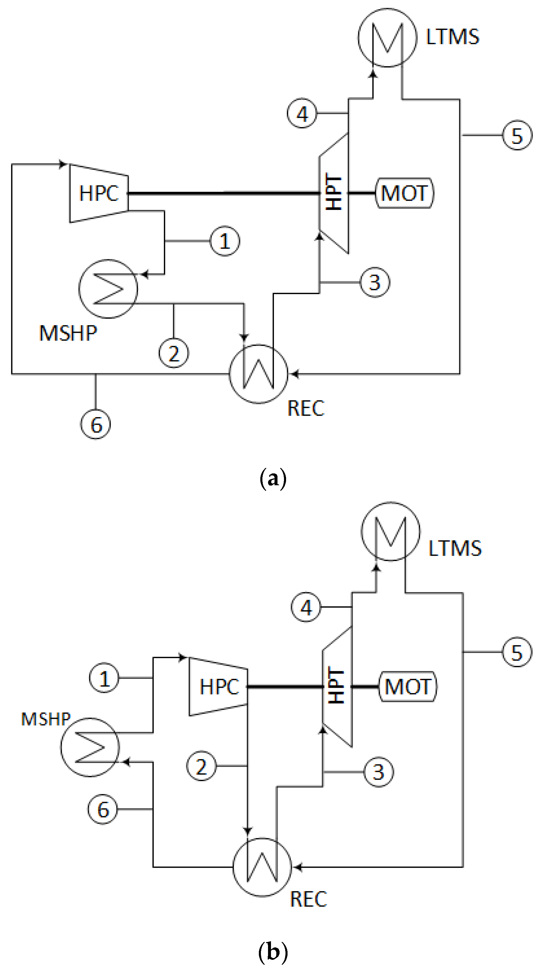
The heat engine is based on a Brayton supercritical CO2 (S-CO2) power cycle [21]. The National Renewable Energy Laboratory of the US proposes this type of power cycle for the next generation of concentrated solar power plants [33] due to its compactness and good efficiency for moderate temperatures. These cycles frequently use pressure values larger than 200 bar [34], whereas the low pressure is about 85 bar [35]. Such a pressure difference is usually withstood using printed circuit heat exchangers (PCHEs), a type of bonded plate heat exchanger with narrow channels. These narrow channels exhibit a potential issue related to using molten salts as the working fluid in both high and low-temperature storage systems [29]. To avoid this issue, a modification of this cycle is proposed in [30] by relocating the heating supply downstream of the turbine, which is the low-pressure side. This solution uses a shell and tube heat exchanger where the salts flow through the shell and the CO2 inside the tubes. Figure 2 shows the conventional (a) and the modified (b) layouts.
High efficiencies achieved by S-CO2 power cycles [21] are based on the closeness of the compressor inlet to the critical point (31.1 °C and 73.8 bar), thus reducing the compression work. Such closeness might produce substantial variations in density, which can be moderated by selecting the compressor inlet pressure at 85 bar, thus maintaining a trade-off between its stable operation and reduced compression consumption [30]. Another issue that may occur in the compressor is phase-change phenomena derived from local flow accelerations. Operation in the two-phase region can affect the compressor performance and produce erosion and degradation of some parts. To prevent premature power cycle malfunctions, it is imperative to meticulously design the main compressor, taking into account the mentioned challenges.
Moreover, the closeness to the critical point also entails another issue in a simply recuperated Brayton cycle. The specific heat of CO2 at the low-pressure stream in the recuperator is lower than the one in the high-pressure stream, thus producing an unbalanced profile of temperatures which avoids obtaining the maximum performance of the recovery process. This issue is well known and solved by partitioning the recuperator into two units, leading to the so-called re-compression cycle [21].
Analysing Figure 2b, which represents the heat engine used in the present work, the CO2 leaving the turbine (HET) takes the thermal energy from the molten salts in the molten salts/CO2 heat exchanger (MSHE) (8–9) and transfers it to the cold stream (16–7) in the high-temperature recuperator (HTR), reaching the condition of the turbine inlet. Once the hot stream has left the HTR, it transfers thermal energy again (10–11) in the low-temperature recuperator (LTR) to the cold stream (13–14). It can be observed that the cold mass flow rate in the LTR (high-pressure stream) is lower than the mass flow rate of the hot stream (low-pressure steam). This is a key factor in re-compression cycles, pursuing balance in the LTR, as the high-pressure stream exhibits higher specific heat than the low-pressure stream, as mentioned before. The mass flow rate division is done in the inlet (11) of the precooler (PC). After the splitting, the main flow is cooled (11–12) and compressed (12–13) in the main compressor (MC), whereas the rest of the flow (14–15) is sent directly to the auxiliary compressor (AC). As this stream is compressed without previous cooling, it reaches a suitable temperature to be mixed with the cold stream that leaves the LTR (14–15–16) to constitute the cold stream entering the HTR.
The isentropic efficiency of the turbine was set to 92%, and for both compressors we assumed a value of 88% [34]. The temperature approach in HTR was taken as 5 K and in LTR as 5.5 K. The approach temperature in the MSHE was set to 10 K. The main compressor outlet pressure is 300 bar, with 35 °C and 85 bar at its inlet. Pressure drops of 50 kPa were considered in each stream of the heat exchangers [30].

2.3. Heat Pump

A reverse Brayton cycle with supercritical CO2 as a working fluid was also chosen for the heat pump. This choice aims to design a high-temperature heat pump that takes heat from 300 °C to 400 °C (produced by the solar field) and delivers it between 400 °C to 600 °C. The thermal energy in both cases is exchanged with molten salts. Thus, a sensible heat transfer profile is desirable in the working fluid of the heat pump. For these reasons, a reverse Brayton cycle was selected. As in the heat engine case, PCHEs are the best option for the conventional cycle. However, in this study, they were replaced by shell and tube heat exchangers in the absorbing and delivering heat processes to overcome clogging issues with the salts. Figure 3 shows a conventional recuperated reverse Brayton cycle (Figure 3a) and the modified version adopted in the current project (Figure 3b), where both molten salt heat exchangers (LTMS and MSHP) are in the low-pressure side of the cycle due to the allocation of the MSHP upstream the compressor. Remarkably, the conventional reverse Brayton cycle is a simple recuperated one, without re-compression. It operates far from the critical point, so a nearly ideal gas behaviour is expected. This hypothesis is checked later using the property diagrams of the cycle.
The description of the cycle is as follows: the low-pressure and low-temperature stream (4) leaving the turbine (HPT) takes heat from the low-temperature reservoir in the molten salts/CO2 heat exchanger (LTMS). A second stage of heating occurs (5–6) in the recuperator (REC), taking advantage of the high temperature of the stream leaving the compressor (2–3). Then, the low-pressure stream, at high temperature after these two heating stages, supplies thermal energy to the hot sink (6–1) through the CO2/molten salt heat exchanger (MSHP). After that, the low-pressure stream is suctioned by the compressor (HPC), increasing its pressure and temperature (1–2). After the compressor, the high-pressure stream releases heat in the recuperator (2–3), reaching the turbine inlet conditions (3).
The isentropic efficiency of the turbine and the compressor were set to 92% and 88%, respectively. The temperature approach in the recuperator was taken as 5 K. The approach temperature in the low-temperature molten salts/CO2 heat exchanger was set to 10 K. The compressor outlet pressure is 300 bar, with 415 °C and 85 bar at the inlet. Pressure drops of 50 kPa were considered in each stream of the heat exchangers [30].

2.4. Molten Salts Loops

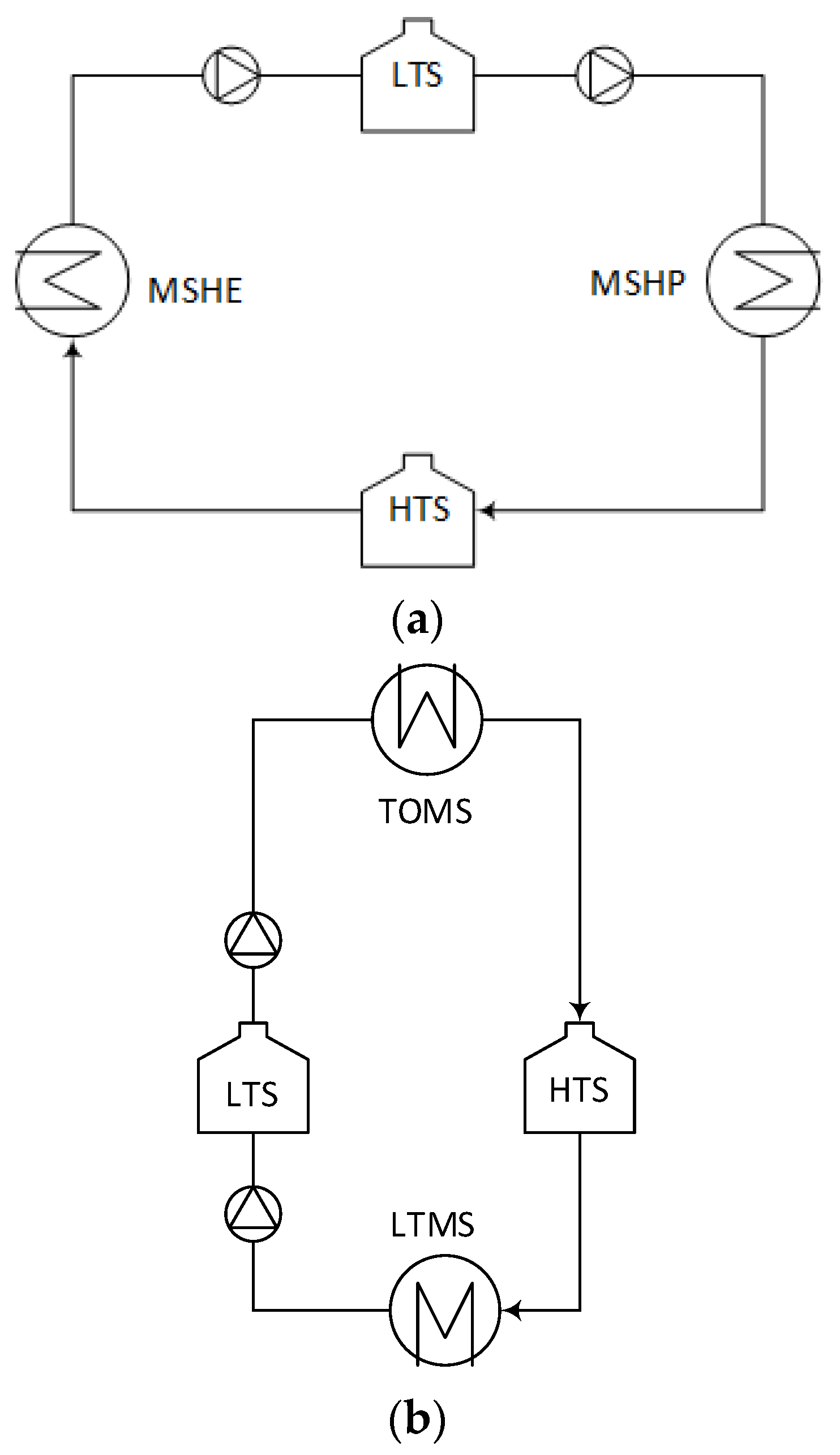
Two molten salt loops were included in the system, shown in Figure 4. The high-temperature loop (Figure 4a) stores the thermal energy at a suitable temperature to be converted into electricity by the heat engine in the discharge period. The low-temperature loop (Figure 4b) was introduced to prevent a mismatch between the solar resource and surplus power in the grid. Thus, thermal energy from the solar field might be eventually stored, waiting for a power surplus in the grid to drive the heat pump.
Solar salt (whose weight composition is 60% NaNO3 and 40% KNO3) was chosen as the working fluid, at 589 °C/405 °C in the tanks of the high-temperature loop (HTS and LTS, respectively) and 380 °C/290 °C in the low-temperature loop (HTS and LTS tanks, respectively). The molten salt proposed and the range of temperatures of the high-temperature tanks are similar to CSP’s current state-of-the-art, based on central receivers. The range of temperatures of the low-temperature tanks can be found in the current CSP, based on parabolic troughs with storage [36]. So, no corrosion or any other material-related issues are expected to occur different from those that have already been observed at CSP plants with storage.
The approach temperature in the thermal oil/molten salt heat exchanger (TOMS) was set to 10 K. Pressure drops in molten salts were considered only in the heat exchangers. The consumption of the pumps was neglected.

2.5. Solar Field

The solar field consists of parabolic trough collectors using Therminol VP1 [37] as heat transfer fluid, which is a proven and mature technology for the temperature range considered [37].
For the sizing and nominal performance of the solar field, the design point was set on the 21st of June at solar noon, at Seville (Spain), with direct normal irradiation (DNI) equal to 900 W/m2. The type of parabolic trough collector used is the Eurotrough, as shown in Table 2 [31]. The heat loss correlation used to calculate the thermal performance is provided by the manufacturer [38].
As shown in Table 2, the total number of loops is 78, each consisting of 4 collectors with 10 modules, with a total loop length equal to 490.8 m. The main parameters characterising the nominal performance of each loop are summarised in Table 3.

2.6. Sizing of Heat Exchangers

Two types of heat exchangers were used: printed circuit heat exchangers (PCHE) and shell and tube heat exchangers (STHE). As mentioned before, the former is commonly used in S-CO2 to withstand high-pressure differences; the latter is used when molten salt is one of the fluids to avoid clogging issues [30].
The sizing of the PCHEs is highly influenced by the wide variation of CO2 properties, mainly when the working conditions are close to the critical point. This requires an iterative design method based on sub-heat exchangers. A continuous variation of properties was assumed along the different sub-heat exchangers that constitute the entire unit [39]. According to the leading manufacturer [40], the maximum plate size is 600 × 1500 mm. Plates were assembled in modules with a core block assumed to have a maximum height of 600 mm, which entails a total number of 96,000 channels (48,000 per stream). This design was taken from the manufacturer [41] and was employed in a previous work with CSP technologies [30]. Up to 14 modules can be stacked in parallel in a bonding structure, constituting the largest stack (8.4 m long) [30]. The flow channels are 2 mm semicircles with a 2.5 mm pitch, and each plate has a thickness of 1.6 mm. Due to the high temperatures, Inconel alloy 617 was recommended for both REC and HTR [42]. Austenitic stainless steel 316L was selected for the rest of the PCHEs.
For each sub-heat exchanger, the overall heat transfer coefficient was evaluated by combining the convection heat transfer coefficients of both streams with the thermal conductance per unit heat transfer area between their channels, following the methodology described by Dostal [21]. The heat transfer through the surface area of the heat exchanger was then used to determine its length as a function of its perimeter. The pressure drop along the entire channel could then be evaluated for every stream. The iterative design procedure started with an initial guess of the number of channels and proceeded to assess each sub-heat exchanger until the prescribed temperatures at each of their ports were reached. The total length achieved was then used to determine the maximum pressure drop between both streams. If this maximum pressure drop is greater or lower than the prescribed value, the number of tubes is increased or decreased, respectively.
To better understand how the properties of the PCHEs vary, Figure 5a shows the Nusselt number (Nu) along the heat exchanger for both streams of the LTR (close to the critical point). Figure 5b shows the same information for the REC (far from the critical point). It can be appreciated how the low temperature and proximity to the critical point of the cold stream in the LTR produce a different trend from the other streams. The profiles at the REC, where the operation zone of the CO2 is expected to behave like an ideal gas, might be assimilated to average values.
The heat transfer to the CO2 in STHE was calculated using the Gnielinski correlation, while the pressure drop is determined using the Darcy–Weisbach equation [43]. Since the working temperatures were far from the critical point, averaged CO2 properties were considered. For the molten salt in the shell, the McAdams correlation was suggested for calculating the heat transfer, and the Kern method was used to determine the pressure drop [43].
Both the tubes and the shell were proposed to be made of stainless steel A213 Gr 347, as it is recommended for its compatibility and cost-effectiveness [33]. These STHEs are modelled as counterflow heat exchangers with one shell pass and one tube pass, except for the TOMS (thermal oil/molten salt), which uses two passes in both shell and tubes. An “E” shell type was selected according to Tubular Exchanger Manufacturers Association (TEMA) standards [44]. The minimum tube thickness is calculated according to the ASME Boiling and Pressure Vessel Code [45]. A standardised wall thickness was selected based on this lower limit and the Birmingham Wire Gage (BWG) of the tube. Other manufacturing requirements were also considered. The shell-diameter-to-tube-length ratio should be within the limits of 1/5 to 1/15. Additionally, architectural layouts and transportation constraints limited the maximum tube length to about 40 m.

2.7. Economic Model

The investment cost (fixed capital investment, FCI, according to [46]) was estimated. This cost is divided into direct and indirect costs, with the latter taken as 25% of the former. Direct costs are composed of on-site costs (equipment, piping, instrumentation, and controls) and off-site costs (land, civil works, and service facilities). Indirect costs include engineering and supervision, construction, and contingencies. In this work, the off-site costs were included in the solar field and the storage systems, whose investment is directly the direct cost. The rest of the facility was assessed from the purchased equipment cost (PEC), obtaining the on-site cost when multiplying it by 2.18 [47].
For the estimation of the heat engine and heat pump (both with Brayton supercritical CO2 cycles), a study from Sandia National Laboratory [47] for a recompression cycle of 10 MWe was taken as a basis.
The PCHEs were scaled using the number of modules, being the manufacturing unit. The escalation factor is 0.4 [46], the base PEC is USD 5 M with several modules of 4.46 for the HTR and REC, and USD 3 M and 3.1, respectively, for the rest of the PCHEs (data from 2013, [47]). The reason is that the HTR and REC operate at temperatures that demand the use of Inconel 617 alloy, whereas the other heat exchangers are manufactured in SS 316 [48].
Investment in turbomachinery, the generator in the heat engine and the motor in the heat pump were scaled according to Equations (9)–(12), taken from [49].
f W = W 10 M W 0.68
f p = p 200 b a r 0.6
f T = 3.35 + T ° C 1000 7.8 3.35 + 650 ° C 1000 7.8
P E C T M G = f W · f p · f T · 6 M $
The PEC for STHEs was estimated using the Purohit method [50]. The cost of the heat exchanger was determined based on the cost of a baseline heat exchanger, which was adjusted by taking into account various factors, such as different materials, pressures, and other design features. The cost, CE (USD), was estimated using Equation (13), supported by Equation (14). Here, Cb represents the cost of the baseline heat exchanger made of a base material (carbon steel) ($/ft2) designed for a specific pressure range (cost based on 1982 data). DSh is the shell’s inside diameter (in), p is a cost multiplier for the tube outside diameter, pitch, and layout angle, f is a cost multiplier for the TEMA-type front head, and r is a cost multiplier for the TEMA-type rear head. Ci represents the factors that adjust the base cost due to the differences from the reference heat exchanger [50], and A is the heat transfer area (ft2).
The cost estimation for the thermal energy storage systems was derived from the NREL Gen3 roadmap for CSP [33], with a two-tank solar salt system from Abengoa as a basis. The costs are reported as direct costs, that is, including both on-site and off-site expenses. The volume of the cold tank was taken as the base value (15,700 m3), and the escalation factor is 0.8. The cold tank’s base cost is USD 4.361 M, the hot tank’s is USD 10.016 M, the structural steel’s is USD 0.666 M, instrumentation’s is USD 0.212 M, the tank insulation’s is USD 3.724 M, electrical installations’ is USD 0.481 M, the foundations’ is USD 3.050 M, and the site works’ is USD 0.339 M. The salt inventory cost varies linearly, with a specific cost of USD 1100/tonne. The investment cost for the solar field was estimated, considering a specific cost of USD 152/m2 per solar aperture area (with reference to 2020) [51].
To update data from different dates, time scalation using the Chemical Engineering Plant Cost Index (CEPCI) was performed. The CEPCI in 1982 (STHE) was taken as 314, in 2013 (molten salts loops, PCHEs, and turbomachines) as 567.3, and in 2020 (date when results have been referred to) as 596.2.
C E = C b · 1 + i C i · A
C b = 6.6 1 e 7 D S h / 27 · p · f · r
Once the investment had been determined, a preliminary value for the levelised cost of storage (LCOS) was carried out. It was assumed that the electricity to drive the heat pump comes from grid surpluses, with a cost set to zero. Furthermore, maintenance costs were also neglected. With these conditions, the LCOS based on discharged energy (assuming 365 cycles of charge/discharge per year) is given by Equation (15), where W ˙ H E stands for the net power of the heat engine (discharge power), H d i s c h for the discharge hours in a day and CRF is the capital recovery factor (CRF), given in Equation (16). In this equation, wacc stands for the weighted average capital cost, taken as 7.5%, and N is the life span of the project, taken as 25 years.
L C O S = F C I · C R F W ˙ H E · H d i s c h · 365
C R F = w a c c · 1 + w a c c N 1 + w a c c N 1

3. Results

3.1. Complete Layout

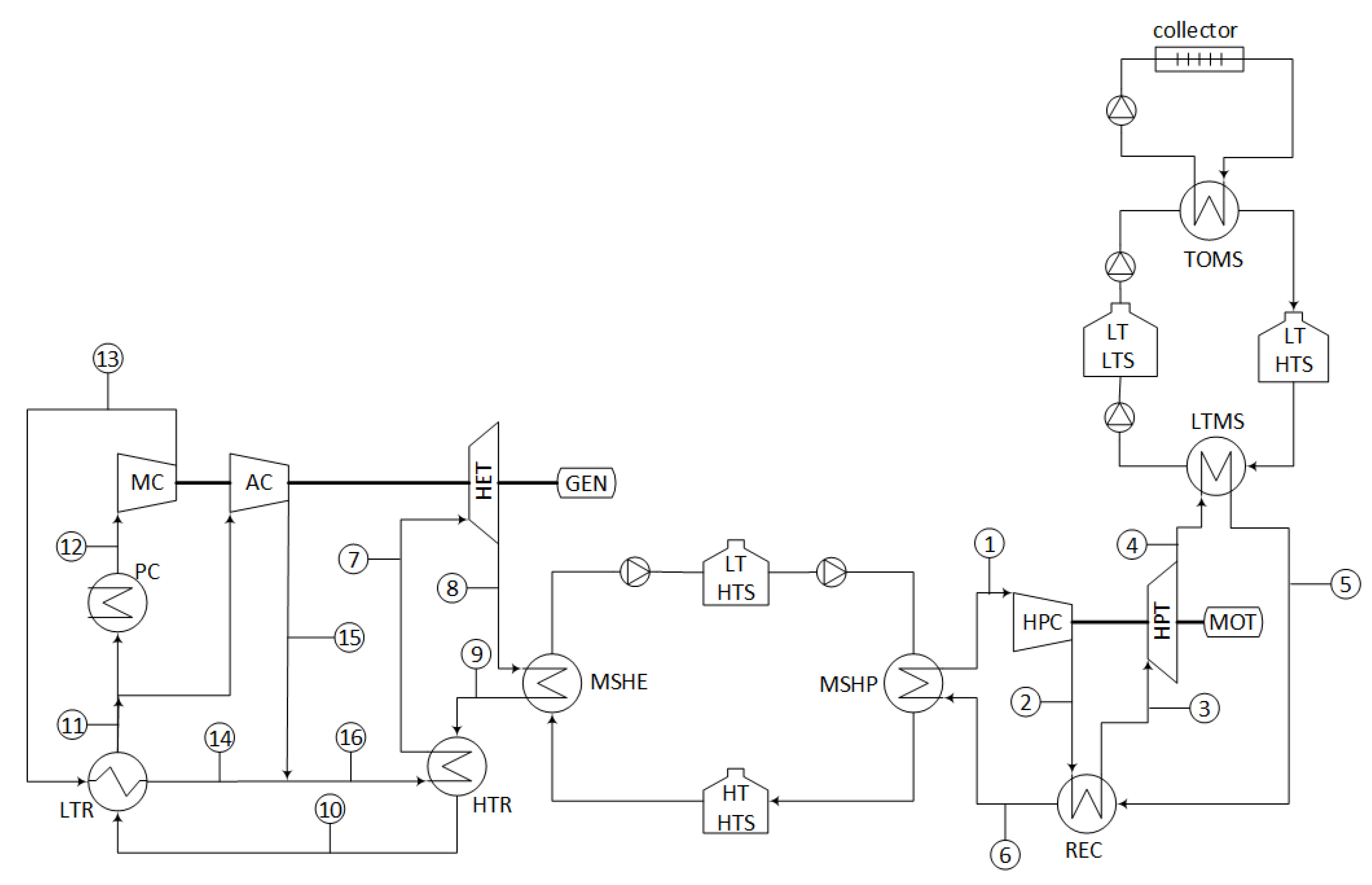
Figure 6 shows the complete layout, including the thermal engine, heat pump, two molten salt loops (high and low temperature), and the solar field (represented by one equivalent solar collector). Table 4 and Table 5 show the properties of the state points (heat pump and heat engine, respectively). Regarding the molten salt temperatures, Table 6 shows them in the storage tanks. Regarding the thermal oil in the solar field, the collector outlet temperature is 390 °C and the collector inlet temperature is 300 °C. The novelty of the proposed system, especially the allocation of the high-temperature molten salt loop heat exchangers in the heat engine and heat pump, makes it impossible to check the results with simulations of other authors. However, the model used in the current work for the heat engine is the same that was used and validated in [30]. Regarding the heat pump, a simplified version was applied to a reverse cycle.
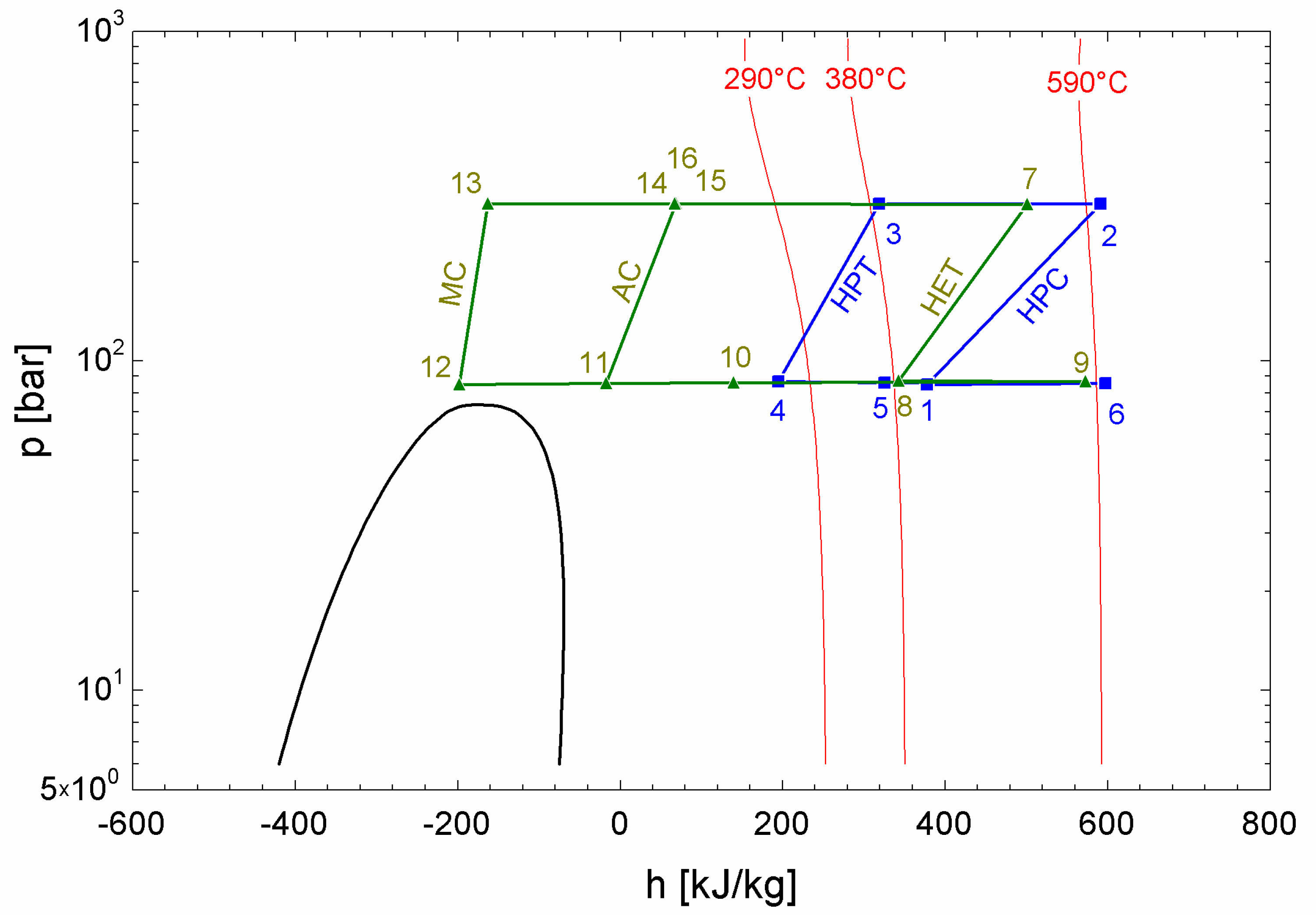
Figure 7 shows the pressure-enthalpy diagram of both the heat pump and heat engine, with each turbomachine process identified. It is worth pointing out that the compression processes in the heat engine show steeper slopes, particularly in the main compressor, due to their closeness to the critical point. However, the behaviour of the heat pump can be assimilated to a pure reverse Brayton cycle, that is, operating with an ideal gas. Figure 8a shows the heat pump cycle, whereas Figure 8b displays the heat engine cycle, both with heat exchanger identifications. In Figure 8b, the LTR enthalpy change exhibits a different length between the high and low-pressure streams (longer at the high-pressure stream). This is due to the lower mass flow ratio in the former, which compensates for its higher specific heat.
The design point was set for charge and discharge periods with the same duration for both thermal storage systems as if they were working instantaneously. At this design point, the heat engine was assumed to produce 100 MWe. The charge and discharge periods were characterised by their number of hours (Hch and Hdisch, respectively). Regarding the solar resource, the energy collected was equally distributed over constant heat duty in the so-called equivalent hours of solar resource (Hsres), accounting for variations in solar radiation. As previously explained, the low-temperature molten salt loop helps to overcome any mismatch between solar resources and grid surpluses.
The pump multiple (PM) is a factor that modulates the design size of the heat pump components according to the solar resource and charge periods, as expressed in Equation (17). Similarly, the engine multiple (EM) is a factor that modulates the design size of the heat engine components according to the solar resource and discharge periods, as expressed in Equation (18).
P M = H s r e s H c h
E M = H s r e s H d i s c h
Table 7 and Table 8 give the energy balances in both the heat pump and the heat engine, respectively. These tables include the multipliers previously defined, which will be set according to the strategy of operation (choice of charge and discharge period length).
Regarding the solar field, the heat duty of the thermal oil/molten salts heat exchanger (TOMS) was 128 MW and the mass flow rate of the thermal oil was 592.8 kg/s, both without any multiplier.

3.2. Performance

Considering the energy balances given in Table 7 and Table 8, the performance of the system is represented by Equations (19)–(21). A round-trip efficiency higher than one is reached thanks to the high COP achieved by enhancing the low-temperature source with the solar collector.
Assuming incompressible behaviour for the molten salts and cooling water, the entropy average temperature of each storage and the sink is given by Equations (22)–(24) [52]. Replacing these values in Equations (6)–(8), a maximum roundtrip efficiency of 2.92 was achieved. If both multipliers are taken as one (design case), per each hour of the solar resource, the energy input consists of 128 MWhth from the solar field and 87 MWhe charged from grid surpluses. The energy output includes 100 MWhe discharged into the grid, and 115 MWhth rejected to the cooling water.
C O P = 215 · P M · H c h 87 · P M · H c h = 215 · H s r e s 87 · H s r e s = 2.47
η H E = 100 · E M · H d i s c h 215 · E M · H d i s c h = 100 · H s r e s 215 · H s r e s = 0.4651
η r t = 100 · H s r e s 87 · H s r e s = C O P · η H E = 1.15
T L T E S = 380 290 L n 380 + 273 290 + 273 = 606.89   K
T H T E S = 589 405 L n 589 + 273 405 + 273 = 766.32   K
T 0 = 30 25 L n 30 + 273 25 + 273 = 300.49   K
The multipliers allow covering any strategy of operation. Some examples are given in Table 9. In all the cases, the solar resource period was taken as 6 h and the solar field produced 128 MW at its design point. In the case that surpluses are due to photovoltaic production (PV), a shorter charge period is expected, assumed as 3 h; if the surpluses are due to wind generation (WF), which usually occurs at night, a charge period of 6 h is proposed. Regarding the discharge periods, depending on the demand, one (1 pk) or two peaks (2 pk) periods can occur.
The main dimensions and on-site costs of HEs at different configurations of surplus origin and demand profile are given in Table 10 for PCHE and in Table 11 for STHE. Table 12 shows the on-site cost for the set of turbomachines and electrical machines (motor and generator) according to the surplus origin (heat pump) and demand profile (heat engine). Table 13 displays the direct costs of molten salt loops and solar fields. Finally, Table 14 combines the previous values according to the four configurations analysed, determining the investment and the levelised cost of storage of each one.

4. Discussion and Conclusions

A Carnot battery was proposed based on Brayton supercritical CO2 thermodynamic cycles. The architecture corresponds to a thermal integrated pumped thermal energy storage (TI-PTES). The thermal source was supplied by a solar field constituted of parabolic trough collectors, which allowed reaching an entropy average temperature of 334 °C. To overcome the possible mismatch between grid surpluses and the solar resource, a low-temperature thermal energy storage system based on a two-tank solar salt system was provided. Another two-tank system with the same molten salts was allocated to store the heat enhanced by the heat pump and consumed by the heat engine. This second storage system operates as a thermal reservoir at 493 °C (entropic average temperature). The thermal sink is a cooling water system with an entropic average temperature of 27.5 °C. With these thermal boundaries, a round-trip efficiency of 2.92 would be reached if all the systems operated totally reversibly. The proposed system achieves a round-trip efficiency of 1.15, far from the reversible case but higher than the usual storage systems [1]. Common PTES system efficiencies, without enhanced thermal sources, go down below 70% [15].
The performance of the system depends on its ability to maximise the use of thermal sources within realistic boundary restrictions. In this sense, current state-of-the-art of CSP technology parameters have been selected, and their economic impact has been evaluated. An exergy analysis is proposed in Equations (25) and (26) for the heat pump and 27 to 28 for the heat engine. In these equations, I stands for the overall irreversibility of each system and η I I represents the second law of efficiency, i.e., the ratio of exergy recovered to the exergy supplied [52]. It can be observed that the exergy conversion of each system is highly efficient, with more than 2/3 of the exergy recovered in the heat pump and more than 3/4 in the heat engine. The exergy efficiency of the heat pump is in line with [25], which suggests that a maximum temperature of 300–600 °C and an elevated source temperature can achieve 70% efficiency. The heat engine’s exergy efficiency is consistent with these types of cycles [22].
Q L T S · 1 T 0 T L T S + W P 2 S = Q H T T E S · 1 T 0 T H T T E S + I H P
η I I , H P = Q H T T E S · 1 T 0 T H T T E S Q L T S · 1 T 0 T L T S + W P 2 S = C O P · 1 T 0 T H T T E S C O P 1 · 1 T 0 T L T S + 1 = 67.87 %
Q H T T E S · 1 T 0 T H T T E S = W S 2 P + I H E
η I I , H E = W S 2 P Q H T T E S · 1 T 0 T H T T E S = η H E η H E , m a x = 76.51 %
The use of the solar field as an alternative to waste heat has allowed us to obtain a high COP in the heat pump. The required size is typical for a CSP of 50 MWe with an efficiency of 38%, without storage, as usual in Spain [53]. In fact, using the grid to power the heat pump allows for avoiding the usual oversizing of the solar field (solar multiple). It also allows allocating the investment to the components of the heat pump and heat engine instead, thus reducing it as it is strongly dependent on the solar collectors [54].
Once the low thermal source has reached a high value, a high-temperature heat pump is required. This challenge was addressed using a reverse Brayton cycle with supercritical CO2. It is well known that this kind of cycle suits well with intermediate to high temperatures [55], and the turbomachines avoid issues found in compression (VCHP) heat pumps. By shifting the heat-release heat exchanger to the low-pressure side, based on the authors’ proposal for heat engines [30], it is possible to use molten salts and high-pressure ratios, thereby increasing efficiency.
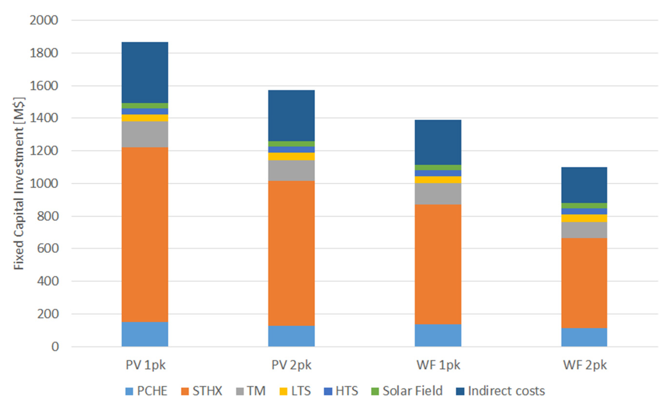
The levelised cost of storage ranged from USD 376/MWh to USD 639/MWh. The basic configuration (6 h charging and 6 h discharging) achieved the lowest cost (USD 376/MWh), which is comparable to current Li-ion batteries [26]. However, a cost range of USD 120/MWh to USD 250/MWh is expected in 2030 for batteries. These values indicate that the cost of the proposed system is too high. To find ways to reduce the investment, a cost breakdown is shown in Figure 9. Since all configurations were sized for the same amount of discharged energy, the lower the operating time, the higher the investment required. Therefore, the highest investment occurs in PV-1pk (3 h charging/3 h discharging) and the lowest in WF-2pk (6 h charging/6 h discharging), with intermediate–high value in PV-2k and intermediate–low value in WF-1k. Figure 9 points out that the most critical cost, by far, is the investment in the shell and tube heat exchangers. Therefore, this should be the first option to explore to achieve a reasonable cost.
The most effective way to reduce investment costs associated with STHE is to replace them with hybrid printed circuit heat exchangers. In this scheme, one stream’s layers are replaced with a plate-and-fin structure, thus constituting a hybrid heat exchanger that combines a PCHE and a plate-fin heat exchanger (PFHE). This type of HE has been proposed for sodium fast reactor (SFR) generation IV nuclear reactors, where liquid metal cools the reactor by circulating through the plate-fin structure, and CO2 flows through the semi-circular channels [56]. These heat exchangers have been available from Heatric since 2006 as hybrid heat exchangers (H2X), manufactured from chemically etched sheets and corrugated fins [57]. In the current proposed application, molten salts would flow through the corrugated fins, and CO2 would flow through the semi-circular channels. Corrugated fins are expected to withstand pressures of 200–220 bar [57], so allocating H2X in the low-pressure side is suitable for these heat exchangers.
As the proposed H2X is an evolution of the PCHE, it is expected to have a similar cost. Therefore, by considering the overall investment in PCHE for the WF-2pk configuration and replacing the STHE with H2X, an estimation of the new investment can be obtained (USD 550 M), resulting in a levelised cost of storage of USD 188/MWh. The overall heat duty in all the STHEs is lower than in all the PCHEs, so a safety factor is assumed in the previous hypothesis. The resulting cost is consistent with other PTES systems based on Brayton supercritical CO2 cycles [26] and with current CSP plants without storage (USD 182/MWh) [58]. Hence, once STHEs are replaced by hybrid heat exchangers and an optimisation of the pressure drops is carried out, a reasonable levelised cost of storage is expected.
Solar salts and parabolic trough collectors have been proposed in order to limit investment costs, focusing on the technological challenge in the Brayton supercritical CO2 cycles. In this sense, the molten salt heat exchangers have been identified as the key cost element, and the hybrid heat exchangers have been proposed as a solution that should be explored. Once this option is assessed, the next steps in cost reduction will involve optimising pressure drops of printed and hybrid heat exchangers, and finding a trade-off between cost and efficiency. In future works, using a central receiver with a heliostats field might be analysed, replacing the solar salt in the high-temperature loop with a ternary salt [59] to withstand higher temperatures. With such an upgrade, higher efficiencies in both the heat pump and the heat engine are expected, substantially increasing the round-trip efficiency.

Author Contributions

Conceptualisation, J.I.L., A.M.-C. and E.A.; formal analysis, E.A. and M.J.M.; funding acquisition, E.A.; investigation, J.I.L. and A.C.; methodology, E.A., M.J.M. and A.C.; project administration, J.I.L. and E.A.; resources, E.A.; software, A.C.; supervision, J.I.L.; validation, J.I.L., A.C. and J.R.P.-D.; visualisation, J.R.P.-D.; writing—original draft, J.I.L. and A.M.-C.; writing—review and editing, E.A., A.C. and J.R.P.-D. All authors have read and agreed to the published version of the manuscript.

Funding

This research was funded by Rafael Mariño, Chair on New Energy Technologies of Comillas Pontifical University.

Data Availability Statement

Data sharing not applicable.

Conflicts of Interest

The authors declare no conflict of interest. The funders had no role in the design of the study; in the writing of the manuscript; or in the decision to publish the results.

References

  1. Dumont, O.; Lemort, V. Mapping of performance of pumped thermal energy storage (Carnot battery) using waste heat recovery. Energy 2020, 211, 118963. [Google Scholar] [CrossRef]
  2. Frate, G.F.; Ferrari, L.; Desideri, U. Rankine Carnot batteries with the integration of thermal energy sources: A review. Energies 2020, 13, 4766. [Google Scholar] [CrossRef]
  3. Dumont, O.; Frate, G.F.; Pillai, A.; Lecompte, S.; De Paepe, M.; Lemort, V. Carnot battery technology: A state-of-the-art review. J. Energy Storage 2020, 32, 101756. [Google Scholar] [CrossRef]
  4. Zhang, M.; Shi, L.; Hu, P.; Pei, G.; Shu, G. Carnot battery system integrated with low-grade waste heat recovery: Toward high energy storage efficiency. J. Energy Storage 2023, 57, 106234. [Google Scholar] [CrossRef]
  5. Zhao, D.; Sun, S.; Alavi, H. Simulation and optimization of a Carnot battery process including a heat pump/organic Rankine cycle with considering the role of the regenerator. Int. J. Low-Carbon Technol. 2022, 17, 870–878. [Google Scholar] [CrossRef]
  6. Frate, G.F.; Ferrari, L.; Desideri, U. Multi-Criteria Economic Analysis of a Pumped Thermal Electricity Storage (PTES) With Thermal Integration. Front. Energy Res. 2020, 8, 53. [Google Scholar] [CrossRef]
  7. Eppinger, B.; Muradi, M.; Scharrer, D.; Zigan, L.; Bazan, P.; German, R.; Will, S. Simulation of the part load behavior of combined heat pump-organic rankine cycle systems. Energies 2021, 14, 3870. [Google Scholar] [CrossRef]
  8. Frate, G.F.; Baccioli, A.; Bernardini, L.; Ferrari, L. Assessment of the off-design performance of a solar thermally-integrated pumped-thermal energy storage. Renew. Energy 2022, 201, 636–650. [Google Scholar] [CrossRef]
  9. Redelinghuys, L.G.; McGregor, C. Carnot battery application in a parabolic trough concentrating solar power plant: System modelling, validation and analyses on the interplay between stored energies. J. Energy Storage 2023, 60, 106545. [Google Scholar] [CrossRef]
  10. Zhao, Y.; Song, J.; Liu, M.; Zhao, Y.; Olympios, A.V.; Sapin, P.; Yan, J.; Markides, C.N. Thermo-economic assessments of pumped-thermal electricity storage systems employing sensible heat storage materials. Renew. Energy 2022, 186, 431–456. [Google Scholar] [CrossRef]
  11. Zhao, Y.-L.; Wang, C.Y.; Liu, M.; Chong, D.T.; Markides, C.N.; Yan, J.J. Configuration Optimization of Carnot Battery Energy Storage System Based on Transcritical Cycles. J. Eng. Thermophys. 2021, 42, 1659–1666. [Google Scholar]
  12. Steinmann, W.D.; Jockenhöfer, H.; Bauer, D. Thermodynamic Analysis of High-Temperature Carnot Battery Concepts. Energy Technol. 2020, 8, 1900895. [Google Scholar] [CrossRef]
  13. Frate, G.F.; Pettinari, M.; Di Pino Incognito, E.; Costanzi, R.; Ferrari, L. Dynamic Modelling of a Brayton Ptes System. In Proceedings of the ASME Turbo Expo, Rotterdam, The Netherlands, 13–17 June 2022; Volume 4, p. V004T07A013. [Google Scholar]
  14. Rindt, K.; Hrdlička, F.; Novotný, V. Preliminary prospects of a Carnot-battery based on a supercritical CO2 Brayton cycle. Acta Polytech. 2021, 61, 644–660. [Google Scholar] [CrossRef]
  15. Novotny, V.; Basta, V.; Smola, P.; Spale, J. Review of Carnot Battery Technology Commercial Development. Energies 2022, 15, 647. [Google Scholar] [CrossRef]
  16. Steger, D.; Regensburger, C.; Eppinger, B.; Will, S.; Karl, J.; Schlücker, E. Design aspects of a reversible heat pump—Organic rankine cycle pilot plant for energy storage. Energy 2020, 208, 118216. [Google Scholar] [CrossRef]
  17. Eppinger, B.; Steger, D.; Regensburger, C.; Karl, J.; Schlücker, E.; Will, S. Carnot battery: Simulation and design of a reversible heat pump-organic Rankine cycle pilot plant. Appl. Energy 2021, 288, 116650. [Google Scholar] [CrossRef]
  18. Trebilcock, F.; Ramirez, M.; Pascual, C.; Weller, T.; Lecompte, S.; Hassan, A.H. Development of a compressed heat energy storage system prototype, Refrigeration Science and Technology. In Proceedings of the IIR Rankine International Conference on Advances in Cooling, Heating and Power Generation, Rankine 2020, London, UK, 27–21 July 2020; p. 168985. [Google Scholar]
  19. Blanquiceth, J.; Cardemil, J.M.; Henríquez, M.; Escobar, R. Thermodynamic evaluation of a pumped thermal electricity storage system integrated with large-scale thermal power plants. Renew. Sustain. Energy Rev. 2023, 175, 113134. [Google Scholar] [CrossRef]
  20. Reyes-Belmonte, M.A.; Guédez, R.; Montes, M.J. Bibliometric análisis on supercritical CO2 power cycles for Concentrating Solar Power applications. Entropy 2021, 23, 1289. [Google Scholar] [CrossRef] [PubMed]
  21. Dostal, V. A Supercritical Carbon Dioxide Cycle for Next Generation Nuclear Reactors. Doctoral Thesis, Institute of Technology, Cambridge, MA, USA, 2004. [Google Scholar]
  22. Chen, R.; Romero, M.; González-Aguilar, J.; Rivense, F.; Rao, Z.; Laio, S. Design and off-design performance comparison of supercritical carbon dioxide Brayton cycles for particle-based high temperature concentrating solar power plants. Energy Convers. Manag. 2021, 232, 113870. [Google Scholar] [CrossRef]
  23. Reyes-Belmonte, M.A.; Sebastián, A.; Romero, M.; González-Aguilar, J. Optimziation of a recompression supercritical carbon dioxide cycle for an innovative central receiver solar power plant. Energy 2016, 112, 17–27. [Google Scholar] [CrossRef]
  24. Muñoz, M.; Rovira, A.; Montes, M.J. Thermodynamic cycles for solar thermal power plants: A review. WIREs Energy Environ. 2022, 11, e420. [Google Scholar] [CrossRef]
  25. Vinnemeier, P.; Wirsum, M.; Malpiece, D.; Bove, R. Integration of heat pumps into thermal plants for creation of large-scale electricity storage capacities. Appl. Energy 2016, 184, 506–522. [Google Scholar] [CrossRef]
  26. Tafur-Escanta, P.; Valencia-Chapi, R.; López-Guillem, M.; Fierros-Peraza, O.; Muñoz-Antón, J. Electrical energy storage using a supercritical CO2 heat pump. Energy Resports 2022, 8, 502–507. [Google Scholar] [CrossRef]
  27. Aga, V.; Conte, E.; Carroni, R.; Burcker, B.; Ramond, M. Supercritical CO2-based het pump cycle for electrical energy storage for utility scale dispatchable renewable energy power plants. In Proceedings of the 5th International Symposium–Supercritical CO2 Power Cycles, San Antonio, TX, USA, 28–31 March 2016. [Google Scholar]
  28. Mahdi, Z.; Dersch, J.; Schmitz, P.; Dieckmann, S.; Chico, R.A.; Teixeira, C.; Herrmann, U.; Schwager, C.; Schmitz, M.; Gilen, H.; et al. Technical Assessment of Brayton Cycle Heat Pumps for the Integration in Hybrid PV-CSP Power Plants. AIP Conf. Proc. 2022, 2445, 030014. [Google Scholar]
  29. Sabharwall, P.; Clark, D.; Glazoff, M.; Zheng, G.; Sridharan, K.; Anderson, M. Advanced heat exchangers development for molten salts. Nucl. Eng. Des. 2014, 280, 42–56. [Google Scholar] [CrossRef]
  30. Linares, J.I.; Montes, M.J.; Cantizano, A.; Sánchez, C. A novel supercritical CO2 recompression Brayton power cycle for power tower concentrating solar plants. Appl. Energy 2020, 263, 114644. [Google Scholar] [CrossRef]
  31. Montes, M.J.; Abánades, A.; Martínez-Val, J.M.; Valdés, M. Solar multiple optimization for a solar-only thermal power plant, using oil as heat transfer fluid in the parabolic trough collectors. Sol. Energy 2009, 83, 2165–2176. [Google Scholar] [CrossRef]
  32. Klein, S.A.; Nellis, G.F. Mastering EES, F-Chart Software, Edition 63. Available online: http://www.fchartsoftware.com/ees/mastering-ees.php (accessed on 1 February 2023).
  33. Mehos, M.; Turchi, C.; Vidal, J.; Wagner, M.; Ho, Z.; Kolb, W.; Andraka, C.; Kruizenga, A. Concentrating Solar Power Gen3 Demonstration Roadmap; NREL/TP-5500-67464; NREL: Golden, CO, USA, 2017. [Google Scholar]
  34. Bahamonde-Noriega, J.S. Design Method for S-CO2 Gas Turbine Power Plants. Master’s Dissertation, Delft University of Technology, Delft, The Netherlands, 2012. [Google Scholar]
  35. Moisseytsev, A.; Sienicki, J.J. Investigation of alternative layouts for the supercritical carbon dioxide Brayton cycle for a sodium-cooled fast reactor. Nucl. Eng. Des. 2009, 239, 1362–1371. [Google Scholar] [CrossRef]
  36. Available online: https://www.solarpaces-conference.org/ (accessed on 1 February 2023).
  37. Therminol. 2023. Available online: https://www.therminol.com/heat-transfer-fluids (accessed on 1 February 2023).
  38. EURO. EuroTrough Project; Final Public Report, European Commission Contract No. JOR3-CT98-00231, Sevilla/Almería/Brussels; EURO: Frankfurt am Main, Germany, 2001. [Google Scholar]
  39. Serrano, I.P.; Cantizano, A.; Linares, J.I.; Moratilla, B.Y. Modeling and sizing of the heat exchangers of a new supercritical CO2 Brayton power cycle for energy conversion for fusion reactors. Fusion Eng. Des. 2014, 89, 1905–1908. [Google Scholar] [CrossRef]
  40. Available online: https://www.heatric.com/ (accessed on 1 February 2023).
  41. Pierres, R.L.; Southall, D.; Osborne, S. Impact of Mechanical Design Issues on Printed Circuit Heat Exchangers. In Proceedings of the 3rd SCO2 Power Cycle Symposium, Boulder, CO, USA, 19–20 September 2019. [Google Scholar]
  42. Li, X.; Smith, T.; Kininmont, D.; Dewson, S. Materials for Nuclear Diffusion-Bonded Compact Heat Exchangers. In Proceedings of the ICAPP’09, Tokyo, Japan, 10–14 May 2009. [Google Scholar]
  43. Kakaç, S.; Liu, H.; Pramuanjaroenkij, A. Heat Exchangers: Selection, Rating, and Thermal Design, 3rd ed.; CRC Press: Boca Raton, FL, USA, 2012; ISBN 978-1- 4398-4990-3. [Google Scholar]
  44. TEMA. Standards of the Tubular Exchanger Manufacturers Association, 8th ed.; TEMA (Tubular Exchanger Manufacturers Association): Tarrytown, NY, USA, 1999. [Google Scholar]
  45. ASME. Boiling and Pressure Vessel Code; ASME: New York, NY, USA, 2019. [Google Scholar]
  46. Bejan, A.; Tsatsaronis, G.; Moran, M. Thermal Design & Optimization; Wiley: New York, NY, USA, 1996. [Google Scholar]
  47. Fleming, D.D.; Conboy, T.M.; Pasch, J.J.; Wright, S.A.; Rochau, G.E.; Fuller, R.L. Scaling Considerations for a Multi-Megawatt Class Supercritical CO2 Brayton Cycle and Commercialization; Sandia Report Sand2013-9106; OSTI: Oak Ridge, TN, USA, 2013. [Google Scholar]
  48. Southall, D.; Pierres, R.L.; Dewson, S.J. Design considerations for compact heat exchangers. In Proceedings of the ICAPP ’08, Anaheim, CA, USA, 8–12 June 2008. [Google Scholar]
  49. Driscoll, M.J.; Hejzlar, P. 300 MWe Supercritical CO2 Plant Layout and Design; MIT-GFR-014; MIT Nuclear Engineering Department: Cambridge, MA, USA, 2004. [Google Scholar]
  50. Purohit, G.P. Estimating costs of shell-and-tube heat exchangers. Chem. Eng. 1983, 22, 56–67. [Google Scholar]
  51. Kurup, P.; Glynn, S.; Akar, S. Manufacturing cost analysis of advanced parabolic trough collector. AIP Conf. Proc. 2022, 2445, 02006. [Google Scholar]
  52. Bejan, A. Advanced Engineering Thermodynamics; John Wiley & Sons: New York, NY, USA, 1997. [Google Scholar]
  53. NREL Concentrating Solar Power Projects in Spain. Available online: https://solarpaces.nrel.gov/by-country/ES (accessed on 1 February 2023).
  54. Blair, N.; Diorio, N.; Freeman, J.; Gilman, P.; Janzou, S.; Neises, T.; Wagner, M. System Advisor Model (SAM) General Description System Advisor Model; NREL/TP-6A20-70414; OSTI: Oak Ridge, TN, USA, 2018. [Google Scholar]
  55. Pérez-Pichel, G.; Linares, J.I.; Herranz, L.E.; Moratilla, B.Y. Thermal analysis of supercritical CO2 power cycles: Assessment of their suitability to the forthcoming sodium fast reactors. Nucl. Eng. Des. 2012, 250, 23–34. [Google Scholar] [CrossRef]
  56. Saranam, V.R.; Paul, B.K. Feasibility of using diffusion bonding for producing hybrid printed circuit heat exchangers for nuclear energy applications. Procedia Manuf. 2018, 26, 560. [Google Scholar] [CrossRef]
  57. Southall, D.; Dewson, S.J. Innovative compact heat exchangers. In Proceedings of the ICAPP ’10, San Diego, CA, USA, 13–17 June 2010; p. 10300. [Google Scholar]
  58. International Renewable Energy Agency (IRENA). Renewable Power Generation Costs in 2019; IRENA: Masdar City, United Arab Emirates, 2020; ISBN 978-92-9260-040-2. [Google Scholar]
  59. Turchi, C.S.; Vidal, J.; Bauer, M. Molten salt power towers operating at 600–650 °C: Salt selection and cost benefits. Sol. Energy 2018, 164, 38–46. [Google Scholar] [CrossRef]
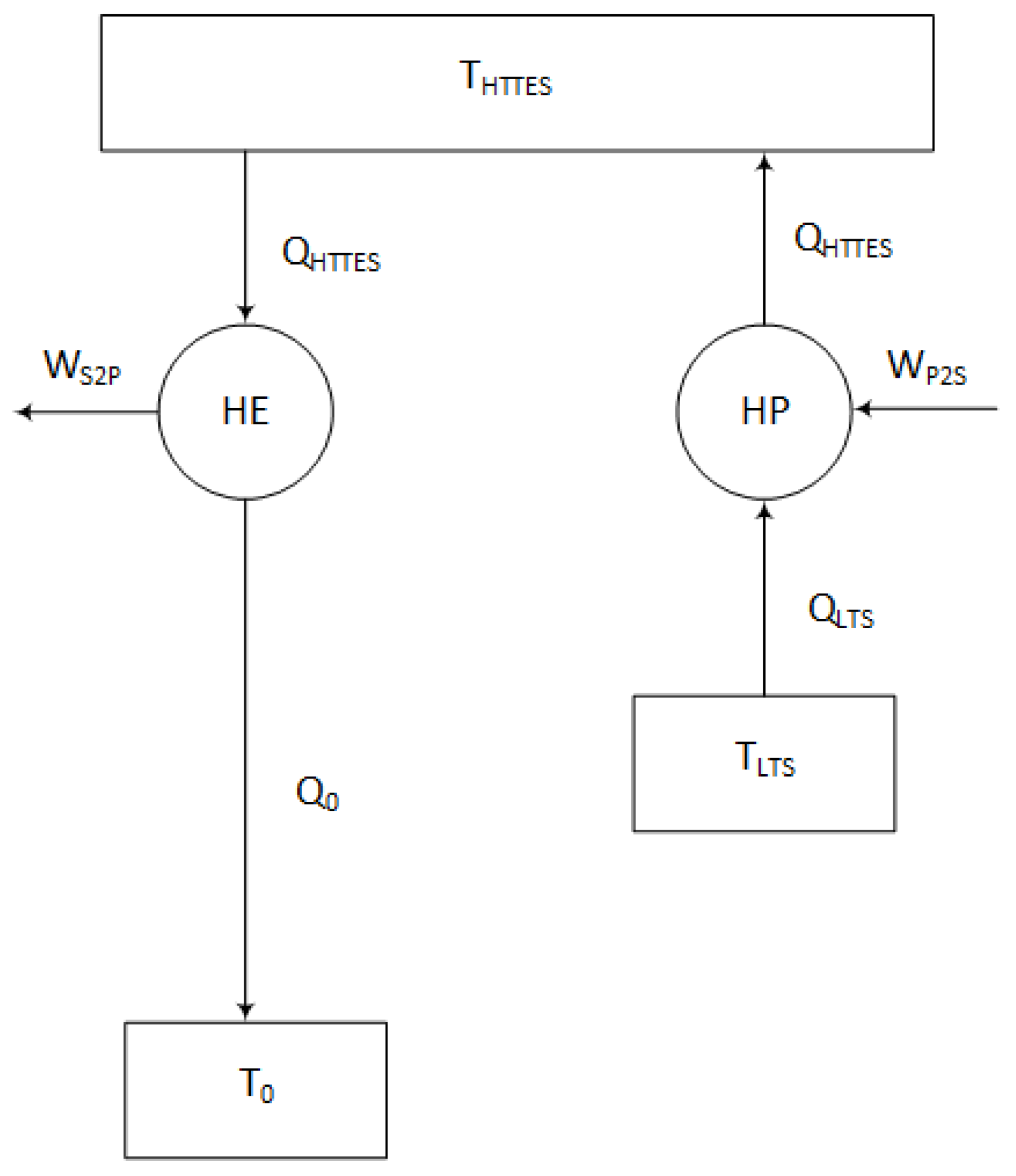
Figure 1. Conceptual diagram of a thermally integrated pumped thermal energy storage (TI-PTES) or Carnot Battery.
Energies 16 03871 g001
Figure 2. Power cycles (heat engines) recompression layouts: (a) Conventional; (b) Modified.
Energies 16 03871 g002
Figure 3. Reverse Brayton cycles (heat pumps) layouts: (a) conventional; (b) modified.
Energies 16 03871 g003
Figure 4. Molten salt loops: (a) high temperature; (b) low temperature.
Energies 16 03871 g004
Figure 5. Nusselt number: (a) LTR (146 MW) in the heat engine; (b) REC (266 MW) in the heat pump.
Energies 16 03871 g005
Figure 6. The complete layout of the proposed Carnot battery.
Energies 16 03871 g006
Figure 7. Pressure–enthalpy diagram of the proposed Carnot battery (heat pump in blue lines and heat engine in green lines).
Energies 16 03871 g007
Figure 8. Pressure–enthalpy diagrams: (a) heat pump; (b) heat engine.
Energies 16 03871 g008
Figure 9. Investment breakdown of different configurations.
Energies 16 03871 g009
Table 1. Comparison of different electrical energy storages [1].
TechnologyEnergy Density [kWh/m3]Energy Cost [$/kWh]Energy Cost [$/kW]P2P [%]Lifetime
[Years]
PHS0.5–1.55–100300–520065–8730–60
GES0.5–1.5N/AN/A70–8630–40
CAES1–122–200400–225040–9520–60
LAES50260–530500–350040–8520–40
Li-Ion B300500–2500270–150085–955–15
Flow B16–60120–1000175–10,00057–855–15
PTES0.25–6.962–107533–62770–8025–30
Table 2. Geometric and optical parameters of the solar field [31].
Number of loops in the solar field78
Number of collectors per loop4
Number of modules per collector10
Length of every module (m)12.27
Absorber tube outer diameter (m)0.07
Absorber tube inner diameter (m)0.065
Glass envelope outer diameter (m)0.115
Glass envelope inner diameter (m)0.109
Intercept factor0.92
Mirror reflectivity0.92
Glass transmissivity0.945
Solar absorptivity0.94
Peak optical efficiency0.75
Table 3. Nominal performance of the parabolic trough loop.
Mass Flow per loop (kg/s)7.6
Inlet/Outlet HTF temperature (°C)300/390
Inlet Pressure (bar)20
Heat gain per loop (MWth)1.6732
Heat loss per loop (kWth)158.56
Pressure drop per loop (bar)4.1438
Optical efficiency (%)71.99
Thermal efficiency (%)91.34
Table 4. Properties at state points (Figure 5) of the heat pump.
PointPressure (bar)Temperature (°C)Enthalpy (kJ/kg)
185.00415.0377.28
2300.0604.1590.78
3299.5389.2318.67
486.50256.0194.39
586.00370.0324.89
685.50599.1597.00
Table 5. Properties at state points (Figure 5) of the heat engine.
PointPressure (bar)Temperature (°C)Enthalpy (kJ/kg)
7299.0532.9500.51
887.00385.4342.50
986.50579.1572.58
1086.00207.2138.99
1185.5082.02−17.394
1285.0035.00−197.94
13300.076.52−163.33
14299.5201.766.166
15299.5203.368.548
16299.5202.266.925
Table 6. Temperatures of storage tanks in the molten salt loops (Figure 5).
LoopHot Tank Temperature (HT) (°C)Cold Tank Temperature (LT) (°C)
High temperature (HTS)589405
Low temperature (LTS)380290
Table 7. Energy balance at the design point of the heat pump (Figure 6). In the HE, the hot stream is designed in the first place.
ComponentHeat Duty or Power
(MW)
Mass Flow Rate
(kg/s)
Compressor (HPC)209 PM978 PM
Turbine (HPT)122 PM978 PM
Motor (MOT)87 PM---
CO2/CO2 (REC)266 PM978 PM/978 PM
Molten salts/CO2 (LTMS)128 PM941 PM/978 PM
CO2/Molten salts (MSHP)215 PM978 PM/761 PM
Table 8. Energy balance at the design point of the heat engine (Figure 6). In the HE, the hot stream is designed in the first place.
ComponentHeat Duty or Power
(MW)
Mass Flow Rate
(kg/s)
Main Compressor (MC)22 EM637 EM
Auxiliary Compressor (AC)26 EM297 EM
Turbine (HET)148 EM934 EM
Generator (GEN)100 EM---
CO2/CO2 (HTR)405 EM934 EM/934 EM
CO2/CO2 (LTR)146 EM934 EM/637 EM
Molten salts/CO2 (MSHE)215 EM761 EM/934 EM
CO2/Water (PC)115 EM637 EM/5502 EM
Table 9. Operation strategies according to the surplus origin and demand profile for 6 equivalent hours of the solar resource. Charge power (heat pump consumption) and discharge power (heat engine production) are calculated for a solar field of 128 MW.
Surplus
Origin
HchDemand
Profile
HdischPMEMCharge
Power (MW)
Discharge
Power (MW)
PV31 pk322174200
32 pk621174100
WF61 pk31287200
62 pk61187100
Table 10. Size and costs of PCHE at different configurations.
ComponentProfileHeat Duty
(MW)
Height
(m)
Number of
Modules
On-Site
Cost (USD M2020)
RECWF2663.4212843.9
PV5323.4225657.9
HTR2 pk4052.385932.2
1 pk8102.3811842.5
LTR2 pk1464.039927.5
1 pk2924.0319836.2
PC2 pk1150.541010.8
1 pk2300.542014.2
Table 11. Size and costs of STHE at different configurations.
ComponentProfileHeat Duty (MW)Length
(m)
Shell
Diameter
(m)
Number
of Units
On-Site
Cost per Unit
(USD M2020)
TOMSAll12830.23.18135.6
LTMSWF12814.83.62167.6
PV25614.83.622135
MSHPWF21539.54.261286
PV43039.54.262572
MSHE2 pk21530.24.051191
1 pk43030.24.052382
Table 12. Turbomachines and electrical machine costs for different configurations.
CycleTypeOn-Site
Cost (USD M2020)
HPWF20.4
PV32.7
HE2 pk22.4
1 pk35.9
Table 13. Molten salt loops and solar field costs.
ComponentEnergy Stored
(MWh)
Salt Inventory
(ton)
Direct Costs (USD M2020)
LTS76820,39344.0
HTS129016,46237.0
Solar Field------32.5
Table 14. Fixed capital investment and levelised cost of storage at different configurations.
Surplus
Origin
Demand
Profile
Discharge
Power (MW)
Discharge
Energy (MWh)
FCI
(USD M2020)
LCOS
(USD2020/MWh)
PV1 pk2006001865639
2 pk1006001571538
WF1 pk2006001392477
2 pk1006001098376
Disclaimer/Publisher’s Note: The statements, opinions and data contained in all publications are solely those of the individual author(s) and contributor(s) and not of MDPI and/or the editor(s). MDPI and/or the editor(s) disclaim responsibility for any injury to people or property resulting from any ideas, methods, instructions or products referred to in the content.