Article

Mechanistic Exploration of Dendrite Growth and Inhibition for Lithium Metal Batteries

1
State Key Laboratory of Complex Nonferrous Metal Resources Clean Utilization, Kunming University of Science and Technology, Kunming 650093, China
2
Kunming Metallurgical Research Institute Co., Ltd., Kunming 650093, China
*
Author to whom correspondence should be addressed.
Energies 2023, 16(9), 3745; https://doi.org/10.3390/en16093745
Submission received: 20 March 2023 / Revised: 13 April 2023 / Accepted: 24 April 2023 / Published: 27 April 2023

Abstract

:
Li metal has been considered an ideal anode in lithium batteries due to its high theoretical capacity of 3860 mAh·g−1 and lowest negative reduction potential of −3.040 V among the standard hydrogen electrodes. However, lithium dendrites can easily grow on the surface of the negative electrode during charging, which results in a short circuit of the battery and reduces its efficiency. This paper investigated dendrite growth and inhibition mechanisms in lithium metal batteries to improve battery life. The impacts of the initial nucleation spacing, surface energy anisotropy strength, and interfacial electrochemical driving force on lithium dendrite growth were analyzed with electrochemical experiments and mathematical models. The results showed that the smaller nucleation spacing inhibits the growth of dendrite side branches and reduces the roughness of lithium metal deposition on the negative electrode. A lower interfacial energy anisotropy strength can slow down the growth of dendrite tips and improve the dendrite growth structure. The growth of the dendrites is influenced by the interfacial electrochemical driving force. Reducing the nucleation overpotential can effectively inhibit the growth of lithium dendrites.

1. Introduction

The metal lithium anode with exceptionally high capacity (3860 mAh·g−1) and the most negative potential (−3.040 V vs. standard hydrogen electrode) is referred to as the “holy grail” electrode of the secondary lithium battery. However, the uncontrollable dendrite growth poses a severe safety hazard, causing internal short circuits or even causing the battery to explode during lithium metal battery charging. In addition, since lithium dendrites are continuously formed, they increase the surface area of contact between the active material and the electrolyte, significantly reducing the battery’s Coulomb efficiency. Therefore, many studies were conducted on the growth mechanism and inhibition methods of lithium dendrites, mainly focusing on structured negative electrodes [1,2], electrolytes with high salt concentrations [3,4,5], electrolyte modification [6,7], film-forming additives [8,9], electrolyte additives [10,11], non-situ solid electrolyte interface membranes [12,13,14], nano-electrolytes [15,16], and solid electrolytes [17,18]. Most of these studies used experimental methods to analyze the influencing factors of lithium dendrite growth and proposed inhibition methods to improve the performance of lithium metal batteries. However, lithium metal’s most negative reduction potential also brings high electrochemical reactivity, making it highly demanding for experimental conditions and uncertainty in experimental results, which requires further explanation and theoretical support. Therefore, studying lithium dendrites using only experimental methods is exceptionally challenging.
The numerical simulations can predict the growth characteristics of dendrites by modulating the surface properties (initial nucleation spacing, surface energy), electrochemical properties (interfacial electrochemical driving force), and transport processes (ion transfer) of negative materials. The phasefield model has been proven to describe dendrite growth quantitatively and has achieved good results in reproducing the dendrite growth characteristics and studying the physical properties of the dendrite surface, which is an effective method for solving this problem. Monroe and Newman [19] proposed the first mathematical model of dendrite tip height and growth rate with time in lithium polymer batteries based on electrochemical dendrite growth. The growth of lithium dendrites occurs primarily at the electrolyte-solid interface, and phase field methods can model this continuum of phase transition. Liang et al. [20] proposed a nonlinear phasefield model for electrodeposition and showed that lithium dendrites are fibrous and grow in parallel along the electric field direction. Ely et al. [21] developed a phasefield model for the growth kinetics of non-homogeneous lithium dendrites. Their model included electrochemical contributions from the electrolyte-dendrite interface energy and bulk phase transition-free energy. Chen et al. [22] proposed a thermodynamically consistent phasefield model that considered nonlinear reaction kinetics in the study the dendrite morphology during electrodeposition. The results showed that larger applied voltages or flat protrusions at the interface contribute to the growth of dendrite side branches and even promote unstable tip splitting.
Nowadays, numerous researchers have focused on using phase field methods to explore the mechanisms and inhibition of dendrite growth [23,24,25]. Gao et al. [26] assessed the effects of noise, internal heat, and porosity on the growth behavior of lithium dendrites. Yan et al. [27] evaluated the thermal impact of dendrite growth and showed that the normalized dendrite length decreased with increasing ambient temperature, the temperature at the dendrite-electrolyte interface increased significantly, the dendrite shifted from dendritic to sub-rhombic, and the presence of a temperature gradient prevented the formation of side branches. Yurkiv et al. [28] investigated the coupling between the stress field and lithium dendrite formation by considering the anisotropy of the elastic properties of lithium dendrites. Tan et al. [29] developed an anisotropic diffusion response model to investigate the effect of mass transport anisotropy on lithium dendrite growth and showed that interfacial anisotropy not only affects the number of lithium dendrites but also the growth morphology of lithium dendrites. However, most studies on dendrite growth inhibition consider the anisotropy effects of the elastic properties, endotherm, noise, and stress field on the dendrite growth. On the contrary, the initial nucleation spacing, surface energy anisotropy strength, and interfacial electrochemical driving force are rarely considered.
This paper uses theoretical and experimental approaches to investigate the factors affecting the growth of lithium dendrites. A nonlinear phasefield model is developed, and a custom partial differential equation is used to simulate the morphological evolution during the development of lithium dendrites. The dendrite growth mechanism of lithium metal anode materials and the influence of electrochemical characteristics on dendrite growth are discussed. Various factors of dendrite growth morphology, such as the initial nucleation spacing of dendrites, the intensity of surface energy anisotropy, and the electrochemical driving force at the interface, are explored. The phasefield model developed in this study can facilitate the further application of numerical simulation methods in analyzing battery dendrites and provide some reference value for the suppression of dendrite growth and morphology control of lithium metal battery anode.

2. Theoretical Framework

2.1. Phase-Field Equation

Figure 1a shows the schematic diagram of the lithium dendrite growth mechanism, where A represents the metal electrode, and B is the electrolyte. The anode is simplified to a surface without considering the electrode structure, and tiny ellipses are set as nucleation sites for lithium dendrites. During the charging process, lithium ions get electrons to gather and deposit at the nucleation sites to form dendrites. To describe the dynamic changes between the interface of the lithium anode and the electrolyte, the phasefield order parameter ξ is introduced. ξ = 1 indicates the lithium anode, and ξ = 0 indicates lithium ions in the electrolyte, as shown in Figure 1b. In addition, 0 < ξ < 1 indicates the liquid-solid phase transition. To simplify the model, the following assumptions are made:
(1)
The electrolyte is a dilute solution [22,30].
(2)
The electrode surface has enough electrons to participate in the reaction.
The lithium dendrite growth is modeled based on the Allen-Cahnand Butler-Volmer [31] equations, where the non-conservative phase field sequence parameter ξ is implemented through the phase field equation expressed as:
ξ t = L σ W g ξ k θ 2 ξ k θ ξ y x ξ x y + L η h ξ [ C L i + s C L i + 0 e x p ( α F η R T ) e x p ( β F η R T / R T ) ]
where Lσ is the interfacial mobility, W is the height of the energy barrier at which the reaction occurs, g ξ = W ξ 2 1 ξ 2 is the double-well function on the potential barrier, k(θ) = k0[1 + δcos(wθ)] is the surface energy anisotropy, k0 is the gradient energy coefficient, δ, and w are respectively the surface energy anisotropy strength and modulus, θ is the normal vector of the interface and the angle between the reference axes which is equal to t a n 1 ( u / y u / x ) , Lŋ is a constant describing the magnitude of the electrochemical reaction resistance, h ξ = ξ 3 6 ξ 2 15 ξ + 10 is the interpolation function, c L i + 0 is the initial lithium ion concentration, c L i + s A is the lithium-ion concentration at the electrode surface, ŋ is the electrode reaction driving force, α and β are the symmetry coefficients, F is the Faraday constant, R is the ideal gas constant, and T is the electrolyte temperature.

2.2. Lithium Ion Diffusion Equation

Lithium ions are consumed at the interface based on the Nernst-Planck equation [32]. For non-flowing liquids, the strength of the molar flux of the i-th component on the cross-section of the liquid is proportional to its thermodynamic driving force u ~ i :
J i = c i m i u ~ i ,
where ci is the concentration of component i and mi is its electromobility.
The ion electromobility can be determined from the diffusion coefficient:
m i = D i Z i R T
where Di denotes the ion diffusion coefficient, and Zi is the charge number.
The liquid phase electrochemical potential u ~ i is given by:
u ~ i = u i o + R T l n c i c i o + z i F φ , i = 1 , . , N c
where u i o is the standard chemical potential, φ(t,x) denotes the potential field with respect to time and distance, c 0 is the bulk concentration of the Li+ cations assuming that the system is an ideal dilute solution ( c i o = c 0 ). The simplification of Equation (2) yields the Nernst-Planck equation, which describes the transport of ions in the electrolyte:
J i = D i c i J i d i f f D i c i z i F φ t , x / R T J i m i g r , i = 1 , , N c
where J i d i f f and J i m i g r represent the contribution of the i-component diffusion and migration to the cross-sectional molar flux intensity, respectively.
The total amount of components i moved into a cross-section through the mass transfer process is not equal to the total amount moved out. In addition, the concentration in this cross-section changes, and the ion transfer process in the electrolyte can then be expressed as:
C L i + / t = [ D L i + C L i + + D L i + C L i + φ ( t , x ) F R T ] λ C L i + ξ t
where λ is the solid-to-liquid concentration ratio and:
D L i + ξ = D e h ξ + D s 1 h ξ
where De and Ds represent the effective diffusion coefficients of lithium ions in the electrode and electrolyte, respectively.

2.3. The Control Equation for the Electron Transmission Process

The system electrostatic potential distribution is described by Poisson’s equation [22], which takes into account the principle of electrical neutrality of the system and the influence of the current density:
[ σ ( ξ ) φ ( r , t ) ] = I r
where σ ( ξ ) is the electrical conductivity, φ ( r , t ) is the interfacial potential, and I r is the interfacial reaction current:
I r = z i F c L i + ξ / t
The conductivity σ ( ξ ) is a function of the phase field parameters:
σ ( ξ ) = σ e h ξ + σ s 1 h ξ
where σ e and σ s denote the electrode and electrolyte conductivity, respectively.

2.4. Initial Conditions and Boundary Conditions

The PDE module of COMSOL was used to solve the constructed phase field equations with the initial solid-phase lithium metal as an ellipsoid ((x − floor(x))2 + y2 = 1). The initial nucleation point was set at the bottom middle of the computational domain, and the Dirichlet boundary condition was used. In the concentration field, the electrolyte boundary concentration was set to 1, and the electrode concentration was set to 0. In the electric field, the potential at the electrode was set to 0, and the potential of the electrolyte was set to 0.1. The other relevant physical parameters are shown in Table 1.

3. Experiment

3.1. Material Synthesis

To verify the reliability of the proposed model, half-cell charge/discharge experiments were conducted to investigate the growth mechanism of lithium dendrites using a Cu-Zn alloy mesh as the working electrode. Four Cu-Zn alloy meshes with contents of Cu 65%, Zn 35%; Cu 80%, Zn 20%; Cu 90%, and Zn 10% and pure copper mesh were treated with dilute hydrochloric acid, acetone, distilled water, and anhydrous ethanol to remove the surface impurities and oxide layer, then dried and treated for use. The Cu-Zn alloy mesh (Cu 65%, Zn 35%) was placed in a tube furnace (MTI, OTF-1200X50, Hefei, China) and heated at 300, 350, 400, and 450 °C under air atmosphere for 2 h, removed and cooled to room temperature, washed with distilled water, dried, and stored in an incubator at 60 °C.

3.2. Coin Cell Assemblage and Electrochemical Testing

The semi-cell assembly sequence is the positive shell, Cu-Zn alloy mesh collector, diaphragm, lithium sheet, nickel foam, and negative shell. The cells were assembled in a glove box (Mikrouna, Super 1220/750/900, Shanghai, China) with water oxygen below 0.1 ppm and filled with argon gas. The treated Cu-Zn alloy mesh collector was used as the working electrode, and the lithium sheet was used as the counter electrode. The working electrode was pre-activated before the test to facilitate the stable formation of the solid electrolyte interfacial film. The electrolyte was 50 μL 1.0 wt% lithium nitrate (LiNO3), 1.0 mol·L−1 lithium bis (trifluoromethanesulfonate) imide (LiTFSI) in 1,3-dioxolane (DOL)/diethylene glycol dimethyl ether (DME) (1/1, v/v) solution. Polypropylene Celgard 2500 was considered for the diaphragm, with nickel foam playing a supporting and conductive role. Charge/discharge experiments were then performed in a Sunway battery test system (CT-4008T, China) with a charge/discharge settling time of 5 min, a setting current of 1 mA·cm−2, and a deposition capacity of 1 mAh·cm−2. After the experiments, the surface morphology of the lithium metal anode was observed using SEM.

3.3. Characterization

Scanning electron microscopy (SEM) images were collected using a Zeiss Gemini 300 (operating at 20 kV) to observe the micromorphology of the samples. X-ray powder diffraction (XRD) patterns of the synthesis material were measured by a D8 Bruker X-ray diffractometer working at 40 kV and equipped with graphite monochrome Cu Kα radiation (λ = 0.15418 nm) in the range 2θ = 1–80°. X-ray photoelectron spectroscopy (XPS) was performed to determine the chemical composition using a surface analysis system (Thermo Sci. ESCA LAB 250), monochromatic Al-Kα X-ray source, and calibrated with C1s binding energy of 284.8 eV.

4. Results and Discussion

4.1. Morphology and Evolution of the Lithium Dendrites

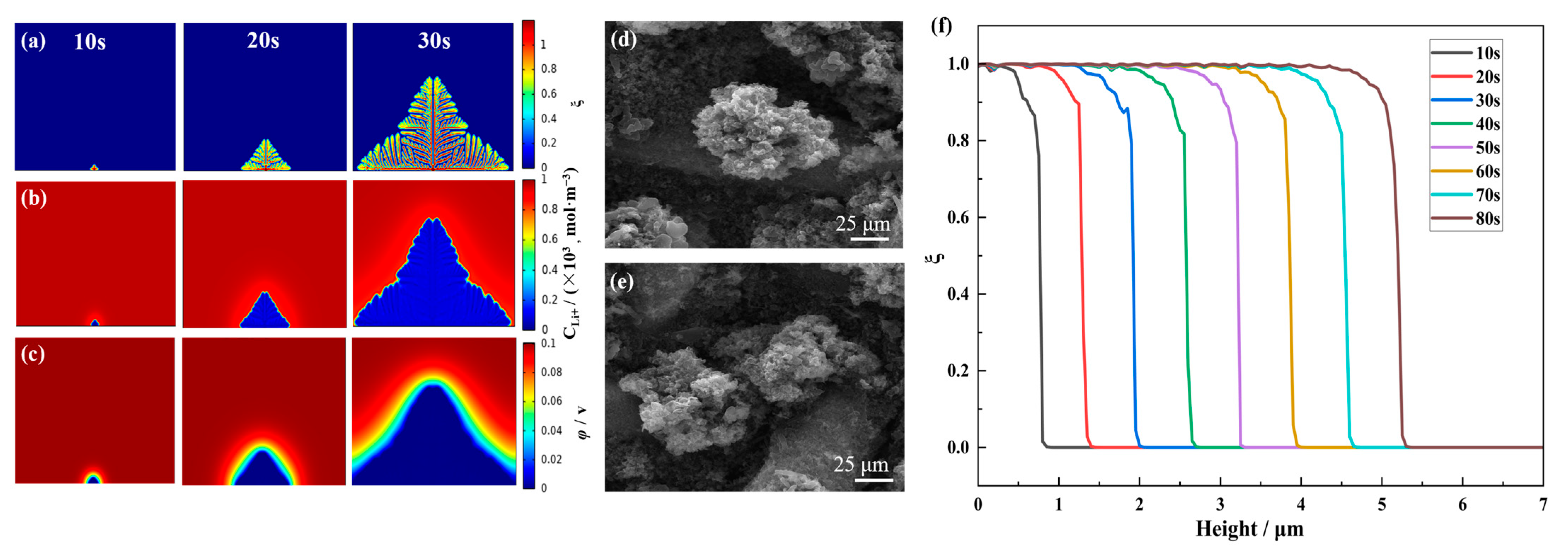
The evolution of the lithium dendrite growth with time was obtained by solving Equations (1)–(10) using COMSOL (Figure 2). Figure 2a shows the lithium dendrite growing vertically along the negative electrode toward the electrolyte with time while also dispersing around the electrolyte at a specific rate. It exhibits a gradually expanding equilateral triangular external profile in the 2D model and eventually forms a tree-like dendrite on the electrode surface, which is consistent with the experimentally derived SEM scan results, as shown in Figure 2d,e. During the dendrite growth, the lithium ions at the dendrite/electrolyte boundary are rapidly consumed, forming a significant concentration difference, as shown in Figure 2b. In addition, there is a gradient in the potential along the dendrite growth direction, with the lowest potential at the dendrite near the negative side and the highest one at the electrolyte near the positive side, as shown in Figure 2c.
The trends of lithium-ion concentration and potential changes are similar to that of dendrite growth. The variation of the dendrite height with time is shown in Figure 2f. The dendrite height continuously increases with time. When the time is extended from 10 s to 80 s, the dendrite height increases from 0.885 μm to 5.351 μm.

4.2. Influence of Different Initial Nucleation Spacings on the Morphology of the Dendrite Growth

To study the influence of different initial nucleation intervals on the dendrite growth morphology, the initial nucleation intervals (d) are set to 2.5, 1, and 0.3 μm in COMSOL. The lithium dendrite profile data are extracted from the simulation results to visually obtain the dendrite growth evolution process, as shown in Figure 3c. The simulation results show that the growth pattern of the lithium dendrites is similar to that of a single nucleation site at the early growth stage. On the contrary, when the side branches of two adjacent dendrites start to contact, due to the spatial limitation and the shrinkage of the lithium-ion receiving area (Figure 3a), the dendrites change from the divergent growth pattern to the vertical growth pattern, as shown in Figure 3b. When the nucleation interval decreases from 2.5 μm to 1 μm, the nucleation density of lithium dendrites increases, and the side branches shorten from 1.5 μm to 0.5 μm. When the nucleation interval decreases to 0.3 μm, the side branches disappear, and the dendrites grow vertically in a rod shape.
Figure 3d shows the lithium metal deposition capacity (actual deposition capacity = 1 mAh·cm−2 × deposition capacity as a percentage) versus deposition surface roughness for different initial nucleation spacings. It can be seen that the deposition capacity of the lithium ions and the roughness increase with time for all the initial nucleation spacings. The larger the initial nucleation spacing, the rougher the deposition surface. At the charging time of 80 s, for d = 2.5, 1, and 0.3 μm, the surface roughness is 2.9, 1.24, and 0.2, respectively. It then tends to a stable value of 0.20 μm after 10 s with slight variation.
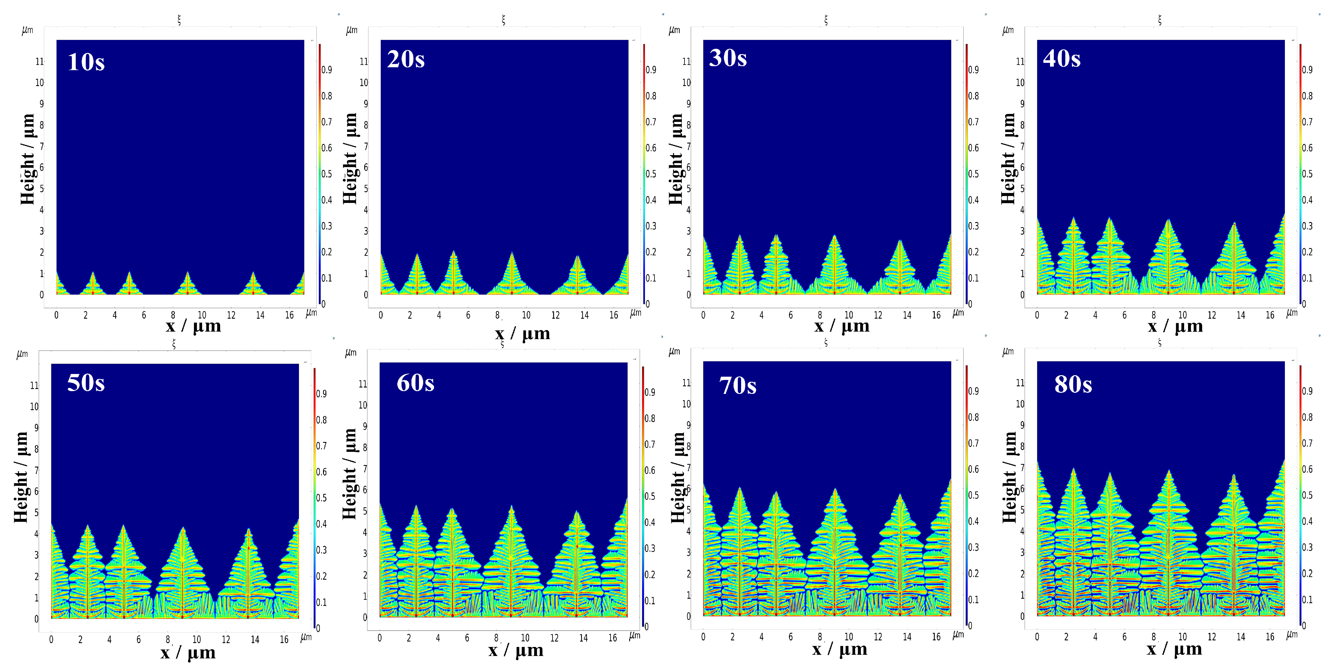
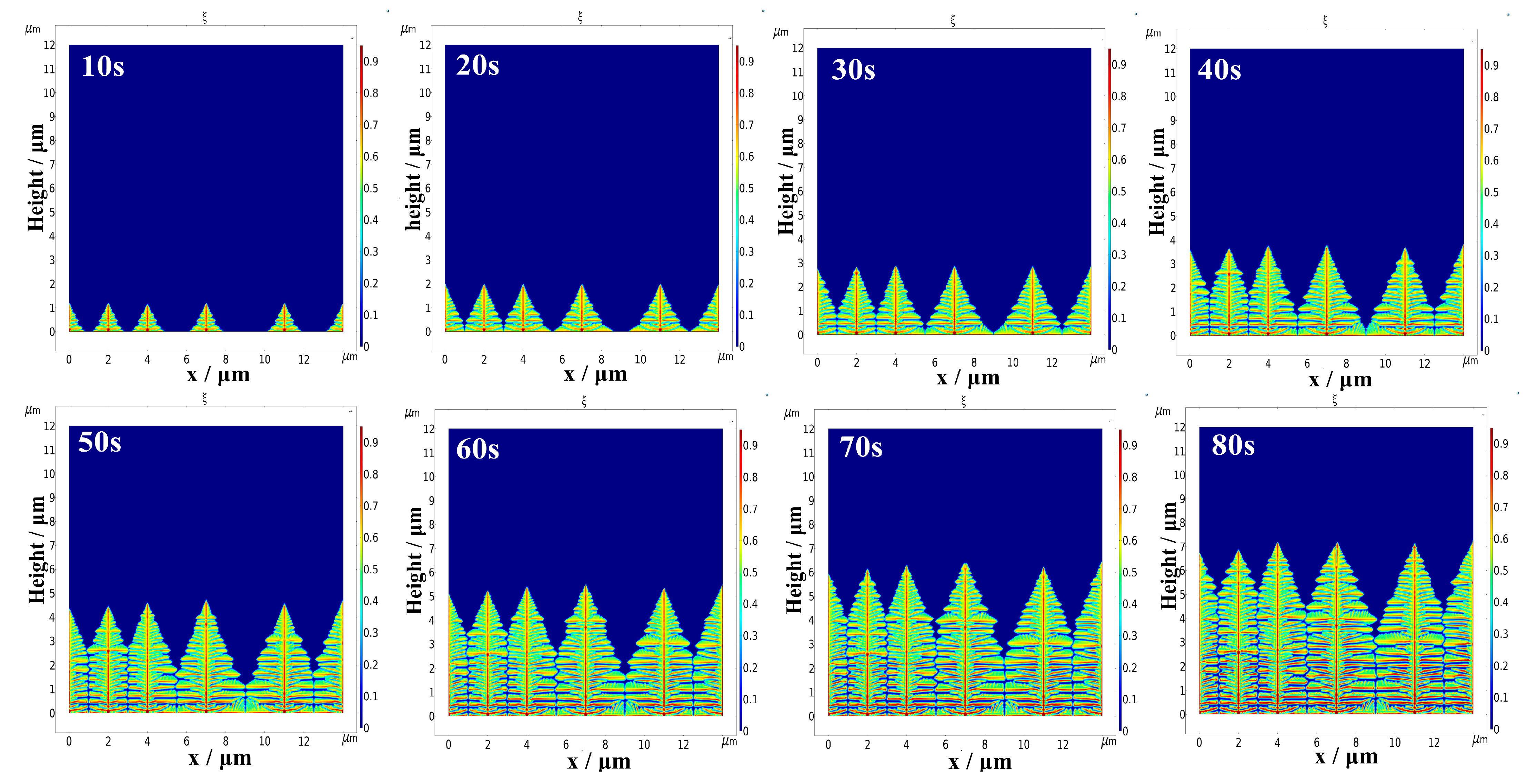
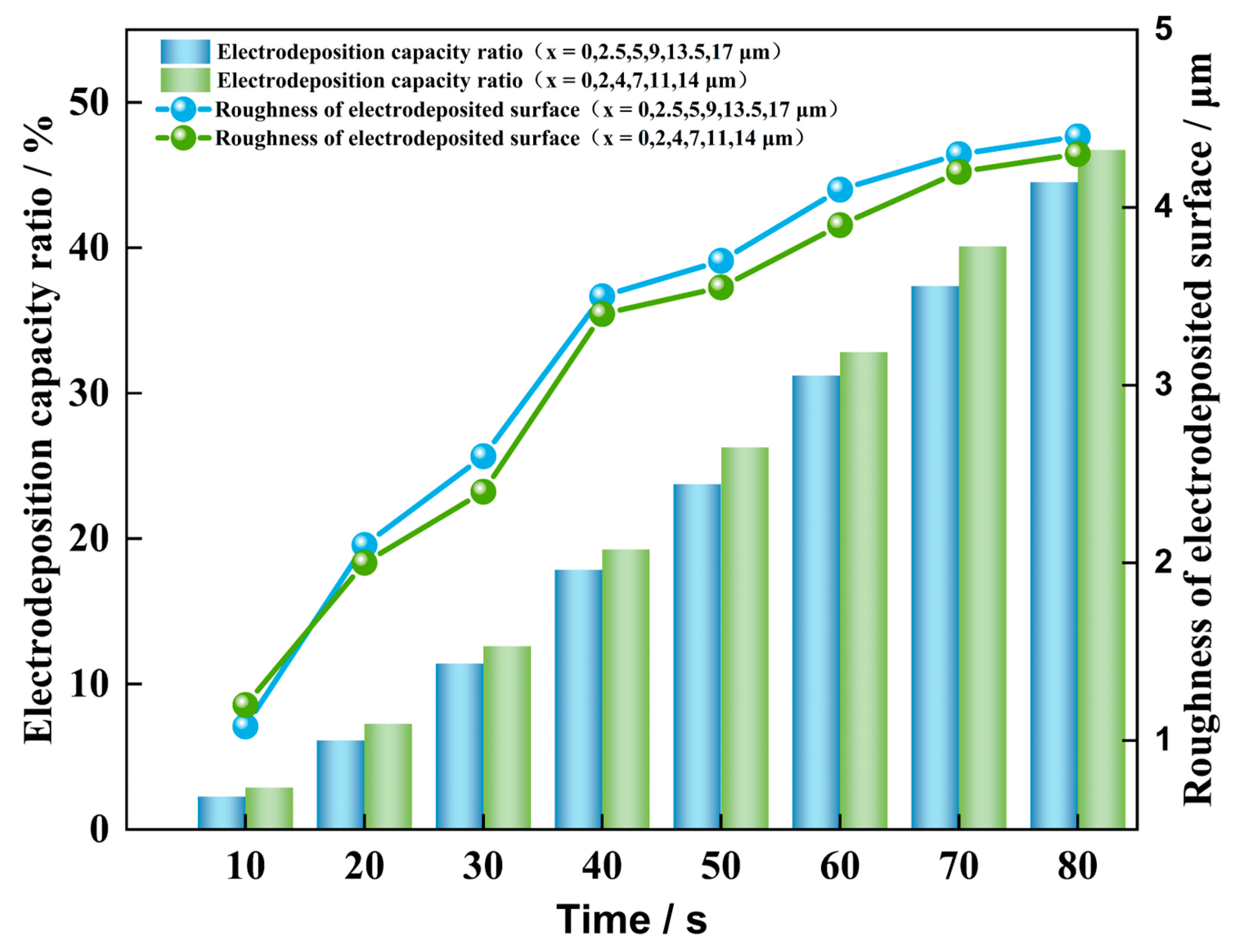
In the battery’s actual charging and discharging process, negative dendrite growth nucleation points randomly occur. The Unifrnd function can generate equal possible random numbers in the nucleation interval. Therefore, in this study, two sets of random nucleation points are generated for analysis using the Unifrnd function at 0, 2.5, 5, 9, 3.5, and 17 μm as well as 0, 2, 4, 7, 11, and 14 μm from the origin (Figure A1 and Figure A2). Compared with the first group of random nucleation sites, the second one has a smaller initial nucleation spacing. Figure A3 shows the lithium metal deposition capacity of the two random nucleation sites versus deposition surface roughness. It can be seen that when the charging time increases, the negative surface with smaller initial nucleation spacing has minor surface roughness and more compact dendrite growth, which is consistent with the above conclusion.

4.3. Influence of the Surface Energy Anisotropy Intensity on the Morphology of the Dendrite Growth

Surface energy is a vital driving force in the lithium deposition process, of which anisotropic intensity δ is an important parameter. The surface energy intensity in different dendrite growth directions reflects the growth preferences of the dendrites and growth differences in each order. It has been demonstrated [35,36] that the content of Cu in the alloy affects the anisotropy of the material interface. In addition, when the Cu content (mass fraction) decreases, the tendency of the arrangement of the aggregated phases in the alloy diminishes, which results in increasing the elongation and decreasing the anisotropic strength of the interface. Consequently, in this paper, four Cu-Zn alloy meshes with different contents (Cu 65%, Zn 35%; Cu 80%, Zn 20%; Cu 90%, Zn 10%; pure copper mesh) were selected for lithium metal plating to validate the simulation results, as shown in Figure 4f–m. Figure 4a–e show the shape of lithium dendrite growth at 80 s of charging with different values of surface energy anisotropy intensity (δ). It can be seen that the lithium dendrite formation significantly differs under different values of δ. When δ = 0, the growth morphology of lithium dendrites has a mossy structure [37,38], which shows uniform growth in all directions with no tendency in the growth direction, and the growth rate of dendrites is slow. The surface of the negative electrode after charging is relatively flat with low surface roughness, which is consistent with the experimental results shown in Figure 4f,j. When δ = 0.02, the morphology of the main branch is gradually formed, and the side branches grow around the main branch. When δ = 0.11, more nucleation sites are produced on the surface of the main branch [37,38], accompanied by more lateral branch growth, and the dendrite morphology has a shrub-like structure, which is consistent with the experimental results shown in Figure 4g,k. When δ = 0.15, the primary branch growth is more pronounced, the number of lateral branches is reduced, the dendrite becomes sharper, and the dendrite morphology has a rod-like structure [37,38], which is consistent with the experimental results shown in Figure 4h,l. When δ increases, the interfacial energy increases, and the more considerable interfacial energy can drive the rapid growth of the dendrite tip. When δ increases to 0.17, the interfacial instability increases, the main branch tips become increasingly sharp, and the splitting of the main branches accompanies them. The rod-like main branches split into more slender linear side branches, which is consistent with the experimental results shown in Figure 4i,m. These results demonstrate that lower interfacial energy anisotropy strength can slow down the dendrite tip growth. Consequently, subsequent interfacial electrochemical driving force experiments were conducted based on a Cu-Zn alloy network (65% Cu, 35% Zn).

4.4. Influence of the Interfacial Electrochemical Driving Force on the Dendrite Growth

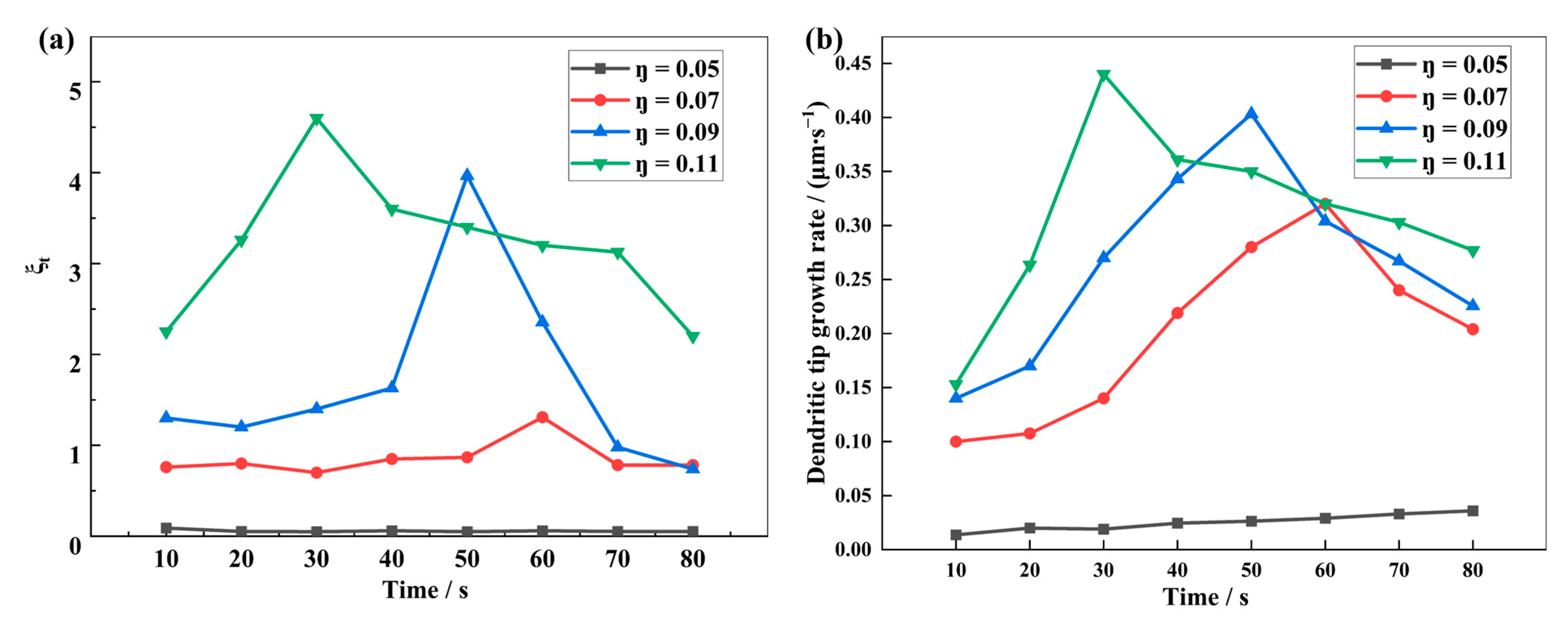
The formation of a new phase is always associated with a “deviation from equilibrium”. Therefore, the lithium metal deposition on the electrode surface is always accompanied by a deviation of the electrode from the equilibrium potential. The magnitude of this deviation is defined as the interfacial electrochemical (reaction) driving force [33], which is expressed by ŋ in the phase field equation (Equation (1)). To investigate the effect of the interfacial electrochemical driving force on the dendrite growth, a larger initial nucleation spacing d = 3.5 μm was chosen as shown in Figure 5. The simulation results show that the dendrite height gradually increases. The number of side branches develops more when the electrochemical driving force ŋ gradually increases from 0.05 to 0.11, and the spacing between two adjacent dendrites decreases. As the side branches of two adjacent dendrites begin to come into contact, a regional barrier of lithium metal deposition channels is created, and the dendrites eventually shift from a divergent growth pattern to a vertical growth pattern, as shown in Figure 5b–d. Figure 6a,b show the changes in lithium dendrite/electrolyte interfacial reaction current I (I∝ξt) and tip growth rate under different interfacial electrochemical driving forces. It can be seen that the lithium dendrite reaches the peak of interfacial reaction current and growth rate at 60, 50, and 30 s for interfacial electrochemical driving forces of 0.07, 0.09, and 0.11, respectively, showing an overall increase and then decrease. The larger the interfacial electrochemical driving force, the stronger the interfacial reaction current of the dendrite, the faster the electrochemical reaction rate, and therefore the faster the dendrite growth rate, the shorter the time for the dendrite to form a deposition barrier and for the current to reach its peak, and the shorter the time for the growth rate to reach its peak [24,39,40].
In the range of 40 s < t < 60 s, the peak current and growth rate of the dendrite at the interfacial electrochemical driving force of 0.09 are larger than those at the interfacial electrochemical driving force of 0.11, indicating that the electrochemical driving force does not control the current at this time. When the interdendritic deposition barrier is formed, the lithium metal deposition rate is governed by the lithium-ion transfer from the top liquid phase due to the space limitation and reduced lithium-ion receiving area [41,42,43]. On contrast, at an electrochemical driving force of 0.05, the dendrite growth did not show a significant deposition barrier for lithium metal, showing smaller current and growth rate fluctuations. One possibility for the differences in dendrite morphology at different interfacial electrochemical driving forces is related to the quantization of the length-to-height ratio of dendrite side branch growth. The greater the quantization of this ratio, the less the electrochemical driving force and the easier it is to form a slender dendrite morphology and, conversely, a dendrite with side branches [22].
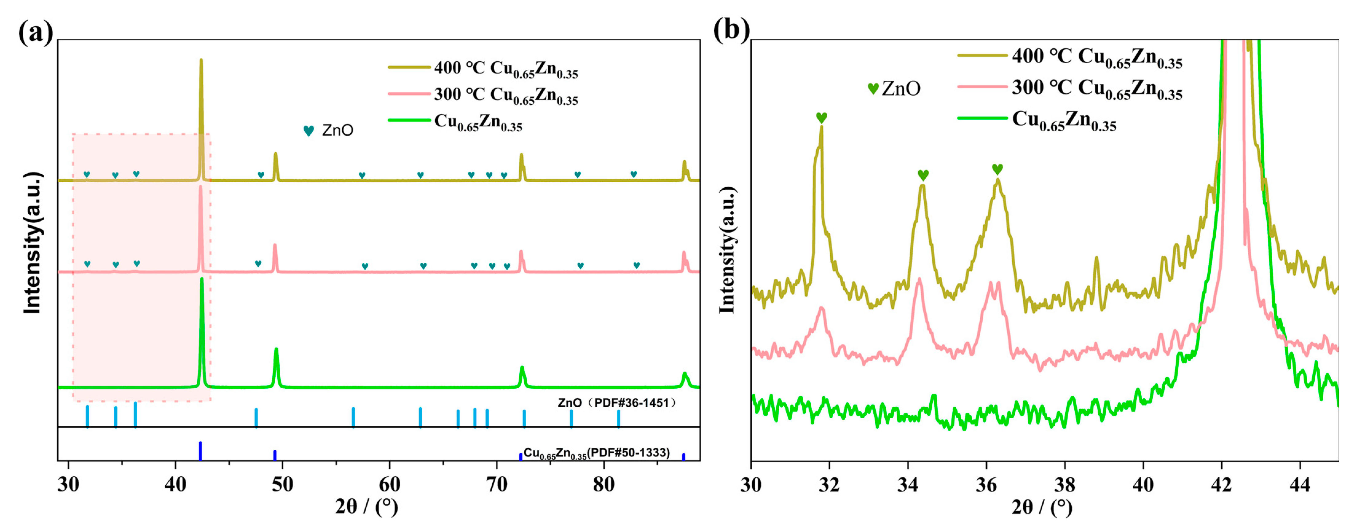
To some extent, the nucleation overpotential of lithium affects the magnitude of the interfacial electrochemical driving force, and a high overpotential can provide a greater driving force for nucleation. Compared with the Cu-Zn alloy mesh collector after heat treatment at 300 °C (Figure 7a), the surface of the Cu-Zn alloy mesh collector after heat treatment at 400 °C is covered with a large amount of nano-flocculent (Figure 7b). The two samples were analyzed by X-ray powder diffraction (XRD) using an X-ray diffractometer, as shown in Figure 8. The three diffraction peaks of the unheated treated Cu-Zn alloy mesh fluid XRD pattern were located at 42.324°, 49.274°and 72.243°, corresponding to Cu0.65Zn0.35 alloy (PDF#50-1333). The three diffraction peaks at 31.769°, 34.421°, and 36.252° for the collector fluid after heat treatment at 300 °C and 400 °C correspond to ZnO (PDF#36-1451), indicating that the flocs produced on the surface of the collector fluid of the Cu-Zn alloy network are metal oxides ZnO [44].
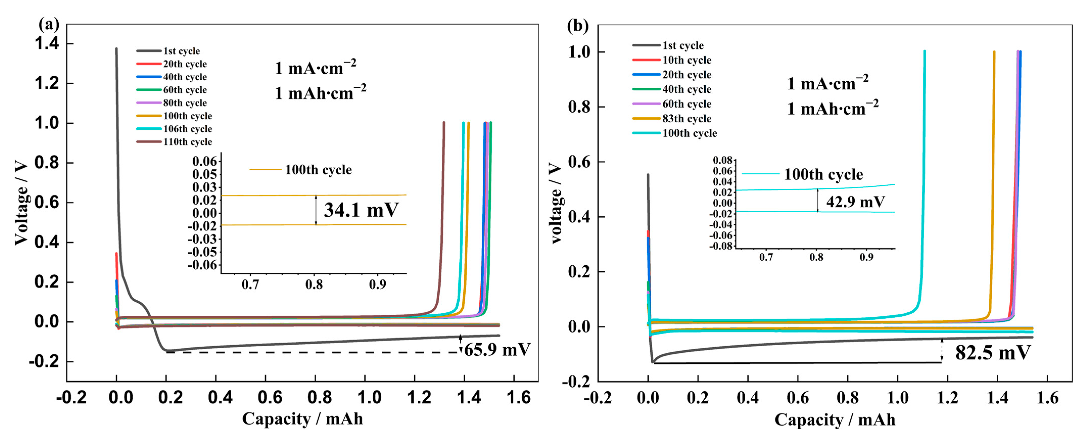
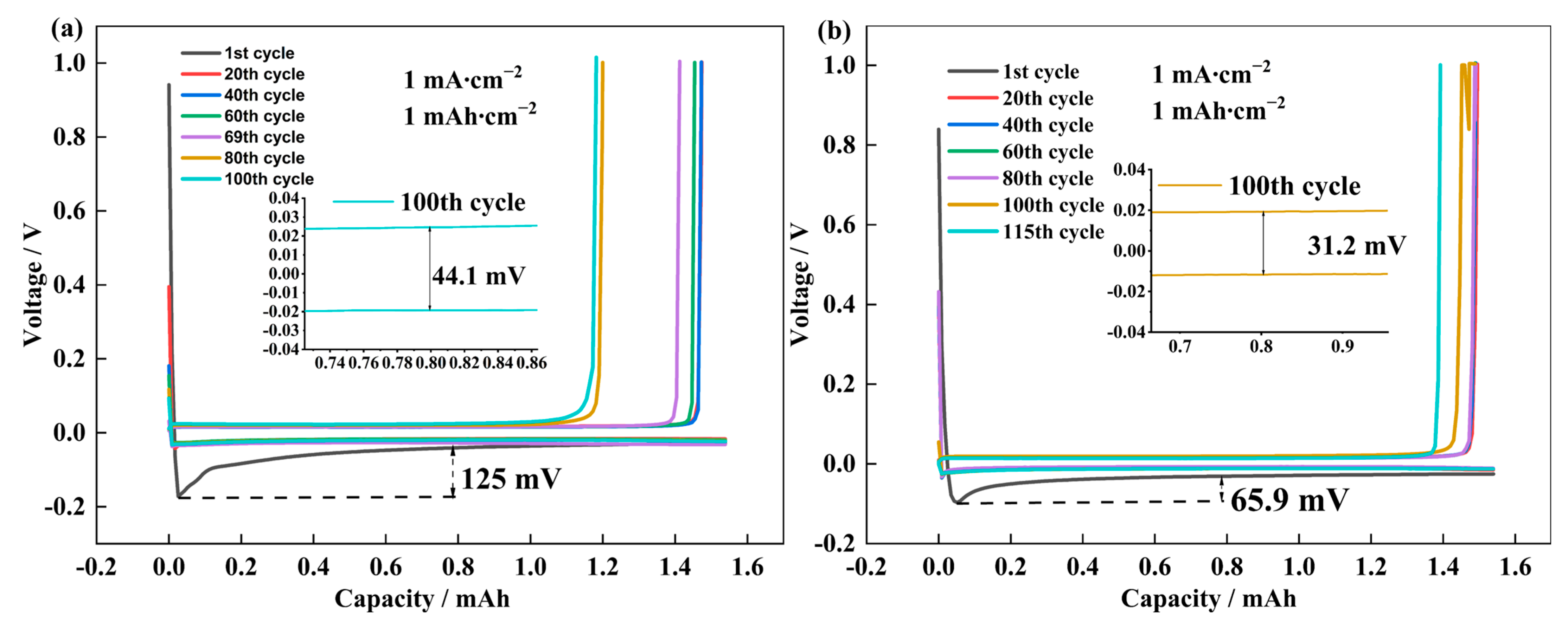
The half-cells were assembled with the Cu-Zn alloy mesh collector as the negative electrode after heat treatment at 300 °C and 400 °C. The half-cell charging and discharging curves are shown in Figure 9a,b, and the nucleation overpotentials were 125.0 mV and 65.9 mV, respectively. At the nucleation overpotential of 125.0 mV, the lithium dendrite growth shape is biased toward shrub and dendrite (Figure 10a), which is consistent with the simulation results in Figure 5b–d. At the nucleation overpotential of 65.9 mV, lithium metal deposition tends to have a long nodular structure (Figure 10b), which is consistent with the simulation results (Figure 5a). This indicates that the nucleation overpotential can affect the interfacial electrochemical driving force and, thus, the deposition morphology of lithium metal. A larger interfacial electrochemical driving force can cause the lithium dendrites to grow in all directions and exhibit shrub-like or dendritic shapes. The formation of a lithium-friendly ZnO layer on the surface of the collector fluid may cause these two deposition morphology differences. It has been reported [1] that a surface ZnO layer with a lithium-friendly effect can reduce the local current density and nucleation overpotential, thus reducing the interfacial electrochemical driving force, promoting the uniform deposition of lithium metal, and retarding the dendrite growth. Charge/discharge curves of Cu-Zn alloy mesh at 350 °C and 450 °C with SEM images of heat treatment and the deposited surface are supplemented in Figure A4, Figure A5 and Figure A6. Compared with the alloy mesh heat-treated at 350 °C (sparse flocs formed on the surface shown in Figure A5a) and 400 °C (relatively uniform flocs formed on the surface shown in Figure 7b), the alloy mesh heat-treated at 450 °C forms more densely, non-directional and convergent feather-like flocs on the surface shown in Figure A5b. According to the heterogeneous nucleation model [45,46], there is an increase in the overpotential of lithium metal nucleation(Figure A4b) due to the inhomogeneity of the interface, which will lead to an increase in the interfacial driving force and promotes the growth of lithium dendrites, producing a poorer deposition interface(Figure A6b).
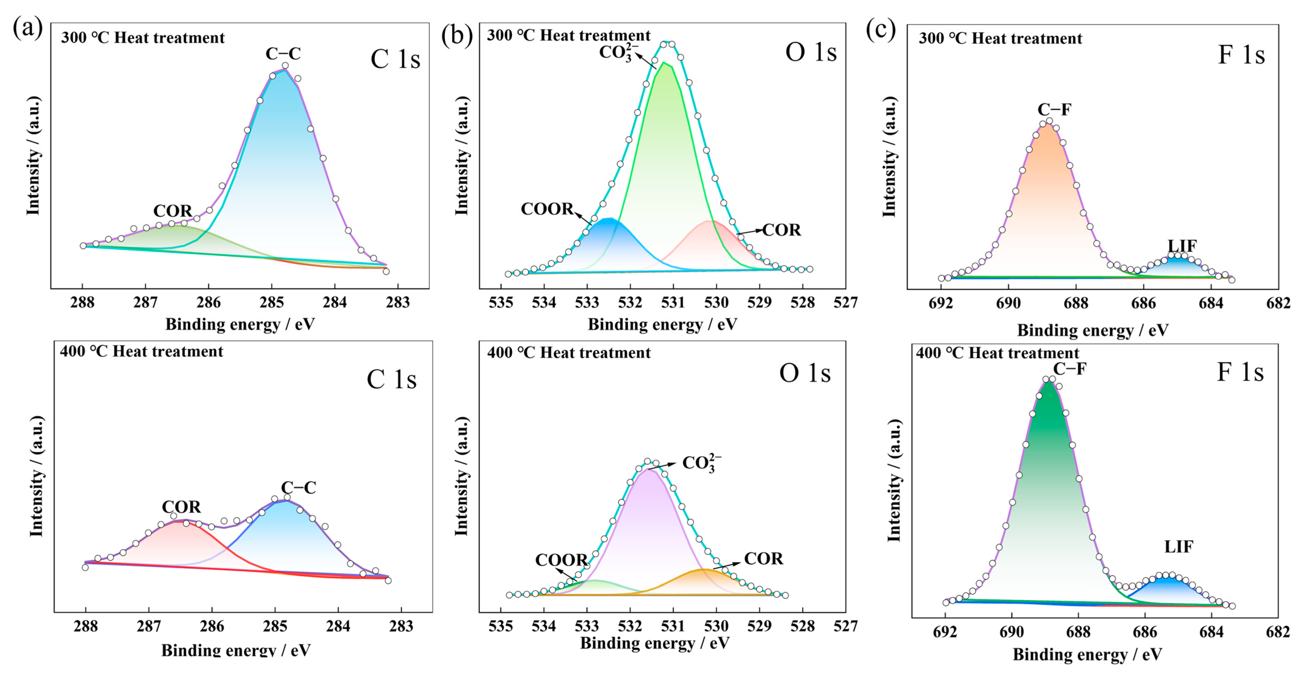
Moreover, the charging and discharging curves (Figure 9a,b) show that the charging capacity of the half-cell with the Cu-Zn alloy mesh collector as the negative electrode after heat treatment at 300 °C is 1.1553 mAh after 100 cycles, and the Coulomb efficiency is 75.1% (with discharging capacity of 1.539 mAh). In contrast, 400 °C had a charge capacity of 1.4717 mAh and a coulomb efficiency of 95.7% (discharge capacity of 1.539 mAh) after 100 cycles. The reasons for the difference in coulometric efficiency between the two samples are twofold. On the one hand, a stable lithium/electrolyte interface prevents corrosion of the lithium metal by the electrolyte, improves the Coulomb efficiency and promotes homogeneous plating/exfoliation of the lithium metal [47]. X-ray photoelectron spectroscopy (XPS) analysis was further performed on the lithium metal negative electrode of the half-cell after cycles. Figure 11 shows the XPS pattern analysis of the half-cell’s lithium metal negative electrode surface with the Cu-Zn alloy mesh as electrode heat-treated at 300 °C and 400 °C. It can be seen from the C 1s pattern that the peaks at 284.8 eV and 286.4 eV, respectively, belong to C-C and COR, and these mainly originate from the by-products of the organic electrolyte [48,49,50]. In the O 1s pattern, the peaks at 530.2, 531.4, and 532.6 eV correspond to COR, C O 3 2 , and COOR [12], respectively. In the F 1s pattern, peaks appearing at 684.9 eV and 688.9 eV in two valence states are attributed to LiF and -CF3 functional groups in LiTFSI [51,52]. Therefore, the relatively low contents of decomposition products COR, C O 3 2 and COOR at the interface of the 400 °C heat-treated Cu-Zn alloy mesh indicates that the 400° heat-treated Cu-Zn alloy mesh as an electrode effectively reduces the side reactions at the lithium metal/electrolyte and improves the stability of the interface. At the same time, the deposited surface of the 400 °C heat-treated Cu-Zn alloy mesh as an electrode has a relatively high LiF content. Some studies [53] have confirmed that the high content of LiF on the lithium metal deposited surface can effectively improve the stability of the interfacial SEI film and inhibit the formation of lithium dendrites. As illustrated by the XPS data, the half-cell deposition interface assembled with a collector heat-treated at 400 °C has better stability compared to 300 °C. On the other hand, the shrub-like and dendritic dendrites have a larger specific surface area than the long nodular dendrites (Figure 5a–d). The growth of dendrites increases the exposed surface area of the negative electrode. The newly exposed lithium metal surface also reacts with the electrolyte, severely depletes the active material, and reduces the cell Coulomb efficiency.

5. Conclusions

This paper performed experiments and simulations to study the factors that affect the growth of lithium dendrites using a phasefield model. Different initial nucleation spacing, surface energy anisotropy strength, and interfacial electrochemical driving force on the lithium dendrite morphology were simulated. The obtained results can be summarized as follows:
(1)
A smaller initial nucleation spacing can reduce the surface roughness of the deposited lithium metal and inhibit dendrite growth. When the initial nucleation spacing is small, the lateral branching growth of the dendrites is inhibited. The lithium metal is mainly deposited at the tips of the dendrites, which results in a low surface roughness of the deposited negative electrode, and the shape of dendrite growth is flatter. When the initial nucleation spacing of the dendrites is larger, their lateral branching growth is more pronounced, and the shape of dendrite growth is more shrub-like or dendritic.
(2)
A lower interfacial energy anisotropy strength can slow down the growth of dendrite tips. At lower surface energy anisotropy intensity, the dendrites uniformly grow in all the orders with a mossy morphology. When the surface energy anisotropy intensity increases, the dendrites start to have the advantage of main branch growth, the more considerable interfacial energy makes their tips rapidly grow, and their shape appears shrub-like and rod-like. When the interfacial energy anisotropy intensity reaches a specific value, the main branches of rod-like dendrites also split into more slender linear side branches.
(3)
Reducing the nucleation overpotential results in a small interfacial electrochemical driving force and a low dendrite growth rate, which effectively suppresses dendrite growth. The dendrite interfacial reaction current and growth rate increase with the increase of the electrochemical driving force. At high nucleation overpotential, the higher the interfacial electrochemical driving force, the greater the apical dominance of dendrite growth and the more likely the formation of shrub-type dendrites. On the contrary, a lower nucleation overpotential and a lower interfacial electrochemical driving force can reduce the growth rate of lithium dendrites and make them more easily grow into thin and long dendrites.

Author Contributions

Conceptualization, Y.Y., K.Z. and Y.H.; Data curation, G.X. and N.Y.; Investigation, C.H. and Q.G.; Methodology, Y.C. and X.Y.; Software, Y.C.; Writing—Original draft, Y.C.; Writing—Review and editing, Y.C. and X.Y. All authors have read and agreed to the published version of the manuscript.

Funding

This work was funded by the National Natural Science Foundation of China (Grant Nos. 22168019 and 52074141).

Data Availability Statement

The data are not publicly available due to the research project in progress.

Conflicts of Interest

The authors declare no conflict of interest.

Appendix A

Figure A1. Morphology of dendrites at random nucleation spacing (x = 0, 2.5, 5, 9, 13.5, and 17 μm).
Energies 16 03745 g0a1
Figure A2. Morphology of dendrites at random nucleation spacing (x = 0, 2, 4, 7, 11, and 14 μm).
Energies 16 03745 g0a2
Figure A3. Electroplated surface roughness and lithium electroplating capacity under random nucleation intervals.
Energies 16 03745 g0a3
Figure A4. The half-cell charge-discharge curves of Cu-Zn alloy mesh after heat treatment. (a) Treatment at 350 °C; (b) Treatment at 450 °C.
Energies 16 03745 g0a4
Figure A5. SEM images of Cu-Zn alloy mesh surface after heat treatment at different temperatures. (a) 350 °C heat treatment; (b) 450 °C heat treatment.
Energies 16 03745 g0a5
Figure A6. SEM images of the surface of the Cu-Zn alloy mesh collector after 100 cycles of the cell. (a) Cu-Zn alloy mesh collector heat treated at 350 °C; (b) Cu-Zn alloy mesh collector heat treated at 450 °C.
Energies 16 03745 g0a6

References

  1. Jin, C.; Sheng, O.; Luo, J.; Yuan, H.; Fang, C.; Zhang, W.; Huang, H.; Gan, Y.; Xia, Y.; Liang, C.; et al. 3D lithium metal embedded within lithiophilic porous matrix for stable lithium metal batteries. Nano Energy 2017, 37, 177–186. [Google Scholar] [CrossRef]
  2. Cheng, X.B.; Hou, T.Z.; Zhang, R.; Peng, H.J.; Zhao, C.Z.; Huang, J.Q.; Zhang, Q. Dendrite-Free Lithium Deposition Induced by Uniformly Distributed Lithium Ions for Efficient Lithium Metal Batteries. Adv. Mater. 2016, 28, 2888–2895. [Google Scholar] [CrossRef] [PubMed]
  3. Yamada, Y.; Yamada, A. Review—Superconcentrated Electrolytes for Lithium Batteries. J. Electrochem. Soc. 2015, 162, A2406–A2423. [Google Scholar] [CrossRef]
  4. Jeong, S.-K.; Seo, H.-Y.; Kim, D.-H.; Han, H.-K.; Kim, J.-G.; Lee, Y.B.; Iriyama, Y.; Abe, T.; Ogumi, Z. Suppression of dendritic lithium formation by using concentrated electrolyte solutions. Electrochem. Commun. 2008, 10, 635–638. [Google Scholar] [CrossRef]
  5. Camacho-Forero, L.E.; Smith, T.W.; Balbuena, P.B. Effects of High and Low Salt Concentration in Electrolytes at Lithium–Metal Anode Surfaces. J. Phys. Chem. C 2016, 121, 182–194. [Google Scholar] [CrossRef]
  6. Chen, X.; Hou, T.-Z.; Li, B.; Yan, C.; Zhu, L.; Guan, C.; Cheng, X.-B.; Peng, H.-J.; Huang, J.-Q.; Zhang, Q. Towards stable lithium-sulfur batteries: Mechanistic insights into electrolyte decomposition on lithium metal anode. Energy Storage Mater. 2017, 8, 194–201. [Google Scholar] [CrossRef]
  7. Xu, K. Nonaqueous liquid electrolytes for lithium-based rechargeable batteries. Chem. Rev. 2004, 104, 4303–4417. [Google Scholar] [CrossRef]
  8. Kuwata, H.; Sonoki, H.; Matsui, M.; Matsuda, Y.; Imanishi, N. Surface Layer and Morphology of Lithium Metal Electrodes. Electrochemistry 2016, 84, 854–860. [Google Scholar] [CrossRef]
  9. Heine, J.; Hilbig, P.; Qi, X.; Niehoff, P.; Winter, M.; Bieker, P. Fluoroethylene Carbonate as Electrolyte Additive in Tetraethylene Glycol Dimethyl Ether Based Electrolytes for Application in Lithium Ion and Lithium Metal Batteries. J. Electrochem. Soc. 2015, 162, A1094–A1101. [Google Scholar] [CrossRef]
  10. Ding, F.; Xu, W.; Graff, G.L.; Zhang, J.; Sushko, M.L.; Chen, X.; Shao, Y.; Engelhard, M.H.; Nie, Z.; Xiao, J.; et al. Dendrite-free lithium deposition via self-healing electrostatic shield mechanism. J. Am. Chem. Soc. 2013, 135, 4450–4456. [Google Scholar] [CrossRef]
  11. Kim, H.J.; Umirov, N.; Park, J.-S.; Lim, J.-H.; Zhu, J.; Kim, S.-S.; Myung, S.-T. Lithium dendritic growth inhibitor enabling high capacity, dendrite-free, and high current operation for rechargeable lithium batteries. Energy Storage Mater. 2022, 46, 76–89. [Google Scholar] [CrossRef]
  12. Ye, H.; Yin, Y.-X.; Zhang, S.-F.; Shi, Y.; Liu, L.; Zeng, X.-X.; Wen, R.; Guo, Y.-G.; Wan, L.-J. Synergism of Al-containing solid electrolyte interphase layer and Al-based colloidal particles for stable lithium anode. Nano Energy 2017, 36, 411–417. [Google Scholar] [CrossRef]
  13. Basile, A.; Bhatt, A.I.; O’Mullane, A.P. Stabilizing lithium metal using ionic liquids for long-lived batteries. Nat. Commun. 2016, 7, ncomms11794. [Google Scholar] [CrossRef]
  14. Xu, X.-Q.; Jiang, F.-N.; Yang, S.-J.; Xiao, Y.; Liu, H.; Liu, F.; Liu, L.; Cheng, X.-B. Dual-layer vermiculite nanosheet based hybrid film to suppress dendrite growth in lithium metal batteries. J. Energy Chem. 2022, 69, 205–210. [Google Scholar] [CrossRef]
  15. Tu, Z.; Zachman, M.J.; Choudhury, S.; Wei, S.; Ma, L.; Yang, Y.; Kourkoutis, L.F.; Archer, L.A. Nanoporous Hybrid Electrolytes for High-Energy Batteries Based on Reactive Metal Anodes. Adv. Energy Mater. 2017, 7, 1602367. [Google Scholar] [CrossRef]
  16. Tikekar, M.D.; Archer, L.A.; Koch, D.L. Stabilizing electrodeposition in elastic solid electrolytes containing immobilized anions. Sci. Adv. 2016, 2, e1600320. [Google Scholar] [CrossRef]
  17. Jia, M.; Zhao, N.; Huo, H.; Guo, X. Comprehensive Investigation into Garnet Electrolytes Toward Application-Oriented Solid Lithium Batteries. Electrochem. Energy Rev. 2020, 3, 656–689. [Google Scholar] [CrossRef]
  18. Chen, Y.; Jiang, Y.; Chi, S.-S.; Woo, H.J.; Yu, K.; Ma, J.; Wang, J.; Wang, C.; Deng, Y. Understanding the lithium dendrites growth in garnet-based solid-state lithium metal batteries. J. Power Sources 2022, 521, 230921. [Google Scholar] [CrossRef]
  19. Monroe, C.; Newman, J. Dendrite Growth in Lithium/Polymer Systems. J. Electrochem. Soc. 2003, 150, A1377. [Google Scholar] [CrossRef]
  20. Liang, L.; Qi, Y.; Xue, F.; Bhattacharya, S.; Harris, S.J.; Chen, L.Q. Nonlinear phase-field model for electrode-electrolyte interface evolution. Phys. Rev. E Stat. Nonlinear Soft Matter Phys. 2012, 86, 051609. [Google Scholar] [CrossRef]
  21. Ely, D.R.; Jana, A.; García, R.E. Phase field kinetics of lithium electrodeposits. J. Power Sources 2014, 272, 581–594. [Google Scholar] [CrossRef]
  22. Chen, L.; Zhang, H.W.; Liang, L.Y.; Liu, Z.; Qi, Y.; Lu, P.; Chen, J.; Chen, L.-Q. Modulation of dendritic patterns during electrodeposition: A nonlinear phase-field model. J. Power Sources 2015, 300, 376–385. [Google Scholar] [CrossRef]
  23. Vu, T.T.; Eom, G.H.; Lee, J.; Park, M.-S.; Moon, J. Electrolyte interface design for regulating Li dendrite growth in rechargeable Li-metal batteries: A theoretical study. J. Power Sources 2021, 496, 229791. [Google Scholar] [CrossRef]
  24. Lee, H.; Kwak, T.; Lee, W.; Song, J.; Kim, D. Effect of surface topography on dendritic growth in lithium metal batteries. J. Power Sources 2022, 552, 232264. [Google Scholar] [CrossRef]
  25. Chen, C.-H.; Pao, C.-W. Phase-field study of dendritic morphology in lithium metal batteries. J. Power Sources 2021, 484, 229203. [Google Scholar] [CrossRef]
  26. Gao, L.; Guo, Z. Phase-field simulation of Li dendrites with multiple parameters influence. Comput. Mater. Sci. 2020, 183, 109919. [Google Scholar] [CrossRef]
  27. Yan, H.H.; Bie, Y.H.; Cui, X.Y.; Xiong, G.P.; Chen, L. A computational investigation of thermal effect on lithium dendrite growth. Energy Convers. Manag. 2018, 161, 193–204. [Google Scholar] [CrossRef]
  28. Yurkiv, V.; Foroozan, T.; Ramasubramanian, A.; Shahbazian-Yassar, R.; Mashayek, F. The influence of stress field on Li electrodeposition in Li-metal battery. MRS Commun. 2018, 8, 1285–1291. [Google Scholar] [CrossRef]
  29. Tan, J.; Tartakovsky, A.M.; Ferris, K.; Ryan, E.M. Investigating the Effects of Anisotropic Mass Transport on Dendrite Growth in High Energy Density Lithium Batteries. J. Electrochem. Soc. 2015, 163, A318–A327. [Google Scholar] [CrossRef]
  30. Mu, W.; Liu, X.; Wen, Z.; Liu, L. Numerical simulation of the factors affecting the growth of lithium dendrites. J. Energy Storage 2019, 26, 100921. [Google Scholar] [CrossRef]
  31. Allen, S.M.; Cahn, J.W. Ground state structures in ordered binary alloys with second neighbor interactions. Acta Metall. 1972, 20, 423–433. [Google Scholar] [CrossRef]
  32. Kodým, R.; Šnita, D.; Bouzek, K. Mathematical Modeling of Electromembrane Processes. In Current Trends and Future Developments on (Bio-) Membranes; Elsevier: Turin, Italy, 2019; pp. 285–326. [Google Scholar]
  33. Zha, C.X. Introduction to Electrode Process Dynamics, 3rd ed.; Science Press: Beijing, China, 2002; pp. 129–146. [Google Scholar]
  34. Tu, Z.; Nath, P.; Lu, Y.; Tikekar, M.D.; Archer, L.A. Nanostructured electrolytes for stable lithium electrodeposition in secondary batteries. Acc. Chem. Res. 2015, 48, 2947–2956. [Google Scholar] [CrossRef] [PubMed]
  35. Stephens, A.W. Texture and Mechanical Anisotropy in the Copper-zinc System; The University of Arizona: Tucson, AZ, USA, 1968. [Google Scholar]
  36. Yu, F.; Xu, D.; Chen, S.; Chen, K.; Wang, X.; Liu, D.; Ma, Y.; Huang, C.; Yan, D. Effect of Cu Content on Anisotropy of Mechanical Property of Al-Cu-Mn Alloy. Chin. J. Mater. Res. 2018, 32, 853–860. [Google Scholar] [CrossRef]
  37. Becherer, J.; Kramer, D.; Mönig, R. The growth mechanism of lithium dendrites and its coupling to mechanical stress. J. Mater. Chem. A 2022, 10, 5530–5539. [Google Scholar] [CrossRef]
  38. Steiger, J.; Kramer, D.; Mönig, R. Microscopic observations of the formation, growth and shrinkage of lithium moss during electrodeposition and dissolution. Electrochim. Acta 2014, 136, 529–536. [Google Scholar] [CrossRef]
  39. Jackle, M.; Gross, A. Microscopic properties of lithium, sodium, and magnesium battery anode materials related to possible dendrite growth. J. Chem. Phys. 2014, 141, 174710. [Google Scholar] [CrossRef]
  40. Zhang, H.-W.; Liu, Z.; Liang, L.; Chen, L.; Qi, Y.; Harris, S.J.; Lu, P.; Chen, L.-Q. Understanding and Predicting the Lithium Dendrite Formation in Li-Ion Batteries: Phase Field Model. ECS Trans. 2014, 61, 1. [Google Scholar] [CrossRef]
  41. Zhang, R.; Shen, X.; Cheng, X.-B.; Zhang, Q. The dendrite growth in 3D structured lithium metal anodes: Electron or ion transfer limitation? Energy Storage Mater. 2019, 23, 556–565. [Google Scholar] [CrossRef]
  42. Ans, M.; Atif Makhdoom, M.; Faisal Irfan, M.; Al Abir, A. Optimized modelling and kinetic analysis of nickel recovery from waste orthodontic implants using response surface methodology. Miner. Eng. 2022, 175, 107279. [Google Scholar] [CrossRef]
  43. Yurkiv, V.; Foroozan, T.; Ramasubramanian, A.; Shahbazian-Yassar, R.; Mashayek, F. Phase-field modeling of solid electrolyte interface (SEI) influence on Li dendritic behavior. Electrochim. Acta 2018, 265, 609–619. [Google Scholar] [CrossRef]
  44. Hadef, F.; Ans, M. X-ray analysis and Rietveld refinement of ball milled Fe50Al35Ni15 powder. Surf. Interfaces 2021, 26, 101303. [Google Scholar] [CrossRef]
  45. Meng, Q.; Deng, B.; Zhang, H.; Wang, B.; Zhang, W.; Wen, Y.; Ming, H.; Zhu, X.; Guan, Y.; Xiang, Y.; et al. Heterogeneous nucleation and growth of electrodeposited lithium metal on the basal plane of single-layer graphene. Energy Storage Mater. 2019, 16, 419–425. [Google Scholar] [CrossRef]
  46. Cheng, X.B.; Zhang, R.; Zhao, C.Z.; Zhang, Q. Toward Safe Lithium Metal Anode in Rechargeable Batteries: A Review. Chem. Rev. 2017, 117, 10403–10473. [Google Scholar] [CrossRef]
  47. Qian, J.; Henderson, W.A.; Xu, W.; Bhattacharya, P.; Engelhard, M.; Borodin, O.; Zhang, J.G. High rate and stable cycling of lithium metal anode. Nat. Commun. 2015, 6, 6362. [Google Scholar] [CrossRef]
  48. Li, N.W.; Yin, Y.X.; Li, J.Y.; Zhang, C.H.; Guo, Y.G. Passivation of Lithium Metal Anode via Hybrid Ionic Liquid Electrolyte toward Stable Li Plating/Stripping. Adv. Sci. 2017, 4, 1600400. [Google Scholar] [CrossRef]
  49. Busche, M.R.; Drossel, T.; Leichtweiss, T.; Weber, D.A.; Falk, M.; Schneider, M.; Reich, M.L.; Sommer, H.; Adelhelm, P.; Janek, J. Dynamic formation of a solid-liquid electrolyte interphase and its consequences for hybrid-battery concepts. Nat. Chem. 2016, 8, 426–434. [Google Scholar] [CrossRef]
  50. Muhammad, A.; Sales, W.F. Iron-graphene based anode material for rechargeable lithium-ion batteries decorated by gold nanoparticles recovered from gold plated waste surgical tools. Surf. Interfaces 2021, 27, 101575. [Google Scholar] [CrossRef]
  51. Zhang, X.-Q.; Cheng, X.-B.; Chen, X.; Yan, C.; Zhang, Q. Fluoroethylene Carbonate Additives to Render Uniform Li Deposits in Lithium Metal Batteries. Adv. Funct. Mater. 2017, 27, 1605989. [Google Scholar] [CrossRef]
  52. Liu, F.; Xiao, Q.; Wu, H.B.; Shen, L.; Xu, D.; Cai, M.; Lu, Y. Fabrication of Hybrid Silicate Coatings by a Simple Vapor Deposition Method for Lithium Metal Anodes. Adv. Energy Mater. 2018, 8, 1701744. [Google Scholar] [CrossRef]
  53. Cao, X.; Ren, X.; Zou, L.; Engelhard, M.H.; Huang, W.; Wang, H.; Matthews, B.E.; Lee, H.; Niu, C.; Arey, B.W.; et al. Monolithic solid–electrolyte interphases formed in fluorinated orthoformate-based electrolytes minimize Li depletion and pulverization. Nat. Energy 2019, 4, 796–805. [Google Scholar] [CrossRef]
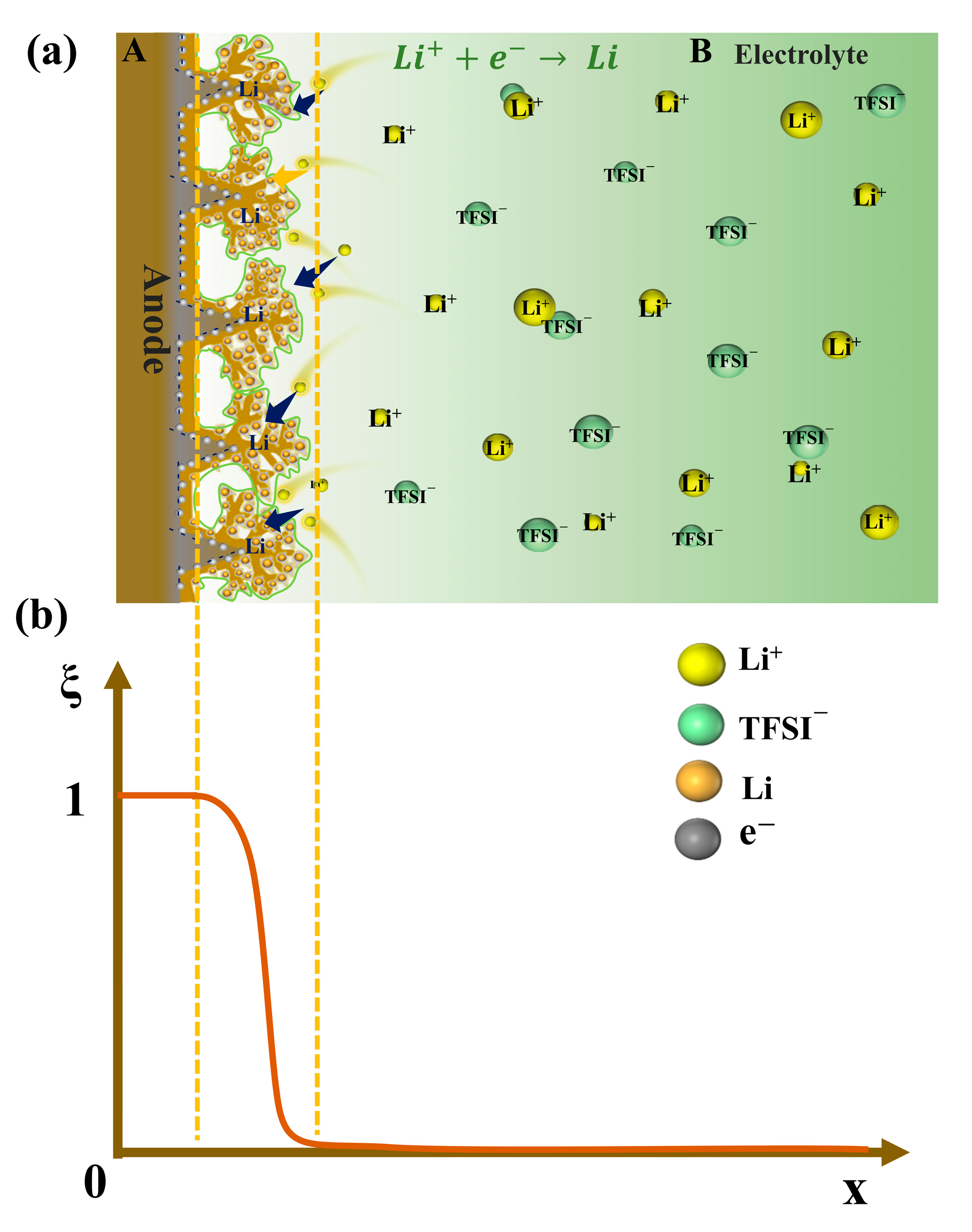
Figure 1. Schematic diagram of the dendrite growth mechanism and phase field variable ξ. (a) Dendrite growth mechanism; (b) The varies of phasefield variable ξ.
Energies 16 03745 g001
Figure 2. Simulation results and surface morphology of lithium dendrite growth. (a) Morphology of lithium dendrites; (b) Changes in Li-ion concentration; (c) Changes in electric potential; (d,e) SEM images of anode surface of Li metal battery; (f) Variation of dendrite height.
Energies 16 03745 g002
Figure 3. Variation of lithium dendrite growth, Li metal deposition capacity, and deposition surface roughness with time for different initial nucleation spacing. (a) Li-ion concentration; (b) Lithium dendrite morphology; (c) Lithium dendrite profile; (d) Li metal deposition capacity and deposition surface roughness variation.
Energies 16 03745 g003
Figure 4. The morphology of lithium dendrites with different anisotropy strengths. (ae) Simulation of dendrite morphology; (fm) SEM images of dendrites under Cu-Zn alloy mesh with different copper content.
Energies 16 03745 g004
Figure 5. Dendrite growth morphology simulation by Comsol under a variety of electrochemical driving forces at 80 s. (a) ŋ = 0.05; (b) ŋ = 0.07; (c) ŋ = 0.09; (d) ŋ = 0.11.
Energies 16 03745 g005
Figure 6. Variation of dendrite growth under different interfacial electrochemical driving forces. (a) Variation of ξt; (b) Variation of dendrite tip growth velocity.
Energies 16 03745 g006
Figure 7. SEM images of Cu-Zn alloy mesh surface after heat treatment at different temperatures. (a) 300 °C heat treatment; (b) 400 °C heat treatment.
Energies 16 03745 g007
Figure 8. XRD patterns of Cu-Zn alloy mesh after heat treatment. (a) Global image of XRD; (b) Local enlargement image of XRD.
Energies 16 03745 g008
Figure 9. The half-cell charge-discharge curves of Cu-Zn alloy mesh after heat treatment. (a) The half-cell charge-discharge curves of Cu-Zn alloy mesh collector after treatment at 300 °C; (b) The half-cell charge-discharge curves of Cu-Zn alloy mesh collector after treatment at 400 °C.
Energies 16 03745 g009
Figure 10. SEM images of the surface of the Cu-Zn alloy mesh collector after 100 cycles of the cell. (a) Cu-Zn alloy mesh collector heat treated at 300 °C; (b) Cu-Zn alloy mesh collector heat treated at 400 °C.
Energies 16 03745 g010
Figure 11. XPS pattern analysis of the half-cell’s lithium metal negative electrode surface with the Cu-Zn alloy mesh as electrode heat-treated at 300 and 400 °C. (a) C 1s; (b) O 1s; (c) F 1s.
Energies 16 03745 g011
Table 1. Relevant physical parameters.
ParameterSymbolValueReferences
Anisotropic modulus w 4[22]
Diffusion coefficient in solution D s / m 2 · s 1 0.2 × 10⁻¹⁴ [33]
Diffusion Coefficient in Electrodes D e / m 2 · s 1 1 × 10⁻¹⁴ [33]
Symmetric factor α 0.5[22]
Reaction constant L η / s 1[22]
Gradient energy coefficient k 0 / J · m 1 5 × 10⁻¹⁰ [22,33]
Interfacial mobility L σ / m 3 · ( J · s ) 1 2.5 × 10⁻⁶ [22]
Faraday constant F / C · m o l 1 9.65 × 10⁴[30,34]
Barrier height W / J · m 3 3.5 × 10⁵ [22]
Gas constant R / J · ( m o l · K ) 1 8.314[30]
Conductivity in electrode σ e / S · m 1 1 × 10⁷-
Disclaimer/Publisher’s Note: The statements, opinions and data contained in all publications are solely those of the individual author(s) and contributor(s) and not of MDPI and/or the editor(s). MDPI and/or the editor(s) disclaim responsibility for any injury to people or property resulting from any ideas, methods, instructions or products referred to in the content.