Article

Investigation of Transcritical Carbon Dioxide Power Generation System Based on Vortex Tube

State Key Laboratory of Eco-Hydraulics in Northwest Arid Region of China, Xi’an University of Technology, Xi’an 710048, China
*
Author to whom correspondence should be addressed.
Energies 2023, 16(9), 3723; https://doi.org/10.3390/en16093723
Submission received: 24 February 2023 / Revised: 20 April 2023 / Accepted: 24 April 2023 / Published: 26 April 2023

Abstract

:
In this paper, a transcritical carbon dioxide power generation system based on a vortex tube is studied, which has the advantage of the self-condensation of carbon dioxide. The thermodynamic performance of the system was investigated by establishing a mathematical model. The results showed that under fundamental working conditions, the system could output a net power of 271.72 kW, and the thermal efficiency as well as the exergy efficiency of the system could reach 7.38% and 27.09%, respectively. Exergy analysis showed that the turbine had the greatest exergy loss among the system’s components, followed by the vortex tube, pump, heater and cooler. Parameter analysis showed that increasing the outlet pressure and inlet temperature of the vortex tube can improve the thermal efficiency and exergy efficiency of the system. In addition, the improvement in the turbine component’s efficiency is the most beneficial to the system’s performance, among which the turbine’s efficiency has the greatest impact. Carbon dioxide can be effectively liquified by expanding it in the vortex tube, and its liquefaction ratio increases with the decrease in the vortex tube’s inlet temperature and the increase in the vortex tube’s inlet pressure.

1. Introduction

At present, about three quarters of global greenhouse gas emissions come from the energy industry. To achieve the “double carbon” goal, we need to make changes in the methods of energy production, transportation and consumption. The transcritical carbon dioxide power generation system has attracted extensive attention in the field of energy conservation and emission reduction due to its advantages such as having compact equipment, a low operating cost and environmental friendliness.
In recent years, scholars have carried out a lot of research work on transcritical carbon dioxide power generation systems. Ding Tao et al. [1] pointed out that carbon dioxide has the smallest compression ratio, the smallest expansion loss and the highest isentropic efficiency. Therefore, the transcritical carbon dioxide power cycle (TCPC) can achieve higher thermal efficiency when the maximum endothermic temperature is 100 °C and the exothermic temperature is 20 °C compared with the cycle using R22, R600, R123, R134a and R12. Pan et al. [2] established a TCPC system under laboratory conditions by using a rolling piston expander, and studied the power generation and thermal efficiency of the system. The condensation temperature of the system was 12.5 °C, and the temperature of the heat source was 210 °C. The experimental results showed that when the high pressure and low pressure of the system were 11 MPa and 4.6 MPa, respectively, the thermal efficiency of the system was 5% and the electric energy of 1.1 KW could be stably generated. Kim et al. [3] pointed out that in the case of a high temperature heat source, the high pressure side of the TCPC has a higher specific heat than the low pressure side, which can reduce the irreversible loss in the regenerator. In the case of a low temperature heat source, the regenerator reduces the power consumption of the compressor through heat recovery and improves the efficiency of the TCPC. Li Hangning et al. [4] built a multi-stage regenerative compression supercritical carbon dioxide cycle system based on the recompression cycle, and found that the cycle efficiency of the system increased with the increase in the number of regenerative compression stages.
However, due to the low critical temperature of carbon dioxide (CO2) (30.98 °C, 7.38 MPa), it is difficult to achieve effective condensation of subcritical CO2 using conventional water cooling in the TCPC [5] when the ambient temperature is greater than 30 °C. This situation seriously limits the practical application of the TCPC. In order to overcome this problem, some researchers proposed that the critical temperature of the working medium could be raised by adding an organic working medium [5,6,7]. However, the second component proposed by the references mentioned above were organics, which are easier to decompose than CO2 and reduce the thermal stability of the CO2 mixture. Therefore, the method of adding an organic working medium can only be applied to a low temperature heat source. In order to further solve the problem, Pan et al. [8] proposed a self-condensing TCPC using a transcritical expander for expansion and condensation, and studied the cycle performance of the system by theoretical analysis. Subsequently, they [8,9] proposed a self-condensing TCPC with a transcritical expander based on solar thermal energy, established a theoretical analysis model of the cycle and studied the relationship between cycle performance and operating parameters. However, due to the high manufacturing cost and technical research difficulty of the transcritical expander, further research is needed on this type of cycle.
The vortex tube was first applied in the transcritical carbon dioxide refrigeration cycle in 2000 [10]. Vortex tubes have a simple structure and are commonly used for cold and hot separation of high-pressure gases [11]. When the separated working fluid enters the two-phase state, it can achieve the three state separation of superheated gas, saturated gas and saturated liquid [12]. Conventional vortex tubes for cold and hot gas separation include a nozzle, a vortex chamber, a cold exit, a hot exit and a control valve, as shown in Figure 1a. High-pressure gas adiabatically expands through the nozzle and is tangentially injected into the vortex chamber, forming a high-speed rotating vortex. In the process of vortex rotation, the kinetic energy of the inner vortex is greater than that of the outer vortex, so the energy transfers from the inner vortex to the outer vortex, resulting in a lower internal energy and lower temperature of the inner vortex, as well as a higher internal energy and higher temperature of the outer vortex. The outer vortex is discharged from the hot exit, and the inner vortex is discharged from the other side of the vortex tube (cold exit) under the action of the control valve. For the vortex tube used in the process of subcritical CO2 self-condensation, a liquid exit needs to be added in the conventional vortex tube, as shown in Figure 1b [13,14]. When subcritical CO2 expands in the nozzle, it changes into a gas–liquid mixture in saturated state. The mixture is injected into the vortex chamber tangentially. Due to the density difference between the liquid phase and the gas phase, the liquid phase is thrown to the outer ring of the vortex and discharged through the liquid exit. The gas phase still spirals forward to separate hot and cold gases. This three state separation vortex tube provides another effective solution for the condensation of transcritical CO2 [15,16].
Li et al. [10] used a vortex tube and expander instead of expansion valves to compare the performance of transcritical carbon dioxide refrigeration cycle systems, and recommended the use of an expander and vortex tube to recover expansion losses. Sarkar [17] built two kinds of vortex tube expansion transcritical CO2 refrigeration cycles on the basis of Maurer’s model and Keller’s model, respectively, and compared their COP under different working conditions. Finally, Sarkar gave the correlation equations between the optimal compressor discharge pressure, the CO2 evaporation temperature and the cooler outlet temperature under two kinds of cycles. Ma et al. [18] conducted performance analysis on the basic cycle of transcritical CO2 refrigeration, the expansion machine refrigeration cycle, the ejector refrigeration cycle and the vortex tube refrigeration cycle. It was pointed out that the expander cycle had the highest COP, followed by the ejector cycle and the vortex tube cycle. The expansion valve cycle had the highest heat loss and the lowest COP. Liu et al. [19] compared the performance of carbon dioxide transcritical refrigeration cycle systems using a vortex tube and conventional expansion valve, and pointed out that when the outlet temperature of the gas cooler is between 25 and 45 °C and the exhaust pressure is between 8 and 12 MPa, reducing the outlet temperature and outlet pressure of the gas cooler can increase the COP of the vortex tube system. In addition, improving the isentropic efficiency and cold mass fraction of the vortex tube can also increase the COP of the vortex tube system. Zhao et al. [13] proposed a compressed CO2 energy storage system that can realize low pressure CO2 self-condensation without an external cold source. In this system, a vortex tube is used as a condensing device. The results show that the condensation process is more complete when the inlet temperature of the vortex tube is close to the critical temperature of CO2. Ahmed et al. [20] added vortex tubes to the transcritical carbon dioxide heat pump system and studied the impact of the main parameters of the system on the system’s performance. Based on the above research findings, it is technically feasible to use a vortex tube as a condensing device for subcritical CO2.
In recent years, scholars [21] proposed in a patent that the self-condensation of CO2 in subcritical states can be achieved in TCPC systems by replacing condensation devices with vortex tubes. However, there are few researches on the application of a vortex tube in a TCPC power generation system at present. Therefore, this paper focuses on the TCPC power generation system based on a vortex tube, and investigates the influence of the key parameters of the system on the system’s performance by establishing the thermodynamic model. The system in this paper can be coupled with a conventional transcritical CO2 power cycle and switched through a regulating valve. When the ambient temperature is low, a conventional transcritical cycle can be used. When the ambient temperature is high, the system of this paper can be applied to ensure stable operation of the system.

2. System’s Principle

The operation principle of the TCPC power generation system based on a vortex tube is shown in Figure 2. The system mainly includes a compressor, a turbine, a pump, a heater, a cooler, a regenerator and a vortex tube.
During the operation, saturated liquid CO2 enters the regenerator after raising the pressure by the pump, and is preheated by the turbine exhaust gas with high temperature. Then, the preheated CO2 is further heated to supercritical state by an external heat source in the heater. Subsequently, the CO2 gas with high temperature and high pressure works in the turbine expander, driving the generator to output useful electric energy. After preliminary cooling by the regenerator, the turbine tail gas is mixed with the CO2 gas from the compressor and enters the cooler for further cooling by external cooling water. The cooled CO2 gas enters the horizontal vortex tube nozzle, expands to the gas–liquid mixture at the nozzle outlet and is divided into saturated liquid, saturated steam and superheated steam in the vortex chamber. The saturated steam and superheated steam are mixed and compressed to the turbine outlet pressure by the compressor, and then mixed with the turbine tail gas from the outlet of the regenerator. The saturated liquid discharges from the liquid exit below the vortex tube and is sent to the pump for the next cycle.

3. System’s Modeling

As mentioned earlier, the theoretical research of TCPC power generation system based on vortex tube is rare, and no relevant experimental research has been found. However, there are many researches on TCPC power generation system without vortex tube. The main parameters of the system in this paper can refer to TCPC power generation system without vortex tube. The inlet CO2 pressure and temperature of vortex tube are the same as the outlet CO2 pressure and temperature of the cooler. The expansion ratio and the adiabatic efficiency of the vortex tube nozzle refer to refrigeration system.
Table 1 lists the detailed initial design parameters of the system. In order to study the performance of the system, this paper assumes that the whole system operates under steady-state conditions, the heat dissipation and pressure loss of the heat exchanger as well as the connecting pipe can be ignored, the pressure of the fluid mixing process and the separation process remain unchanged, and all kinetic energy at the nozzle outlet in the vortex tube is absorbed by the hot fluid [5,6,7,9,13]. The temperature, pressure, enthalpy and entropy corresponding to each state point under the system’s design parameters are shown in Table 2. Due to the fact that only state 11 (a mixed state of state 9 and state 10) is considered in the calculation process, and no specific parameters for state 9 and state 10 are required, the thermophysical properties of these two states are not listed in Table 2. In order to more clearly demonstrate the cycle process of this system, the T-s diagram of the system’s cycle is shown in Figure 3. In this paper, all the thermophysical properties’ parameters of CO2 are obtained from NIST Refprop software via matlab program.

3.1. Energy Analysis

Based on the above assumptions, the laws of conservation of mass and energy are used to model each component involved in the system. Each component is regarded as a control body, and the detailed modeling process is as follows.
Compressor and pump. In the system, the pump is used to raise the saturated liquid to the turbine’s inlet pressure. The compressor is adopted to compress the mixture of saturated steam and superheated steam to the turbine outlet pressure. The energy consumed by the compressor and pump can be calculated by the following formula:
W ˙ c = m ˙ c ( h c , o u t h c , i n )
W ˙ p = m ˙ p ( h p , o u t h p , i n )
where m ˙ represents mass flow rate, kg/s; h denotes specific enthalpy, j/kg; subscripts c, p, out and in represent compressor, pump, outlet and inlet, respectively.
The working process of pump and compressor is always accompanied by various losses, so the compression process cannot be an isentropic process. The actual process of pump and compressor can be described by isentropic efficiency.
η c = h 12 , i s h 11 h 12 h 11
η p = h 2 , i s h 1 h 2 h 1
where subscript is means isentropic process.
Turbine. In the system, supercritical CO2 outputs mechanical work through expansion in the turbine. Its output power and isentropic efficiency are:
W ˙ t = m ˙ t ( h t , i n h t , o u t )
η t = h 4 h 5 h 4 h 5 , i s
where subscript t denotes turbine expander.
Heat exchangers. The heater, the cooler and the regenerator are used for heat exchange between hot and cold fluids. The total heat exchanged can be calculated by the energy balance equation:
Q ˙ h e a t e r = m ˙ 13 ( h 13 h 14 ) = m ˙ 3 ( h 4 h 3 ) Q ˙ r e c u p e r a t o r = m ˙ 5 ( h 5 h 6 ) = m ˙ 2 ( h 3 h 2 ) Q ˙ c o o l e r = m ˙ 7 ( h 7 h 8 ) = m ˙ 15 ( h 16 h 15 )
Vortex tube. The outlet enthalpy of nozzle can be calculated from the isentropic efficiency of nozzle:
η n o z z l e = h i n h o u t h i n h o u t , i s
According to the CO2 inlet pressure and temperature of the nozzle, the specific entropy of CO2 at the nozzle inlet can be obtained by NIST Refprop software. Since CO2 is in the gas–liquid mixture state at the nozzle outlet, the gas and liquid specific entropy of the CO2 under certain pressure can be determined, as well as the vapor quality, the liquid mass fractions and the specific enthalpy under the ideal state can be acquired. Due to the energy loss in the nozzle expansion process, the actual specific enthalpy at the nozzle outlet can be calculated by Formula (8), and the liquid mass fractions and vapor quality in the actual state can be corrected by the gas and liquid specific enthalpy in the CO2 wet steam region. The vapor quality x can be defined as the ratio of the gas mass to the total mass:
x = m ˙ g / ( m ˙ l + m ˙ g )
where subscript g denotes gas phase; subscript l denotes gas phase, m ˙ l = m ˙ t = m ˙ 1 .
The mass fraction of cold gas can be expressed as:
y = m ˙ 10 m ˙ 10 + m ˙ 9
The separation process of fluid in vortex tube meets the law of conservation of energy and mass:
x m ˙ 8 = m ˙ 10 + m ˙ 9 m ˙ 1 = ( 1 x ) m ˙ 8 h 8 = ( 1 x ) h 1 + x y h 10 + x ( 1 y ) h 9

3.2. Exergy Analysis

Exergy analysis can evaluate the available energy of the system and the irreversible loss of system’s components. The exergy for each component can be calculated by the following formula:
E ˙ j = m ˙ j h j h 0 T 0 s j s 0
where T is Kelvin temperature, K; s denotes specific exergy, j·kg−1·K−1; subscript j and 0 represent logistics number and environmental status, respectively.
According to the exergy balance equation, all components satisfy the following requirements:
E ˙ Q + E ˙ i n = E ˙ o u t + E ˙ W + E ˙ D
where E ˙ Q denotes the exergy of heat entering the component, kW; E ˙ W denotes the output power of the component to the outside, kW; E ˙ i n and E ˙ o u t , respectively, represent the sum of exergy of working fluids entering/leaving the component, kW; E ˙ D is exergy destruction in each component, kW.
Table 3 lists the calculation equation for the exergy destruction of each component in the system in detail.

3.3. System’s Performance Evaluation Index

In this paper, the thermal efficiency, exergy efficiency and liquefaction ratio of the system are defined to evaluate the working performance of the system and vortex tube, respectively.
The turbine is a component that outputs energy, while the pump and compressor are energy-consuming components. The net output power of the system can be expressed as the difference between the output energy of the turbine and the power consumption of the pump and compressor:
W ˙ n e t = W ˙ t W ˙ c W ˙ p
Thermal efficiency is a key parameter to evaluate the overall thermodynamic performance of the system, which can be expressed as the ratio of the net output power to the input system energy:
η t h = W ˙ n e t Q ˙ i n = W ˙ n e t m ˙ h s h 13 h 14
where Q ˙ i n means the total energy input into the system, kW; m ˙ h s is the mass flow rate of the heat source, kg/s.
Exergy efficiency can be depicted as the ratio of the net output power of the system to the total input power of the input system:
η e x = W ˙ n e t E ˙ i n = W ˙ n e t E ˙ 13 E ˙ 14
Finally, the liquefaction ratio is taken as an index to evaluate the working performance of vortex tube:
Y = m ˙ 1 m ˙ 8

3.4. Model Validation

Due to the limited research on TCPC systems based on vortex tubes, this article selects a set of injector-based transcritical CO2 trigeneration systems for a low grade heat resource for model validation. This paper calculates the thermodynamic parameters of CO2 at other operating points based on the parameters given in the literature [22], and compares them with the results in the literature. The calculation results and the literature results are shown in Table 4, where the bold font represents the parameters given in the literature. The isentropic efficiency of the system’s components can be found in Table 3 in the literature [22]. From Table 4, it can be seen that the calculated pressures at each state point are consistent with the pressure in the reference, and there is a slight difference in state point temperature. This article conducts relative error analysis on the calculated temperature and the literature temperature, and it can be seen that the relative error of the calculation is below 0.3%, indicating that the accuracy of the mathematical calculation model in this article meets the requirements.

4. Results and Discussion

The performance of the TCPC system under basic working conditions was studied, and then a parametric analysis of the system was carried out to evaluate the influence law of key operating parameters on the system’s performance.

4.1. System’s Performance under Basic Working Conditions

The main performance parameters of the TCPC power generation system under basic working conditions are shown in Table 5. During the operation of the system, the compressor and the pump consumed 65.67 kW and 461.14 kW of energy, respectively, and supercritical CO2 could output 798.53 kW of mechanical power through the turbine. The calculation results show that the system can output a net power of 271.72 kW, and the thermal efficiency and exergy efficiency of the system are 7.38% and 27.09%, respectively. The liquefaction ratio of the CO2 working medium through the vortex tube can reach 74.76%, which indicates that the problem of the difficult condensing of subcritical CO2 could be effectively solved by using a vortex tube.
The exergy destruction analysis of the TCPC system enables the determination of the improvement priorities among components and outlines directions for improving the system’s performance. The internal exergy destruction of each component of the system considered in this paper is shown in Figure 4.
It can be seen from Figure 4 that the turbine has the largest exergy destruction at 24.69% of the system, which is because the CO2 exergy destruction in the supercritical state is much larger than that in the gaseous state, and the isentropic efficiency of the turbine (0.85) is relatively low. The second largest consumption is of the vortex tube, which is related to the excessive energy loss of CO2 during the expansion of the vortex tube. The exergy destructions of the pump, heater and cooler are in third to fifth places, respectively, and the sum of the three accounts for 48.04% of the system. The reason for the relatively large exergy destruction of the pump is the large pressure difference between the inlet and outlet. As for the heater, the density, specific heat capacity and other properties of supercritical CO2 change significantly in a very small temperature range. To maintain the pinch point temperature difference set by the heater, supercritical CO2 produces a relatively large heat transfer temperature difference in the heater, which increases its irreversibility and also leads to energy loss. In the cooler, because the critical temperature of CO2 is close to the inlet temperature of the cooling water, more cooling water is needed, resulting in more energy loss. Compared with the above components, the exergy destructions of the regenerator and compressor are relatively small, accounting for 3.51% and 1.89% of the total exergy destruction of the system, respectively. Therefore, based on the exergy destruction analysis, the system’s operating parameters can be optimized to reduce the CO2 exergy destruction in the supercritical state or the turbine with higher isentropic efficiency should be used.

4.2. Parameter Analysis

In this part, key parameters such as the vortex tube’s inlet pressure, the turbine’s inlet pressure, the turbine’s efficiency and the compressor’s efficiency are selected to analyze the influence of each parameter on the system’s performance.
Figure 5a,b show the influence of the vortex tube’s inlet pressure and temperature on the system’s performance. When the inlet temperature of the vortex tube is constant, as the inlet pressure increases, the liquefaction capacity of the vortex tube increases. Due to the decrease in gas flow at the outlet of the vortex tube, the power consumption of the compressor decreases, resulting in an overall increase in the system’s efficiency. However, the increase in the liquid flow rate at the outlet of the vortex tube increases the power consumption of the pump. Moreover, an increase in the discharge pressure of the turbine at the same time results in a decrease in the power output. Therefore, when the inlet pressure of the vortex tube increases appropriately, the system’s efficiency increases. When the inlet pressure of the vortex tube continues to increase, the reduction in the turbine output power and the increase in the pump’s power consumption are greater than the reduction in the compressor’s power consumption, resulting in a decrease in the system’s thermal efficiency.
The change rule of the system’s net output power is shown in Figure 5c, which is mainly related to the power consumptions of the pump and compressor, and the turbine output power. These individual power levels are plotted in Figure 6 as functions of the vortex tube’s inlet pressure when taking the vortex tube’s inlet temperature as 35 °C. When the inlet pressure of the vortex tube increases from 8 MPa to 11 MPa, the power consumption of the pump increases from 455.39 kW to 501.74 kW, while the power consumption of the compressor decreases rapidly from 232.57 kW to 65.67 kW and slowly to 24.84 kW, resulting in an increase in the turbine output power from 149.32 kW to 271.72 kW and a decrease from 271.72 kW to 104.12 kW. In addition, it can be seen from Figure 5a,b that within a certain inlet pressure range, the lower the temperature of the vortex tube inlet, the higher the thermal efficiency and exergy efficiency of the system that can be achieved. Meanwhile, it can be seen from Figure 5d that the mass flow rate of the cooling water gradually decreases with the increase in the vortex tube’s inlet pressure, indicating that increasing the vortex tube’s inlet pressure is conducive to reducing the huge dependence of the subcritical CO2 condensation process on the cooling water.
In addition, Figure 7 shows the influence of the vortex tube’s inlet pressure and inlet temperature on the liquefaction ratio of CO2. As the inlet temperature of the vortex tube increased from 32 °C to 38 °C, the proportion of CO2 components in the gas phase increased continuously. This means that the proportion of liquid CO2 components increases continuously as CO2 approaches its critical temperature. Theoretically, when the vortex tube’s inlet pressure exceeds 9 MPa, the CO2 fluid can be completely condensed, indicating that a higher vortex tube inlet pressure can obtain a more adequate liquefaction effect.
The system’s performance changes with the inlet and outlet pressures of the vortex tube, as shown in Figure 8. As the inlet pressure of the vortex tube increased, the thermal efficiency and exergy efficiency of the system increased first and then decreased (Figure 8a,b), which was mainly consistent with the change in the net output power of the system, as shown in Figure 8c. In addition, it can be seen from the figure that the thermal efficiency, exergy efficiency and net output power of the system went up monotonically as the outlet pressure of the vortex tube increased, which means that better performance of the system could be achieved by adopting a higher outlet pressure of the vortex tube. As for the total cooling water flow required by the system to condense subcritical CO2, Figure 8d can be referred to. As the inlet pressure of the vortex tube increases, the total cooling water flow required by the system decreases continuously. On the other hand, when the inlet pressure of the vortex tube is relatively small, the total flow of the cooling water required by the system increases gradually with the increase in the outlet pressure of the vortex tube. When the inlet pressure of the vortex tube is relatively large, the total cooling water flow required by the system decreases gradually with the increase in the outlet pressure of the vortex tube. According to the change law of the system’s performance with the vortex tube’s inlet pressure and temperature (shown in Figure 5), and the change law of the system’s performance with the vortex tube’s inlet and outlet pressures (shown in Figure 8), in order to ensure that the system has higher thermal efficiency and exergy efficiency in actual operation, the optimal inlet and outlet pressures of the vortex tube should be maintained at 8–9 MPa and 6.5–7 MPa, respectively. Meanwhile, the inlet temperature of the vortex tube should be maintained at 32–34 °C.
Figure 9 shows the effect of the vortex tube’s inlet and outlet pressures on the CO2 liquefaction ratio. It can be seen that the liquid phase CO2 increases continuously with the increase in the vortex tube’s inlet pressure, and theoretically, a complete self-condensation can be achieved. Compared with the inlet pressure of the vortex tube, the influence range of the vortex tube’s outlet pressure on the liquefaction ratio of CO2 is smaller.
The influence of the turbine’s inlet pressure on the component’s work and the system’s performance is shown in Figure 10 and Figure 11. When the turbine’s inlet temperature changed from 130 °C to 170 °C, the system’s thermal and exergy efficiencies increased first and then decreased with the increase in the turbine’s inlet pressure. This is mainly because the output power of the turbine and the power consumed by the pump have different influences on the system’s efficiency. Taking the turbine’s inlet temperature of 150 °C as an example, as shown in Figure 10, with the increase in the turbine’s inlet pressure, the output mechanical work of the turbine keeps increasing, which is conducive to the improvement in the system’s thermal and exergy efficiencies. On the other hand, the CO2 fluid needs to be raised to a higher pressure, which causes the pump to consume more energy and decreases the system’s thermal and exergy efficiencies. Under the combined action of these two opposite influencing factors, the net output power of the system first increases and then decreases with the increase in the turbine’s inlet pressure, as shown in Figure 11c. It is worth mentioning that with the increase in the turbine’s inlet temperature, the corresponding inlet pressure of the turbine increases continuously when the system’s thermal efficiency and exergy efficiency reach the maximum values. In addition, it can be seen from Figure 11d that the total cooling water flow required by the system to condense subcritical CO2 first decreases and then increases with the increase in the turbine’s inlet pressure, and the required cooling water flow keeps increasing with the increase in the turbine’s inlet temperature.
The effect of the efficiency of the turbine’s components (turbine, pump and compressor) on the system’s performance is shown in Figure 12. It can be noted that as the turbine’s, the pump’s and the compressor’s efficiencies increase from 0.65 to 0.89, respectively, the system’s thermal efficiency increases from 2.40%, 4.49% and 6.83% to 8.31%, 8.64% and 7.46%, respectively, and the system’s exergy efficiency increases from 8.46%, 16.48% and 25.08% to 30.77%, 31.74% and 27.39%, respectively, which is mainly related to the change in the system’s net output power, as shown in Figure 12c. In addition, it can be seen from the figure that compared with the efficiency of the pump and compressor, the turbine’s efficiency has a greater impact on the system’s performance.

5. Conclusions

To address the challenge of achieving the effective condensation of subcritical CO2 by conventional cooling in a transcritical CO2 power generation system, this paper proposes a transcritical CO2 power generation system based on a vortex tube. In this study, a thermodynamic mathematical model of the system is established, and the system’s performance under basic working conditions is analyzed. Additionally, the influence of key parameters of the system on the system’s performance is explored through parameter analysis. The main conclusions can be summarized as:
(1)
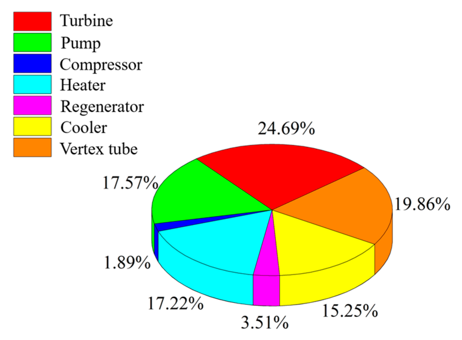
Under basic working conditions, the thermal and exergy efficiencies of the system are 7.38% and 27.09%, respectively. The liquefaction ratio of the CO2 working medium through a vortex tube can reach 74.76%. The exergy analysis shows that the turbine is the component with the largest exergy destruction in the system, accounting for 24.69% of the total exergy destruction of the system, followed by the vortex tube, pump, heater and cooler.
(2)
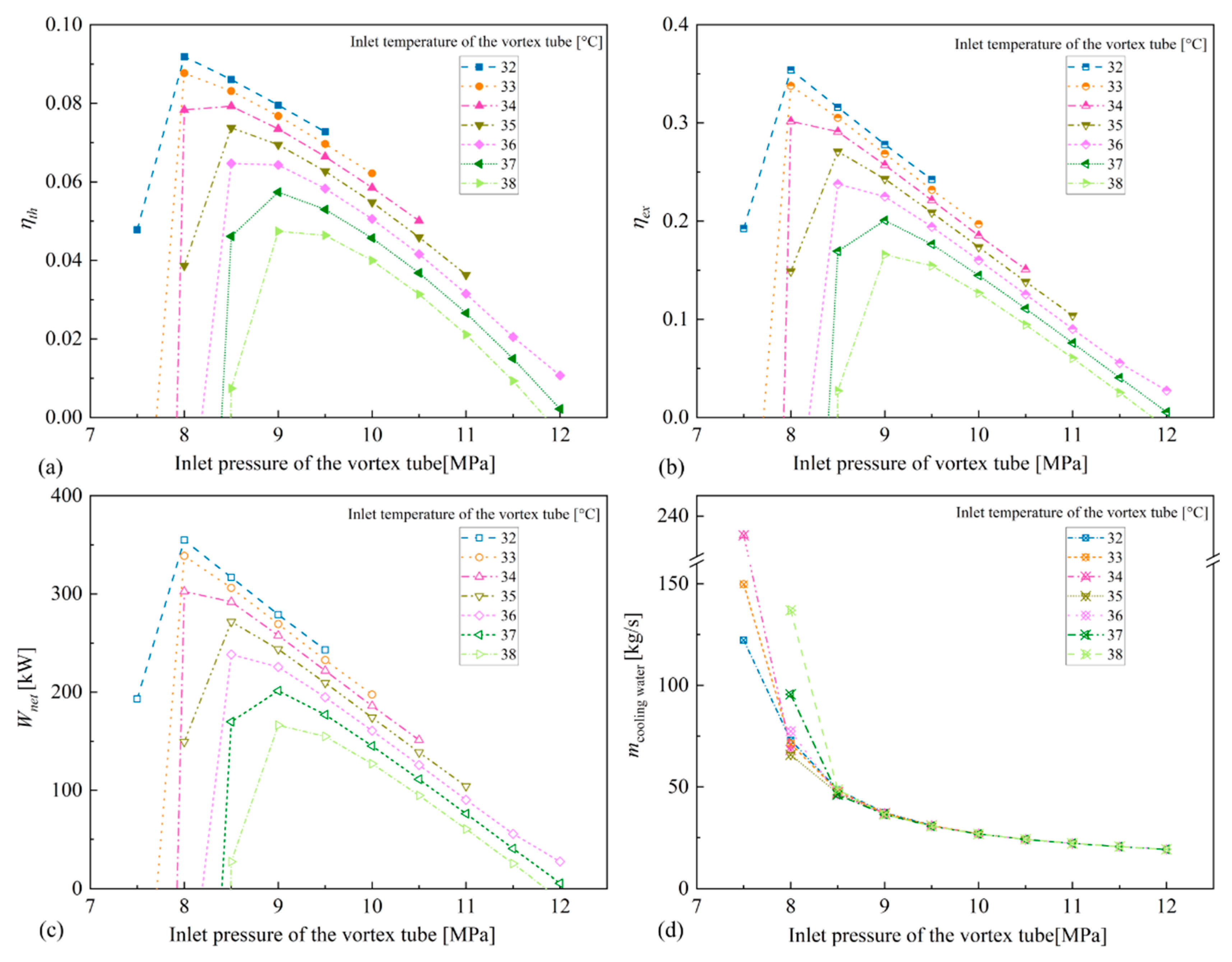
The thermal and exergy efficiencies of the system first increase and afterward decrease with the increase in the vortex tube’s inlet pressure, and increase monotonously with the increase in the vortex tube’s outlet pressure and the vortex tube’s inlet temperature. The system’s thermal and exergy efficiencies increase gradually with the increase in the turbine component’s efficiency, among which the turbine’s efficiency has a greater influence on the system’s performance.
(3)
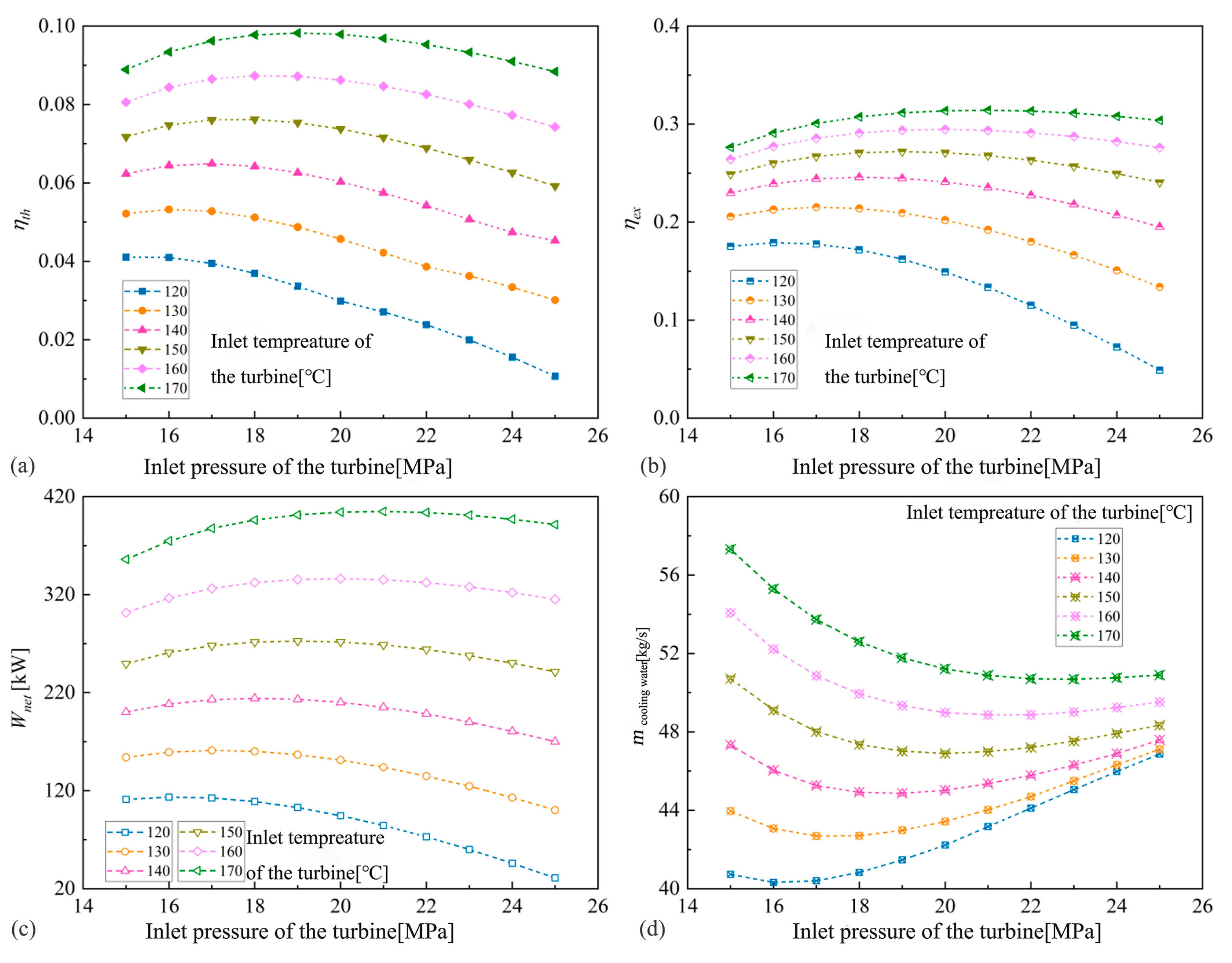
The thermal efficiency and exergy efficiency of the system increase with the increase in the turbine’s inlet temperature. When the turbine’s inlet temperature is between 130 °C and 170 °C, due to the opposite effect of the turbine and pump on efficiency, the system’s efficiency first increases and then decreases as the turbine’s inlet pressure increases.
(4)
The total flow of cooling water required for condensing subcritical CO2 in the system gradually decreases with the increase in the vortex tube’s inlet pressure, and decreases first and then increases with the increase in the inlet pressure of the turbine.
(5)
The effective condensation of subcritical CO2 can be achieved by using a vortex tube. The CO2 liquefaction ratio decreases continuously with the increase in the inlet temperature of the vortex tube and increases continuously with the increase in the inlet pressure of the vortex tube.
The innovation of this article is to propose a transcritical CO2 power system that is not limited by ambient temperature. This system can be used independently or coupled with a conventional transcritical CO2 power cycle to supplement the weakness of the conventional cycle, which cannot operate at ambient temperatures greater than 30 °C. This article only conducts thermodynamic analysis on the system, and in the future, thermal economic analysis can be conducted on the system.

Author Contributions

Writing—original draft preparation and method proposal, H.R.; program compilation, Z.K.; data collation and chart drawing, P.G.; writing—review and editing, M.W. All authors have read and agreed to the published version of the manuscript.

Funding

This research was funded by the National Natural Science Foundation of China, fundingnumber 51706179; and Shaanxi Natural Science Basic Research Program, funding number 2023-JC-YB-372.

Data Availability Statement

The data that support the findings of this study are available from the corresponding author upon reasonable request.

Conflicts of Interest

The authors declare no conflict of interest.

References

  1. Tao, D.; Lijun, L.; Zhen, L. Analytics of rankine cycle system using CO2 as working fluid. J. Eng. Thermophys. 2015, 36, 410–413. [Google Scholar]
  2. Pan, L.; Li, B.; Wei, X.; Li, T. Experimental investigation on the CO2 transcritical power cycle. Energy 2016, 95, 247–254. [Google Scholar] [CrossRef]
  3. Kim, Y.M.; Kim, C.G.; Favrat, D. Transcritical or supercritical CO2 cycles using both low- and high-temperature heat sources. Energy 2012, 43, 402–415. [Google Scholar] [CrossRef]
  4. Li, H.; Sun, E.; Xu, J. Construction and analysis of supercritical carbon dioxide cycle with multi-stage regenerative-compression. Proc. CSEE 2020, 40, 211–221. [Google Scholar]
  5. Dai, B.; Li, M.; Ma, Y. Thermodynamic analysis of carbon dioxide blends with low GWP (global warming potential) working fluids-based transcritical Rankine cycles for low-grade heat energy recovery. Energy 2014, 64, 942–952. [Google Scholar] [CrossRef]
  6. Yang, M.-H. The performance analysis of the transcritical Rankine cycle using carbon dioxide mixtures as the working fluids for waste heat recovery. Energy Convers. Manag. 2017, 151, 86–97. [Google Scholar] [CrossRef]
  7. Xia, J.; Wang, J.; Zhang, G.; Lou, J.; Zhao, P.; Dai, Y. Thermo economic analysis and comparative study of transcritical power cycles using CO2 based mixtures as working fluids. Appl. Therm. Eng. 2018, 144, 31–44. [Google Scholar] [CrossRef]
  8. Pan, L.S.; Wei, X.L.; Shi, W.X. Theoretical investigation on a novel CO2 transcritical power cycle. J. Eng. Thermophys. 2015, 36, 1182–1185. [Google Scholar]
  9. Pan, L.; Li, B.; Shi, W.; Wei, X. Optimization of the self-condensing CO2 transcritical power cycle using solar thermal energy. Appl. Energy 2019, 253, 113608. [Google Scholar] [CrossRef]
  10. Li, D.; Baek, J.S.; Groll, E.A.; Lawless, P.B. Thermodynamic analysis of vortex tube and work output expansion devices for the transcritical carbon dioxide cycle. In Proceedings of the Fourth IIR-Gustav Lorentzen Conference on Natural Working Fluids Purdueurdue University, West Lafayette, IN, USA, 25–28 July 2000; pp. 433–440. [Google Scholar]
  11. Oberti, R.; Lagrandeur, J.; Poncet, S. Numerical benchmark of a Ranque–Hilsch vortex tube working with subcritical carbon dioxide. Energy 2023, 263, 125793. [Google Scholar] [CrossRef]
  12. Ambedkar, P.; Dutta, T. Analysis of various separation characteristics of Ranque-Hilsch vortex tube and its applications—A review. Chem. Eng. Res. Des. 2023, 191, 93–108. [Google Scholar] [CrossRef]
  13. Zhao, P.; Xu, W.; Gou, F.; Fan, G.; Wang, J. Performance analysis of a self-condensation compressed carbon dioxide energy storage system with vortex tube. J. Energy Storage 2021, 41, 102995. [Google Scholar] [CrossRef]
  14. Hu, Z.; Li, R.; Yang, X.; Yang, M.; Day, R.; Wu, H. Energy separation for Ranque-Hilsch vortex tube: A short review. Therm. Sci. Eng. Prog. 2020, 19, 100559. [Google Scholar] [CrossRef]
  15. Groll, E.A. Recent advances in the transcritical CO2 cycle technology. In Proceedings of the 8th National & 7th ISHMT-ASME Heat & Mass Transfer conference: IIT Guwahati India, Guwahati, India, 4–6 January 2006. [Google Scholar]
  16. Groll, E.A.; Kim, J.H. Review of recent advances toward transcritical CO2 cycle technology. HAVCR Res. 2007, 13, 499–520. [Google Scholar]
  17. Sarkar, J. Cycle parameter optimization of vortex tube expansion transcritical CO2 system. Int. J. Therm. Sci. 2009, 48, 1823–1828. [Google Scholar] [CrossRef]
  18. Ma, J.; Liu, C.; Hou, Y. Thermodynamic analysis of transcritical CO2 refrigeration cycle with different expansion device. China Acad. J. Electron. Publ. House 2012, 33–39. [Google Scholar]
  19. Liu, Y.F.; Sun, Y.; Zhang, H.; Tang, D.P.; Zhong, W.X.; Wang, D.L. Research on Performance of Carbon Dioxide Trans-critical Refrigeration Cycle with Vortex Tube Expansion. Chin. J. Refrig. Technol. 2019, 39, 11–15. [Google Scholar]
  20. Mansour, A.; Oberti, R.; Nesreddine, H.; Poncet, S. Thermodynamic analysis of a transcritical CO2 heat pump integrating a vortex tube. Appl. Therm. Eng. 2023, 224, 120076. [Google Scholar] [CrossRef]
  21. Wang, J.F.; Liao, G.L.; Zuo, Q.R.; Zhao, P.; Wu, W.F.; He, Z.L.; Dai, Y.P. A Transcritical Carbon Dioxide Power Generation System Based on Vortex Tube. CN 111852602B, 22 June 2020. [Google Scholar]
  22. Zhang, Q.; Luo, Z.; Zhao, Y.; Cao, R. Performance assessment and multi-objective optimization of a novel transcritical CO2 trigeneration system for a low-grade heat resource. Energy Convers. Manag. 2020, 204, 112281. [Google Scholar] [CrossRef]
Figure 1. Structure of two kinds of vortex tube. (a) Conventional vortex tube. (b) Vortex tube used in subcritical CO2 self-condensation [13,14].
Energies 16 03723 g001
Figure 2. Flowchart of the transcritical carbon dioxide power system.
Energies 16 03723 g002
Figure 3. The T-s diagram of the system under design operation.
Energies 16 03723 g003
Figure 4. The internal exergy destruction distribution diagram of each component of the TCPC system under basic working conditions.
Energies 16 03723 g004
Figure 5. The influence of inlet pressure and temperature of vortex tube on the system’s performance. (a) System thermal efficiency. (b) System exergy efficiency. (c) System net output power. (d) Mass flow rate of the cooling water.
Energies 16 03723 g005
Figure 6. The influence of the inlet pressure of the vortex tube on the component work with the inlet temperature of the vortex tube at 35 °C.
Energies 16 03723 g006
Figure 7. The influence of vortex tube’s inlet pressure and inlet temperature on the liquefaction ratio of CO2.
Energies 16 03723 g007
Figure 8. The influence of inlet pressure and outlet pressure of vortex tube on the system’s performance. (a) System thermal efficiency. (b) System exergy efficiency. (c) System net output power. (d) Mass flow rate of the cooling water.
Energies 16 03723 g008
Figure 9. The influence of vortex tube’s inlet and outlet pressure on the liquefaction ratio of CO2.
Energies 16 03723 g009
Figure 10. The influence of turbine’s inlet pressure on the component’s work.
Energies 16 03723 g010
Figure 11. The influence of turbine’s inlet pressure and temperature on the system’s performance. (a) System thermal efficiency. (b) System exergy efficiency. (c) System net output power. (d) Mass flow rate of the cooling water.
Energies 16 03723 g011
Figure 12. The influence of turbine component’s efficiency on the system’s performance. (a) The variation of system thermal efficiency with the efficiency of turbine components (b) The changing law of system exergy efficiency with the efficiency of turbine components. (c) The variation of system net output power with the efficiency of turbine components. (d) The changes of turbine output power, pump consumed power, and compressor consumed power with the efficiency of the turbine. (e) The changes of turbine output power, pump consumed power, and compressor consumed power with the efficiency of the pump. (f) The changes of turbine output power, pump consumed power, and compressor consumed power with the efficiency of the compressor.
Energies 16 03723 g012
Table 1. Main design parameters of the system.
ParametersValue
Ambient pressure/MPa0.101
Ambient temperature/°C25
Minimum system pressure/MPa5
Maximum system pressure/MPa25
Expansion ratio2.353
Heat source’s pressure/MPa1.5
Heat source’s inlet temperature/°C160
Heat source’s outlet temperature/°C73.20
Turbine’s inlet temperature/°C150
Vortex tube’s inlet temperature/°C35
Vortex tube’s inlet pressure/MPa8.5
Vortex tube’s outlet pressure/MPa6.5
Cooling water’s inlet temperature/°C25
Cooling water’s outlet temperature/°C42.40
Adiabatic efficiency of vortex tube nozzle0.8
Mass fraction of cold gas0.5
Isentropic efficiency of compressor0.85
Isentropic efficiency of turbine0.85
Pump’s isentropic efficiency0.8
Heat exchanger pinch temperature difference/°C5
Table 2. Detailed thermodynamic parameters at each state point under the design parameters of the system.
Logistics Status PointPressure
/MPa
Temperature
/°C
Enthalpy/
kJ·kg−1
Entropy/
kJ·kg−1
16.525.44276.701.2546
22049.51298.971.2685
32068.19345.371.4082
420150523.191.8796
58.578.69484.641.8991
68.554.55438.241.7621
78.552.12431.931.7428
88.535308.841.3505
116.527.12403.941.6806
128.546.26413.341.6851
131.5160675.991.9415
141.573.20307.670.9931
150.125104.920.3672
160.142.40177.650.6043
Table 3. Exergy destruction calculations in the system.
Components E ˙ D , k
Compressor W ˙ c + E ˙ 11 E ˙ 12
Pump W ˙ p + E ˙ 1 E ˙ 2
Turbine E ˙ 4 E ˙ 5 W ˙ t
Vortex tube E ˙ 8 E ˙ 1 E ˙ 11
Heater E ˙ 13 E ˙ 14 + E ˙ 3 E ˙ 4
Regenerator E ˙ 5 E ˙ 6 + E ˙ 2 E ˙ 3
Cooler E ˙ 7 E ˙ 8 + E ˙ 15 E ˙ 16
Table 4. Model validation results.
State PointRef. [22]This StudyRelative Error of Calculated Temperature Results
PressureTemperaturePressureTemperature
15.7320.005.7320.00
21230.101230.060.13%
31256.901256.930.05%
412220.0012220.00
55.73156.005.73155.730.17%
65.7345.005.7345.000
75.7334.505.7334.450.14%
1c8.4188.008.4187.980.01%
2c8.452.208.452.170.06%
3c8.436.008.436.00
4c4.610.904.610.870.28%
5c4.610.904.610.870.28%
6c5.7327.505.7327.440.22%
7c4.610.904.610.870.28%
8c3.975.003.975.00
9c3.975.003.975.00
Table 5. Main performance parameters of the system.
Performance ParametersValues
Liquefaction ratio/%74.76
Thermal efficiency/%7.38
Exergy efficiency/%27.09
Compressor’s power consumption/kW65.67
Pump’s power consumption/kW461.14
Turbine’s output power/kW798.53
Net output power/kW271.72
Disclaimer/Publisher’s Note: The statements, opinions and data contained in all publications are solely those of the individual author(s) and contributor(s) and not of MDPI and/or the editor(s). MDPI and/or the editor(s) disclaim responsibility for any injury to people or property resulting from any ideas, methods, instructions or products referred to in the content.

