Article

Supercritical Heat Transfer and Pyrolysis Characteristics of n-Decane in Circular and Rectangular Channels

1
College of Civil Aviation Safety Engineering, Civil Aviation Flight University of China, Deyang 618307, China
2
Key Laboratory of Fire Science and Safety Engineering of Sichuan Province, Deyang 618307, China
3
School of Chemical Engineering, Sichuan University, Chengdu 610065, China
*
Author to whom correspondence should be addressed.
Energies 2023, 16(9), 3672; https://doi.org/10.3390/en16093672
Submission received: 13 February 2023 / Revised: 22 March 2023 / Accepted: 19 April 2023 / Published: 24 April 2023
(This article belongs to the Section A4: Bio-Energy)

Abstract

:
In this research, the effects of different channel cross-section shapes on the flow, heat transfer and pyrolysis characteristics of n-decane were analyzed and compared based on CFD simulations. The interactions between cracking, heat transfer and flow field in a circular tube and a rectangular tube were studied. The results showed that the mean pressure drop in the rectangular channel is 1.18 times as high as that in the circular channel with pyrolysis due to its smaller equivalent diameter. The maximum value of the chemical heat sink in the rectangular channel is 1.6 times as high as that in the circular channel. The high temperature zone of any cross section in the rectangular channel is much larger than that in the circular channel due to the superposition of the boundary layer and lower turbulent kinetic energy in the corners of the rectangular channel. The maximum value of the Nu in the circular channel is 1.3 times as high as that in the rectangular channel with pyrolysis due to larger heat capacity, lower viscosity and higher wall shear stress.

1. Introduction

The thermal protection of scramjet depends on the regenerative cooling technology of endothermic hydrocarbon fuels (EHFs) [1,2,3,4]. During a regenerative cooling process, the heat transfer and pyrolysis processes of EHFs are affected by differences in the channel cross-sectional geometry. Therefore, mastering the heat-transfer and pyrolysis processes is important for the design of cooling channels.
At present, most of the existing literature has focused on the pyrolysis characteristics of EHFs in the uniformly heated circular channels [5,6,7]. Ward et al. [8,9] proposed the idea of proportional product distribution (PPD) through a set of experiments in a circular tube. Jiang et al. [10] studied the pyrolysis processes of supercritical hydrocarbon fuel in a circular tube. Zhu et al. [11] experimentally studied the thermal cracking of n-decane at supercritical pressures in an electrically heated vertical circular tube. Zhao et al. [12] proposed the experimental analysis method of regenerative cooling microchannel electric heating tubes and introduced a secondary reaction model, improving the applicability of the cracking mechanism at high temperatures.
However, the rectangular cooling channel is a common structure of scramjet [13]. Bao et al. [1] studied numerically the nonuniformities of the velocity, temperature and conversion of EHFs in an asymmetrically heated rectangular cooling channel. Jiang et al. [14] investigated numerically the effect of geometry on flow processes of EHFs in the asymmetric heating and cooling channels with rectangular, circular, trapezoid or triangular cooling channels. Li et al. [15] investigated experimentally the thermal cracking behavior of EHFs in the circumferentially uniformly heated cooling channels with rectangular, square and circular cross sections. Li et al. [16] studied experimentally the heat transfer and cracking processes of EHFs in rectangular tubes with different aspect ratios.
It should be noted that the flow, heat-transfer and pyrolysis processes of EHFs in the circumferentially uniformly heated rectangular tubes were seldomly studied based on numerical simulation to obtain the differences between microcircular and rectangular tubes. Moreover, the interactions between flow field, cracking and heat transfer in different cooling channel shapes need further study.
In this research, the numerical models, which are composed of shear-stress transport (SST) kω turbulence models and a global reaction model with Peng–Robinson equation and one-fluid van der Waals mixing rules, were validated against the experimental data published in the literature. This was done to demonstrate the reliability of the CFD simulations for the supercritical flow and heat-transfer characteristics of n-decane during pyrolysis. Based on the validated model, the influences of the cross-section shape on the flow, heat transfer and cracking processes of supercritical n-decane were numerically studied in the circular and rectangular tubes. The mechanisms of supercritical heat transfer in the circumferentially uniformly heated circular and rectangular tubes were studied and analyzed.

2. Simulation

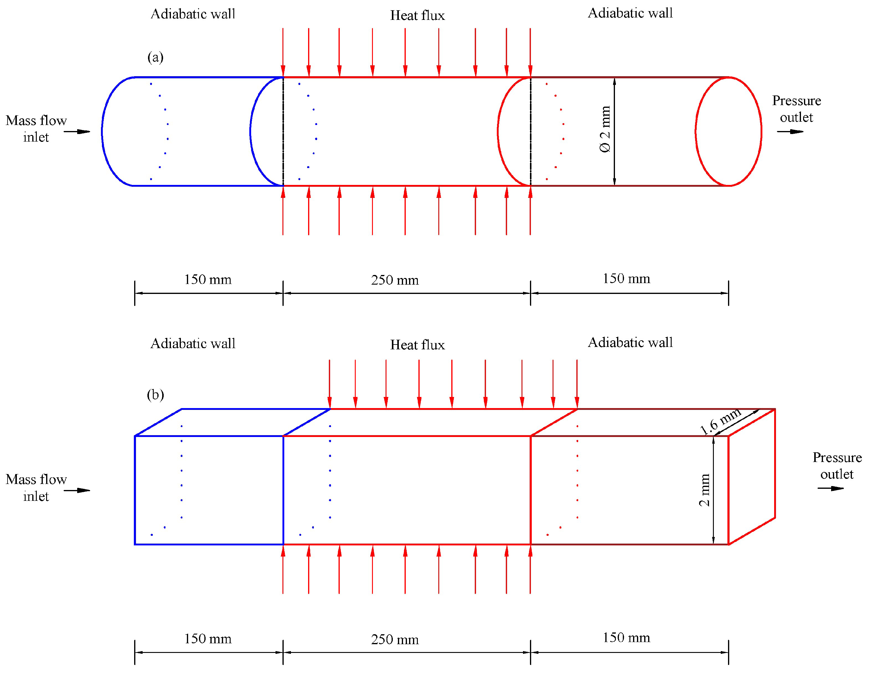
2.1. Computing Domain and Boundary Conditions

A 2D axisymmetric swirl model and a 3D model were adopted for the uniformly heated horizontal circular and rectangular tubes (Figure 1). Due to the symmetry of the rectangular tube, a quarter of the computing domain was used. The axisymmetric swirl model was adopted because of the axial symmetry of the circular tube. The heated section length was 250 mm, and a 150 mm long insulation section was added at both the inlet and the outlet. With reference to the experimental data provided by Zhou et al. [17], the m ˙ and inlet temperature of n-decane in our simulation were set to 0.8 g·s−1 and 673.15 K, respectively. At the outlet, a pressure outlet boundary was applied, where the pressure was specified at 3.5 MPa. The qw of the heated wall was 0.48 MW·m−2. The walls of the inlet and outlet unheated sections were all treated as adiabatic. All the walls in the models were nonslipping. From Figure 1, the only difference between the two computational domains lay in the geometry of the cross section.

2.2. Reaction Model

The global reaction model developed by Zhou et al. [17] is expressed as:
C 10 H 22 0.07 H 2 + 0.31 CH 4 + 0.46 C 2 H 6 + 0.89 C 2 H 4 + 0.17 C 3 H 8 + 0.37 C 3 H 6 + 0.05 C 4 H 10 + 0.09 C 4 H 8 + 0.04 C 4 H 6 + 0.77 C 5 +
The reaction rate and reaction rate constant are given as follows:
ω R = d C R / d t = K C R
K = k 0 exp ( E a R T )

2.3. Theoretical Formulation and Numerical Treatment

The mass, momentum, energy and composition conservation equations are as follows:
( ρ u ) = 0
( ρ u u ) = p + τ e f f
( ρ u e t ) = ( λ e f f T ) ( p u ) + s h
( ρ u Y j ) = J j + R j
Zhang et al. [3] and Zhao et al. [18] used the Peng–Robinson equation and SST kω turbulence model to study the thermal behavior of the pyrolysis zone. Moreover, the turbulent flow was also simulated using the kε model with enhanced wall treatment. Therefore, the SST kω and kε turbulence models were used in this study. The SST kω turbulence model [19,20] is given by:
( ρ u k ) = ( ( μ + μ t σ k ) k ) + G k Y k
( ρ u ω ) = ( ( μ + μ t σ ω ) ω ) + G ω Y ω + D ω
The kε turbulence model is given by:
( ρ u k ) = ( ( μ + μ t σ k ) k ) + G k + G b ρ ε Y M
( ρ u ε ) = ( ( μ + μ t σ ε ) ε ) + C 1 ε ε k ( G k + C 3 ε G b ) C 2 ε ρ ε 2 k
The meaning of each variable is described in [21].
Table 1 presents the comparisons of the kε and SST kω models. The maximum relative errors of the mass fraction of unreacted n-decane predicted by the SST kω and kε models were 0.54% and 2.88%, respectively. Therefore, the SST kω turbulent model was adopted to calculate the pyrolysis characteristics of n-decane.

2.4. Property Evaluations and Solution Method

As a typical hydrocarbon fuel and a major composition of aviation fuels, the λ and μ of n-decane and the cracking component were calculated via NIST (SUPERTRAPP) software [22]. The critical pressure and the critical temperature of n-decane were 2.15 MPa and 617.7 K, respectively [22]. Thermal cracking occurs when n-decane is heated to approximately 770 K [23]. The Peng–Robinson equation [24] was adopted to solve the density of the mixtures. One-fluid van der Waals mixing rules [25] were used to calculate the critical temperature, critical pressure and critical specific volume of the mixture. The computing methods of other physical properties are described in [1].
Figure 2 shows the validation between the simulated fluid density and the NIST data. As illustrated in Figure 2, the relative error was less than 2.6%, which indicated that the Peng–Robinson equation was suitable for calculating the density of the mixtures. The λ and μ are based on NIST data directly, so no verification is required.
The pressure-based solver was chosen to solve the governing equations for the flow and heat-transfer process with pyrolysis. The equations were discretized with the second-order upper difference scheme. Pressure–velocity coupling was solved using the SIMPLE, SIMPLEC, PISO and coupled algorithms in Fluent. The convergence criteria of all equations were less than 10−6.
Table 2 presents the comparisons of the SIMPLE, SIMPLEC, PISO and coupled algorithms. The relative errors of the unreacted n-decane mass content and fluid temperature between the simulation results calculated by SIMPLE, SIMPLEC, PISO and the coupled algorithms and the experimental data were relatively small. However, the calculation times of SIMPLE, SIMPLEC and the coupled algorithm were 54 min, 93 min and 131 min, respectively. Considering the calculation efficiency, the SIMPLE algorithm was adopted to calculate the pyrolysis characteristics of n-decane.

2.5. Parameter Calculation

The Tf is calculated as follows:
T f = A c p ρ u T d A A c p ρ u d A
The h is calculated by Equation (13):
h = q w T w T f
The Tw in the wet perimeter is calculated as follows:
T w = A T w , i d A A
where Tw,i is the wall temperature of the grid node i.
The Reynolds number is calculated as follows:
R e = ρ u d h μ = m ˙ d h A μ
The Prandtl number is calculated as follows:
P r = c p μ λ
The Nusselt number is calculated as follows:
N u = h d h λ = a Re b Pr c = a ( m A μ d h ) b ( c p μ λ ) c
The pressure drop is calculated by Equation (18) and verified by Equation (19), as recommended by Shi et al. [26]:
Δ p = p i n p o u t
Δ p = 0.3164 Re 0.25 l d h 1 2 ρ u 2 = 0.3164 d h 1.25 l m 1.75 μ 0.25 2 ρ A 2

3. Validations

3.1. Grid Independence Study

Several grids with different numbers of elements were generated, and the specifications of the grids are listed in Table 3. In the near wall area of the fluid domain, the computational accuracy of the boundary layer mesh is ensured by defining the distance from the first layer mesh point to the boundary (0.001 mm) and the grid growth rate (1.2). The radial grids were selected from among 36, 50, 70 and 98. The axial grids were selected from among 1326, 1857, 2600 and 3640. From the analysis of the Tf and Tw at different grid combinations, the grid was reduced from 70 × 2600 to 50 × 1857, and the relative errors were 0.1% and 0.1%, respectively. Therefore, a grid size with 70 × 2600 (radial × axial) was used as the calculation baseline for the circular tube. Similarly, a grid size of 600 × 70 × 50 (X × Z × Y) was used as the calculation baseline for the rectangular tube. In this study, y+ was kept as less than 1.0 under all conditions.

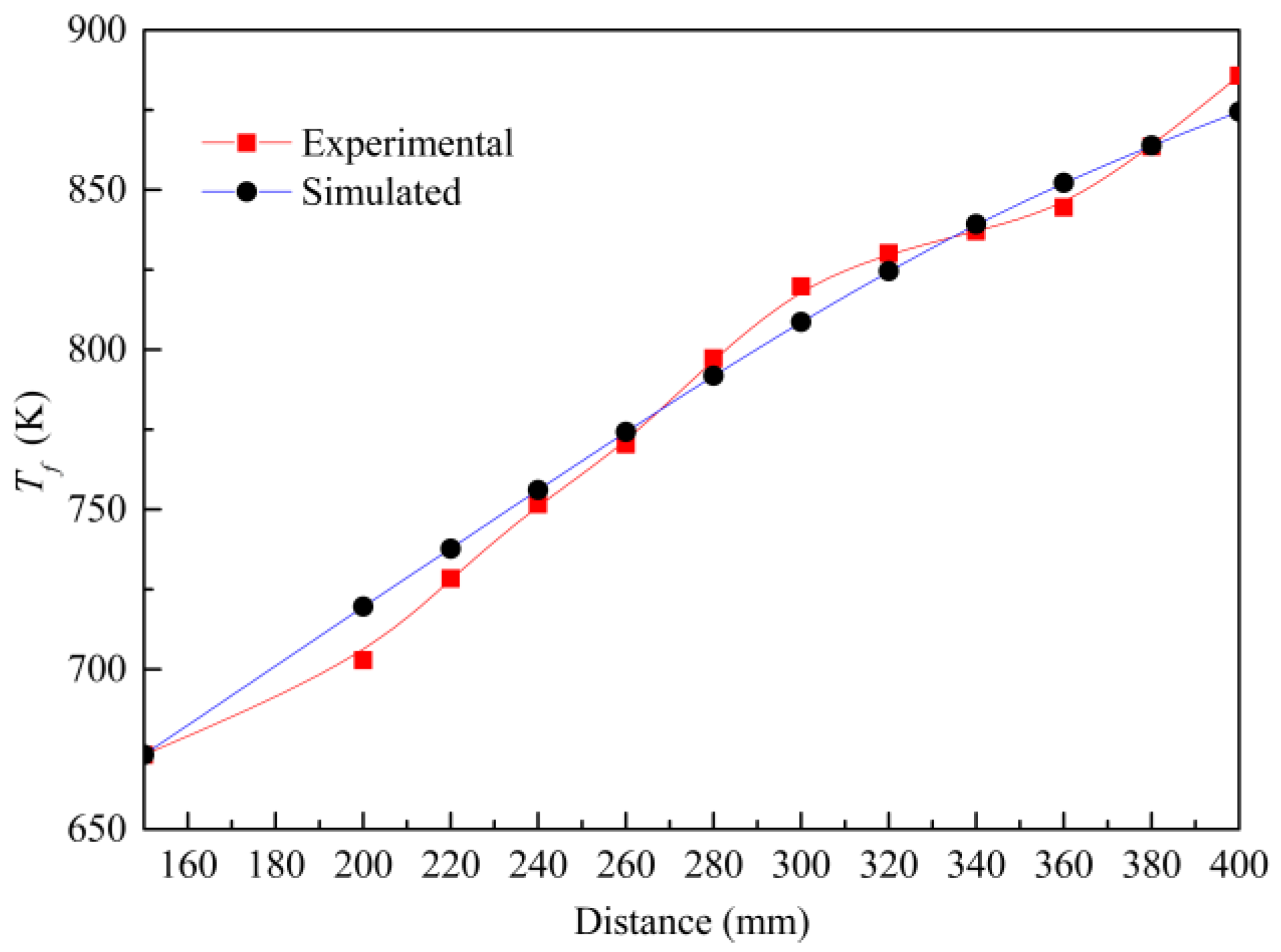
3.2. Model Validation

The experimental results provided by Zhou et al. [17] were used to verify the model. The experimental conditions are listed in Table 4. Table 5 shows the comparisons of the unreacted n-decane mass content and fluid temperature at X = 400 mm. The relative errors of the fluid temperature and the unreacted n-decane mass content were 1.26% and 0.54%, respectively.
Figure 3 presents the comparisons between the simulated and experimental Tf. The maximum relative error of Tf was 2.4%. Therefore, the current numerical model was adopted to calculate the influence of different channel cross-section shapes on the heat transfer of n-decane with pyrolysis.
Figure 4 shows a comparison between the pressure drops calculated using Equations (18) and (19). The maximum relative error of the pressure drop between the simulated results and the calculation of Equation (19) was 3.1%. Therefore, the current numerical model was adopted to calculate the influence of different channel cross-section shapes on the pressure drop.

4. Results and Analysis

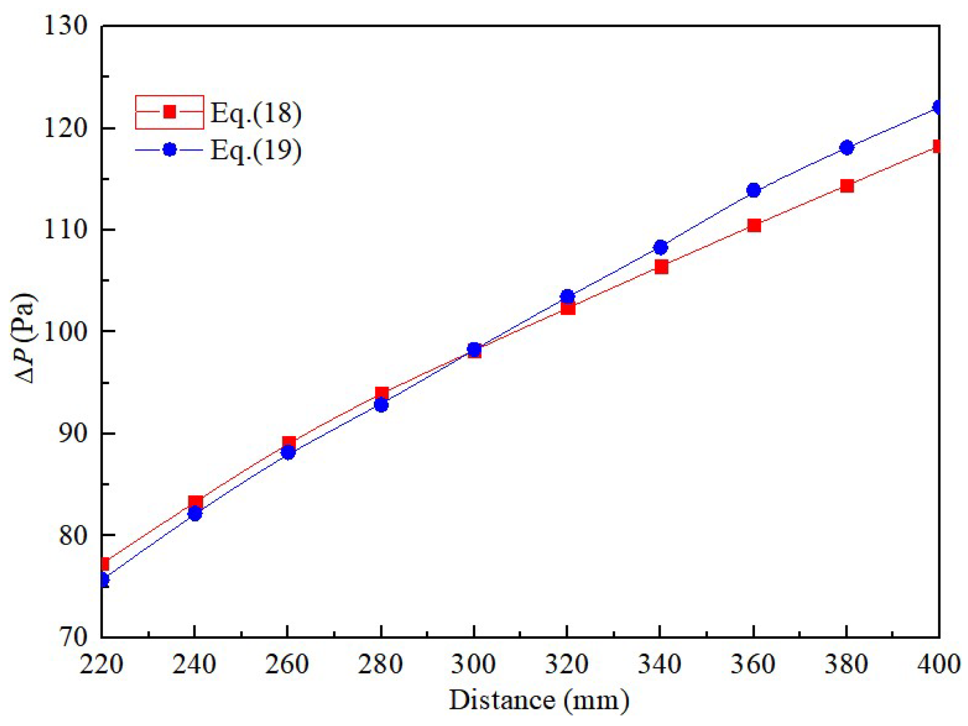
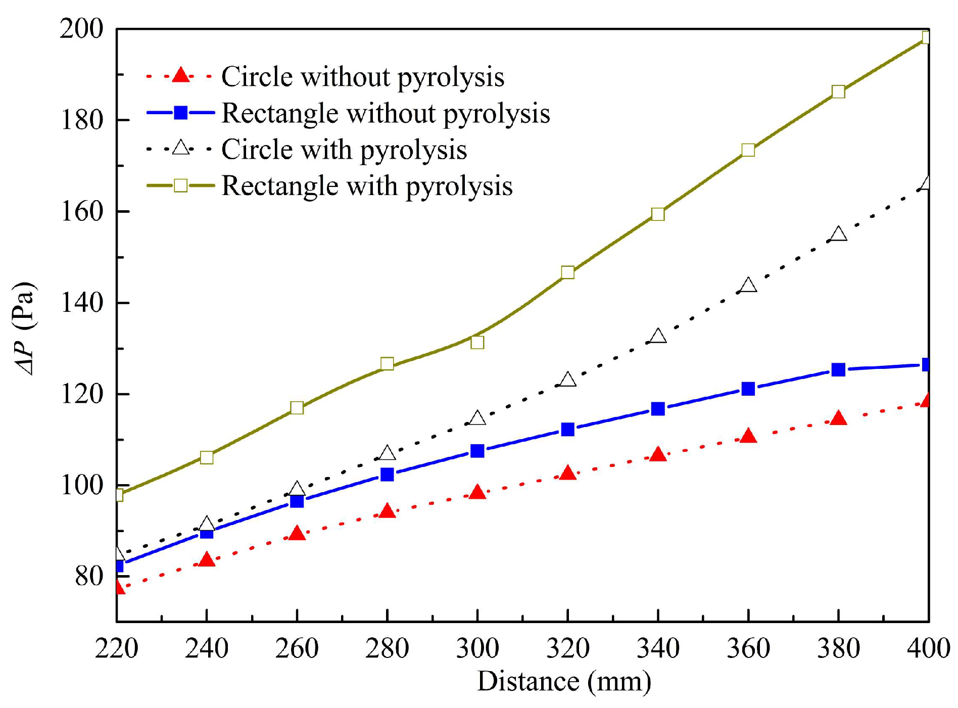
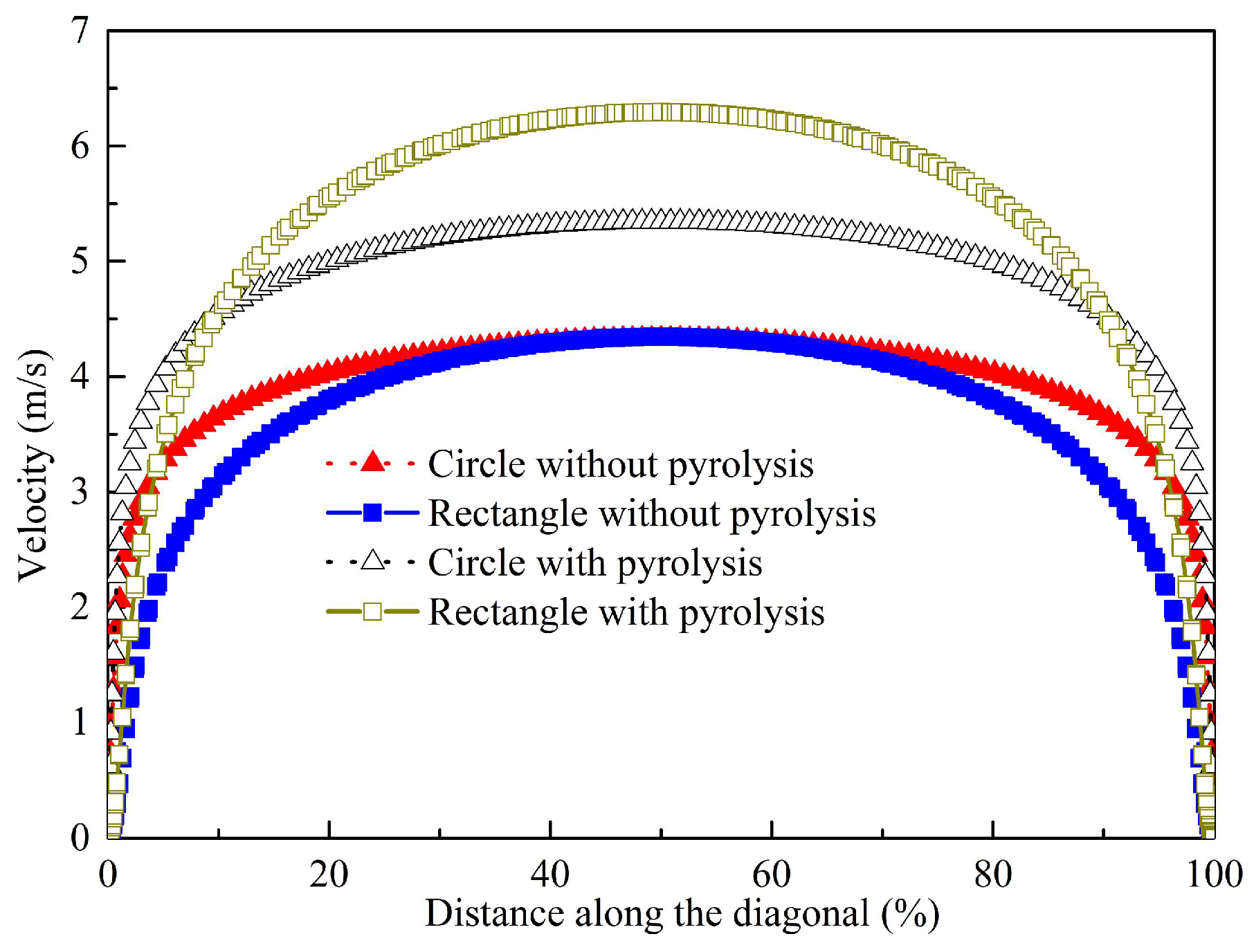
4.1. Influences of Geometry on Flow

Figure 5 indicates that the pressure drop (ΔP) increases gradually along the circular and rectangular channels. However, the flow resistance in the rectangular channel (R) is greater than that of the circular one (C). According to Equation (19), the equivalent diameter (1.78 mm) of the rectangular channel is smaller than that (2 mm) of the circular one. Therefore, the flow resistance in the rectangular channel is greater than that of the circular one. From Figure 5, when the cracking reaction model is adopted in the simulation, the pressure drops in both the circular and the rectangular tubes increases. The mean pressure drop per 20 mm long circular tube increased from 99 Pa to 122 Pa, while the mean pressure drop per 20 mm long rectangular tube increased from 108 Pa to 144 Pa. Therefore, the mean pressure drop in R is 1.18 times as high as that in C with pyrolysis.
Figure 6 indicates the velocity distribution along the diagonal at X = 400 mm in the circular and rectangular tubes. When the pyrolysis reaction is not adopted in the simulation, the velocity in the velocity boundary layer varies greatly. However, the maximum velocity in both the circular and rectangular tubes is 4.3 m/s. From Figure 6, when the cracking reaction is included in the simulation, the velocity in both the circular and the rectangular tubes increases. The maximum velocity in C increased from 4.3 m/s to 5.3 m/s, while the maximum velocity in R increased from 4.3 m/s to 6.3 m/s. Therefore, the maximum velocity in R is 1.18 times as high as that in C with pyrolysis. This is related to the high cracking and low density of R.

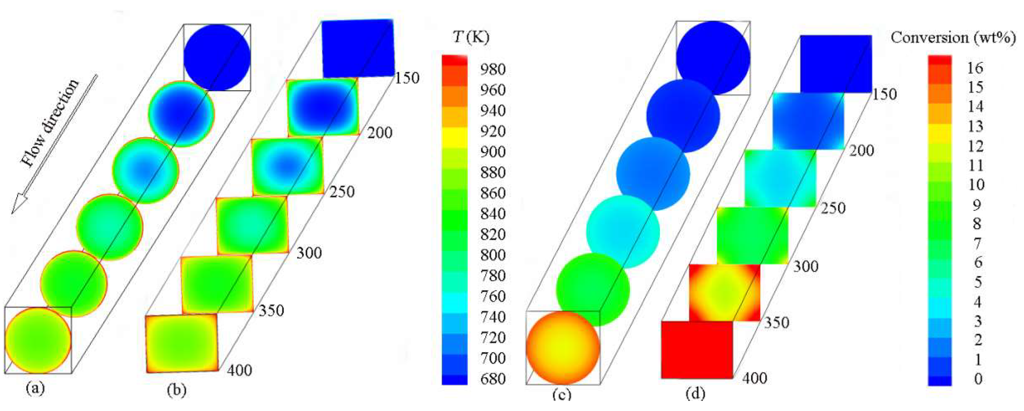
4.2. Effects of Geometry on Pyrolysis

Figure 7 presents the cloud plots of T and the conversion in C and R. In Figure 7a, it is observed that the fluid temperature gradually increases from the center to the tube wall and from the inlet to the outlet. From Figure 7b, the local high fluid temperatures are observed at the four corners of R, leading to the nonuniformity of the fluid temperatures in the rectangular section. In addition, the high-temperature zone of any cross-section in R is much larger than that in C at the same axial position. The main reason is that the boundary layers interact in the corners of R, leading to lower velocity gradients and higher wall temperatures around the corners, which are stronger than those at the circumference of C.
Figure 7c shows that the conversion in C gradually increases from the center to the tube wall and from the inlet to the outlet, which is consistent with the trend of temperature change, as shown in Figure 7a. From Figure 7c,d, the area of the high-conversion region in the rectangular tube is much larger than that in the circular tube, which is mainly due to the distribution of the temperature boundary layer in the rectangular tube, as shown in Figure 7b. From Figure 7d, the pyrolysis in the corners of R has a higher conversion, which may enhance coke deposition rates. Similar expressions were observed in [15].
The chemical heat sink is calculated as follows:
Δ H c h e m = Δ H t o t a l Δ H s e n
Figure 8a,b shows that the cracking conversion and chemical heat sink of R are higher than those of C under the same heat flux. According to Equations (2) and (3), the cracking conversion mainly depends on residence time and fluid temperature. Moreover, pyrolysis is an endothermic process, and the increasing conversion leads to the increasing chemical heat sink. The average fluid temperature of R was higher than that of C, and the higher flow velocity in R leads to lower residence time. From Figure 8c,d, compared with the circular tube, higher fluid bulk temperatures enhance thermal cracking in the rectangular tube, thus increasing the chemical heat sink. It is shown that the influence of temperature is greater than that of residence time on the chemical heat sink in rectangular tubes. Similar expressions were observed in [27].
Figure 8a,b indicates that the maximum values of the chemical heat sink and conversion in C are 198.8 kJ·kg−1 and 12.99%, respectively, while the maximum values in R are 309.4 kJ·kg−1 and 20.21%, respectively. Therefore, the maximum value of the chemical heat sink in R is 1.6 times as high that in C, and the maximum values of the chemical heat sink and conversion in the rectangular tube are 111 kJ·kg−1 and 7.2% more than those in the circular tube, respectively. From Figure 8c,d, the μ and λ of fluid in R are higher than those in C, and specific heat and density in R are smaller than that in C. The extent of cracking conversion in the rectangular tube is higher, resulting in more small molecular species being produced at the same bulk fluid temperature compared to the circular tube.

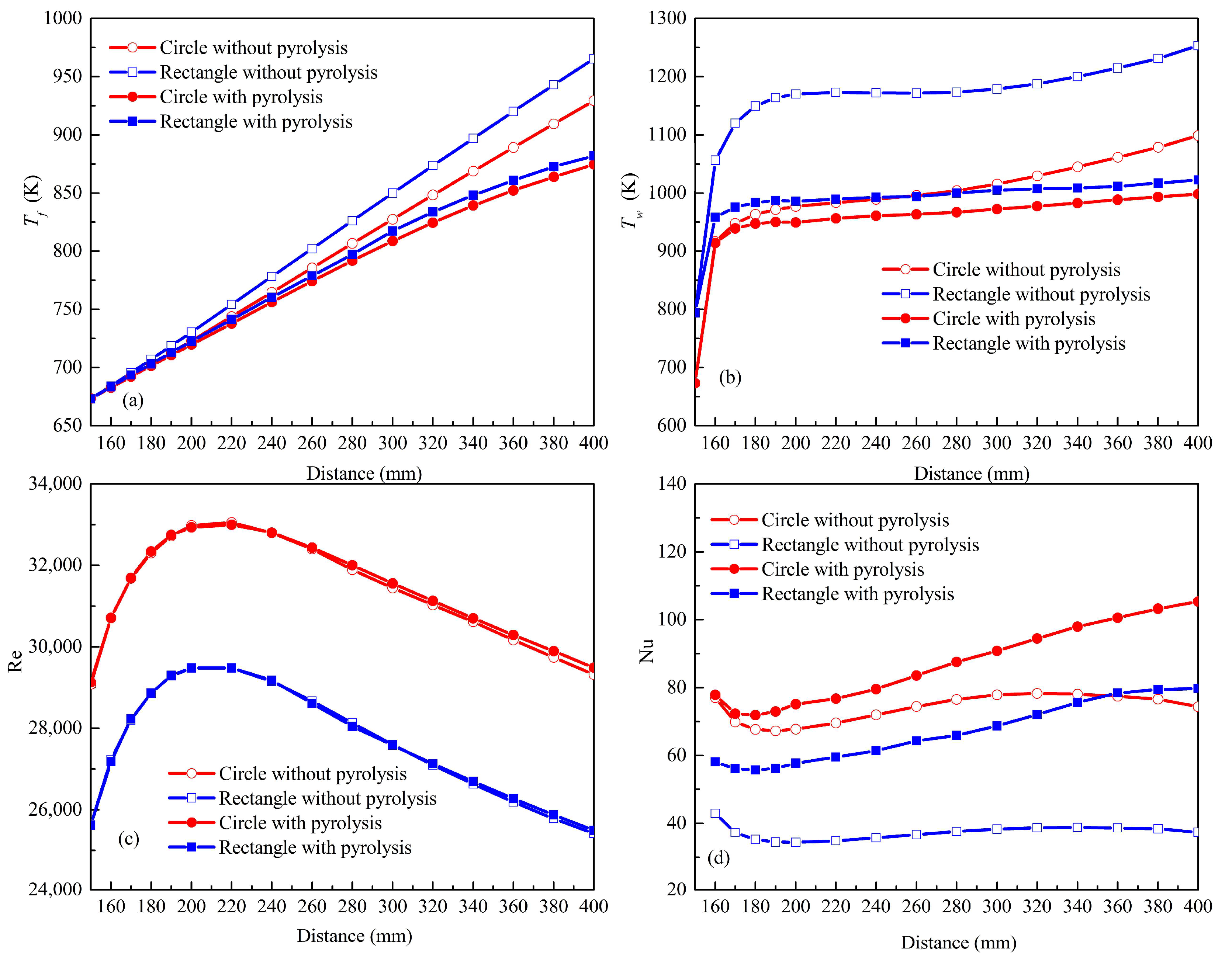
4.3. Effects of Geometry on Heat Transfer

Figure 9 indicates the distributions of the Tf, Tw, Re number and Nu number with the circular and rectangular tubes. From Figure 9a,b, the Tf increases gradually, while the Tf and Tw in C are lower than those in R. When the fuel cracking reaction model is included in the simulation, both the Tf and the Tw decrease in the circular and rectangular tubes, which indicates that the endothermic fuel pyrolysis improves the convective heat transfer by decreasing the bulk fluid temperature and increasing the flow velocity. In addition, the difference between the Tw and the Tf at the outlet of rectangular tube is 140 K, which is 17 K more than that of the circular tube. The heat transfer from the wall to the main flow is weakened by the thickening of the heat boundary in the initial heating section. Therefore, the Tw increases sharply at the initial heating section.
Figure 9c shows that the Re number first increases and then decreases with either the circular or rectangular tube. The main reason is that the viscosity coefficient decreases at about 750 K and then increases with the increase in temperature, as shown in Figure 8d. Similar expressions were observed in [19]. From Figure 9c, the Re number of the fluid is greater than 4000, so the flow is turbulent. According to the Equation (15), the Re number is proportional to the equivalent diameter, and the hydraulic diameters of C and R are 2 mm and 1.78 mm, respectively. Therefore, no matter whether the cracking model is added to the simulation, the Re number in C is larger than that in R at the same mass flux, indicating that turbulent diffusion and heat transfer are enhanced in the circular tube. Consequently, the Nu in C is relatively high compared to the Nu in R, as shown in Figure 9d. Moreover, when the cracking reaction model is adopted in the simulation, the Nu number of the fluid in both C and R increases. The maximum value of the Nu number for C is 105, while the maximum value for R is 80. Therefore, the maximum value of the Nu in C is 1.3 times as high that in R with pyrolysis.

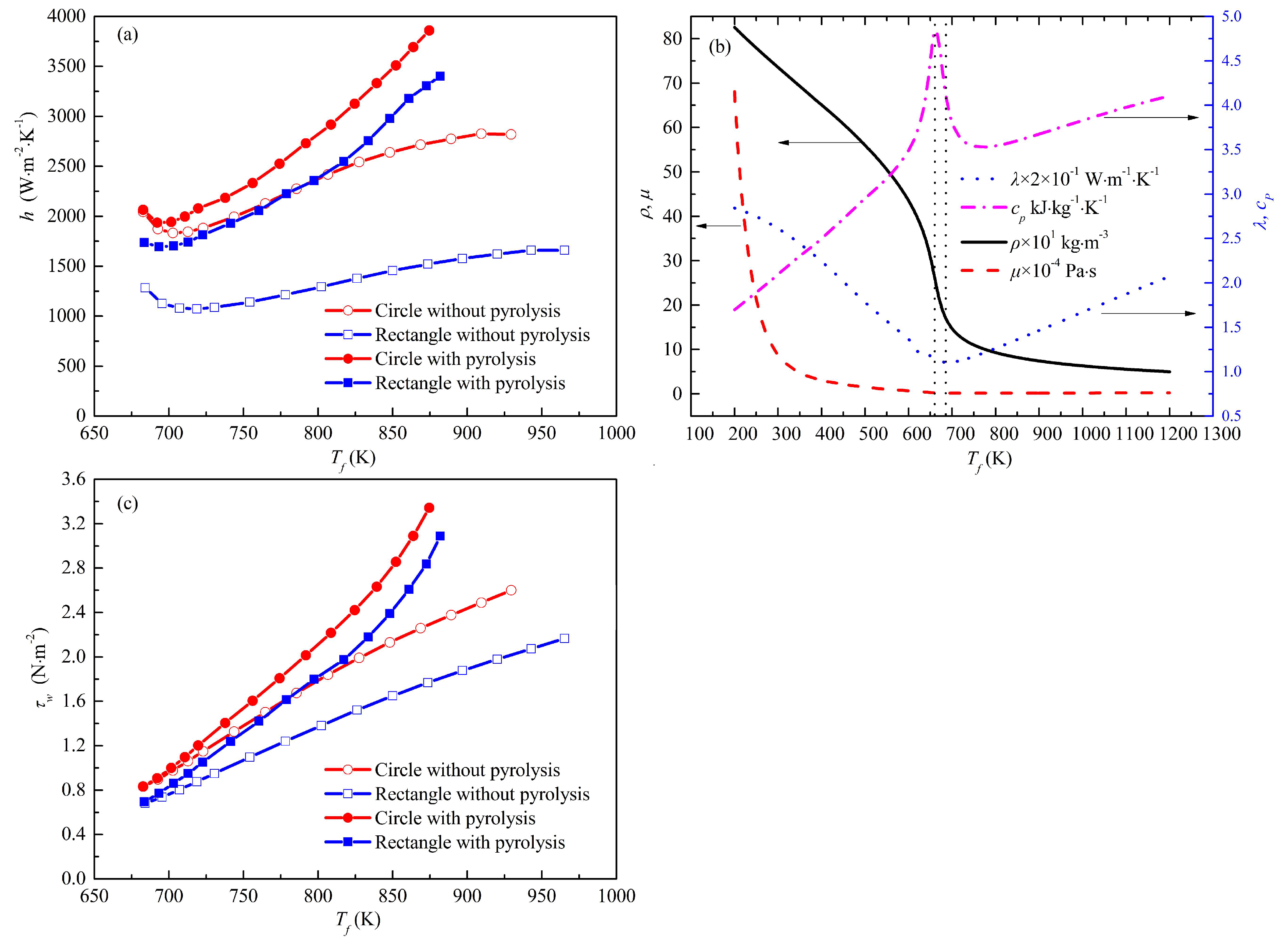
4.4. Mechanisms of Heat Transfer in the Circular and Rectangular Tubes

According to Dittus–Boelter equation and Equation (17), h can be calculated as follows:
h = 0.023 d h 0.2 ( m A ) 0.8 ( c p μ ) 0.4 λ 0.6
Figure 10a,b presents the variations in the h and the physical properties of n-decane with Tf. The maximum heat capacity and minimum thermal conductivity in the range of temperatures are shown in Figure 10b, and the corresponding temperatures are about 662 K and 692 K, respectively, which are marked by two black dotted lines. In this study, the circular and rectangular tubes have the same mass flow rate and cross-sectional area. When the Tf is greater than 673 K, both cp and λ first decrease and then increase with an increasing Tf, while μ does not obviously change. According to Equation (21), the variations in h are similar to those in cp and λ with an increasing Tf, as shown in Figure 10a.
Figure 10c shows changes in the wall shear stress (τw) with Tf. From Figure 10a,c, the τw and h show a similar change trend with the bulk fluid temperature. The τw increases the turbulence in the logarithmic law layers, leading to the increasing h. Based on the effect of pyrolysis on thermophysical properties in Section 4.3, it can be concluded that the rectangular tube has a lower convective heat-transfer coefficient due to its smaller heat capacity, larger viscosity and lower wall shear stress compared to the circular tube with pyrolysis.
Figure 11 shows that the turbulent kinetic energy (k) gradually increases along the flow direction in both C and R. In Figure 11, the k first increase and then decrease from the center to the tube wall, and the k at the wall are zero. From Figure 11a,c, when the fuel cracking reaction model is included in the simulation, the turbulent kinetic energy increases. The main reason is that the cracking reaction results in more small molecular substances, and the larger turbulent kinetic energy is conducive to the energy exchange between fluids. Therefore, the pyrolysis reaction can improve the heat-transfer performance. From Figure 11c,d, there are regions with zero turbulent kinetic energy at the four corners of the rectangle. The lower turbulent kinetic energy is unfavorable to the energy exchange between fluids. Therefore, the temperature in this area is relatively high, as shown in Figure 7b. Figure 11d shows that the four sides of the rectangle have regions with relatively large local turbulent kinetic energy. Higher k leads to the full mixing of the fluid and the destruction of the thermal boundary layer, which helps to improve the local heat-transfer performance, as shown in Figure 7b.

5. Conclusions

In this paper, the effects of different channel cross-section shapes on the heat transfer and pyrolysis characteristics of n-decane were numerically investigated under the same operation condition. The differences in cracking and heat transfer between the circular and rectangular tubes were analyzed. The conclusions can be drawn as follows:
(1)
Compared with the flow resistance in the circular channel with pyrolysis, the mean pressure drop in the rectangular channel is 1.18 times as high due to its smaller equivalent diameter. The maximum velocity in the rectangular channel is 1.18 times as high as that in the circular one with pyrolysis due to the higher pyrolysis and lower density.
(2)
The area of the high-conversion region in the rectangular tube is much larger than that in the circular tube due to the distribution of the temperature boundary layer in the rectangular tube. The maximum value of the chemical heat sink in the rectangular channel is 1.6 times as high as that in the circular one.
(3)
The high-temperature zone of any cross section in the rectangular channel is much larger than that in the circular channel due to the superposition of the boundary layer and lower turbulent kinetic energy in the corners of the rectangular channel. The maximum value of the Nu in the circular channel is 1.3 times as high as that in the rectangular one with pyrolysis due to its larger heat capacity, lower viscosity and higher wall shear stress.

Author Contributions

Conceptualization, methodology, software, validation, formal analysis, investigation, resources, data curation and writing—original draft preparation, Z.L.; writing—review and editing, visualization, supervision, project administration and funding acquisition, Z.B. All authors have read and agreed to the published version of the manuscript.

Funding

The financial support was provided by the Ministry of Education “New Engineering” Aviation Fuel Pipeline Transportation Safety Experiment and Training Base Construction Project, (grant number MHJY2022034), the Central University Basic Scientific Research Foundation—Doctorate Innovation Capability Improvement Project, (grant number PHD2023-064), the Central University Basic Scientific Research Foundation—Youth Fund Project, (grant number QJ2023-049), the Sichuan University Student Innovation Industry Training Program (grant number S202210624087) and the Central University Basic Scientific Research Business Expenses Special Funds (grant number XSB2022-009).

Institutional Review Board Statement

Not applicable.

Informed Consent Statement

Not applicable.

Data Availability Statement

Data are contained within the article.

Conflicts of Interest

The authors declare no conflict of interest.

Nomenclature

Aarea (m2)
cpspecific heat capacity (J/(kg∙K))
Ccircular tube
C, C, Cconstants in k-ε turbulence models
CRreactant concentration (kmol/m3)
dhequivalent diameter (m)
Dωcross-diffusion term
ettotal energy (J/kg)
Eaactivation energy, 269.2 kJ/mol
Gk, Gωproduction term
hheat-transfer coefficient (W/(m2∙K))
Hheat sink (kJ/kg)
J j diffusion flux of species j (m2/s)
kturbulent kinetic energy (m2/s2)
k0pre-exponential factor, 1.75 × 10¹⁵/s
Kreaction rate (1/s)
llength of the tube (m)
m ˙ mass flow rate (g/s)
NuNusselt number
ppressure (MPa)
PrPrandtl number
qheat flux (kW/m2)
rr-axis coordinate (m)
Runiversal gas constant, 8.314 × 10⁻³ (kJ/(mol·K))
Rrectangular tube
Rjnet rate of production of species j (1/s)
ωRreaction rate of reactant (kmol/(m3·s))
ReReynolds number
shheat of chemical reaction (J)
SSTshear stress transport
ttime (s)
Ttemperature (K)
u velocity vector (m/s)
XX-axis coordinate (m)
y+dimensionless distances from the wall
YY-axis coordinate (m)
Yjmass fraction of species j (%)
Yk, Yωdissipation term
ZZ-axis coordinate (m)
Greek symbols
ε dissipation rate (m2/s3)
ρdensity (kg/m3)
μviscosity (kg/(m·s))
λthermal conductivity (W/(m∙K))
τshear stress (N/m2)
σk, σω, σεturbulent Prandtl number
ωspecific dissipation rate (1/s)
Subscripts
effeffective value
fbulk fluid
ininlet
outoutlet
jspecies
sensensible
tturbulent
wwall
Superscripts
b, cindex

References

  1. Bao, W.; Zhang, S.; Qin, J.; Zhou, W.; Xie, K. Numerical analysis of flowing cracked hydrocarbon fuel inside cooling channels in view of thermal management. Energy 2014, 67, 149–161. [Google Scholar] [CrossRef]
  2. Chen, M.; Hu, Y.; Han, Z.; Peng, Z.; Zan, H. Study on influence of forced vibration of cooling channel on flow and heat transfer of hydrocarbon fuel at supercritical pressure. Therm. Sci. 2021, 26, 3463–3476. [Google Scholar] [CrossRef]
  3. Zhang, S.; Feng, Y.; Jiang, Y.; Qin, J.; Bao, W.; Han, J.; Haidn, O.J. Thermal behavior in the cracking reaction zone of scramjet cooling channels at different channel aspect ratios. Acta Astronaut. 2016, 127, 41–56. [Google Scholar] [CrossRef]
  4. Zhang, T.; Zhou, H.; Chen, Y.; Liu, P.; Zhu, Q.; Wang, J.; Li, X. Investigations on the thermal cracking and pyrolysis mechanism of China No.3 aviation kerosene under supercritical conditions. Petrol. Sci. Technol. 2018, 36, 1–9. [Google Scholar] [CrossRef]
  5. Gongnan, X.; Xiaoxiao, X.; Xianliang, L.; Zhouhang, L.; Yong, L.; Sunden, B. Heat transfer behaviors of some supercritical fluids: A review. Chin. J. Aeronaut. 2022, 35, 290–306. [Google Scholar]
  6. Mansour, M.K. Numerical study of three-dimensional conjugate heat transfer in liquid mini-scale heat sink. Heat Transf. Res. 2013, 44, 561–588. [Google Scholar] [CrossRef]
  7. Yu, B.; Zhou, W.; Qin, J.; Bao, W. Dynamic characteristics of hydrocarbon fuel within the channel at supercritical and pyrolysis condition. J. Therm. Sci. 2017, 26, 560–569. [Google Scholar] [CrossRef]
  8. Ward, T.; Ervin, J.S.; Striebich, R.C.; Zabarnick, S. Simulations of flowing mildly-cracked normal alkanes incorporating proportional product distributions. J. Propul. Power 2004, 20, 394–402. [Google Scholar] [CrossRef]
  9. Ward, T.A.; Ervin, J.S.; Zabarnick, S.; Shafer, L. Pressure effects on flowing mildly-cracked n-decane. J. Propul. Power 2005, 21, 344–355. [Google Scholar] [CrossRef]
  10. Jiang, R.; Liu, G.; Zhang, X. Thermal cracking of hydrocarbon aviation fuels in regenerative cooling microchannels. Energy Fuels 2013, 27, 2563–2577. [Google Scholar] [CrossRef]
  11. Zhu, Y.; Liu, B.; Jiang, P. Experimental and numerical investigations on n-decane thermal cracking at supercritical pressures in a vertical tube. Energy Fuels 2013, 28, 466–474. [Google Scholar] [CrossRef]
  12. Zhao, G.; Song, W.; Zhang, R. Effect of pressure on thermal cracking of china RP-3 aviation kerosene under supercritical conditions. Int. J. Heat Mass Transf. 2015, 84, 625–632. [Google Scholar] [CrossRef]
  13. Jia, D.; Wang, N.; Pan, Y.; Liu, C.; Wang, S.; Yang, K.; Liu, J. Flow and heat transfer characteristics of supercritical n-decane in adjacent cooling channels with opposite flow directions. Energies 2021, 14, 1071. [Google Scholar] [CrossRef]
  14. Jiang, Y.; Xu, Y.; Qin, J.; Zhang, S.; Chetehouna, K.; Gascoin, N.; Bao, W. The flow rate distribution of hydrocarbon fuel in parallel channels with different cross section shapes. Appl. Therm. Eng. 2018, 137, 173–183. [Google Scholar] [CrossRef]
  15. Li, F.; Li, Z.; Jing, K.; Wang, L.; Zhang, X.; Liu, G. Thermal cracking of endothermic hydrocarbon fuel in regenerative cooling channels with different geometric structures. Energy Fuels 2018, 32, 6524–6534. [Google Scholar] [CrossRef]
  16. Li, Z.; Li, Y.; Zhang, X.; Liu, G. Coupling of pyrolysis and heat transfer of supercritical hydrocarbon fuel in rectangular minichannels. Chem. Eng. Sci. 2022, 247, 116924. [Google Scholar] [CrossRef]
  17. Zhou, H.; Gao, X.K.; Liu, P.H.; Zhu, Q.; Wang, J.L.; Li, X.Y. Energy absorption and reaction mechanism for thermal pyrolysis of n-decane under supercritical pressure. Appl. Therm. Eng. 2017, 112, 403–412. [Google Scholar] [CrossRef]
  18. Zhao, Y.; Wang, Y.; Liang, C.; Zhang, Q.; Li, X. Heat transfer analysis of n-decane with variable heat flux distributions in a mini-channel. Appl. Therm. Eng. 2018, 144, 695–701. [Google Scholar] [CrossRef]
  19. Han, C.L.; Zhang, Y.N.; Yu, H.; Lu, Y.P.; Jiao, B. Numerical analysis on non-uniform flow and heat transfer of supercritical cryogenic methane in a heated horizontal circular tube. J. Supercrit. Fluids 2018, 138, 82–91. [Google Scholar] [CrossRef]
  20. Li, Y.; Xie, G.; Zhang, Y.; Ferla, P.; Sunden, B. Flow characteristics and heat transfer of supercritical n-decane in novel nested channels for scramjet regenerative cooling. Int. J. Heat Mass Tran. 2021, 167, 120836. [Google Scholar] [CrossRef]
  21. Lei, Z.; He, K.; Huang, Q.; Bao, Z.; Li, X. Numerical study on supercritical heat transfer of n-decane during pyrolysis in rectangular tubes. Appl. Therm. Eng. 2020, 170, 115002. [Google Scholar] [CrossRef]
  22. Huber, M.L. NIST Standard Reference Database 4-NIST Thermophysical Properties of Hydrocarbon Mixtures Database; Version 3.2; National Institute of Standards and Technology Standard Reference Data Program: Gaithersburg, MD, USA, 2007. [Google Scholar]
  23. Jia, Z.; Huang, H.; Zhou, W.; Qi, F.; Zeng, M. Experimental and modeling investigation of n-decane pyrolysis at supercritical pressures. Energy Fuels 2014, 28, 6019–6028. [Google Scholar] [CrossRef]
  24. Peng, D.Y.; Robinson, D.B. A new two-constant equation of state. Ind. Eng. Chem. 1976, 15, 59–64. [Google Scholar] [CrossRef]
  25. Redlich, O.; Kwong, J. On the thermodynamics of solutions. V. An equation of state. Fugacities of gaseous solutions. Chem. Rev. 1949, 44, 233–244. [Google Scholar] [CrossRef]
  26. Shi, M.Z.; Wang, Z.Z. Principle and Design of Heat Exchangers, 4th ed.; Southeast University Press: Nanjing, China, 2009. [Google Scholar]
  27. Lei, Z.; Liu, B.; Huang, Q.; He, K.; Bao, Z.; Zhu, Q.; Li, X. Thermal cracking characteristics of n-decane in the rectangular and circular tubes. Chin. J. Chem. Eng. 2019, 27, 2876–2883. [Google Scholar] [CrossRef]
Figure 1. Computational domains of (a) the circular tube and (b) the rectangular tube.
Energies 16 03672 g001
Figure 2. Validation of the simulated fluid density with temperature at 3.5 MPa.
Energies 16 03672 g002
Figure 3. Comparisons between the simulated and the experimental bulk temperature.
Energies 16 03672 g003
Figure 4. Comparisons between the ΔP calculated by Equations (18) and (19).
Energies 16 03672 g004
Figure 5. Distributions of the ΔP with the circular tube and the rectangular tube.
Energies 16 03672 g005
Figure 6. Distributions of the velocity with the circular tube and the rectangular tube at X = 400 mm.
Energies 16 03672 g006
Figure 7. Cloud plots of (a,b) temperature and (c,d) conversion in the circular and rectangular tubes.
Energies 16 03672 g007
Figure 8. Variations in (a) conversion, (b) chemical heat sink, (c) cp and ρ and (d) λ and μ with the Tf in the circular and rectangular tubes.
Energies 16 03672 g008
Figure 9. Distributions of (a) Tf, (b) Tw and (c) Re and (d) Nu along the circular and rectangular tubes.
Energies 16 03672 g009
Figure 10. Variations in (a) heat-transfer coefficient, (b) physical properties of n-decane and (c) τw with Tf at 3.5 MPa.
Energies 16 03672 g010
Figure 11. Cloud plots of turbulent kinetic energy in the circular and rectangular tubes (a,b) without pyrolysis and (c,d) with pyrolysis.
Energies 16 03672 g011
Table 1. Comparison of different turbulence models.
Mass Fraction of Unreacted n-Decane/%Error (%)
Calculated by SST kω87.010.54
Calculated by kε89.032.88
Experimental86.540
Table 2. Comparison of different algorithms.
AlgorithmsMass Fraction of Unreacted n-Decane/%Temperature/KComputing Time (min)
SIMPLE87.01874.554
SIMPLEC86.93874.293
PISO86.94874.2109
Coupled86.95874.3131
Experimental86.54885.7
Table 3. Grid sizes for the computational domains.
Case No.Geometry DomainMesh TypeNumber of Elements (X × Z/r × Y)Tf (K)Tw (K)
1Circular tube
(550 × 1)
Quadrilateral1326 × 36873994
21857 × 50876999
32600 × 708771000
43640 × 988771000
5Rectangular tube
(250 × 2 × 1.6)
Hexahedral400 × 70 × 508811016
6600 × 70 × 508811018
7800 × 70 × 508811020
81250 × 70 × 508811020
Table 4. Boundary conditions of the experiment.
Tube Length/mmTube Inner
Diameter/mm
Inlet
Temperature/K
Mass Flow Rate/g·s−1Pressure/
MPa
Heat Flux/MW·m−2
2502673.150.83.50.48
Table 5. Comparisons of the unreacted n-decane mass content and fluid temperature between simulated results and experimental data at X = 400 mm.
CalculatedExperimentalError/%
Mass fraction of unreacted n-decane/%87.0186.540.54
Temperature/K874.5885.71.26
Disclaimer/Publisher’s Note: The statements, opinions and data contained in all publications are solely those of the individual author(s) and contributor(s) and not of MDPI and/or the editor(s). MDPI and/or the editor(s) disclaim responsibility for any injury to people or property resulting from any ideas, methods, instructions or products referred to in the content.

