1. Introduction
Two-shaft designs of powerful stationary gas turbines allow more efficient optimization of their turbocompressor part compared with single-shaft ones. However, a two-shaft line-up requires the organization of the gas outlet in perpendicular to the rotor axis direction, which is ensured by installing an outlet collector box after the axial diffuser. One-sided flow diversion causes new aerodynamic problems [
1] associated with the non-axisymmetric of the exhaust duct in both gas [
2,
3] and steam turbines [
4,
5].
Modern stationary gas turbines have large amounts of kinetic energy at the last turbine stage outlet due to large Mach numbers. The pressure recovery process in the exhaust diffuser leads to a static pressure decrease at its inlet and enhances enthalpy drop in the turbine. As a result, the power of the turbine and the thermal efficiency increase whether the gas turbine is used in the simple cycle or combined cycle application. The exhaust duct impact on modern gas turbine efficiency is significant and can reach several percent. Thus, reducing kinetic energy losses and aerodynamic enhancement of the turbine outlet paths has become an urgent and actual task at present.
Aerodynamic processes in the turbine exhaust diffusers, which are an inalienable part of the two-shaft units outlet ducts, are characterized by flow instability [
5,
6,
7,
8]. Geometry and inlet conditions impact exhaust diffuser pressure recovery coefficients and gas turbine performance. The diffuser performance may deteriorate due to the following turbine exhaust flow features: diffuser inlet unfavorable velocity profile; stage tip leakage; vortexes separation.
The turbine stage impacts the flow structure via pressure and velocity fields due to tip leakage and vortex structures at the hub [
7,
9]. Flow swirling in the inlet section of the diffuser has a strong effect on its recovery properties [
10,
11]. Stationary flow turbulezators [
8] or rotation cylindrical spoke wheel and NACA (National Advisory Committee for Aeronautics) blades [
7] were used to model unsteady turbulence flow generated last turbine stage. Profiled blades were used for diffuser investigations. Diffuser inlet pressure profile strong impacts pressure recovery coefficient and flow separation at the turbine diffuser [
8,
12].
As the result, exhaust duct efficiency strongly depends on inlet conditions produced by last turbine stage. The model of the last turbine stage has been used as a generator of inlet conditions for exhaust diffuser [
13,
14,
15,
16,
17,
18].
The aims of CFD simulation are to investigate of the inlet flow conditions impact and influence of geometry particularities (struts and no-symmetric outflow) on the flow structure outlet and the efficiency of the exhaust system [
17]. If the influence of secondary flows is not taken into account, RANS models allow a good prediction of the pressure recovery coefficient in the annular diffuser. Authors [
19] concluded that the RANS model predicts performance quite well, with swirling too. However, the combined effect of wakes and secondary flow pattern is responsible off the reattachment [
6]. The SAS-SST turbulence model was used for unsteady flow simulation [
20].
The nonaxisymmetric exhaust duct is specific to the two-shaft gas turbine. The effect of the collector box on the exhaust system pressure recovery was investigated by [
3,
5,
19]. Annular diffuser (without turbine stage, uniform inlet flow conditions) with struts and axial-radial collector box was studied by experimental and numerical methods. Authors concluded that collector box attachment reduces the exhaust diffuser pressure recovery coefficient [
3,
5]. Collector box pressure losses significantly reduce the exhaust system performance. The 3D (three dimensional) RANS methods with realizable k-e turbulence model under-predicted separation and over-predicted pressure recovery [
19].
The flow structure is significantly affected by the inlet boundary conditions generated as by the last turbine stage as well the potential influence of the collector box. Therefore, when studying the aerodynamics of the exhaust ducts, one should consider a system that includes the last stage of the turbine, a diffuser, and a collector box. This is a fundamentally new approach to the study of the aerodynamics of the exhaust ducts, the results of which are presented in the article. Numerical modeling of the flow in the exhaust duct elements, carried out simultaneously with experimental studies and based on the boundary conditions obtained from the experiment, gave a detailed and reliable flow picture. This integrated approach is another work innovative feature.
2. Materials and Methods
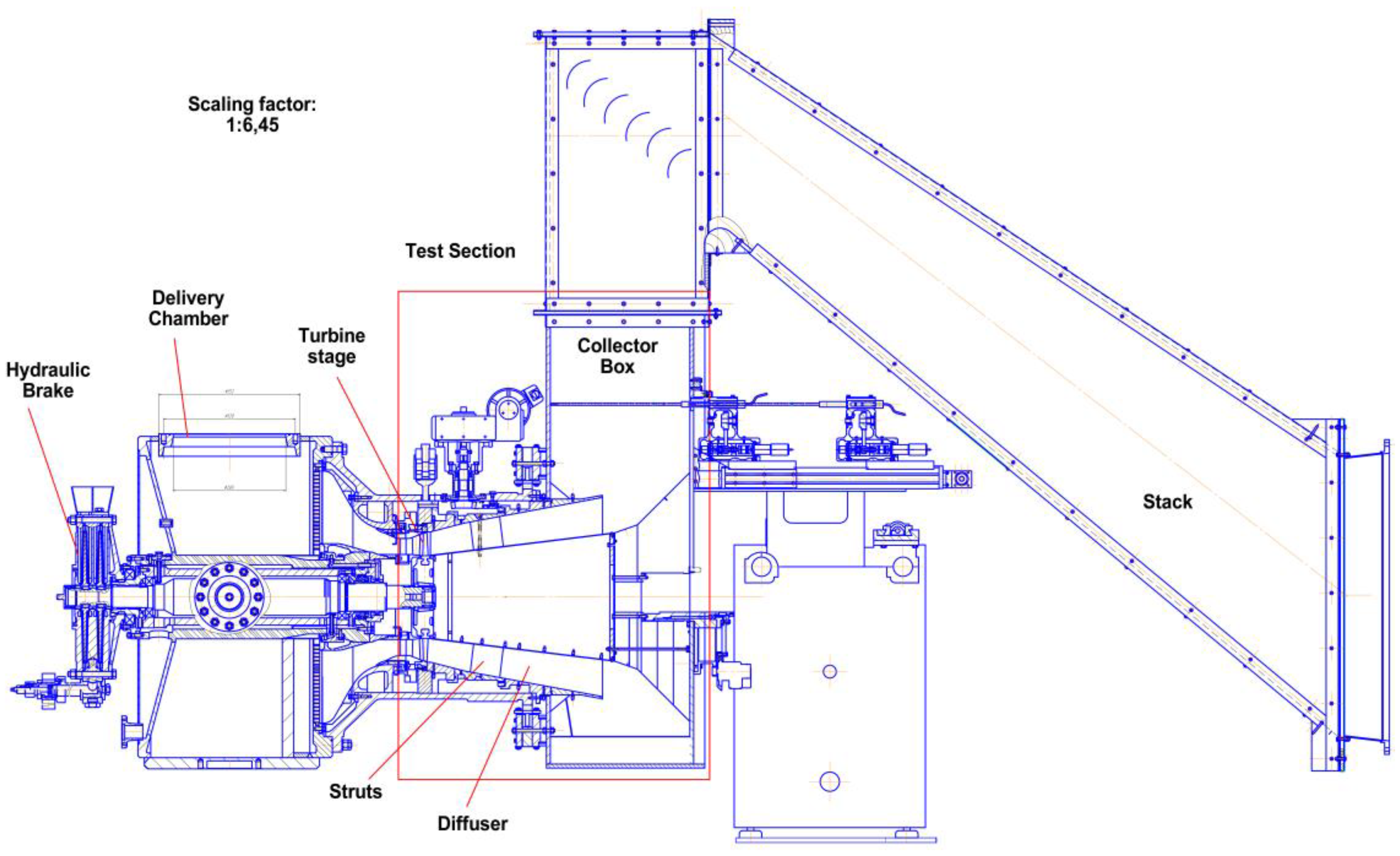
TEST FACILITY. Experimental investigations of the exhaust system “D—CB” (“Diffuser—Collector Box”) of the two-shaft gas turbine were carried out on the Test Ring ET4 in the Turbomachinery laboratory of Peter the Great St. Petersburg Polytechnic University (
Figure 1 and
Figure 2). The test ring was specially designed for aerodynamic research of exhaust (axial and/or radial) and transition ducts of the turbines. The SPbPU Test Rig ET4 is provided with a turbine wheel, shaft, and water brake. The bladed wheel is driven by the main flow of air. A caged water brake lever provides turbine wheel momentum measurement. A double cantilever rotor eliminates the union joint of the turbine rotor and hydraulic brake rotor. The rotor is inside the hydraulic brake case rolling sleeve. Bearing friction torque and air friction torque are transmitted to a hydraulic brake weighing instrument.
Three compressors provide up to 19 kg/s mass flow of air with a pressure ratio
. The compressor station capacity, which includes three compressors, is presented in
Table 1. The maximal inlet diffuser diameter is 425 mm. The maximal shaft speed is 15,000 rpm (
Table 1 and
Table 2). The maximal shaft speed is defined by the strength of the aluminum model rotor blades.
Described investigations were carried out for the axial-radial diffuser. To provide investigations of the axial annular diffuser with radial collector box, the test rig was complemented by a special diversion channel to study the exhaust duct with the nonaxisymmetric outlet, which permits to rotate of the collector box of 180 degrees around the turbine axis.
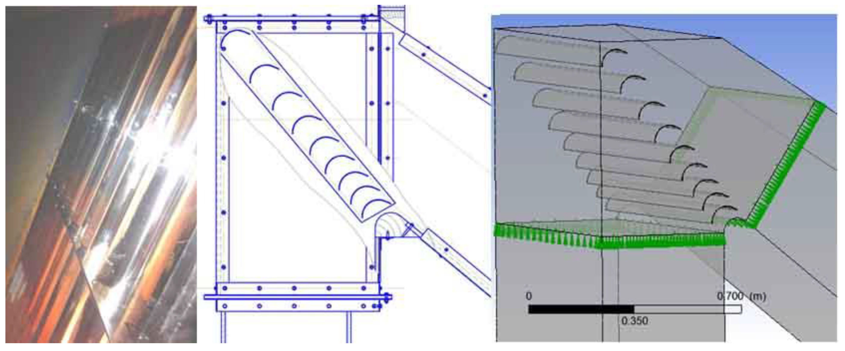
The stack is equipped with guide vanes to avoid the back influence of turning flow (
Figure 3).
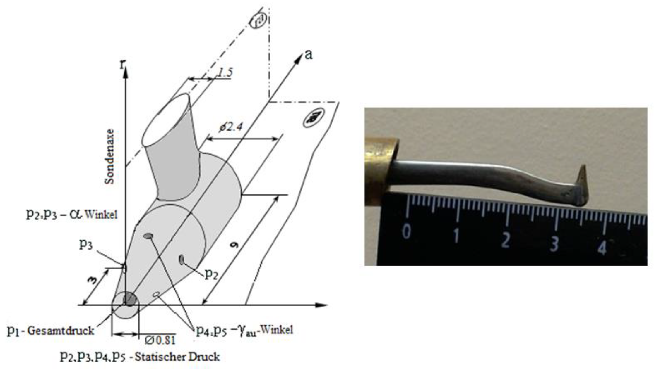
Test rig measurement system. Exhaust diffuser hub and casing walls static pressure measurements (360 points) and inlet flow fields traversing in 260 points (total pressure and temperature, static pressure, and velocity components) were carried out simultaneously. Flow traversing parameters (total pressure, static pressure, total temperature, and flow angle) were carried out with the five-channel pneumatic pressure probes. Special conical five-channel probe “3D-C” (three dimensional conical) was designed by V. Chernikov for vortex flow measurements (
Figure 4).
Probe head diameter is 2.4 mm. The sensing hole size is 0.1 mm. However, “3D-C” does not fit with a thermocouple. United Sensor five-channel probes DAT-187-24-E-22-C with Traverse units were also used (
Figure 5). The automatic coordinate measuring device allows the rotation of the probe of 360° in yaw (α) and moves it in the radial direction.
Portable pressure scanners are connected to pneumatic probes. Pressure scanners in the measuring rack are connected with pressure taps. Portable pressure scanners and the measuring rack are united on the integrated system (
Figure 6).
Measurement data and controlled parameters are processed by the “flow expert” platform.
The simultaneous traversing of the inlet and outlet flow parameters increases the accuracy of the estimation of integral characteristics of the duct, of the model turbine stage, and of the whole block. Pressure recovery coefficient, efficiency coefficient, and loss factor are calculated using the results of the traversing of 3D-flow and static pressure measurements along the exhaust duct. Simultaneously with airflow parameters measurements of the shaft speed and the force applied to the hydro brake lever are controlled and recorded.
Instrumented uncertainties are in
Table 3. Measurement uncertainties are in
Table 4 and
Table 5. Uncertainties for indirect parameters are in
Table 6.
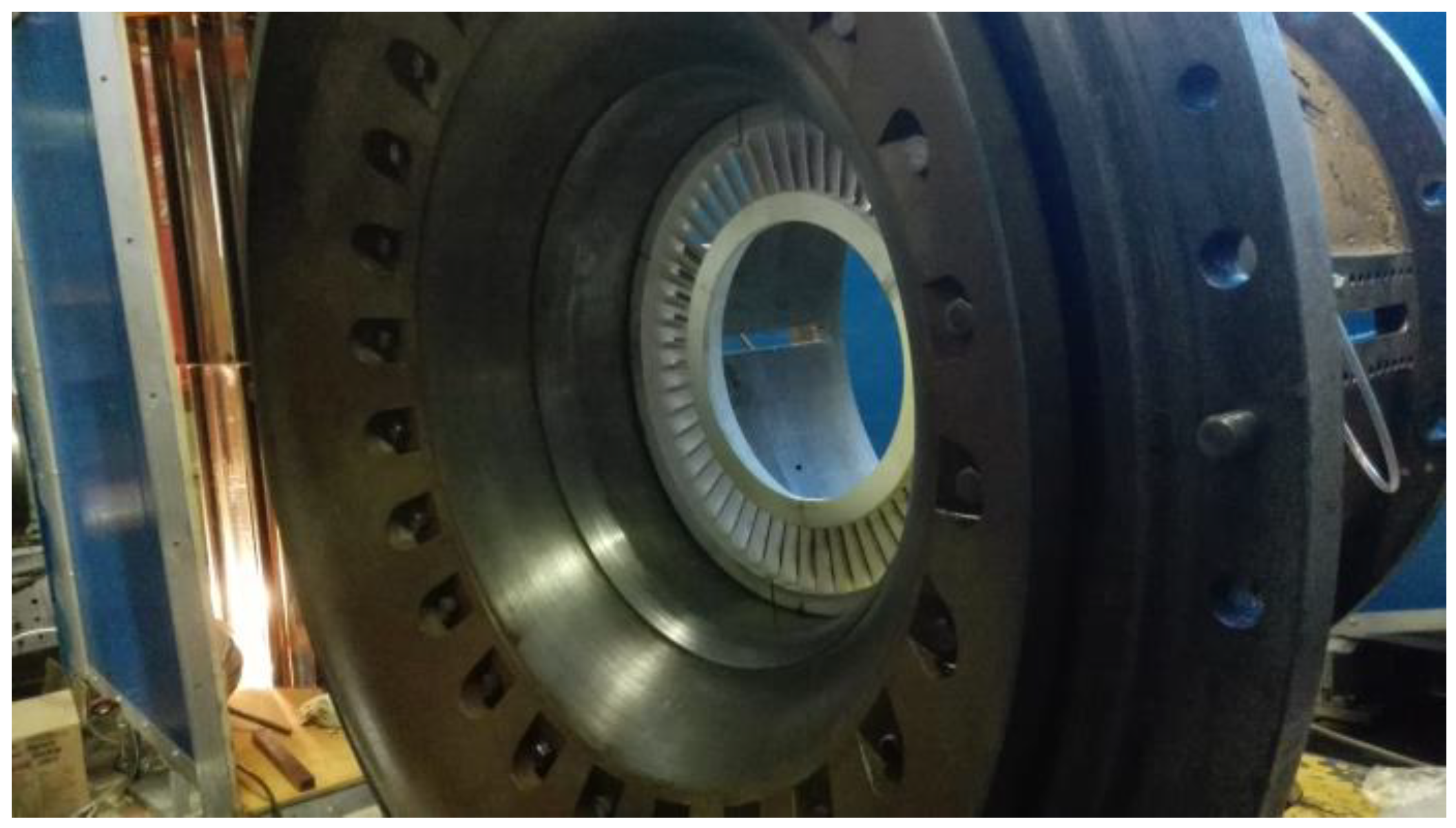
Test section instrumentation. The test section consists of the guide vanes, to provide stage inlet flow conditions without incidence angle, the turbine stage (TS) (model of the last stage of the power turbine), the exhaust diffuser (ED), and the collector box (CB). The nozzle vane ring was realized by 3D printing (
Figure 7). Blades were pressed from duralumin (to reduce blade root stress and increase the range of wheel rotation speed).
The test section is equipped with five multichannel pneumatic probes and pressure taps in the casing and hub walls (
Figure 8). Measurable data and instruments are described in
Table 3.
Flow parameters (total and static pressure, flow angle) are traversed in the radial direction with two five-channel pneumatic probes in section 2 and in sections 5-5 (one multichannel probe).
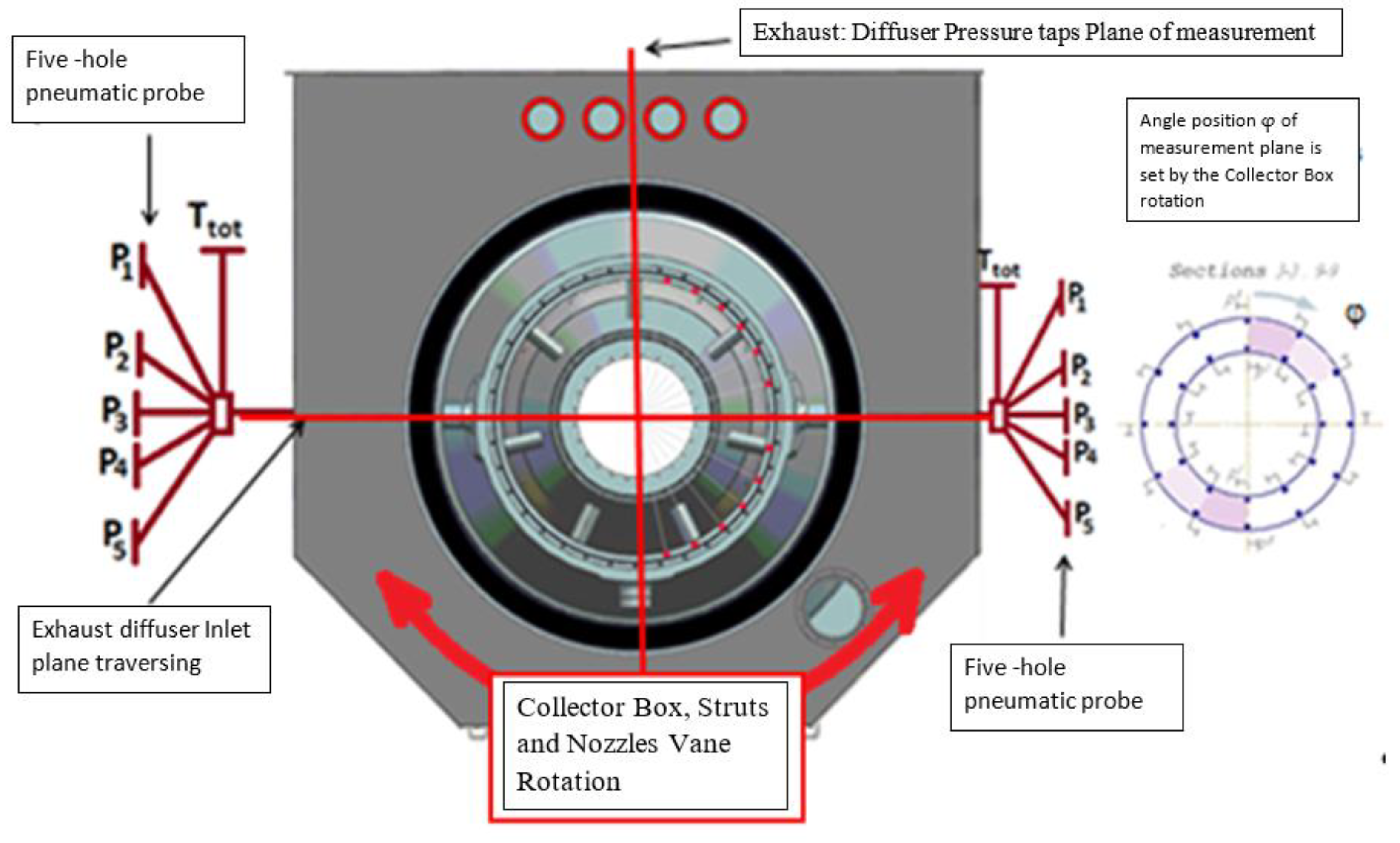
Flow at the exit of the collector box (section 10) is traversed with two five-channel pressure probes in the x and y directions in the orthogonal coordinate system with the special probe coordinate devices. The exhaust diffuser has forty points of static pressure measurement. Ten taps on the hub and ten taps on the case to the wall static pressure measurement in two lines: 0 deg. and 180 deg. Traversing equipment and pressure taps are stationary. The nozzle vane, the struts, and the collector box could be rotated around an axis (
Figure 9).
Experiment Setup. The purpose of the investigations is to estimate experimentally the Exhaust Diffuser and the Exhaust System pressure recovery coefficient. Inlet flow conditions have a significant influence on the diffuser parameters. Two operational conditions with different flow swirl angles (11,300 rev/min; 12,700 rev/min) were investigated. The investigation of the pressure recovery process is based on the method of traversing and wall static pressure measurement with taps.
where
− averaged wall static pressure in section
i = 2,…,9.
Traversing equipment and pressure taps are stationary. To obtain results of flow traversing in the circumferential and radial direction at the diffuser onlet (section 2-2) and after struts (section 5-5), collector and struts are rotated.
The exhaust diffuser has a total of forty taps. At the twelve o’clock position, ten taps are on the hub and ten taps on the case, and the same holds for the six o’clock position (ten taps are on the hub and ten taps on the case) (
Figure 9). The test rig design is capable of changing the number of measurement points in the circumferential direction. Rotating the collector box and struts section permit to change of the geometry of the test section while the instrumentation is fixed. The nonaxisymmetric collector box influences the flow conditions. Therefore, the collector box and strut’s mutual bracing have to be controlled, and the collector box and struts’ angular positions are harmonized to keep geometry uniform. As a result of the geometry modification, the flow parameters at the different circumferential points of the diffuser were measured. Twelve angular positions were measured.
Five flow parameters are measured in the traversing sections: total pressure, static pressure, pitch angle, yaw angle, and total temperature. For the diffuser inlet traversing the flow, parameters were measured in 9 points in the radial direction and 24 angular positions in the circumferential direction.
For the exhaust system exit, traversing the collector box is fixed on the twelve o’clock position. An array of collector box exit traversing are defined by an orthogonal coordinate system. The x-axis is defined as parallel to the machine axis, the y-axis parallel to the radial coordinate, and the z-axis perpendicular to the x- and y-axis. A positive yaw angle indicates a flow rotation around the machine axis in the counterclockwise direction. A positive pitch angle indicates a flow moving away from the machine axis. The 20 × 8 points of traversing and 20 pressure taps on the walls are in the section of measurement.
Investigations of the influence of nozzles (vane–blade interaction) are combined with flow parameters measurements at the exit of the collector. The pressure recovery coefficient is defined based on flow parameters traversing results in three sections and static pressure measurements, which are recorded simultaneously.
Traversing results are averaged to obtain integral parameters (
Figure 10). The mass-weighted average approach [
21] is based on the following expressions:
Mass-weighted averaged parameters:
Experimental conditions are defined based on the main criteria of similarity: kinematic similarity (flow coefficient) and criterion of compressibility (Mach number) (
Table 7).
Model mass flow rate is defined by the gas dynamic function [
21]:
Rotation speed is defined based on the flowxCoefficient
. The match of flow coefficients provides flow triangles similarity:
The red triangle in
Figure 11 is similar to the black triangle because
they have one equal angle (
). Hence,
because
.
Dynamic similarity − − Speed Coefficient, where − theoretical velocity, − Isentropic heat drop.
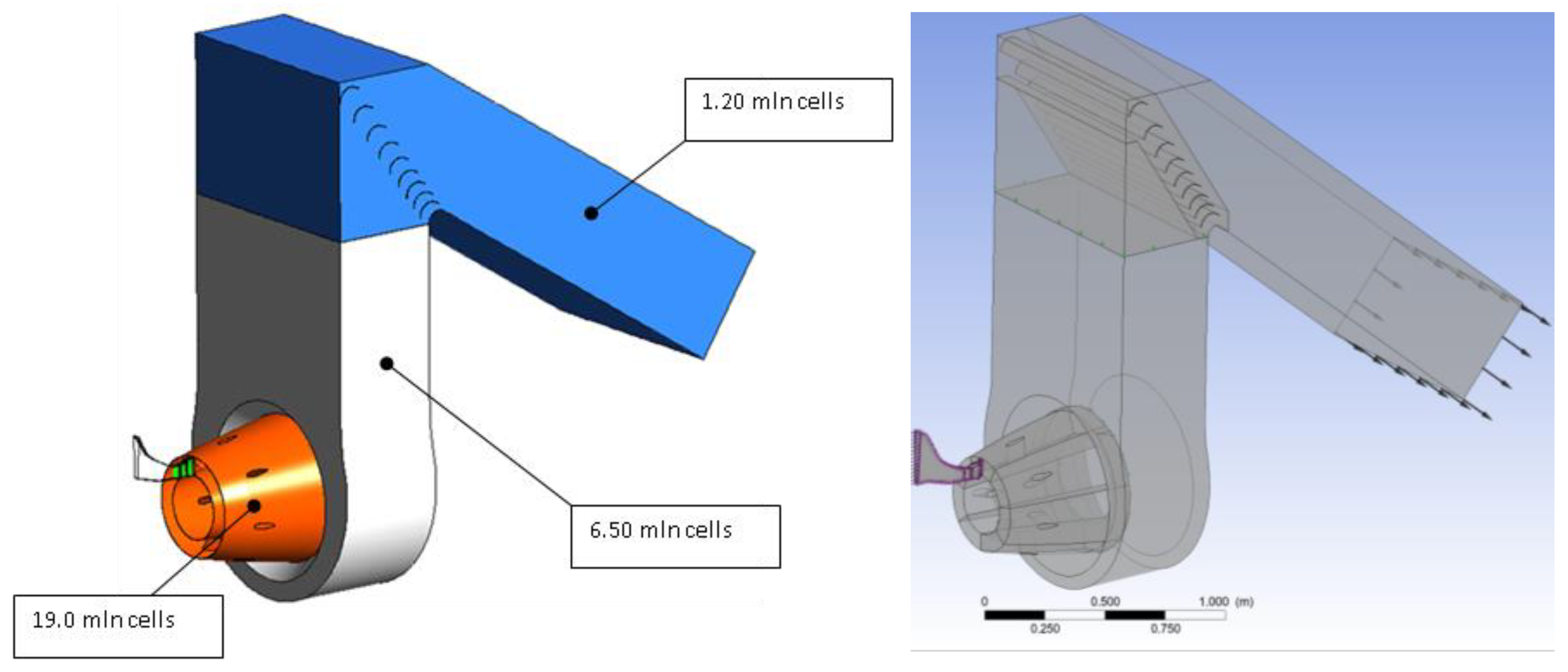
Computational domain. Experimental investigations are compared with numerical simulations. The computation domain consists of the test rig inlet contractor (test rig path flow after flow straightener), inlet guide vane, stage, exhaust diffuser with struts and collector box, and stack with turning vanes (
Figure 12) at 29.05 mln elements.
The exhaust diffuser and collector box meshes were created using mesh generator ANSYS ICEM CFD. The boundary layer height is 8 mm with 18 prismatic cells layers, the wall cells (first) layer height is 0.015 mm, and the growth ratio is 1.2. The stage, ED, and CB first-layer dimensionless height is y+ ≤ 10 according to turbulence model requirement. The maximal y+ value is on the local zone of the struts leading edge. Inlet guide vane domain, vane, and rotor blade have hexahedron mesh with a boundary layer. Blades and vane’s first layer dimensionless height is y+ < 9 (
Figure 13).
The tip clearance is 0.5 mm in agreement with the test section.
SST k-ω turbulence model and no-slip adiabatic walls were used.
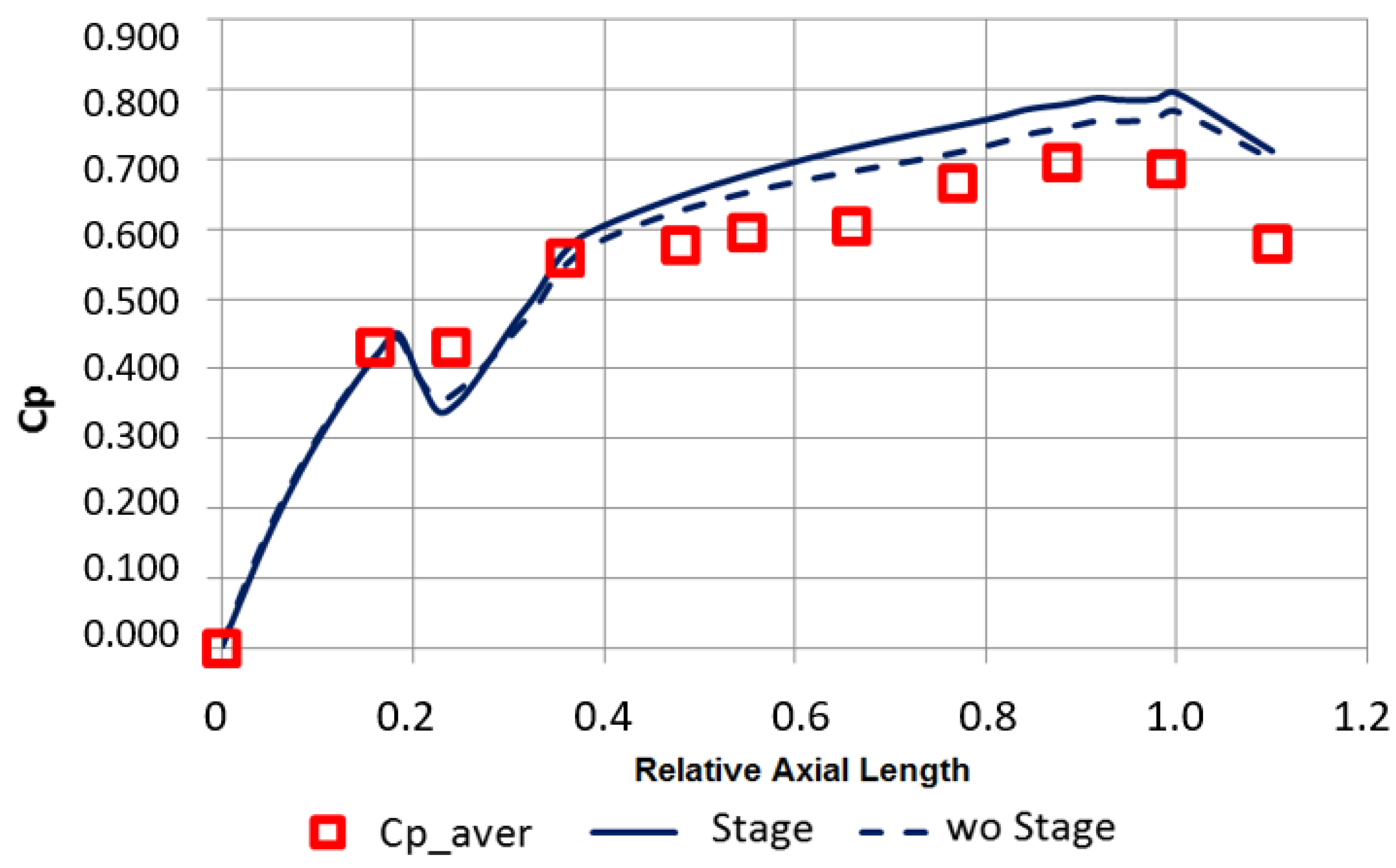
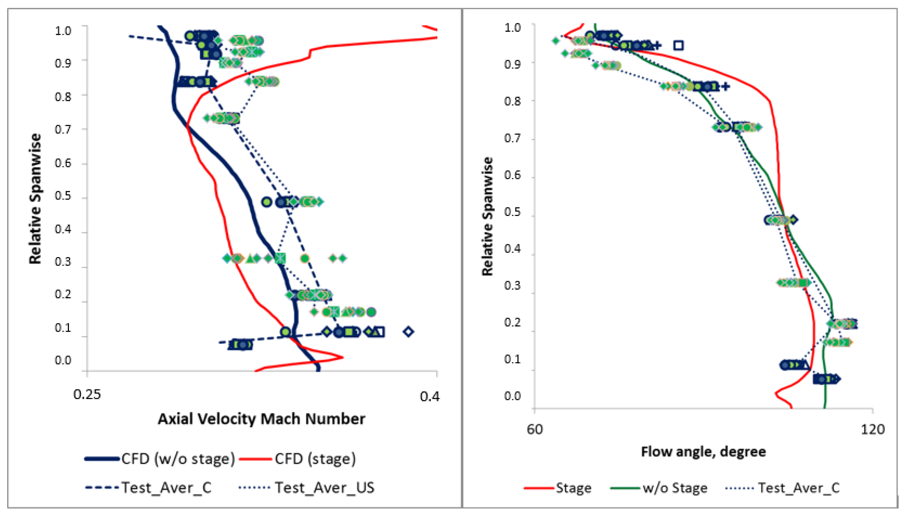
To clarify the influence of the diffuser inlet flow conditions, two cases of CFD setup are investigated as follows: whether or not the computation domain includes the turbine stage. In the case where the computation domain includes the turbine stage, the boundary conditions are defined at the inlet of supply path. If the turbine stage is excluded from the computation domain, experimental data are interpolated at the diffuser inlet.
The turbine stage with stage interface for the rotation domain is used for simulation. Flow parameters are transported through the interface with circumferential averaging.
4. Discussion
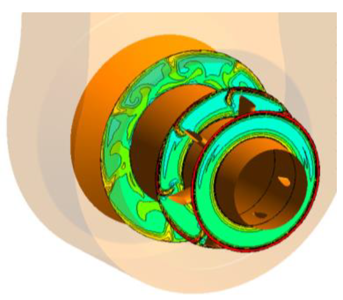
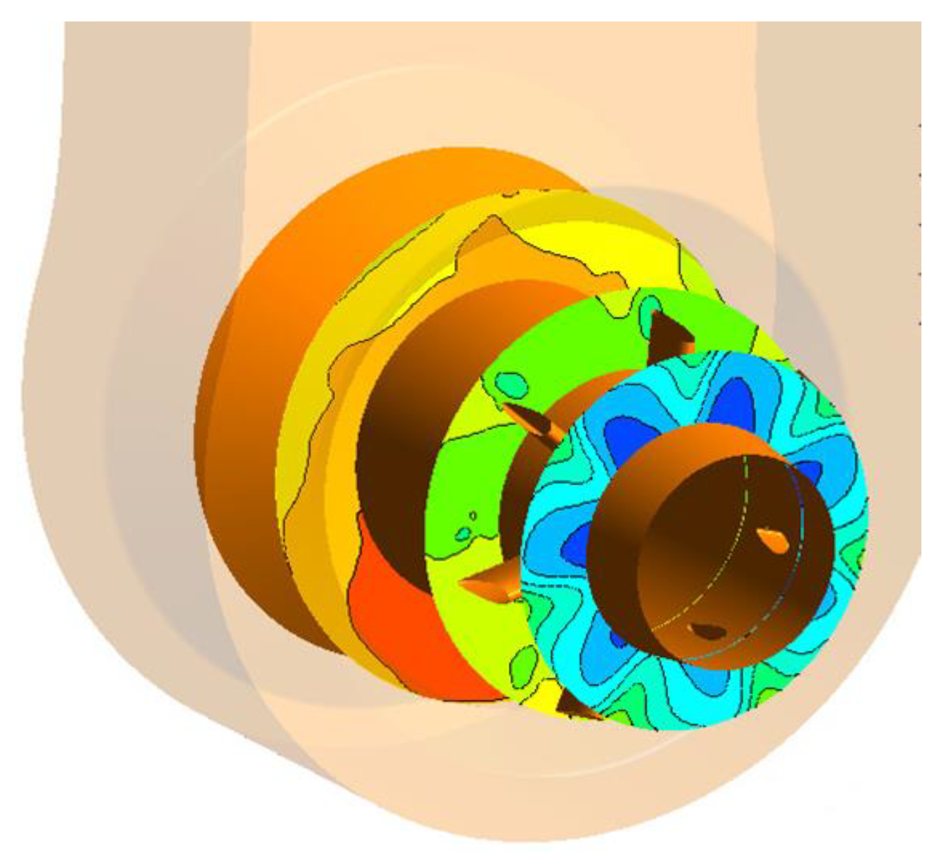
The results of this study show that the presence of struts in the exhaust diffuser generates vortexes that can affect the exhaust diffuser pressure recovery coefficient. The flow after the struts was found to have a complex structure, indicating the presence of channel vortexes. The authors suggest that the use of unsteady RANS and LES models could be a suitable method for further validation to investigate the impact of channel vortexes on the exhaust diffuser pressure recovery coefficient.
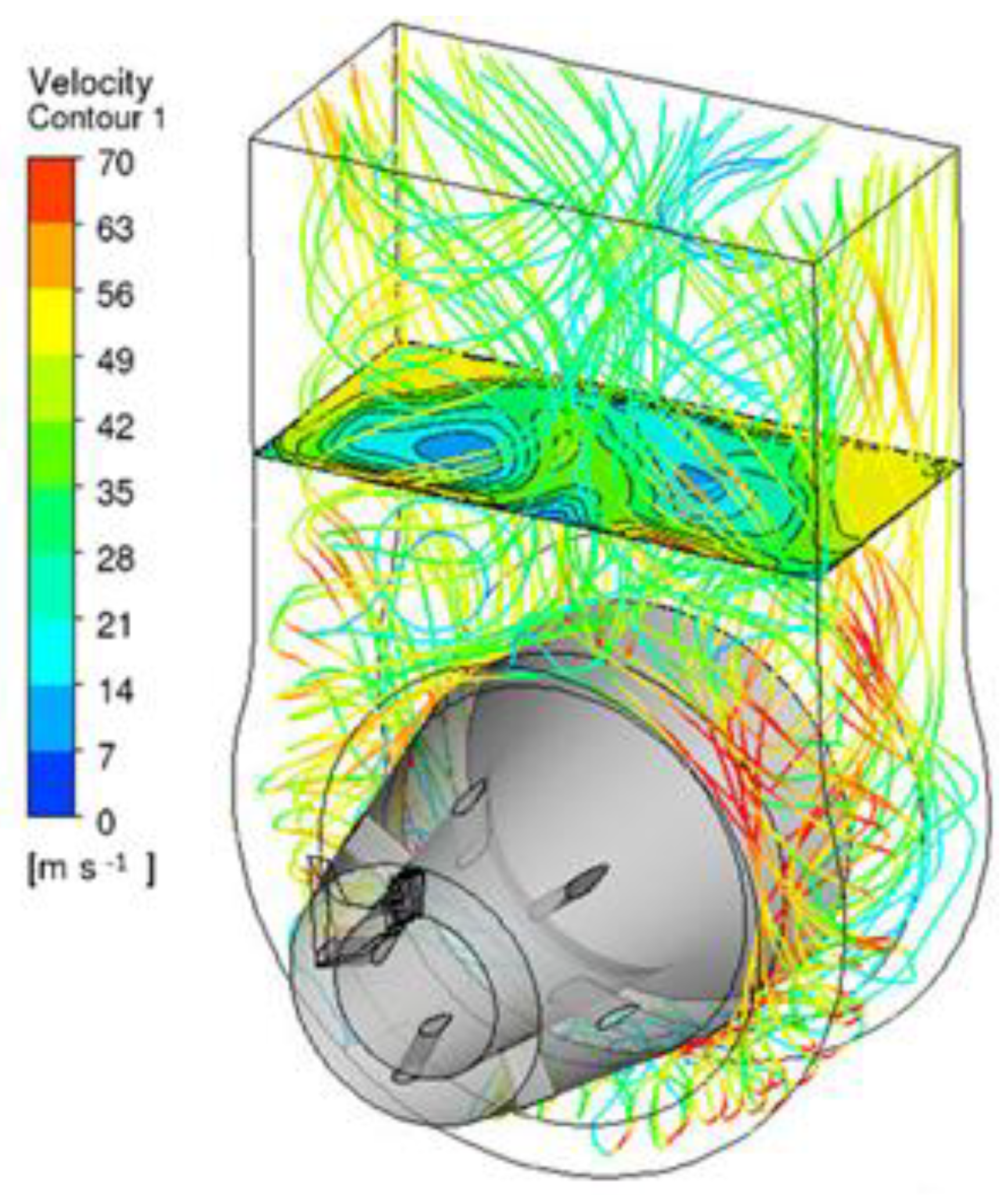
The collector box outlet was also found to have a complex non-stationary flow, with two large vortexes occurring in the central part of the channel. The vortexes from the discharge sector occupied most of the space in the channel, while the main flow distributed along the back and side walls. The CFD simulation predictions were found to match the experimental data for the reduction in pressure recovery coefficient in the diffuser discharge sector and collector box.
This study’s findings suggest that the presence of struts and the complex non-stationary flow in the collector box outlet can impact the performance of the exhaust system of two-shaft gas turbines. The potential influence on the diffuser flow induced by a one-sided flow diversion with the help of a collector box leads to different angles of attack on the power struts along the circumference and, consequently, to different areas of vortex wakes behind them. As is known, the vortex wakes behind the struts are the main sources of losses in the exhaust diffuser. Further research is needed to investigate the impact of these factors on the efficiency and thermal performance of gas turbines. The integrated approach of combining experimental and numerical methods used in this study can provide a detailed and reliable flow picture of the exhaust system, which can be used to optimize the design of two-shaft gas turbine exhaust systems and improve their efficiency.
In this investigation, the aerodynamic performance of the exhaust system of a two-shaft gas turbine was examined experimentally and numerically. The focus of this inquiry was on the “Turbine Stage-Diffuser—Collector Box” system, and the aim was to analyze the impact of inlet conditions and geometry particulars on the efficiency of the exhaust system. The experiments were carried out on the Test Ring ET4 at the Peter the Great St.-Petersburg Polytechnic University, which was equipped with a special diversion channel to evaluate the non-axisymmetric outlet of the exhaust duct. To measure flow traversing parameters, five-channel pneumatic pressure probes were used, and numerical simulations were conducted using CFX 15.0. The RANS equations were closed with the SST (k-ω) turbulence model.
Overall, the study’s findings provide a foundation for further research on the optimization of the exhaust system of two-shaft gas turbines, which can improve their thermal efficiency and reduce energy losses. The integrated approach of combining experimental and numerical methods can provide a detailed and reliable flow picture, which can be used for future research in this area.
To minimize the impact of vortexes generated by the struts on the flow structure in the collector box and to reduce the energy losses in the outlet duct, it is necessary to clarify the flow structure downstream of the struts. This is possible by using more proper approach for study complex vortex structure of the turbulent flow for example-LES or DES method.
5. Conclusions
This investigation concludes that the RANS SST model predicts the flow in the diffuser before the struts accurately. However, during the downstream of the struts, the CFD results over-predicted the exhaust diffuser pressure recovery coefficient by 14% due to the complex vortex structure of the turbulent flow, which the Averaged Navier–Stokes equations did not resolve. The examination highlights the importance of considering the last stage of the turbine, diffuser, and collector box as an integrated system when investigating the aerodynamics of exhaust ducts.
The results of this exploration can be utilized to optimize the design of the exhaust system of two-shaft gas turbines and enhance their thermal efficiency. The integrated approach of combining experimental and numerical methods can provide a detailed and reliable flow picture, and it can be used for future research in this area. Therefore, this inquiry has made a significant contribution to understanding the aerodynamics of exhaust ducts in two-shaft gas turbines, and further research in this field is recommended.
This study’s findings suggest that the presence of struts and the complex non-stationary flow in the collector box outlet can impact the performance of the exhaust system of two-shaft gas turbines. Therefore, further research is necessary to investigate the impact of these factors on the efficiency and thermal performance of gas turbines.
Moreover, the effect of different inlet conditions such as varying inlet velocity profiles and turbulence intensities on the exhaust diffuser’s performance and efficiency can be investigated in future research. The impact of operating conditions such as the turbine load on the exhaust system’s performance and efficiency can also be studied to optimize the design of the exhaust system for different operating conditions.


