

Steady-State Load Flow Model of DFIG Wind Turbine Based on Generator Power Loss Calculation

Abstract
1. Introduction
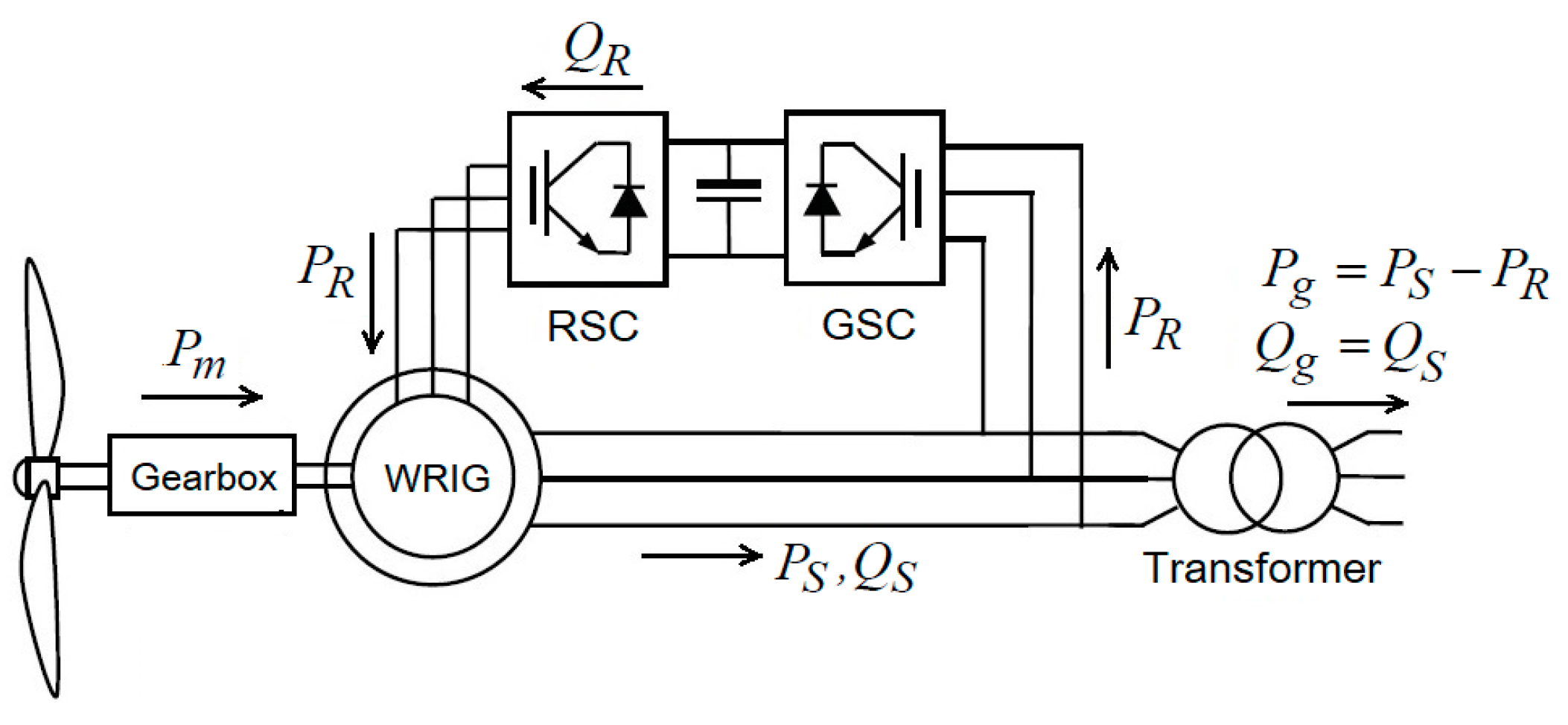
2. DFIG-Based Wind Turbine
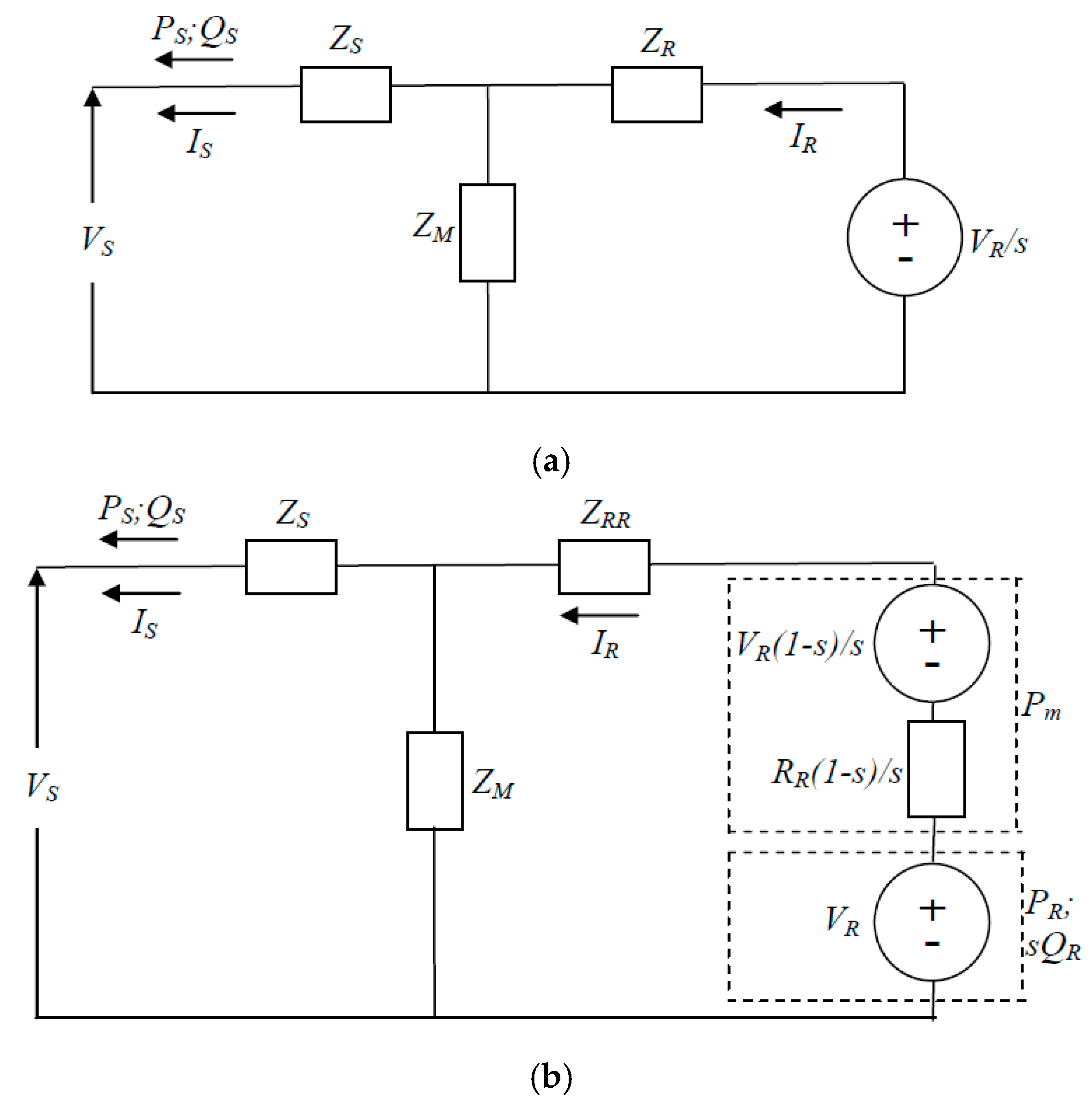
2.1. DFIG Configuration and Equivalent Circuit
2.2. DFIG Power and WRIG Loss Formulas
2.3. DFIG Steady-State Load Flow Model
3. Case Study
3.1. WPP Data
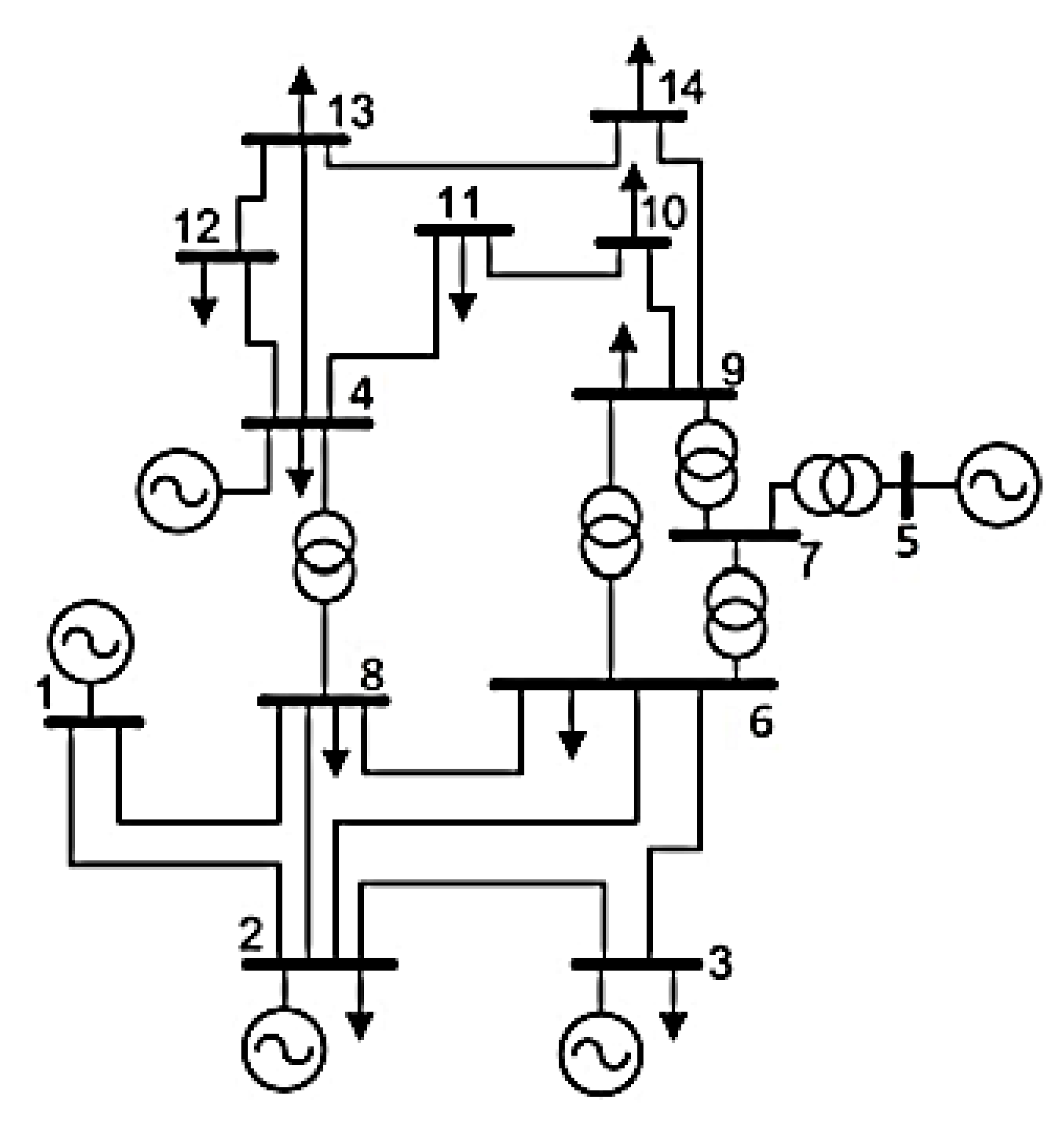
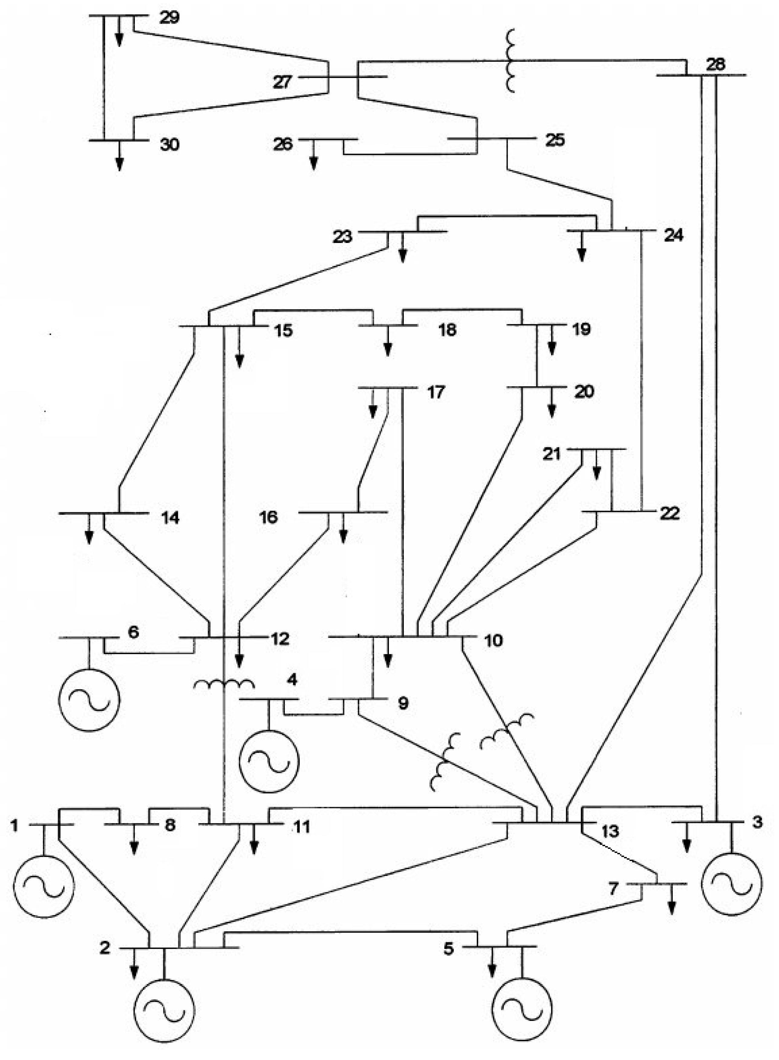
3.2. Test Systems
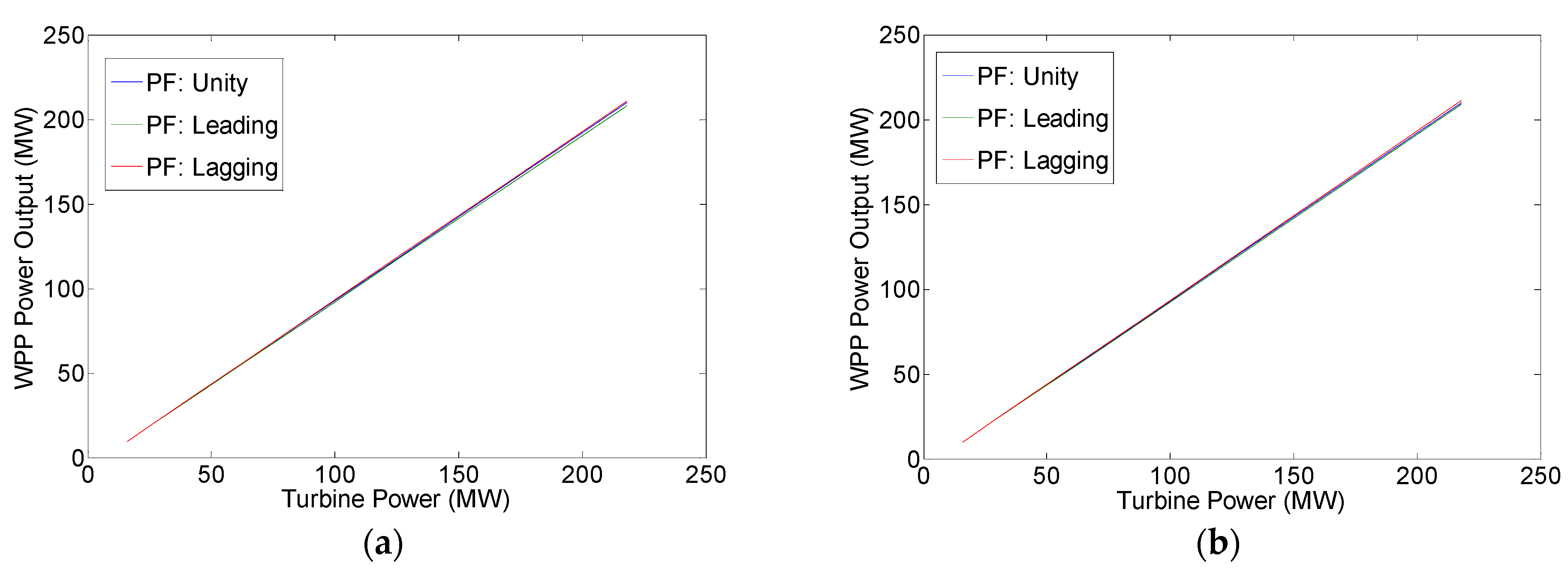
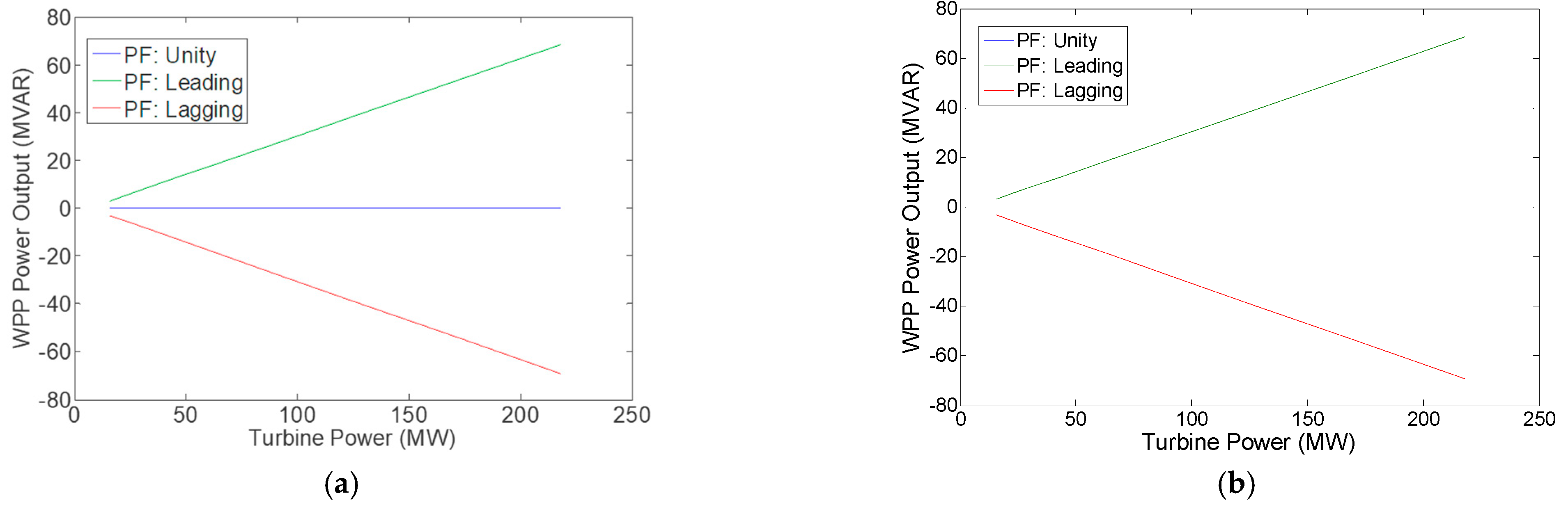
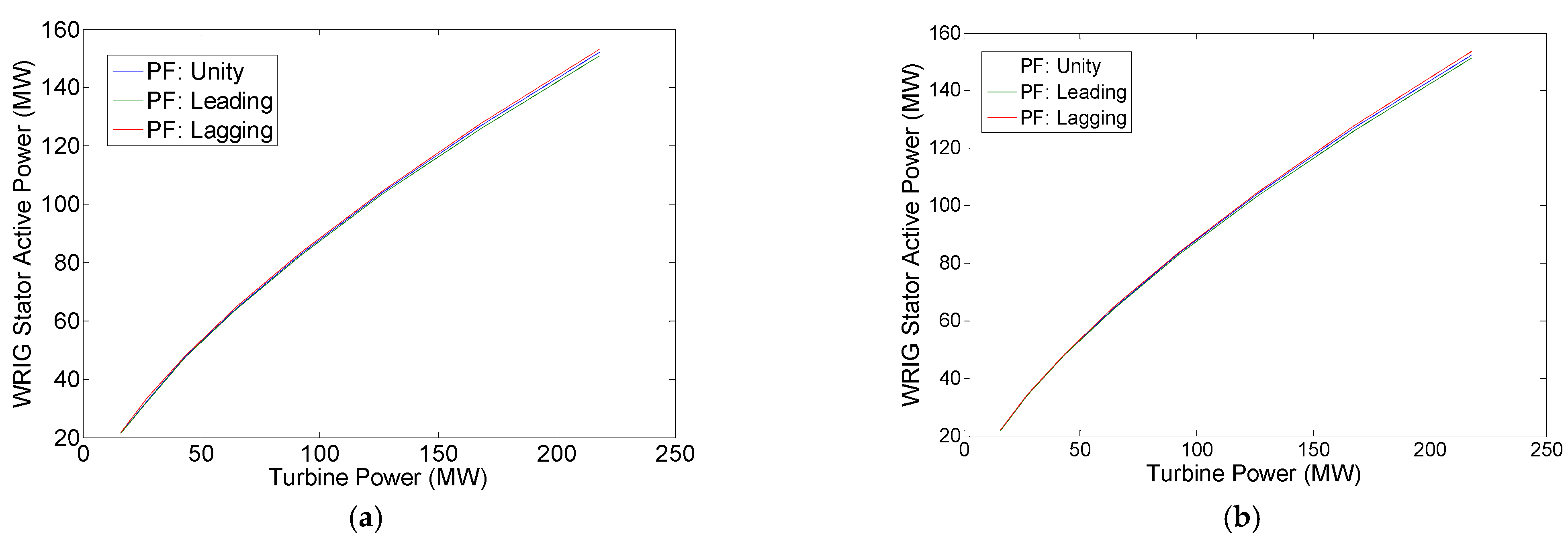
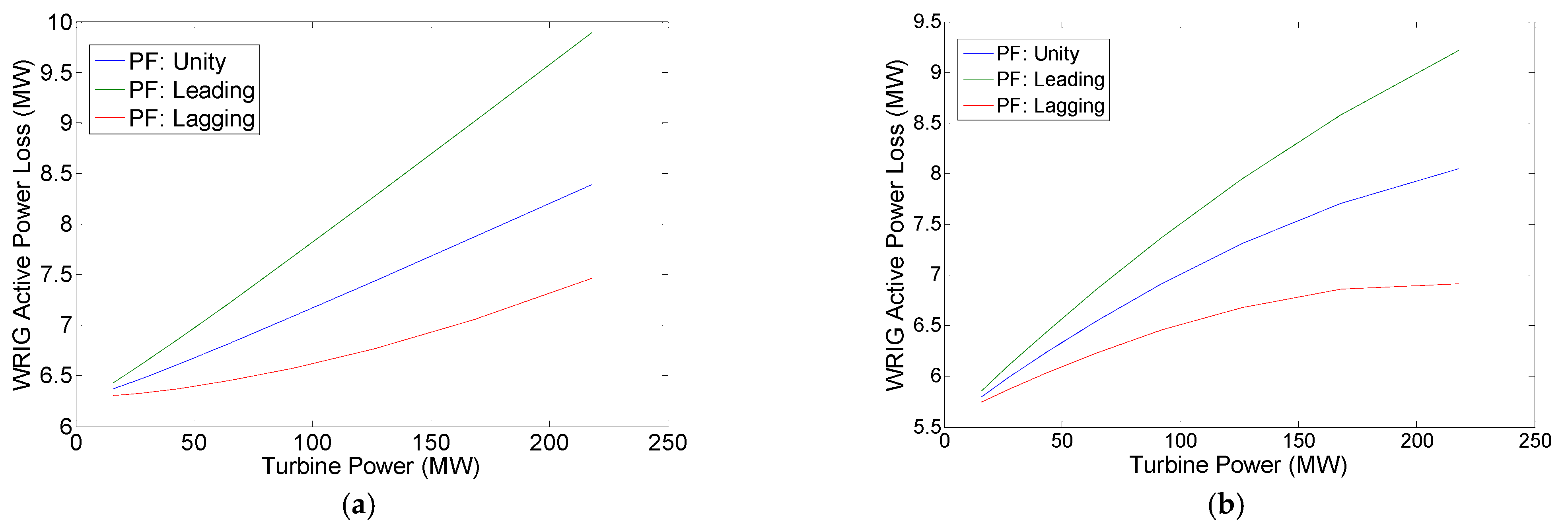
3.3. Results and Discussion
4. Conclusions
Author Contributions
Funding
Data Availability Statement
Conflicts of Interest
References
- Haque, M.H. Evaluation of power flow solutions with fixed speed wind turbine generating systems. Energy Convers. Manag. 2014, 79, 511–518. [Google Scholar] [CrossRef]
- Haque, M.H. Incorporation of fixed speed wind turbine generators in load flow analysis of distribution systems. Int. J. Renew. Energy Technol. 2015, 6, 317–324. [Google Scholar] [CrossRef]
- Wang, J.; Huang, C.; Zobaa, A.F. Multiple-node models of asynchronous wind turbines in wind farms for load flow analysis. Electr. Power Compon. Syst. 2015, 44, 135–141. [Google Scholar] [CrossRef]
- Feijoo, A.; Villanueva, D. A PQ model for asynchronous machines based on rotor voltage calculation. IEEE Trans. Energy Convers. 2016, 31, 813–814, Correction in IEEE Trans. Energy Convers. 2016, 31, 1228. [Google Scholar] [CrossRef]
- Ozturk, O.; Balci, M.E.; Hocaoglu, M.H. A new wind turbine generating system model for balanced and unbalanced distribution systems load flow analysis. Appl. Sci. 2018, 8, 502. [Google Scholar]
- Dadhania, A.; Venkatesh, B.; Nassif, A.B.; Sood, V.K. Modeling of doubly fed induction generators for distribution system power flow analysis. Electr. Power Energy Syst. 2013, 53, 576–583. [Google Scholar] [CrossRef]
- Ju, Y.; Ge, F.; Wu, W.; Lin, Y.; Wang, J. Three-phase steady-state model of DFIG considering various rotor speeds. IEEE Access 2016, 4, 9479–9948. [Google Scholar] [CrossRef]
- Kumar, V.S.S.; Thukaram, D. Accurate modeling of doubly fed induction based wind farms in load flow analysis. Electr. Power Syst. Res. 2018, 15, 363–371. [Google Scholar]
- Li, S. Power flow modeling to doubly-fed induction generators (DFIGs) under power regulation. IEEE Trans. Power Syst. 2013, 28, 3292–3301. [Google Scholar] [CrossRef]
- Anirudh, C.V.S.; Seshadri, S.K.V. Enhanced modeling of doubly fed induction generator in load flow analysis of distribution systems. IET Renew. Power Gener. 2021, 15, 980–989. [Google Scholar]
- Gianto, R. Steady state model of DFIG-based wind power plant for load flow analysis. IET Renew. Power Gener. 2021, 15, 1724–1735. [Google Scholar] [CrossRef]
- Gianto, R. Constant voltage model of DFIG-based variable speed wind turbine for load flow analysis. Energies 2021, 14, 8549. [Google Scholar] [CrossRef]
- Gianto, R. Constant power factor model of DFIG-based wind turbine for steady state load flow analysis. Energies 2022, 15, 6077. [Google Scholar] [CrossRef]
- Anaya-Lara, O.; Jenkins, N.; Ekanayake, J.B.; Cartwright, P.; Hughes, M. Wind Energy Generation: Modelling and Control; John Wiley & Sons, Ltd.: Chichester, UK, 2009. [Google Scholar]
- Akhmatov, V. Induction Generators for Wind Power; Multi-Science Publishing Co., Ltd.: Brentwood, UK, 2007. [Google Scholar]
- Boldea, I. Variable Speed Generators; Taylor & Francis Group LLC.: Roca Baton, FL, USA, 2005. [Google Scholar]
- Fox, B.; Flynn, B.; Bryans, L.; Jenkins, J. Wind Power Integration: Connection and System Operational Aspects; The Institution of Engineering and Technology: Stevenage Herts, UK, 2007. [Google Scholar]
- Patel, M.R. Wind and Solar Power Systems; CRC Press LLC.: Boca Raton, FL, USA, 1999. [Google Scholar]
- Pai, M.A. Computer Techniques in Power System Analysis; Tata McGraw-Hill Publishing Co., Ltd.: New Delhi, India, 1984. [Google Scholar]


| Bus | Equation(s) | Knowns | Unknowns |
|---|---|---|---|
| Slack | (14) | |V| and δ = 0° | PG and QG |
| PV | (14) | PG and |V| | δ and QG |
| PQ | (14) | PG = QG = 0 | |V| and δ |
| WPP | (13) and (14) | ϕ, s, and Pm | |V| = |VS|, δ = δS, PG = Pg, QR, Re(VR) and Im(VR) |
| Line | Sending Bus | Receiving Bus | Series Impedance |
|---|---|---|---|
| 1 | 1 | 2 | 0.0192 + j0.0575 |
| 2 | 1 | 8 | 0.0452 + j0.1852 |
| 3 | 2 | 11 | 0.0570 + j0.1737 |
| 4 | 8 | 11 | 0.0132 + j0.0379 |
| 5 | 2 | 5 | 0.0472 + j0.1983 |
| 6 | 2 | 13 | 0.0581 + j0.1763 |
| 7 | 11 | 13 | 0.0119 + j0.0414 |
| 8 | 5 | 7 | 0.0460 + j0.1160 |
| 9 | 7 | 13 | 0.0267 + j0.0820 |
| 10 | 3 | 13 | 0.0120 + j0.0420 |
| 11 | 9 | 13 | j0.2080 |
| 12 | 10 | 13 | j0.5560 |
| 13 | 4 | 9 | j0.2080 |
| 14 | 9 | 10 | j0.1100 |
| 15 | 11 | 12 | j0.2560 |
| 16 | 6 | 12 | j0.1400 |
| 17 | 12 | 14 | 0.1231 + j0.2559 |
| 18 | 12 | 15 | 0.0662 + j0.1304 |
| 19 | 12 | 16 | 0.0945 + j0.1987 |
| 20 | 14 | 15 | 0.2210 + j0.1997 |
| 21 | 16 | 17 | 0.0824 + j0.1932 |
| 22 | 15 | 18 | 0.1073 + j0.2185 |
| 23 | 18 | 19 | 0.0639 + j0.1292 |
| 24 | 19 | 20 | 0.0340 + j0.0680 |
| 25 | 10 | 20 | 0.0936 + j0.2090 |
| 26 | 10 | 17 | 0.0324 + j0.0845 |
| 27 | 10 | 21 | 0.0348 + j0.0749 |
| 28 | 10 | 22 | 0.0727 + j0.1499 |
| 29 | 21 | 22 | 0.0116 + j0.0236 |
| 30 | 15 | 23 | 0.1000 + j0.2020 |
| 31 | 22 | 24 | 0.1150 + j0.1790 |
| 32 | 23 | 24 | 0.1320 + j0.2700 |
| 33 | 24 | 25 | 0.1885 + j0.3292 |
| 34 | 25 | 26 | 0.2544 + j0.3800 |
| 35 | 25 | 27 | 0.1093 + j0.2087 |
| 36 | 27 | 28 | j0.3960 |
| 37 | 27 | 29 | 0.2198 + j0.4153 |
| 38 | 27 | 30 | 0.3202 + j0.6027 |
| 39 | 29 | 30 | 0.2399 + j0.4533 |
| 40 | 3 | 28 | 0.0636 + j0.2000 |
| 41 | 13 | 28 | 0.0169 + j0.0599 |
| Bus | |V| | δ | Generation | Load | Note |
|---|---|---|---|---|---|
| 1 | 1.0500 | 0 | - | 0 | Slack |
| 2 | 1.0338 | - | 0.5756 + j- | 0.217 + j0.127 | PV |
| 3 | 1.0230 | - | 0.3500 + j- | 0.300 + j0.300 | PV |
| 4 | 1.0913 | - | 0.1793 + j- | 0 | PV |
| 5 | 1.0058 | - | 0.2456 + j- | 0.942 + j0.190 | PV |
| 6 | 1.0883 | - | 0.1691 + j- | 0 | PV |
| 7 | - | - | 0 | 0.228 + j0.109 | PQ |
| 8 | - | - | 0 | 0.024 + j0.012 | PQ |
| 9 | - | - | 0 | 0 | PQ |
| 10 | - | - | 0 | 0.058 + j0.020 | PQ |
| 11 | - | - | 0 | 0.076 + j0.016 | PQ |
| 12 | - | - | 0 | 0.112 + j0.075 | PQ |
| 13 | - | - | 0 | 0 | PQ |
| 14 | - | - | 0 | 0.062 + j0.016 | PQ |
| 15 | - | - | 0 | 0.082 + j0.025 | PQ |
| 16 | - | - | 0 | 0.035 + j0.018 | PQ |
| 17 | - | - | 0 | 0.090 + j0.058 | PQ |
| 18 | - | - | 0 | 0.032 + j0.009 | PQ |
| 19 | - | - | 0 | 0.095 + j0.034 | PQ |
| 20 | - | - | 0 | 0.022 + j0.007 | PQ |
| 21 | - | - | 0 | 0.175 + j0.112 | PQ |
| 22 | - | - | 0 | 0 | PQ |
| 23 | - | - | 0 | 0.032 + j0.016 | PQ |
| 24 | - | - | 0 | 0.087 + j0.067 | PQ |
| 25 | - | - | 0 | 0 | PQ |
| 26 | - | - | 0 | 0.035 + j0.023 | PQ |
| 27 | - | - | 0 | 0 | PQ |
| 28 | - | - | 0 | 0 | PQ |
| 29 | - | - | 0 | 0.024 + j0.009 | PQ |
| 30 | - | - | 0 | 0.106 + j0.019 | PQ |
| System | Total Load (MW; MVAr) | WPP Location |
|---|---|---|
| IEEE 14-bus | 897; 243.9 | Bus 14 |
| IEEE 30-bus | 850.2; 378.6 | Bus 30 |
| ΣPm (MW) | Pg (MW) | PS (MW) | Qg = QS (MVAR) | PR (MW) | PLOSS (MW) | QLOSS (MVAR) |
|---|---|---|---|---|---|---|
| 15.78 | 9.4127 | 21.4955 | 0 | 12.0828 | 6.3673 | 63.6728 |
| 27.27 | 20.8045 | 32.8212 | 0 | 12.0167 | 6.4655 | 64.6551 |
| 43.30 | 36.6883 | 47.9329 | 0 | 11.2446 | 6.6117 | 66.1171 |
| 64.63 | 57.8139 | 64.4185 | 0 | 6.6046 | 6.8161 | 68.1608 |
| 92.02 | 84.9318 | 83.0831 | 0 | −1.8487 | 7.0882 | 70.8821 |
| 126.23 | 118.7934 | 103.9265 | 0 | −14.8669 | 7.4366 | 74.3658 |
| 168.01 | 160.1414 | 126.9522 | 0 | −33.1892 | 7.8686 | 78.6861 |
| 218.12 | 209.7292 | 152.1444 | 0 | −57.5848 | 8.3908 | 83.9077 |
| ΣPm (pu) | Voltage (pu) | G1 to G5 Outputs | Line Losses | ||
|---|---|---|---|---|---|
| MW | MVAR | MW | MVAR | ||
| 15.78 | 1.0160 | 941.7797 | 479.5449 | 54.1924 | 235.6449 |
| 27.27 | 1.0196 | 928.6547 | 470.9905 | 52.4592 | 227.0905 |
| 43.30 | 1.0243 | 910.5415 | 459.8925 | 50.2298 | 215.9925 |
| 64.63 | 1.0301 | 886.7778 | 446.5797 | 47.5917 | 202.6797 |
| 92.02 | 1.0368 | 856.8002 | 431.8180 | 44.7320 | 187.9180 |
| 126.23 | 1.0440 | 820.1648 | 416.8994 | 41.9582 | 172.9994 |
| 168.01 | 1.0512 | 776.5829 | 403.7411 | 39.7243 | 159.8411 |
| 218.12 | 1.0575 | 725.9341 | 395.0049 | 38.6634 | 151.1049 |
| ΣPm (MW) | Pg (MW) | PS (MW) | Qg = QS (MVAR) | PR (MW) | PLOSS (MW) | QLOSS (MVAR) |
|---|---|---|---|---|---|---|
| 15.78 | 9.3484 | 21.4447 | 3.0727 | 12.0962 | 6.4316 | 64.3156 |
| 27.27 | 20.6617 | 32.5085 | 6.7912 | 11.8469 | 6.6083 | 66.0830 |
| 43.30 | 36.4350 | 47.7337 | 11.9756 | 11.2987 | 6.8650 | 68.6499 |
| 64.63 | 57.4122 | 64.1035 | 18.8705 | 6.6913 | 7.2178 | 72.1783 |
| 92.02 | 84.3374 | 82.6185 | 27.7203 | −1.7189 | 7.6826 | 76.8265 |
| 126.23 | 117.9556 | 103.2733 | 38.7701 | −14.6823 | 8.2744 | 82.7441 |
| 168.01 | 159.0028 | 126.0661 | 52.2617 | −32.9368 | 9.0072 | 90.0716 |
| 218.12 | 208.2259 | 150.9748 | 68.4405 | −57.2511 | 9.8941 | 98.9412 |
| ΣPm (pu) | Voltage (pu) | G1 to G5 Outputs | Line Losses | ||
|---|---|---|---|---|---|
| MW | MVAR | MW | MVAR | ||
| 15.78 | 1.0192 | 941.7856 | 476.2581 | 54.1341 | 235.4308 |
| 27.27 | 1.0265 | 928.6796 | 463.7667 | 52.3413 | 226.6579 |
| 43.30 | 1.0364 | 910.6097 | 447.2361 | 50.0447 | 215.3117 |
| 64.63 | 1.0489 | 886.9239 | 426.7644 | 47.3361 | 201.7349 |
| 92.02 | 1.0641 | 857.0613 | 402.8550 | 44.3987 | 186.6753 |
| 126.23 | 1.0818 | 820.5608 | 376.4609 | 41.5164 | 171.3310 |
| 168.01 | 1.1016 | 777.0774 | 349.0208 | 39.0802 | 157.3825 |
| 218.12 | 1.1232 | 726.3667 | 322.4684 | 37.5925 | 147.0090 |
| ΣPm (MW) | Pg (MW) | PS (MW) | Qg = QS (MVAR) | PR (MW) | PLOSS (MW) | QLOSS (MVAR) |
|---|---|---|---|---|---|---|
| 15.78 | 9.4768 | 21.5466 | −3.1149 | 12.0698 | 6.3032 | 63.0324 |
| 27.27 | 20.9437 | 33.7330 | −6.8838 | 12.7893 | 6.3263 | 63.2634 |
| 43.30 | 36.9277 | 48.1273 | −12.1376 | 11.1996 | 6.3723 | 63.7228 |
| 64.63 | 58.1782 | 64.7191 | −19.1222 | 6.5409 | 6.4518 | 64.5183 |
| 92.02 | 85.4413 | 83.5136 | −28.0832 | −1.9278 | 6.5787 | 65.7866 |
| 126.23 | 119.4594 | 104.5087 | −39.2644 | −14.9507 | 6.7706 | 67.7056 |
| 168.01 | 160.9575 | 127.7034 | −52.9042 | −33.2541 | 7.0525 | 70.5249 |
| 218.12 | 210.6572 | 153.0724 | −69.2397 | −57.5848 | 7.4628 | 74.6282 |
| ΣPm (pu) | Voltage (pu) | G1 to G5 Outputs | Line Losses | ||
|---|---|---|---|---|---|
| MW | MVAR | MW | MVAR | ||
| 15.78 | 1.0128 | 941.7820 | 482.9034 | 54.2587 | 235.8885 |
| 27.27 | 1.0125 | 928.6695 | 478.4409 | 52.6131 | 227.6571 |
| 43.30 | 1.0118 | 910.5955 | 473.1122 | 50.5232 | 217.0747 |
| 64.63 | 1.0103 | 886.9325 | 467.6194 | 48.1106 | 204.5972 |
| 92.02 | 1.0074 | 857.1856 | 463.2116 | 45.6270 | 191.2284 |
| 126.23 | 1.0025 | 821.0420 | 461.8678 | 43.5014 | 178.7034 |
| 168.01 | 0.9940 | 778.4596 | 466.5709 | 42.4171 | 169.7667 |
| 218.12 | 0.9801 | 729.7969 | 479.8147 | 41.4541 | 168.6751 |
| ΣPm (MW) | Pg (MW) | PS (MW) | Qg = QS (MVAR) | PR (MW) | PLOSS (MW) | QLOSS (MVAR) |
|---|---|---|---|---|---|---|
| 15.78 | 9.9799 | 22.0540 | 0 | 12.0741 | 5.8001 | 58.0014 |
| 27.27 | 21.2845 | 34.0960 | 0 | 12.8115 | 5.9855 | 59.8548 |
| 43.30 | 37.0649 | 48.3081 | 0 | 11.2432 | 6.2351 | 62.3509 |
| 64.63 | 58.0831 | 64.6896 | 0 | 6.6065 | 6.5469 | 65.4688 |
| 92.02 | 85.1089 | 83.2642 | 0 | −1.8447 | 6.9111 | 69.1115 |
| 126.23 | 118.9212 | 104.0600 | 0 | −14.8612 | 7.3088 | 73.0881 |
| 168.01 | 160.3025 | 127.1258 | 0 | −33.1767 | 7.7075 | 77.0748 |
| 218.12 | 210.0714 | 152.5323 | 0 | −57.5391 | 8.0486 | 80.4863 |
| ΣPm (pu) | Voltage (pu) | G1 to G6 Outputs | Line Losses | ||
|---|---|---|---|---|---|
| MW | MVAR | MW | MVAR | ||
| 15.78 | 0.9689 | 861.1725 | 475.9636 | 20.9524 | 97.3636 |
| 27.27 | 0.9797 | 848.7626 | 471.3917 | 19.8471 | 92.7917 |
| 43.30 | 0.9928 | 831.8933 | 466.5188 | 18.7582 | 87.9188 |
| 64.63 | 1.0073 | 810.1809 | 462.5414 | 18.0640 | 83.9414 |
| 92.02 | 1.0215 | 783.4382 | 461.3343 | 18.3471 | 82.7343 |
| 126.23 | 1.0326 | 751.7550 | 465.7200 | 20.4762 | 87.1200 |
| 168.01 | 1.0360 | 715.7093 | 480.1532 | 25.8118 | 101.5532 |
| 218.12 | 1.0222 | 677.0272 | 513.0331 | 36.8985 | 134.4331 |
| ΣPm (MW) | Pg (MW) | PS (MW) | Qg = QS (MVAR) | PR (MW) | PLOSS (MW) | QLOSS (MVAR) |
|---|---|---|---|---|---|---|
| 15.78 | 9.9246 | 22.0052 | 3.2621 | 12.0806 | 5.8554 | 58.5541 |
| 27.27 | 21.1675 | 33.9925 | 6.9574 | 12.8251 | 6.1025 | 61.0254 |
| 43.30 | 36.8627 | 48.1287 | 12.1162 | 11.2660 | 6.4373 | 64.3730 |
| 64.63 | 57.7687 | 64.4091 | 18.9877 | 6.6404 | 6.8613 | 68.6132 |
| 92.02 | 84.6505 | 82.8519 | 27.8233 | −1.7987 | 7.3695 | 73.6945 |
| 126.23 | 118.2810 | 103.4768 | 38.8771 | −14.8043 | 7.9490 | 79.4896 |
| 168.01 | 159.4321 | 126.3169 | 52.4028 | −33.1153 | 8.5779 | 85.7788 |
| 218.12 | 208.9003 | 151.4039 | 68.6622 | −57.4965 | 9.2197 | 92.1968 |
| ΣPm (pu) | Voltage (pu) | G1 to G6 Outputs | Line Losses | ||
|---|---|---|---|---|---|
| MW | MVAR | MW | MVAR | ||
| 15.78 | 0.9726 | 861.1997 | 472.5582 | 20.9243 | 97.2203 |
| 27.27 | 0.9875 | 848.8277 | 464.1540 | 19.7952 | 92.5114 |
| 43.30 | 1.0062 | 832.0124 | 453.9357 | 18.6751 | 87.4519 |
| 64.63 | 1.0280 | 810.3520 | 442.7732 | 17.9207 | 83.1609 |
| 92.02 | 1.0516 | 783.6027 | 432.0805 | 18.0533 | 81.3038 |
| 126.23 | 1.0752 | 751.7148 | 423.9357 | 19.7959 | 84.2128 |
| 168.01 | 1.0958 | 714.9279 | 421.3683 | 24.1601 | 95.1711 |
| 218.12 | 1.1089 | 673.9794 | 429.1207 | 32.6797 | 119.1829 |
| ΣPm (MW) | Pg (MW) | PS (MW) | Qg = QS (MVAR) | PR (MW) | PLOSS (MW) | QLOSS (MVAR) |
|---|---|---|---|---|---|---|
| 15.78 | 10.0357 | 22.1034 | −3.2986 | 12.0677 | 5.7443 | 57.4434 |
| 27.27 | 21.4024 | 34.2009 | −7.0346 | 12.7985 | 5.8676 | 58.6761 |
| 43.30 | 37.2678 | 48.4901 | −12.2493 | 11.2223 | 6.0322 | 60.3225 |
| 64.63 | 58.3968 | 64.9744 | −19.1941 | 6.5776 | 6.2332 | 62.3317 |
| 92.02 | 85.5627 | 83.6837 | −28.1231 | −1.8790 | 6.4573 | 64.5730 |
| 126.23 | 119.5492 | 104.6569 | −39.2939 | −14.8924 | 6.6808 | 66.8076 |
| 168.01 | 161.1478 | 127.9682 | −52.9667 | −33.1795 | 6.8622 | 68.6223 |
| 218.12 | 211.2058 | 153.7980 | −69.4200 | −57.4078 | 6.9142 | 69.1418 |
| ΣPm (pu) | Voltage (pu) | G1 to G6 Outputs | Line Losses | ||
|---|---|---|---|---|---|
| MW | MVAR | MW | MVAR | ||
| 15.78 | 0.9651 | 861.1494 | 480.0511 | 20.9850 | 97.5225 |
| 27.27 | 0.9716 | 848.7158 | 478.7718 | 19.9182 | 93.1372 |
| 43.30 | 0.9789 | 831.8295 | 479.4241 | 18.8972 | 88.5748 |
| 64.63 | 0.9854 | 810.1472 | 482.9774 | 18.3440 | 85.1833 |
| 92.02 | 0.9889 | 783.5856 | 491.9249 | 18.9483 | 85.2018 |
| 126.23 | 0.9849 | 752.4921 | 510.2345 | 21.8414 | 92.3406 |
| 168.01 | 0.9647 | 718.1868 | 545.1564 | 29.1345 | 113.5897 |
| 218.12 | 0.8987 | 685.9859 | 617.6366 | 46.9917 | 169.6166 |
Disclaimer/Publisher’s Note: The statements, opinions and data contained in all publications are solely those of the individual author(s) and contributor(s) and not of MDPI and/or the editor(s). MDPI and/or the editor(s) disclaim responsibility for any injury to people or property resulting from any ideas, methods, instructions or products referred to in the content. |
© 2023 by the authors. Licensee MDPI, Basel, Switzerland. This article is an open access article distributed under the terms and conditions of the Creative Commons Attribution (CC BY) license (https://creativecommons.org/licenses/by/4.0/).
Share and Cite
Gianto, R.; Purwoharjono; Imansyah, F.; Kurnianto, R.; Danial. Steady-State Load Flow Model of DFIG Wind Turbine Based on Generator Power Loss Calculation. Energies 2023, 16, 3640. https://doi.org/10.3390/en16093640
Gianto R, Purwoharjono, Imansyah F, Kurnianto R, Danial. Steady-State Load Flow Model of DFIG Wind Turbine Based on Generator Power Loss Calculation. Energies. 2023; 16(9):3640. https://doi.org/10.3390/en16093640
Chicago/Turabian StyleGianto, Rudy, Purwoharjono, Fitri Imansyah, Rudi Kurnianto, and Danial. 2023. "Steady-State Load Flow Model of DFIG Wind Turbine Based on Generator Power Loss Calculation" Energies 16, no. 9: 3640. https://doi.org/10.3390/en16093640
APA StyleGianto, R., Purwoharjono, Imansyah, F., Kurnianto, R., & Danial. (2023). Steady-State Load Flow Model of DFIG Wind Turbine Based on Generator Power Loss Calculation. Energies, 16(9), 3640. https://doi.org/10.3390/en16093640