
Systematic Literature Review and Benchmarking for Photovoltaic MPPT Techniques


Abstract
1. Introduction
- ✓
- A systematic review of the MPPT algorithms is given. Previous review papers are discussed, with detailed descriptions showing the advantages and the limitations of the most important MPPT algorithms;
- ✓
- A comparative study of seven MPPT methods (namely perturb and observe (P&O), incremental conductance (IC), artificial neural network (ANN), fuzzy logic control (FLC), double integral sliding mode control (DISMC), particle swarm optimization (PSO), and adaptive neuro-fuzzy inference system (ANFIS)) is presented using simulations. The main goal is to examine their efficiencies and inaccuracies at steady state in order to set standards for future research in the field of MPPT algorithms with various scenario tests.
- ✓
- Benchmarking to correctly select the best MPPT for different environmental conditions is also carried out.
2. Method Overview
3. SLR Employed on MPPT Techniques
3.1. Step 1: Protocol
- RQ1: What MPPT techniques are used?
- RQ2: What categories of MPPT techniques are defined?
- RQ3: Which MPPT algorithms have been mostly used on a real test bench?
- RQ4: What kind of converter design is used?
- RQ5: What comparative criteria are used?
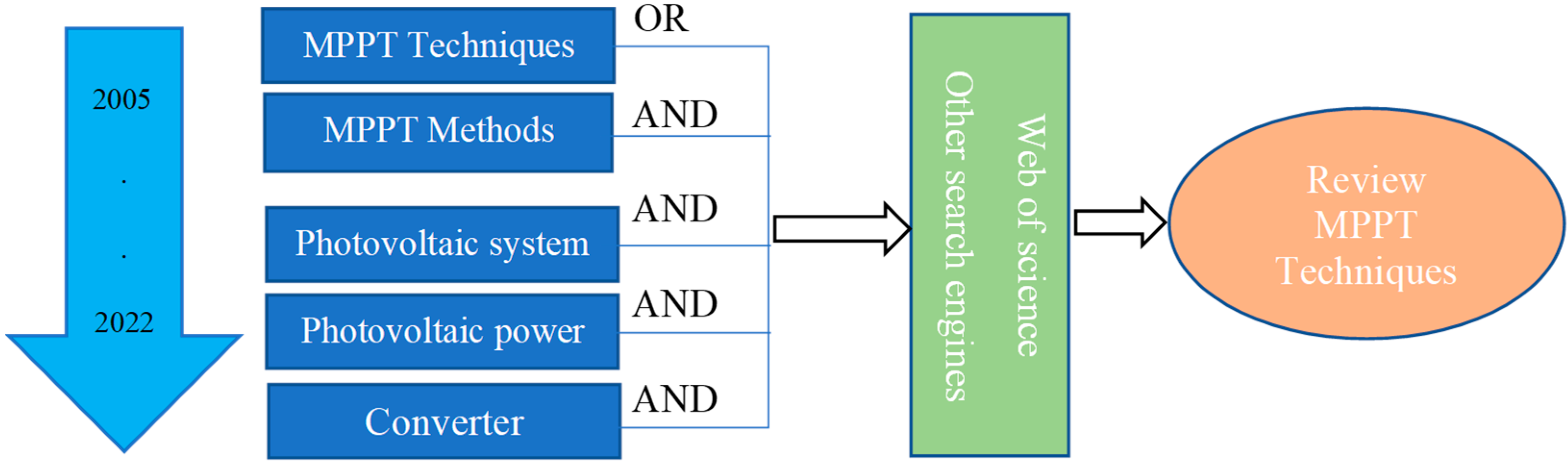
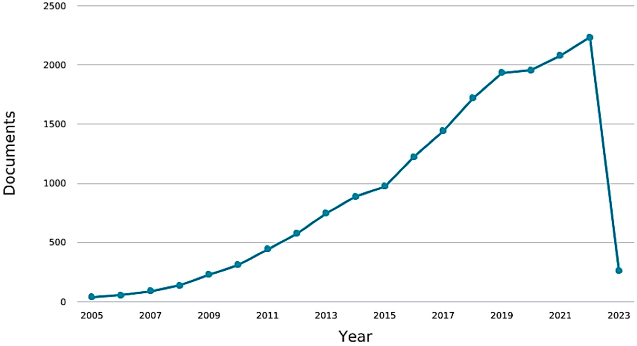
3.2. Step 2: Search
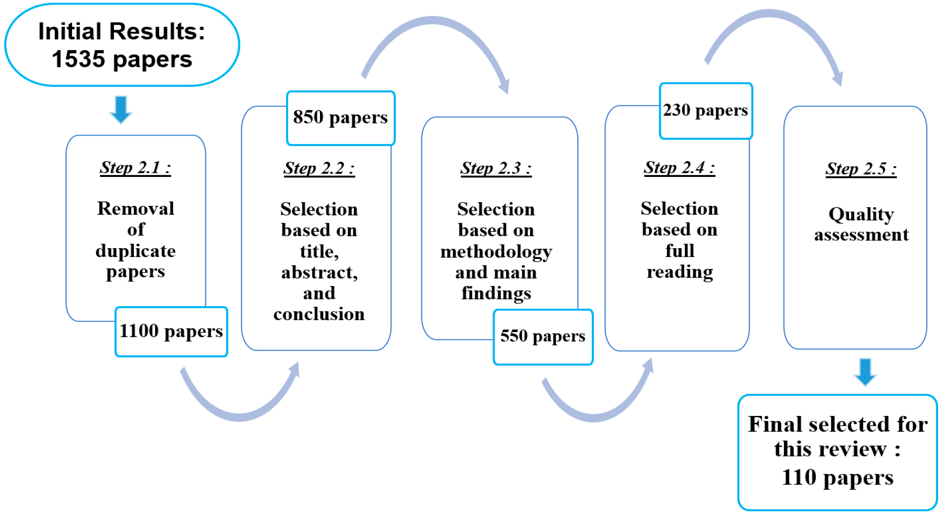
3.3. Step 3: Appraisal
3.4. Step 4: Synthesis
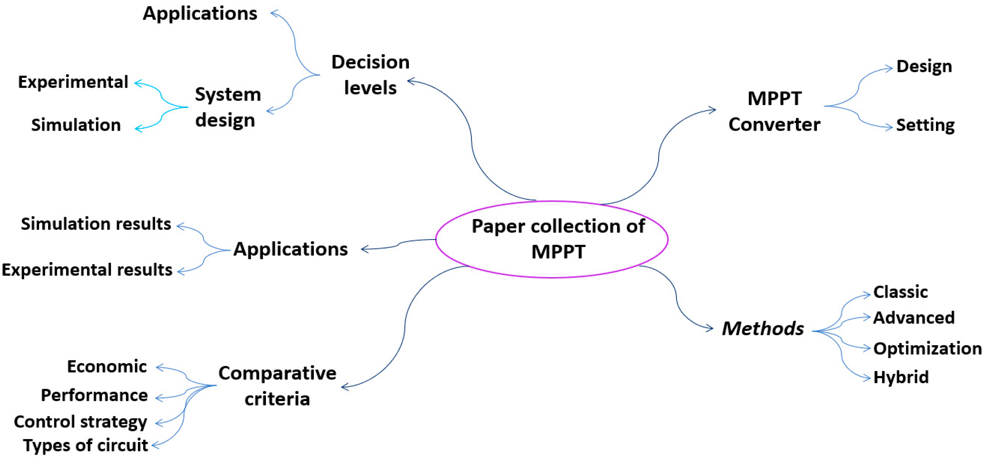
- Decision levels: The papers were divided into four decision levels: theoretical, system design, implementation (experimental or simulation), and comparative criteria.
- Methods: This classification refers to the different kinds of MPPT techniques. The studies were divided into classic, advanced, smart, and hybrid techniques.
- Converter design: This refers to the type of the converter used by the authors to implement the MPPT solutions, namely buck converter, boost converter, etc.
- MPPT applications: This refers to the special cases used by some authors based either on simulation results or experimental results for which the kind of experimental context is defined.
- Comparative criteria: This refers to the criteria used to compare different MPPT techniques and assess their performance.
3.5. Step 5: Analysis
3.5.1. Qualitative Analysis
3.5.2. Quantitative Analysis
A. Comparative Study of Some MPPT Methods
- A.1
- Perturb and Observe
- A.2
- Incremental Conductance
- A.3
- Double Integral Sliding Mode Control
- ■
- Computing the reference trajectories and ;
- ■
- Design of the sliding mode surface;
- ■
- Definition of the switching function.
- A.4
- Particle Swarm Optimization
- A.5
- Fuzzy Logic Controller
- A.6
- Artificial Neural Network
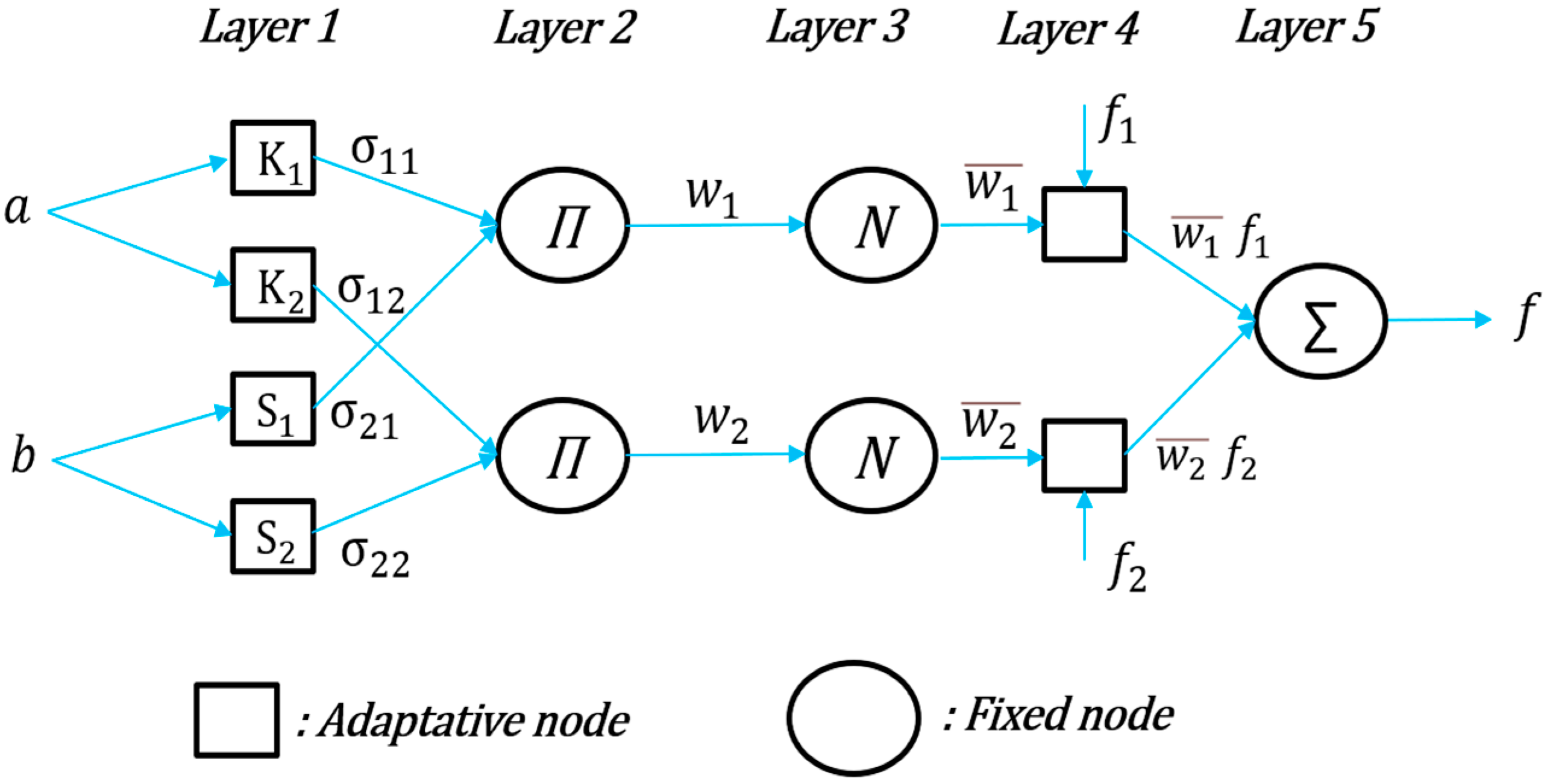
- A.7
- Adaptive Neuro-Fuzzy Inference System (ANFIS)
B. PV System Presentation
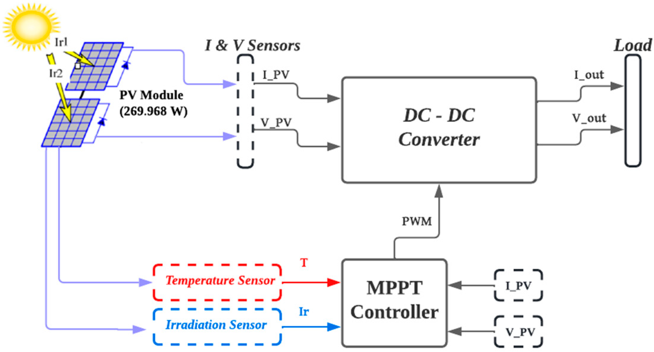
- B.1
- General System Description
- B.2
- Converter Design
C. Results and Discussion
- ■
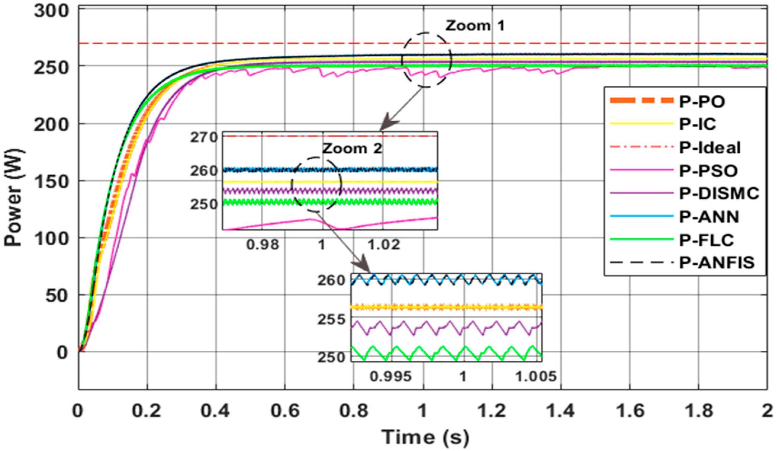
- Test 1: Steady weather
- ■
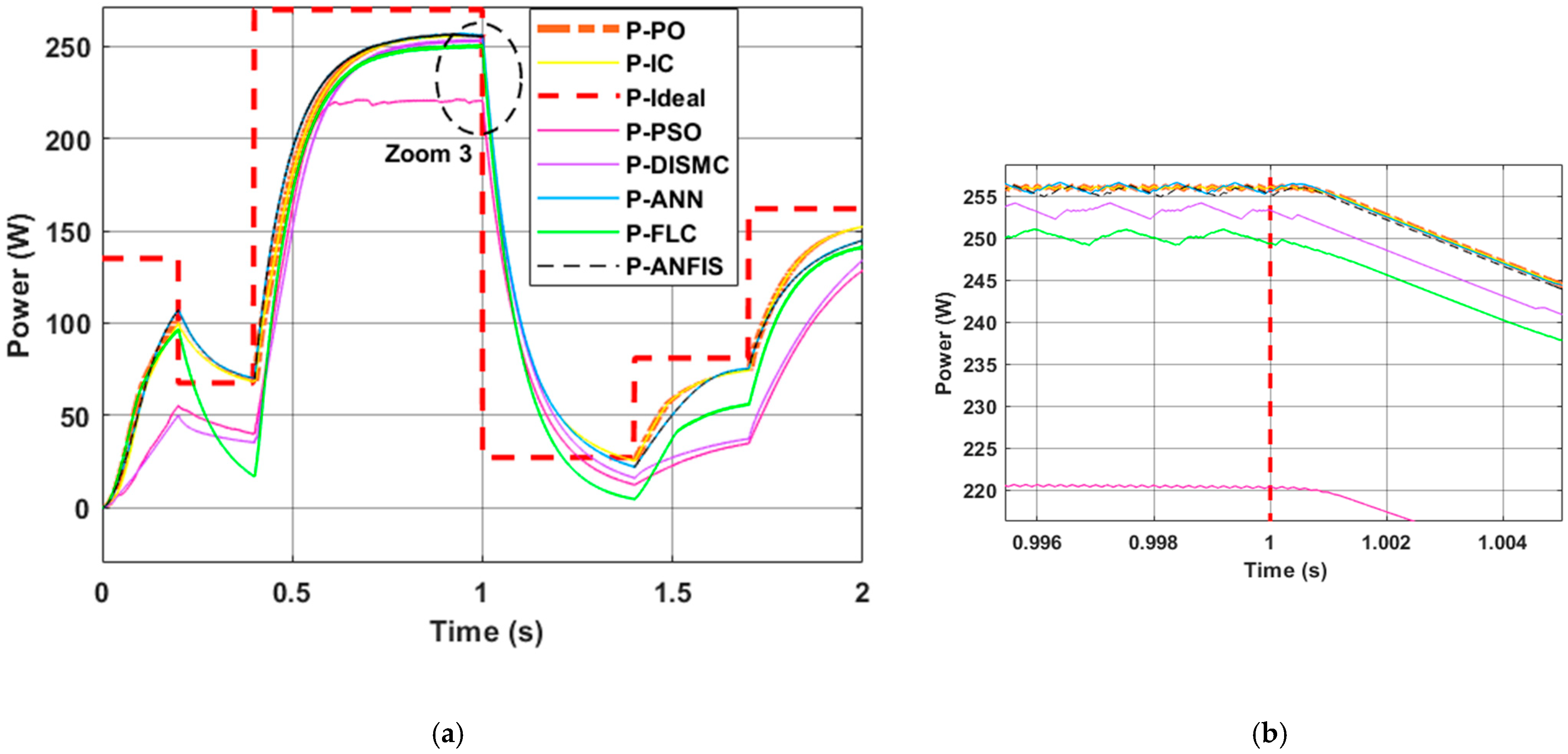
- Test 2: Dynamic weather
- is the output power of the PV panel under MPPT control and can be calculated as the product of the voltage and current at the MPP of the PV panel;
- is the output power of the boost converter and can be calculated as the product of the output voltage and load current;
- is the ideal theorical power of the PV panel.
3.6. Step 6: Benchmarking
4. Conclusions
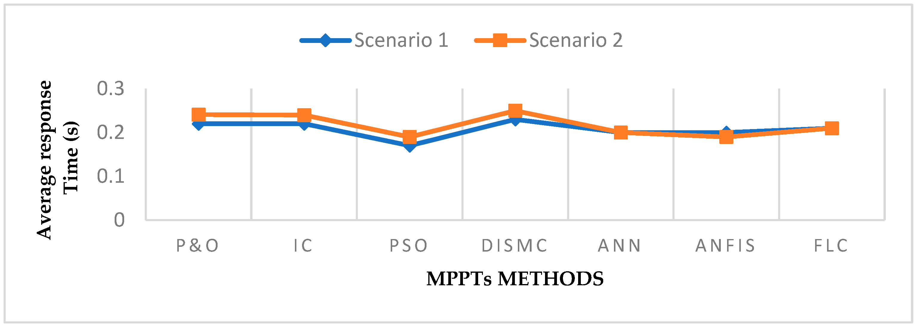
- ✓
- All MPPT controllers are capable of extracting the maximum power from the system at different irradiation values, though their performance levels may vary. For instance, during steady-state weather conditions, the ANN technique demonstrated an efficiency of 98.6%, closely followed by the ANFIS method at 98.34% efficiency.
- ✓
- The P&O technique has a better response time than the IC technique, with minor variations, and the PSO technique requires less processing than other techniques. For example, under steady-state weather conditions, the P&O technique had a response time of 0.322 s, followed closely by the IC method with a response time of 0.326 s.
- ✓
- The simplest approaches, such as PSO and DISMC, are easier to use but have lower efficiency than ANN, ANFIS, and FLC techniques when exposed to irradiation and temperature variations.
- ✓
- The MPP controllers based on neural networks, fuzzy logic, and ANFIS perform significantly better than conventional approaches in terms of tracking efficiency, convergence time, and oscillations around the MPP.
- ✓
- The ANN, FLC, and ANFIS methods relying on machine learning require advanced gears to run these algorithms. The usage of these contemporary strategies in current PV grid deployments can be attributed to the computing hardware’s steadily improving performance-to-price ratio.
Funding
Data Availability Statement
Conflicts of Interest
References
- Kılıç, U.; Kekezoğlu, B. A review of solar photovoltaic incentives and Policy: Selected countries and Turkey. Ain Shams Eng. J. 2022, 13, 101669. [Google Scholar] [CrossRef]
- Pandey, A.; Tyagi, V.; Jeyraj, A.; Selvaraj, L.; Rahim, N.; Tyagi, S. Recent advances in solar photovoltaic systems for emerging trends and advanced applications. Renew. Sustain. Energy Rev. 2016, 53, 859–884. [Google Scholar] [CrossRef]
- IEA. Mid-Term Renewable Energy Market Report; IEA: Paris, France, 2015; Available online: https://www.iea.org/reports/medium-term-renewable-energy-market-report-2015 (accessed on 15 July 2022).
- Aanesen, K.; Heck, S.; Pinner, D. Solar power. Darkest before dawn. McKinsey Sustain. Resour. Product. 2017, 14, 1–16. [Google Scholar]
- Uruel-Sanz, J.; Perpiñán-Lamigueiro, O. Power Flow Analysis in Urban Distribution Networks with Implementation of Grid-Connected Photovoltaic Systems. Solar 2022, 2, 32–51. [Google Scholar] [CrossRef]
- Chen, Y.-K.; Hsu, H.-W.; Song, C.-C.; Chen, Y.-S. High-Flexibility MPPT Techniques with Communication Scan Network for PV Micro-Grid System. Processes 2022, 10, 117. [Google Scholar] [CrossRef]
- Dufo-López, R.; Cortés-Arcos, T.; Artal-Sevil, J.S.; Bernal-Agustín, J.L. Comparison of Lead-Acid and Li-Ion Batteries Lifetime Prediction Models in Stand-Alone Photovoltaic Systems. Appl. Sci. 2021, 11, 1099. [Google Scholar] [CrossRef]
- Khezri, R.; Mahmoudi, A.; Haque, M.H. A Demand Side Management Approach For Optimal Sizing of Standalone Renewable-Battery Systems. IEEE Trans. Sustain. Energy 2021, 12, 2184–2194. [Google Scholar] [CrossRef]
- Saleh, U.A.; Johar, M.A.; Jumaat, S.A.B.; Rejab, M.N.; Jamaludin, W.A.W. Evaluation of a PV-TEG Hybrid System Configuration for an Improved Energy Output: A Review. Int. J. Renew. Energy Dev. 2021, 10, 385. [Google Scholar] [CrossRef]
- Fernández, L. Cumulative Installed Solar PV Capacity Worldwide from 2000 to 2021. Available online: https://www.statista.com/statistics/280220/global-cumulative-installed-solar-pv-capacity/ (accessed on 23 July 2022).
- Mishu, M.K.; Rokonuzzaman, M.; Pasupuleti, J.; Shakeri, M.; Rahman, K.S.; Hamid, F.A.; Tiong, S.K.; Amin, N. Prospective efficient ambient energy harvesting sources for IoT-equipped sensor applications. Electronics 2020, 9, 1345. [Google Scholar] [CrossRef]
- El-Khozondar, H.J.; El-Khozondar, R.J.; Matter, K.; Suntio, T. A review study of photovoltaic array maximum power tracking algorithms. Renewables 2016, 3, 1–8. [Google Scholar] [CrossRef]
- Karami, N.; Moubayed, N.; Outbib, R. General review and classification of different MPPT Techniques. Renew. Sustain. Energy Rev. 2017, 68, 1–18. [Google Scholar] [CrossRef]
- Danandeh, M.A.; Mousavi, G.S.M. Comparative and Comprehensive Review of Maximum Power Point Tracking Methods for PV Cells. Renew. Sustain. Energy Rev. 2018, 82, 2743–2767. [Google Scholar] [CrossRef]
- Ahmad, R.; Murtaza, A.F.; Sher, H.A. Power tracking techniques for efficient operation of photovoltaic array in solar applications—A review. Renew. Sustain. Energy Rev. 2019, 101, 82–102. [Google Scholar] [CrossRef]
- Bollipo, R.B.; Mikkili, S.; Bonthagorla, P.K. Hybrid, Optimization, Intelligent and Classical PV MPPT techniques: Review. CSEE J. Power Energy Systems. 2021, 7, 9–33. [Google Scholar] [CrossRef]
- Lawan, M.; Aboushady, A.; Ahmed, K.H. Photovoltaic MPPT Techniques Comparative Review. In Proceedings of the 9th International Conference on Renewable Energy Research and Applications, Glasgow, UK, 27–30 September 2020; pp. 344–351. [Google Scholar] [CrossRef]
- Awan, M.M.A. A Technical Review of MPPT Algorithms for Solar Photovoltaic System: SWOT Analysis of MPPT Algorithm. Sir Syed Univ. Res. J. Eng. Technol. 2022, 12, 98–106. [Google Scholar] [CrossRef]
- Mengist, W.; Soromessa, T.; Legese, G. Method for conducting systematic literature review and meta-analysis for environmental science research. MethodsX 2022, 7, 100777. [Google Scholar] [CrossRef]
- Iliescu, A.N. Conceptual atlas of the knowmad literature: Visual mapping with VOSviewer. Manag. Dyn. Knowl. Econ. 2021, 9, 379–392. [Google Scholar]
- Verma, D.; Nema, S.; Shandilya, A.M.; Dash, S.K. Maximum Power Point Tracking (MPPT) Techniques: Recapitulation in Solar Photovoltaic Systems. Renew. Sustain. Energy Rev. 2016, 54, 1018–1034. [Google Scholar] [CrossRef]
- Subudhi, B.; Pradhan, R. A Comparative Study on Maximum Power Point Tracking Techniques for Photovoltaic Power Systems. IEEE Trans. Sustain. Energy 2013, 4, 89–98. [Google Scholar] [CrossRef]
- Sanju; Agarwal, K.L.; Srikant, S.S. An Analysis of State of Art Maximum Power Point Tracking Techniques of the Solar Photovoltaic System under Partial Shading Conditions. In Proceedings of the 2022 IEEE 10th Power India International Conference (PIICON), New Delhi, India, 25–27 November 2022; pp. 1–6. [Google Scholar] [CrossRef]
- De Brito, M.A.G.; Galotto, L.; Sampaio, L.P.; e Melo, G.D.A.; Canesin, C.A. Evaluation of the Main MPPT Techniques for Photovoltaic Applications. IEEE Trans. Ind. Electron. 2013, 60, 1156–1167. [Google Scholar] [CrossRef]
- Ahmed, J.; Salam, Z. An Enhanced Adaptive P&O MPPT for Fast and Efficient Tracking Under Varying Environmental Conditions. IEEE Trans. Sustain. Energy 2018, 9, 1487–1496. [Google Scholar] [CrossRef]
- Ahmed, J.; Salam, Z. An improved perturb and observe (P&O) maximum power point tracking (MPPT) algorithm for higher efficiency. Appl. Energy 2015, 150, 97–108. [Google Scholar]
- Mishu, M.K.; Rokonuzzaman, R.; Pasupuleti, J.; Shakeri, M.; Rahman, K.S.; Binzaid, S.; Tiong, S.K.; Amin, N. An adaptive TE-PV hybrid energy harvesting system for self-powered IoT sensor applications. Sensors 2021, 21, 2604. [Google Scholar] [CrossRef]
- Singh, S.; Manna, S.; Mansoori, M.I.H.; Akella, A.K. Implementation of Perturb & Observe MPPT Technique using Boost converter in PV System. In Proceedings of the IEEE International Conference on Computational Intelligence for Smart Power System and Sustainable Energy (CISPSSE-2020), Odisha, India, 29–31 July 2020. [Google Scholar]
- Esram, T.; Chapman, P.L. Comparison of photovoltaic array maximum power point tracking techniques. IEEE Trans. Energy Convers. 2007, 22, 439–449. [Google Scholar] [CrossRef]
- Cabal, C.; Martnez-Salamero, L.; Sguier, L.; Alonso, C.; Guinjoan, F. Maximum power point tracking based on slidingmode control for output-series connected converters in photovoltaic systems. IET Power Electron. 2014, 7, 914–923. [Google Scholar] [CrossRef]
- Bianconi, E.; Calvente, J.; Giral, R.; Mamarelis, E.; Petrone, G.; Ramos-Paja, C.A.; Spagnuolo, G.; Vitelli, M. A Fast Current-Based MPPT Technique Employing Sliding Mode Control. IEEE Trans. Ind. Electron. 2013, 60, 1168–1178. [Google Scholar] [CrossRef]
- Islam, H.; Mekhilef, S.; Shah, N.B.M.; Soon, T.K.; Seyedmahmousian, M.; Horan, B.; Stojcevski, A. Performance evaluation of maximum power point tracking approaches and photovoltaic systems. Energies 2018, 11, 365. [Google Scholar] [CrossRef]
- OLiviera da Silva, S.A.; Sampaio, L.P.; de Oliveira, F.M.; Durand, F.R. Feed-forward DC-bus control loop applied to a single-phase grid-connected PV system operating with PSO-based MPPT technique and active power-line conditioning. IET Renew. Power Gener. 2017, 11, 183–193. [Google Scholar] [CrossRef]
- Alturki, F.A.; Al-Shamma’a, A.A.; Farh, H.M.H. Simulations and dSPACE Real-Time Implementation of Photovoltaic Global Maximum Power Extraction under Partial Shading. Sustainability 2020, 12, 3652. [Google Scholar] [CrossRef]
- Sampaio, L.P.; da Rocha, M.V.; OLiviera da Silva, S.A.; de Freitas, M.H.T. Comparative analysis of MPPT algorithms bio-inspired by grey wolves employing a feed-forward control loop in a three-phase grid-connected photovoltaic system. IET Renew. Power Gener. 2019, 13, 1379–1390. [Google Scholar] [CrossRef]
- Bhatti, A.R.; Salam, Z.; Sultana, B.; Rasheed, N.; Awan, A.B.; Sultana, U.; Younas, M. Optimized sizing of photovoltaic grid-connected electric vehicle charging system using particle swarm optimization. Int. J. Energy Res. 2019, 43, 500–522. [Google Scholar] [CrossRef]
- Seyedmahmoudian, M.; Horan, B.; Soon, T.K.; Rahmani, R.; Oo, A.M.T.; Mekhilef, S.; Stojcevski, A. State of the art artificial intelligencebased MPPT techniques for mitigating partial shading effects on PV systemsA review. Renew. Sustain. Energy Rev. 2016, 64, 435–455. [Google Scholar] [CrossRef]
- Zhu, T.; Dong, J.; Li, X.; Ding, S. A Comprehensive Study on Maximum Power Point Tracking Techniques Based on Fuzzy Logic Control for Solar Photovoltaic Systems. Front. Energy Res. 2021, 9, 727949. [Google Scholar] [CrossRef]
- Ali, R.B.; Bouadila, S.; Mami, A. Development of a Fuzzy Logic Controller applied to an agricultural greenhouse experimentally validated. Appl. Therm. Eng. 2018, 141, 798–810. [Google Scholar] [CrossRef]
- Kuate Nkounhawa, P.; Ndapeu, D.; Kenmeugne, B. Artifcial neural network (ANN) and adaptive neuro fuzzy inference system (ANFIS): Application for a photovoltaic system under unstable environmental conditions. Int. J. Energy Environ. Eng. 2022, 13, 821–829. [Google Scholar] [CrossRef]
- Kuate Nkounhawa, P.; Ndapeu, D.; Kenmeugne, B. MPPT Based on Artificial Neural Networks (ANN) for a Photovoltaic System under Unstable Environmental Conditions. Res. Sq. 2021, Preprint. [Google Scholar] [CrossRef]
- Dixit, T.V.; Yadav, A.; Gupta, S. Experimental assessment of maximum power extraction from solar panel with different converter topologies. Int. Trans. Electr. Energy Syst. 2019, 29, e2712. [Google Scholar] [CrossRef]
- Miyatake, M.; Inada, T.; Hiratsuka, I.; Zhao, H.; Otsuka, H.; Nakano, M. Control characteristics of a fibonacci-search-based maximum power point tracker when a photovoltaic array is partially shaded. In Proceedings of the 4th International Power Electronics and Motion Control Conference, 2004—IPEMC 2004, Xi’an, China, 14–16 August 2004; pp. 816–821. [Google Scholar]
- Carvalho, J.L.; Kretly, L.C. Modified Newton-Raphson Method to Achieve Variable Step Hill-Climbing Algorithm for Maximum Power Point Tracking. In Proceedings of the 2021 IEEE International Conference on Microwaves, Antennas, Communications and Electronic Systems (COMCAS), Tel Aviv, Israel, 1–3 November 2021; pp. 442–447. [Google Scholar] [CrossRef]
- Jiang, J.-A.; Su, Y.-L.; Kuo, K.-C.; Wang, C.-H.; Liao, M.-S.; Wang, J.-C.; Huang, C.-K.; Chou, C.-Y.; Lee, C.-H.; Shieh, J.-C. On a hybrid MPPT control scheme to improve energy harvesting performance of traditional two-stage inverters used in photovoltaic systems. Renew. Sustain. Energy Rev. 2017, 69, 1113–1128. [Google Scholar] [CrossRef]
- Mohapatra, A.; Nayak, B.; Das, P.; Mohanty, K.B. A review on MPPT techniques of PV system under partial shading condition. Renew. Sustain. Energy Rev. 2017, 80, 854–867. [Google Scholar] [CrossRef]
- Vimalarani, C.; Kamaraj, N. Improved method of maximum power point tracking of photovoltaic (PV) array using hybrid intelligent controller. Optik 2018, 168, 403–415. [Google Scholar]
- Nikolovski, S.; Reza Baghaee, H.; Mlakić, D. ANFIS-based peak power shaving/curtailment in microgrids including PV units and BESSs. Energies 2018, 11, 2953. [Google Scholar] [CrossRef]
- Mohammed, K.K.; Buyamin, S.; Shams, I.; Mekhilef, S. Maximum power point tracking based on adaptive neuro-fuzzy inference systems for a photovoltaic system with fast varying load conditions. Int. Trans. Electr. Energy Syst. 2021, 31, e12904. [Google Scholar] [CrossRef]
- Aldair, A.A.; Obed, A.A.; Halihal, A.F. Design and implementation of ANFIS-reference model controller based MPPT using FPGA for photovoltaic system. Renew. Sustain. Energy Rev. 2018, 82, 2202–2217. [Google Scholar] [CrossRef]
- Abadi, I.; Imron, C.; Noriyati, R.D. Implementation of maximum power point tracking (MPPT) technique on solar tracking system based on adaptive neuro-fuzzy inference system (ANFIS). E3s Web Conf. 2018, 43, 01014. [Google Scholar] [CrossRef]
- Kchaou, A.; Naamane, A.; Koubaa, Y.; M’Sirdi, N.K. Comparative study of different mppt techniques for a stand-alone pv system. In Proceedings of the 2016 17th International Conference on Sciences and Techniques of Automatic Control and Computer Engineering (STA), Sousse, Tunisia, 19–21 December 2016; pp. 629–634. [Google Scholar]
- Boukenoui, R.; Bradai, R.; Mellit, A.; Ghanes, M.; Salhi, H. Comparative analysis of p&o, modified hill climbing-flc, and adaptive p&o-flc mppts for microgrid standalone pv system. In Proceedings of the 2015 International Conference on Renewable Energy Research and Applications (ICRERA), Palermo, Italy, 22–25 November 2015; pp. 1095–1099. [Google Scholar]
- Nademi, H.; Elahidoost, A.; Norum, L.E. Comparative analysis of different mppt schemes for photovoltaic integration of modular multilevel converter. In Proceedings of the 2016 IEEE 17th Workshop on Control and Modeling for Power Electronics (COMPEL), Trondheim, Norway, 27–30 June 2016; pp. 1–5. [Google Scholar]
- Ali, A.I.; Sayed, M.A.; Mohamed, E.E. Modified efficient perturb and observe maximum power point tracking technique for grid-tied pv system. Int. J. Electr. Power Energy Syst. 2018, 99, 192–202. [Google Scholar] [CrossRef]
- Ahmed, J.; Salam, Z. A modified p o maximum power point tracking method with reduced steady-state oscillation and improved tracking efficiency. IEEE Trans. Sustain. Energy 2016, 7, 1506–1515. [Google Scholar] [CrossRef]
- Yin, L.; Yu, S.; Zhang, X.; Tang, Y. Simple adaptive incremental conductance mppt algorithm using improved control model. J. Renew. Sustain. Energy 2017, 9, 065501. [Google Scholar] [CrossRef]
- Yetayew, T.T.; Jyothsna, T.R.; Kusuma, G. Evaluation of incremental conductance and firefly algorithm for pv mppt application under partial shade condition. In Proceedings of the 2016 IEEE 6th International Conference on Power Systems (ICPS), New Delhi, India, 4–6 March 2016; pp. 1–6. [Google Scholar]
- Gupta, A.K.; Pachauri, R.K.; Maity, T.; Chauhan, Y.K.; Mahela, O.P.; Khan, B.; Gupta, P.K. Effect of Various Incremental Conductance MPPT Methods on the Charging of Battery Load Feed by Solar Panel. IEEE Access 2021, 9, 90977–90988. [Google Scholar] [CrossRef]
- Rougab, I.; Cheknane, A.; Abouchabana, N. Study and simulation of MPPT techniques to control a stand-alone photovoltaic system under varying irradiance. Rom. J. Inf. Technol. Autom. Control 2021, 31, 109–122. [Google Scholar] [CrossRef]
- Trivedi, A.; Gupta, A.; Pachauri, R.K.; Chauhan, Y.K. Comparison of perturb observe and ripple correlation control mppt algorithms for pv array. In Proceedings of the 2016 IEEE 1st International Conference on Power Electronics, Intelligent Control and Energy Systems (ICPEICES), Delhi, India, 4–6 July 2016; pp. 1–5. [Google Scholar]
- Tolentino, L.K.S.; Cruz, F.R.G.; Garcia, R.G.; Chung, W.Y. Maximum power point tracking controller ic based on ripple correlation control algorithm. In Proceedings of the 2015 International Conference on Humanoid, Nanotechnology, Information Technology, Communication and Control, Environment and Management (HNICEM), Cebu, Philippines, 9–12 December 2015; pp. 1–6. [Google Scholar]
- Esram, T.; Kimball, J.W.; Krein, P.T.; Chapman, P.L.; Midya, P. Dynamic maximum power point tracking of photovoltaic array using ripple correlation control. IEEE Trans. Power Electron. 2006, 21, 1282–1291. [Google Scholar] [CrossRef]
- Kjær, S.B. Evaluation of the “hill climbing” and the “incremental conductance” maximum power point trackers for photovoltaic power systems. IEEE Trans. Energy Convers. 2012, 27, 922–929. [Google Scholar] [CrossRef]
- Jately, V.; Arora, S. Performance Investigation of Hill-Climbing MPPT Techniques for PV Systems Under Rapidly Changing Environment. In Intelligent Communication, Control and Devices; Singh, R., Choudhury, S., Gehlot, A., Eds.; Advances in Intelligent Systems and Computing; Springer: Singapore, 2018; Volume 624. [Google Scholar] [CrossRef]
- Kota, V.R.; Bhukya, M.N. A novel linear tangents-based P&O scheme for MPPT of a PV system. Renew. Sustain. Energy Rev. 2017, 71, 257–267. [Google Scholar]
- Sher, H.A.; Murtaza, A.F.; Noman, A.; Addoweesh, K.E.; Al-Haddad, K.; Chiaberge, M. A New Sensorless Hybrid MPPT Algorithm Based on Fractional Short-Circuit Current Measurement and P& O MPPT. IEEE Trans. Sustain. Energy 2015, 6, 1426–1434. [Google Scholar] [CrossRef]
- Zheng, Y.; Wang, W.; Chen, W.; Li, Q. Research on mppt of photovoltaic system based on pso under partial shading condition. In Proceedings of the 2016 35th Chinese Control Conference (CCC), Chengdu, China, 27–29 July 2016; pp. 8654–8659. [Google Scholar]
- Yunliang, W.; Nan, B. Research of mppt control method based on pso algorithm. In Proceedings of the 2015 4th International Conference on Computer Science and Network Technology (ICCSNT), Harbin, China, 14-16 August 2004; Volume 1, pp. 698–701. [Google Scholar]
- Renaudineau, H.; Donatantonio, F.; Fontchastagner, J.; Petrone, G.; Spagnuolo, G.; Martin, J.P.; Pierfederici, S. A pso-based global mppt technique for distributed pv power generation. IEEE Trans. Ind. Electron. 2015, 62, 1047–1058. [Google Scholar] [CrossRef]
- Kermadi, M.; Berkouk, E.M. A maximum power point tracker based on particle swarm optimization for pv-battery energy system under partial shading conditions. In Proceeding of the 2015 3rd International Conference on Control, Engineering Information Technology (CEIT), Tlemcen, Algeria, 25–27 May 2015; pp. 1–6. [Google Scholar]
- Sharma, A.; Sharma, A.; Jately, V.; Averbukh, M.; Rajput, S.; Azzopardi, B. A Novel TSA-PSO Based Hybrid Algorithm for GMPP Tracking under Partial Shading Conditions. Energies 2022, 15, 3164. [Google Scholar] [CrossRef]
- Zhang, M.; Chen, Z.; Wei, L. An immune firefly algorithm for tracking the maximum power point of pv array under partial shading conditions. Energies 2019, 12, 3083. [Google Scholar] [CrossRef]
- Kofinas, P.; Dounis, A.I.; Papadakis, G.; Assimakopoulos, M.N. An Intelligent MPPT controller based on direct neural control for partially shaded PV system. Energy Build. 2015, 90, 51–64. [Google Scholar] [CrossRef]
- Ahmed, J.; Salam, Z. A soft computing MPPT for PV system based on Cuckoo Search algorithm. In Proceedings of the 4th International Conference on Power Engineering, Energy and Electrical Drives, Istanbul, Turkey, 13–17 May 2013; pp. 558–562. [Google Scholar] [CrossRef]
- Soufyane Benyoucef, A.; Chouder, A.; Kara, K.; Silvestre, S. Artificial bee colony-based algorithm for maximum power point tracking (MPPT) for PV systems operating under partial shaded conditions. Appl. Soft Comput. 2015, 32, 38–48. [Google Scholar] [CrossRef]
- Yu, M.Q. Parameter Identification of Photovoltaic Cell Model Based on Perturbation and Observation and Modified Gauss-Newton Method. In Proceedings of the 2018 37th Chinese Control Conference (CCC), Wuhan, China, 25–27 July 2018; pp. 6127–6131. [Google Scholar] [CrossRef]
- Inomoto, R.S.; Monteiro, J.R.B.D.A.; Filho, A.J.S. Boost Converter Control of PV System Using Sliding Mode Control With Integrative Sliding Surface. IEEE J. Emerg. Sel. Top. Power Electron. 2022, 10, 5522–5530. [Google Scholar] [CrossRef]
- Bianconi, E.; Calvente, J.; Giral, R.; Mamarelis, E.; Petrone, G.; Ramos-Paja, C.A.; Spagnuolo, G.; Vitelli, M. Perturb and observe mppt algorithm with a current controller based on the sliding mode. Int. J. Electr. Power Energy Syst. 2013, 44, 346–356. [Google Scholar] [CrossRef]
- Prasad, L.B.; Sahu, S.; Gupta, M.; Srivastava, R.; Mozhui, L.; Asthana, D.N. An improved method for mppt using ann and ga with maximum power comparison through perturb observe technique. In Proceedings of the 2016 IEEE Uttar Pradesh Section International Conference on Electrical, Computer and Electronics Engineering (UPCON), Varanasi, India, 9–11 December 2016; pp. 206–211. [Google Scholar]
- Liu, Y.H.; Liu, C.L.; Huang, J.W.; Chen, J.H. Neuralnetwork-based maximum power point tracking methods for photovoltaic systems operating under fast changing environments. Sol. Energy 2013, 89, 42–53. [Google Scholar] [CrossRef]
- Kulaksız, A.A.; Akkaya, R. A genetic algorithm optimized ann-based mppt algorithm for a stand-alone pv system with induction motor drive. Sol. Energy 2012, 86, 2366–2375. [Google Scholar] [CrossRef]
- Zhang, J.H.; Wei, X.Y.; Hu, L.; Ma, J.G. A MPPT Method based on Improved Fibonacci Search Photovoltaic Array. Tech. Gaz. 2019, 26, 163–170. [Google Scholar] [CrossRef]
- Li, X.; Wen, H.; Hu, Y.; Jiang, L. A novel beta parameter based fuzzy-logic controller for photovoltaic MPPT application. Renew. Energy 2019, 130, 416–427. [Google Scholar] [CrossRef]
- Pradhan, R.; Subudhi, B. Double integral sliding mode MPPT control of a photovoltaic system. IEEE Trans. Contr. Syst. Technol. 2016, 24, 285–292. [Google Scholar] [CrossRef]
- Kandemir, E.; Cetin, N.S.; Borekci, S. A comprehensive overview of maximum power extraction methods for PV systems. Renew. Sustain. Energy Rev. 2017, 78, 93–112. [Google Scholar] [CrossRef]
- Mahdi, A.S.; Mahamad, A.K.; Saon, S.; Tuwoso, T.; Elmunsyah, H.; Mudjanarko, S.W. Maximum power point tracking using perturb and observe, fuzzy logic and ANFIS. SN Appl. Sci. 2022, 2, 89. [Google Scholar] [CrossRef]
- Priyadarshi, N.; Azam, F.; Sharma, A.K.; Vardia, M. An Adaptive Neuro Fuzzy Inference System-Based Intelligent Grid-Connected Photovoltaic Power Generation. In Advances in Computational Intelligence; Sahana, S.K., Bhattacharjee, V., Eds.; Springer: Singapore, 2020; Chapter 1; Volume 988, pp. 3–14. [Google Scholar] [CrossRef]
- Mohanty, S.; Subudhi, B.; Ray, P.K. A Grey Wolf-Assisted Perturb & Observe MPPT Algorithm for a PV System. IEEE Trans. Energy Convers. 2017, 32, 340–347. [Google Scholar] [CrossRef]
- Sundareswaran, K.; Palani, S. Application of a combined particle swarm optimization and perturb and observe method for MPPT in PV systems under partial shading conditions. Renew. Energy 2015, 75, 308–317. [Google Scholar] [CrossRef]
- Lasheen, M.; Abdel-Salam, M. Maximum power point tracking using Hill Climbing and ANFIS techniques for PV applications: A review and a novel hybrid approach. Energy Convers. Manag. 2018, 171, 1002–1019. [Google Scholar] [CrossRef]
- Shebani, M.M.; Iqbal, T.; Quaicoe, J.E. Comparing bisection numerical algorithm with fractional short circuit current and open circuit voltage methods for MPPT photovoltaic systems. In Proceedings of the 2016 IEEE Electrical Power and Energy Conference (EPEC), Ottawa, ON, Canada, 12–14 October 2016; pp. 1–5. [Google Scholar] [CrossRef]
- Sias, Q.A.; Robandi, I. Recurrence Perturb and Observe Algorithm for MPPT Optimization under Shaded Condition. In Proceedings of the 2016 International Seminar on Intelligent Technology and Its Applications (ISITIA), Lombok, Indonesia, 28–30 July 2016. [Google Scholar] [CrossRef]
- Faraji, R.; Rouholamini, A.; Naji, H.R.; Fadaeinedjad, R.; Chavoshian, M.R. FPGA-based real time incremental conductance maximum power point tracking controller for photovoltaic systems. IET Power Electron. 2014, 7, 12941304. [Google Scholar] [CrossRef]
- Yang, L.; Yunbo, Z. A Novel Improved Variable Step Size INC MPPT Method for a PV Systems. In Proceedings of the 2019 Chinese Control And Decision Conference (CCDC), Nanchang, China, 3–5 June 2019. [Google Scholar]
- Ishaque, K.; Salam, Z. A deterministic particle swarm optimization maximum power point tracker for photovoltaic system under partial shad ing condition. IEEE Trans. Ind. Electron. 2013, 60, 3195–3206. [Google Scholar]
- Lian, K.L.; Jhang, J.H.; Tian, I.S. A maximum power point tracking method based on perturb-and-observe combined with particle swarm optimization. IEEE J. Photovolt. 2014, 4, 626–633. [Google Scholar] [CrossRef]
- Khairi, M.N.S.; Bakhari, N.A.B.; Samat, A.A.A.; Kamarudin, N.; Hussin, M.H.M.; Tajudin, A.I. MPPT Design Using PSO Technique for Photovoltaic System. In Proceedings of the 2023 IEEE 3rd International Conference in Power Engineering Applications (ICPEA), Putrajaya, Malaysia, 6–7 March 2023; pp. 131–136. [Google Scholar] [CrossRef]
- Calvinho, G.; Pombo, J.; Mariano, S.; Calado, M.D.R. Design and implementation of MPPT system based on PSO algorithm. In Proceedings of the 2018 International Conference on Intelligent Systems, Funchal, Portugal, 25–27 September 2018; pp. 733–738. [Google Scholar] [CrossRef]
- Nasser, K.W.; Yaqoob, S.J.; Hassoun, Z.A. Improved dynamic performance of photovoltaic panel using fuzzy logic-MPPT algorithm. Indones. J. Electr. Eng. Comput. Sci. 2021, 21, 617–624. [Google Scholar] [CrossRef]
- Rai, A.K.; Kaushika, N.D.; Singh, B.; Agarwal, N. Simulation model of ANN based maximum power point tracking controller for solar PV system. Sol. Energy Mater. Sol. Cells 2011, 95, 773–778. [Google Scholar] [CrossRef]
- Kulaksiz, A.; Akkaya, R. Training data optimization for ANNs using genetic algorithms to enhance MPPT efficiency of a stand-alone PV system. Turk. J. Electr. Eng. Comput. Sci. 2012, 20, 241–254. [Google Scholar] [CrossRef]
- Jang Ankaiah, B.; Nageswararao, J. MPPT algorithm for solar photovotaic cell by incremental conductance method. Int. J. Innov. Eng. Technol. 2013, 2, 17–23. [Google Scholar]
- Kiranmai, K.P.; Veerachary, M. Maximum power point tracking: A PSPICE circuit simulator approach. In Proceedings of the 2005 International Conference on Power Electronics and Drives Systems, Kuala Lumpur, Malaysia, 8 November–1 December 2005; pp. 1072–1077. [Google Scholar]
- Kwan, T.H.; Wu, X. High performance P&O based lock-on mechanism MPPT algorithm with smooth tracking. Sol. Energy 2017, 155, 816–828. [Google Scholar]
- Balasankar, R.; Arasu, G.T.; Raj, J.C.M. A global MPPT technique invoking partitioned estimation and strategic deployment of P&O to tackle partial shading conditions. Sol. Energy 2017, 143, 73–85. [Google Scholar]
- Kchaou, A.; Naamane, A.; Koubaa, Y.; M’sirdi, N. Second order sliding mode-based MPPT control for photovoltaic applications. Sol. Energy 2017, 155, 758–769. [Google Scholar] [CrossRef]
- Zongo, O.A. Comparing the Performances of MPPT Techniques for DC-DC Boost Converter in a PV System. Walailak J. Sci. Technol. 2021, 18, 6500. [Google Scholar] [CrossRef]
- Gopi, R.R.; Sreejith, S. Converter topologies in photovoltaic applications—A review. Renew. Sustain. Energy Rev. 2018, 94, 1–14. [Google Scholar] [CrossRef]
- Ramos-Hernanz, J.; Lopez-Guede, J.M.; Barambones, O.; Zulueta, E.; Fernandez-Gamiz, U. Novel control algorithm for MPPT with Boost converters in photovoltaic systems. Int. J. Hydrogen Energy 2017, 42, 17831–17855. [Google Scholar] [CrossRef]
- Ayop, R.; Tan, C.W. Design of boost converter based on maximum power point resistance for photovoltaic applications. Sol. Energy 2018, 160, 322–335. [Google Scholar] [CrossRef]
- Olivier, W. Comparative Study of MPPT Algorithms for Space Applications. 2022. Digital Access to Libraries. Available online: https://hdl.handle.net/2078.1/thesis:35560 (accessed on 4 February 2023).


| Refs. | Year | Selected Keywords | One-Sentence Summary | Topic of Paper | Benchmarking | ||
|---|---|---|---|---|---|---|---|
| Review | Systematic Review | Quantitative Analysis | Qualitative Analysis | ||||
| [12] | 2016 | MPPT, PV, System efficiency | Review study of 62 MPPT algorithms | ˟ | ˟ | ||
| [13] | 2016 | MPP, MPPT, PV, converter, power electronics | Overview of 40 old and recent MPPT methods | ˟ | ˟ | ||
| [14] | 2018 | MPPT, PV, PV cell | Comparative and comprehensive review of MPPT methods for PV cells | ˟ | ˟ | ˟ | |
| [15] | 2019 | PV system, MPPT techniques, conventional methods, partial shading, bio-inspired algorithms | Thorough summary of the many MPPT methods that have recently been developed, modeled, and/or experimentally verified in PV literature | ˟ | ˟ | ||
| [16] | 2020 | GMPP, MPPT classification, MPPT techniques, partial PSCs, PV system | A detailed examination of the hybrid, optimized, intelligent, and classical MPPT techniques | ˟ | ˟ | ||
| [17] | 2020 | MPPT, PV, grid-connected | Critical review of some of the most recent MPPT techniques developed | ˟ | ˟ | ||
| [18] | 2022 | GMPPT, PSC, PV system, uniform weather condition, MPPT algorithms. | Present the strengths, weaknesses, opportunities, and threats (SWOT analysis) of MPPT algorithms. | ˟ | ˟ | ||
| The current paper | 2023 | MPPT techniques, photovoltaic system, converter, systematic literature review, state of the art, meta-analysis, comparative study, simulation results, benchmarking. | High-level systematic literature review of MPPT methods | ˟ | ˟ | ˟ | ˟ |
| N° | Steps | Results | Methods |
|---|---|---|---|
| 1 | Protocol | Definition of the scope of the study | Formulate research questions |
| 2 | Search | Definition of the research strategy Searching studies | Search for strings Search for databases |
| 3 | Appraisal | Selection of studies Assessment of research quality | Define the criteria for inclusion and exclusion Quality criteria |
| 4 | Synthesis | Data extraction Data classification by categories | Extract template Organize data according to some iterative definition to prepare it for additional analysis. |
| 5 | Analysis | Analysis of the data Results and discussion | Description, quantitative categories, narrative analysis, and qualitative analysis of the organized data Show the trends, highlight the gaps, and compare the results based on the analysis |
| 6 | Benchmarking | Report writing Conclusion | Summarize the report’s findings Conclude and recommend |
| Category | Method | Year | References | Advantages | Weakness |
|---|---|---|---|---|---|
| Classical | Perturb and Observe (P&O) | 2020 | [25,26,28,52,53,54] |
|
|
| Modified Perturb and Observe (MP&O) | 2018 | [55,56] |
|
| |
| Incremental Conductance (IC) | 2017 | [57,58,59,60] |
|
| |
| Ripple Correlation Control (RCC) | 2015 | [61,62,63] |
|
| |
| Hill Climbing (HC) | 2012 | [64,65] |
|
| |
| Short Circuit Current (SCC) | 2017 | [66,67] |
|
| |
| Open Circuit Voltage (OCV) | 2017 | [13,14] |
|
| |
| Optimized | Particle Swarm Optimization (PSO) | 2022 | [68,69,70,71,72] |
|
|
| Grey Wolf Optimization (GWO) | 2014 | [73] |
|
| |
| Ant Colony Optimization (ACO) | 2015 | [74] |
|
| |
| Cuckoo Search | 2013 | [75] |
|
| |
| Artificial Bee Colony (ABC) MPPT | 2015 | [76] |
|
| |
| Gauss-Newton MPPT | 2018 | [77] |
|
| |
| Advanced | Sliding Mode Control (SMC) | 2017 | [78,79] |
|
|
| Artificial Neural Network (ANN) | 2012 | [80,81,82] |
|
| |
| Fibonacci Series-Based MPPT | 2019 | [83] |
|
| |
| Fuzzy Logic Control (FLC) | 2019 | [84] |
|
| |
| Double Integral Sliding Mode Control (DISMC) | 2017 | [85,86] |
|
| |
| Hybrid | Fuzzy Particle Swarm Optimization (FPSO) | 2020 | [87] |
|
|
| Adaptive Neuro-Fuzzy Inference System (ANFIS) | 2020 | [88] |
|
| |
| GWO–P&O | 2017 | [89] |
|
| |
| PSO–P&O | 2015 | [90] |
|
| |
| HC–ANFIS | 2018 | [91] |
|
|
| ΔE | NB | NS | ZE | PS | PB | |
|---|---|---|---|---|---|---|
| E | ||||||
| NB | PB | PS | NB | NS | NS | |
| NS | PS | PS | NB | NS | NS | |
| ZE | NS | NS | NS | PB | PB | |
| PS | NS | PB | PS | NB | PB | |
| PB | NB | NB | PB | PS | PB | |
| Specifications for the PV Module from the Jinko Solar Co. Ltd. JKM270M-72 Datasheet | |||
|---|---|---|---|
| Specifications | Symbol | Value | Unit |
| Short-circuit current | 8.35 | ||
| Open-circuit voltage | 45 | ||
| Maximum power | 269.968 | ||
| Cells per module | 72 | - | |
| Voltage at maximum power point | 35.9 | ||
| Current at maximum power point | 7.52 | ||
| Temperature coefficient of Isc | 0.044335 | ||
| Temperature coefficient of Voc | −30,372 | ||
| Number of modules connected in parallel | 1 | - | |
| Number of modules connected in series | 1 | - | |
| Category | Parameters | Value |
|---|---|---|
| PV Module | MPP resistance during minimum irradiance | 20.4 Ω |
| MPP resistance during maximum irradiance | 4.77 Ω | |
| CLC Filter | Input capacitance () Input capacitance () Inductance () | 0.000130079 F 0.00601252 F 0.00462222 F |
| PWM Characteristic | Switching frequency () | 5 KHZ |
| Maximum duty cycle limit () | 8% | |
| Minimum duty cycle limit () | 80% | |
| Desired Ripple Factor | MPP voltage ripple factor () Output voltage ripple factor () Inductor current ripple factor () | 1% 1% 25% |
| Test Type | Temperature (T) | Irradiation (G) |
|---|---|---|
| Test 1: Steady weather | 25 °C | 1000 W·m−2 |
| Test 2: Dynamic weather | 25 °C | 100 to 1000 W·m−2 (Figure 12a) |
| 10 to 40 °C (Figure 12b) | 100 to 1000 W·m−2 (Figure 12a) |
| Algorithms | Parameters | Value | Unit |
|---|---|---|---|
| P&O and IC | Input | 2 | - |
| Output | 1 | - | |
| Initial duty | 0.425 | - | |
| Minimum duty | 0.08 | - | |
| Maximum duty | 0.8 | - | |
| Delta duty | 0.00001 | - | |
| DISMC | Input | 3 | - |
| Output | 1 | - | |
| Surface | - | - | |
| Substance coefficient | - | - | |
| PSO | Input | 2 | - |
| Output | 1 | - | |
| Inertial weight | 0.4 | - | |
| Random variables | [0, 1] | - | |
| Personal learning coefficient | 1.2 | - | |
| Global learning coefficient | 2 | - | |
| ANN | Input layer | 2 | - |
| Hidden layer | 10 | - | |
| Output layer | 1 | - | |
| Activation functions | Sigmoid and linear | - | |
| ANFIS | Input layer | 2 | - |
| Membership functions for each input | 7 | - | |
| Fuzzy rules | 49 | - | |
| Input membership functions | 40 | - | |
| Output layer | 1 | - | |
| FLC | Input | 2 | - |
| Output | 1 | - | |
| Membership functions | 3 | - | |
| Triangular membership functions for all inputs and outputs | 5 | - |
| Technique Parameters | P&O | IC | DIS | PSO | ANN | ANFIS | FLC |
|---|---|---|---|---|---|---|---|
| Dynamic tracking | R | H | H | L | H | H | H |
| Prior tuning | N | N | Y | Y | Y | Y | Y |
| Steady tracking | R | H | R | R | H | H | H |
| Hardware implementation | E | E | M | C | C | C | M |
| Algorithm complexity | L | L | M | L | M | H | H |
| Response to varying atmospheric conditions | F | F | M | M | M | S | S |
| Simulation time | M | F | M | F | M | S | S |
| Convergence speed | F | F | M | M | M | S | S |
| Oscillation around MPP | H | M | M | L | L | L | L |
| Cost | INX | AV | AV | EX | EX | EX | AV |
| Precision | Go | Go | Go | AC | VG | VG | Go |
| Tuning complexity | L | L | M | M | H | H | H |
| Number and types of sensors | 2 V and I | 2 V and I | 2 V and I | 2 V and I | 3 V, T and G | 3 V, T and G | 2 V and I |
Disclaimer/Publisher’s Note: The statements, opinions and data contained in all publications are solely those of the individual author(s) and contributor(s) and not of MDPI and/or the editor(s). MDPI and/or the editor(s) disclaim responsibility for any injury to people or property resulting from any ideas, methods, instructions or products referred to in the content. |
© 2023 by the authors. Licensee MDPI, Basel, Switzerland. This article is an open access article distributed under the terms and conditions of the Creative Commons Attribution (CC BY) license (https://creativecommons.org/licenses/by/4.0/).
Share and Cite
Abidi, H.; Sidhom, L.; Chihi, I. Systematic Literature Review and Benchmarking for Photovoltaic MPPT Techniques. Energies 2023, 16, 3509. https://doi.org/10.3390/en16083509
Abidi H, Sidhom L, Chihi I. Systematic Literature Review and Benchmarking for Photovoltaic MPPT Techniques. Energies. 2023; 16(8):3509. https://doi.org/10.3390/en16083509
Chicago/Turabian StyleAbidi, Hsen, Lilia Sidhom, and Ines Chihi. 2023. "Systematic Literature Review and Benchmarking for Photovoltaic MPPT Techniques" Energies 16, no. 8: 3509. https://doi.org/10.3390/en16083509
APA StyleAbidi, H., Sidhom, L., & Chihi, I. (2023). Systematic Literature Review and Benchmarking for Photovoltaic MPPT Techniques. Energies, 16(8), 3509. https://doi.org/10.3390/en16083509