Article

Unidimensional and 3D Analyses of a Radial Inflow Turbine for an Organic Rankine Cycle under Design and Off-Design Conditions

by
Gaylord Carrillo Caballero
1,2,
Yulineth Cardenas Escorcia
3,
Osvaldo José Venturini
2,
Electo Eduardo Silva Lora
2,
Anibal Alviz Meza
4,* and
Luis Sebastián Mendoza Castellanos
5
1
Research Group en Energías Alternativas y Fluidos (EOLITO), Universidad Tecnológica de Bolívar (UTB), Cartagena 130002, Colombia
2
Excellence Group in Thermal Power and Distributed Generation-NEST, Institute of Mechanical Engineering, Universidade Federal de Itajubá, Itajubá 37500-000, Brazil
3
Research Group GIOPEN, Energy Department, Universidad de la Costa (CUC), Barranquilla 080016, Colombia
4
Research Group Deterioro de Materiales, Transición Energética y Ciencia de Datos DANT3, Facultad de Ingeniería, Arquitectura y Urbanismo, Universidad Señor de Sipán, Chiclayo 14002, Peru
5
Research Group in Resources, Energy and Sustainability (GIRES), Faculty of Energy Engineering, Universidad Autónoma de Bucaramanga (UNAB), Bucaramanga 680008, Colombia
*
Author to whom correspondence should be addressed.
Energies 2023, 16(8), 3383; https://doi.org/10.3390/en16083383
Submission received: 14 December 2022 / Revised: 21 January 2023 / Accepted: 1 February 2023 / Published: 12 April 2023

Abstract

:
The organic Rankine cycle (ORC) is an efficient technology for electricity generation from low- and medium-temperature heat sources. In this type of power cycle, the radial inflow turbine is the option usually selected for electricity generation. As a critical ORC component, turbine performance markedly affects the efficiency of the system. Therefore, the challenge is to model the behavior of the radial inflow turbine operating with organic fluids for heat recovery applications. In this context, various groups of fluids are highlighted in the scientific literature, including R-123, R-245fa, and R-141b, which are the fluids used in this research. Since little research has focused on the turbine efficiency effect on the power cycle design and analysis, this study presents an analysis of a radial inflow turbine based on a mathematical model of a one-dimensional design of the turbine. From this analysis, geometric, thermal, and operating parameters were determined, as well as volute, stator, and rotor losses. For this purpose, an algorithm was implemented in MATLAB to calculate the one-dimensional parameters of the turbine. Using these parameters, a 3D model of the turbine was designed in ANSYS-CFX, with performance curves of each projected turbine under design and off-design conditions. The numerical results suggest that the isentropic efficiency of all the proposed turbines under design conditions can surpass 75%. Additionally, the findings indicate that different design conditions, such as specific speed, pressure ratio, and turbine size, can affect the efficiency of radial inflow turbines in ORC systems.

1. Introduction

The constant development of society and the continuous increase in global energy consumption have contributed to the increased demand for fossil fuels and increased greenhouse gas emissions to the atmosphere [1,2,3,4]. Therefore, technologies have been implemented to reduce polluting effects caused by the combustion of fossil fuels in the industrial sector [5], such as heat recovery in some industrial processes [6,7,8] from energy sources, such as solar [9,10] and geothermal [11,12] energy, and internal combustion engines [13,14].
In this global scenario, the implementation of new technologies has gained momentum, with the organic Rankine cycle (ORC) [15,16] recognized as a promising and environmentally friendly technology for heat recovery from medium- and low-temperature sources [17,18]. The advantages of this type of system include its low cost, high efficiency for heat recovery processes, compact structure, easy maintenance, and compact configuration [19,20].
Based on the results from experimental research and scientific publications, the turbine is the most important component and has the strongest effect on ORC operation [21,22]. Different types of expanders can be used in a wide range of commercial applications, including mainly axial and radial turbines [23,24]. Axial turbines typically outperform radial turbines under high-mass-flow and low-pressure-ratio conditions [25]. Radial turbines are preferred for operating under low-mass-flow and high-pressure-ratio conditions and for their compact sizes and low manufacturing costs [26]. They are also ideal for working with dry, isentropic fluids [27], at a high rotation speed, and with high enthalpy drop in the fluid expansion process [28]. Considering the characteristics of expanders used in some applications of ORC systems reviewed above and the fact that radial inflow turbines are usually selected for OCR applications [26], this study focuses on this type of turbine.
Some studies of this type of turbine are discussed below: Atkinson [29] developed a mathematical model for characterizing the behavior of radial gas turbines to make them efficient in low-power applications. The author presented the procedure for designing the rotor, inlet guide vanes, and volute, as well as defining variables, calculating parameters, and establishing criteria for performing these calculations. He also developed a one-dimensional design of the rotor and a 3D computational fluid dynamics (CFD) design of the rotor. Based on the models defined by Atkinson, two gas turbines were manufactured and tested. The first turbine was built to generate 96 kW for research purposes, while the second turbine was built to generate 3.2 kW for a high-speed turbo-alternator for a hybrid electric car. Salih [30] introduced a procedure for designing a radial inflow turbine; then, he performed numerical simulations and optimized the turbine for energy recovery in automotive applications based on this procedure. The geometry of the turbine was initially designed for the point of operation. The working fluid used in the different turbine tests was ethanol (C2H5-OH). The parameters of the preliminary turbine design were analyzed and calculated in MATLAB, while the 3D analysis of the turbine rotor and nozzle passage was performed in MATLAB ANSYS-CFX 14.5. The K-ω and k-ϵ shear stress transport (SST) turbulence models were implemented in this study. Miranda [31] presented a preliminary design of a subsonic radial turbine that works with organic fluids, such as R-123, R-134a, R-141b, and R-152a, that considered the real properties of these fluids. For these tests, the author used Fortran to develop the parameter calculation algorithm and CFD to perform the 3D analysis of the turbine. The program developed in Fortran for the one-dimensional analysis of the turbine determined the characteristics of the flow along the mean streamline for the point of operation under steady-state conditions. The parameters calculated by the one-dimensional analysis were used as inputs for the 3D design of the turbine in ANSYS. Under such conditions, the author ultimately found that R-141b enabled the largest turbine, with a rotor of 114.144 mm in radius and with a total efficiency of 70.504%. The analysis of turbine efficiency as a function of blade tip clearance and rotor backplate showed that the latter had a stronger effect on turbine operation and power output.
Song et al. [32] developed a mathematical model for determining the influence of the radial inflow turbine efficiency prediction on the design and analysis of ORC systems operating with different working fluids, namely R-123, R-600, R-600a, R-236ea, R-236fa, R-245ca, and R-245fa. The authors found that the ORC system reached the maximum efficiency of 11% when operating with R-123. When analyzing the power generated by the cycle by evaluating the different working fluids at a constant value of turbine efficiency, the authors found that the maximum power was achieved with R-236fa and R-236ea. When studying the ORC system by varying the turbine efficiency, R-123 increased the temperature by 2 K and the power by 1.2%. Song et al. [33] reported the preliminary design of a centrifugal turbine for ORC applications, operating with different working fluids, namely R-123, R-245fa, R-600, R-601a, R-245ca, and R-141b. In this study, the authors conducted a performance analysis to optimize the centrifugal turbine design proposed in their research. The results from the analysis of different turbine configurations showed that the isentropic efficiency at design conditions surpassed 82.7%, reaching 330 kW power. Da Lio et al. [34] implemented a mean-line model to predict the influence of the design efficiency of radial inflow turbines on ORC systems operating with R-245fa as the working fluid. The authors found that the efficiency and size of a single-stage radial inflow turbine are affected by parameters, such as specific speed, velocity ratio, and pressure ratio, assessing efficiencies ranging from 85 to 90% for a power output of 50 kWe. Zheng et al. [35] implemented a method for the performance analysis of an ORC radial inflow turbine operating under design and off-design conditions, based on a mathematical method and CFD using R-134a as the working fluid. The results highlighted the relevance of combining 1D mathematical models with CFD techniques as a strategy for achieving results close to the real operation of this type of machine. In addition, this approach makes it easier to predict the turbine behavior under off-design conditions and, above all, to define strategies for improving the turbine. Han et al. [36] presented in their study a particle swarm optimization analysis for the preliminary design of radial inflow turbines and working fluid selection. In their analysis, the authors used R-124, R-245fa, R-600, R-134a, R-152a, and R-236fa fluids. The results from this research determined the optimal configuration of the turbine working with R-245fa for its small size, high efficiency (92.9%), and high load coefficient (1.1027). The analysis of the turbine under off-design conditions showed that the isentropic efficiency increased with the decrease in the pressure ratio and turbine inlet temperature and with the increase in power output. The exergy and isotropic efficiencies decreased slightly with the increase in turbine inlet temperature. Li et al. [37] conducted a thermodynamic analysis and design optimization of a radial inflow turbine for organic Rankine cycles. In their analysis, the authors considered three temperature conditions for the heat source of the organic Rankine cycles, that is, 300, 350, and 400 °C. In total, eight working fluids were evaluated—six pure siloxanes and two siloxane mixtures. The results showed that the turbine power output and thermal efficiency of the cycle are more sensitive to the pressure ratio, while the turbine size is more sensitive to the turbine inlet temperature and specific speed. Siloxane blends have a higher efficiency than pure working fluids but require a larger turbine and heat exchanger. Cyclohexane, toluene, m-xylene, and hexane make it possible to achieve higher efficiency and reduce the turbine and heat exchanger sizes.
As shown in the literature review, various applications enable the implementation of technologies for electricity generation from low- or medium-temperature heat sources. Therefore, further research on ORC systems and turbines used in each application has been conducted to consolidate and expand the knowledge on operating and design parameters of turbine projects, which are considered the most important components of ORC systems.
As shown in the presented literature review, some published works focus on the development of turbine design models of different types. Some of these study radial turbines at design conditions and outside the design conditions, mainly for high operating temperature power sources. However, these types of studies have not been carried out for low- and medium-temperature heat sources such as solar energy in regions of low solar irradiation intensity.
The main scientific contribution of the present study is the implementation of a method for analyzing and calculating the parameters of a radial inflow turbine for operating an ORC system activated by solar concentration technologies, such as parabolic trough collectors, at locations under solar irradiation conditions less intense than those in arid or desert areas. This research was conducted using the electricity generation installation of the Renewable Energy Laboratory at the Federal University of Itajubá (Universidad Federal de Itajubá—UNIFEI), Brazil, as a reference [38]. This laboratory has the following technologies: two electricity generation systems based on solar energy that uses dish Stirling technologies, one electricity generation system based on biomass gasification, and one electricity generation system based on solar energy using parabolic trough collector technology integrated with an ORC system. This laboratory was built with resources from the research project titled Proyecto de sistema híbrido solar/biomasa [Solar/Biomass Hybrid System Project] (PD-0063-0041/2011), funded by the Brazilian Electricity Regulatory Agency (Agência Nacional de Energia Elétrica—ANEEL)/Rio Grande Energia Limited Company (Rio Grande Energia S.A.—RGE)/CPFL-Paulista/CPFL-Piratiniga.

2. One-Dimensional Model of the Radial Turbine

Figure 1 shows the calculation algorithm developed and implemented in MATLAB to model the turbine [39].
As shown in Figure 1, in the initial phase of the calculation algorithm, the necessary parameters were introduced in the power block to characterize the energy source. Subsequently, some operating and design parameters and operating conditions were defined, including the initial value of turbine efficiency. By following the defined steps, the design parameters, necessary for characterizing the rotor, nozzle, and volute, can be calculated, as well as the properties of the working fluids in different sections. To calculate the properties of the working fluids, mathematical functions were developed and implemented in MATLAB using CoolProp [40].
Geometric, aerothermodynamic, and efficiency parameters were calculated to define the stopping criteria of the calculation algorithm proposed in this study. As shown in Figure 1, the first stopping criterion of the calculation method implemented in this study was the Mach number to ensure the subsonic behavior of the turbine [31,39,41], a desired design condition. Next, the rotor, nozzle, and volute losses were determined. These parameters were used to determine the turbine efficiency value. Using this efficiency value, the second stopping criterion was applied to compare the efficiency value defined at the initial stage of the algorithm with the value determined from losses in turbine components. When the stopping criteria were not met, the design parameters were changed, and a new turbine efficiency value was applied until all design conditions were reached. Once these criteria were met, the output parameters of the one-dimensional turbine design were determined, as well as the parameters needed to start developing the 3D turbine design.
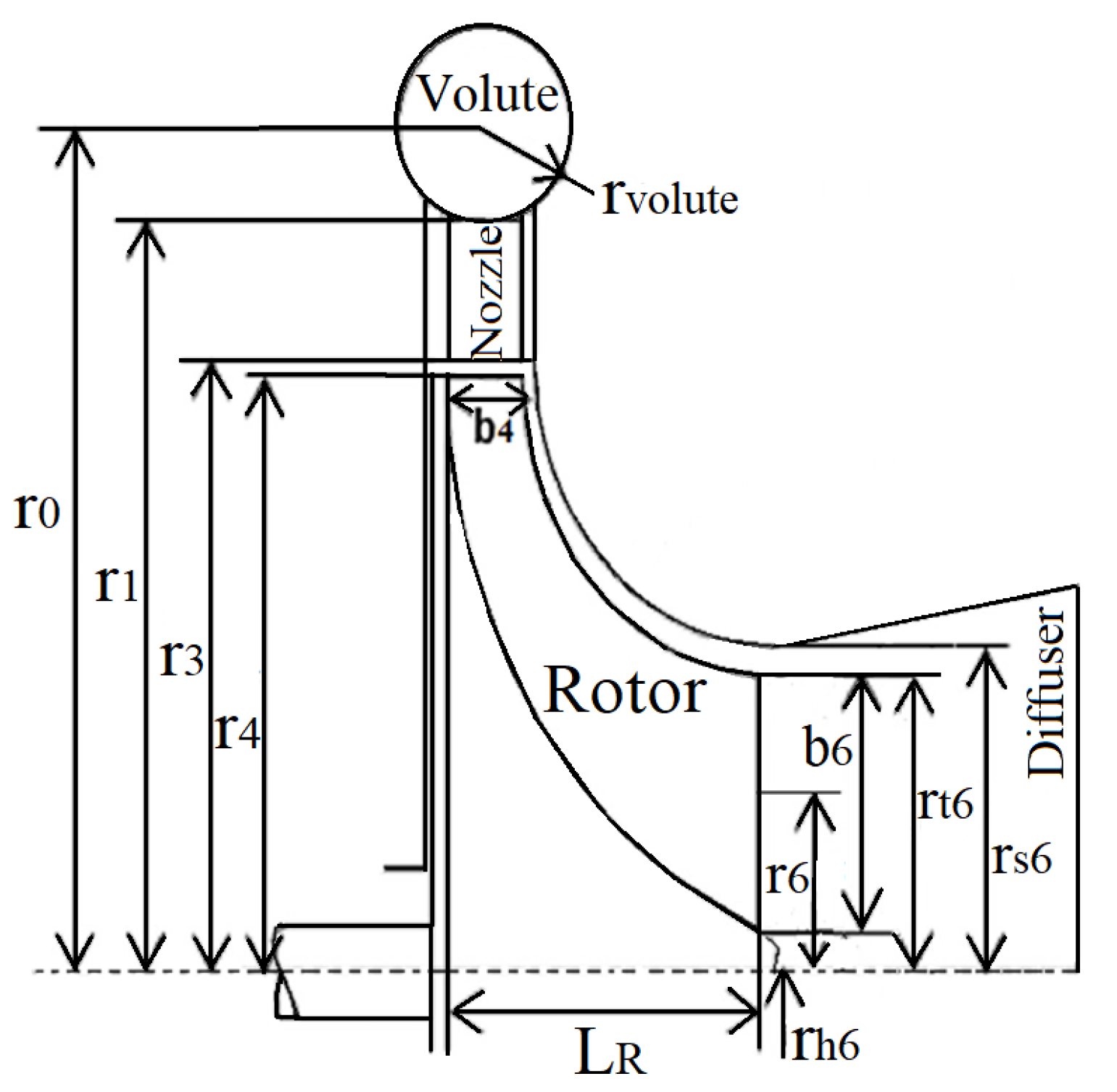
From the 3D turbine design, turbine efficiency curves were constructed under design and off-design conditions to analyze the parameters with the strongest effect on the design conditions. Additionally, in this step, the variations of absolute and meridional velocity, pressure, and Mach number in the turbine rotor and nozzle were analyzed to identify the regions of these components that displayed a specific or unwanted behavior and that could be improved by subsequent optimization. Figure 2 shows some geometric parameters of the radial inflow turbine, which were subsequently used in different calculation procedures of the turbine design [41].
Based on the symbols presented in Figure 2 and following the sequence defined in the calculation algorithm shown in Figure 1, several steps were taken to achieve the objective of the method proposed in this study, as presented below. Thus, the initial step consisted of defining the equations, parameters, and considerations needed to model the rotor of a radial inflow turbine.

3. Rotor Model

The following three parameters are important for the analysis of this component [41]: the load coefficient, the flow coefficient, and the meridional velocity ratio. The load coefficient (ψ) is a measure of the turbine work and load, and this parameter is determined by Equation (1).
ψ = h 0 U 4 2 = C θ 4 U 4 ε C θ 6 U 4
where ( ε = r 6 / r 4 ). For a radial turbine, ψ values ranging from 0.6 to 1.4 can be used [41]. The flow coefficient is determined according to Equation (2) [41].
Φ = C m 6 U 4
For a radial turbine, the flow coefficient can be defined in the [0.2–0.5] range [40]. The third parameter is the meridional/velocity ratio ξ at the rotor outlet and inlet, which is defined according to Equation (3) [41].
ξ = C m 4 C m 6
According to Aungier [42], the ξ value can range from 0.67 to 1.
The minimum loss of kinetic energy in the rotor is achieved when the absolute angle of the fluid is zero. Under this condition, the absolute velocity of the fluid at the turbine outlet is its minimum [43,44]. For C θ 6 = 0 , the load coefficient is calculated using Equation (4).
ψ = C θ 4 U 4
The circumferential rotation speed at the rotor inlet U 4 is determined according to Equation (5).
U 4 = h 0 ψ
Thus, the tangential component of absolute velocity at the rotor inlet ( C θ 4 ) can be calculated according to Equation (6).
C θ 4 = ψ U 4
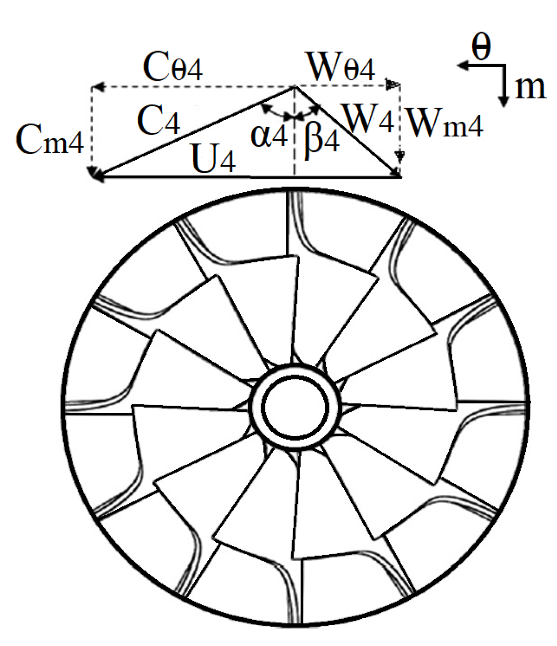
Figure 3 shows the fluid velocity triangle at the rotor inlet for β 4 < 0 .
From the parameter Φ , Equation (2), the meridional component of absolute velocity at the rotor outlet can be determined ( C m 6 ) using Equation (7).
C m 6 = Φ U 4
The meridional component of absolute velocity at the rotor inlet ( C m 4 ) is determined using Equation (8).
C m 4 = ξ C m 6
From Equations (6) and (8), the absolute velocity at the rotor inlet C 4 is determined using Equation (9).
C 4 = C m 4 + C θ 4
Using the velocity triangle of Figure 3, the absolute flow angle of the fluid at the rotor inlet α 4 is determined using Equation (10).
α 4 = t a n 1 C θ 4 C m 4
Additionally, the relative flow angle of the fluid at the rotor inlet β 4 is determined using Equation (11).
β 4 = t a n 1 C θ 4 U 4 C m 4
With β 4 , the relative velocity at the rotor inlet ( W 4 ) can be determined using Equation (12).
W 4 = C m 4 cos β 4
The meridional component of the relative velocity at the rotor inlet W m 4 is determined using Equation (13).
W m 4 = C m 4
The tangential component of the relative velocity at the rotor inlet W θ 4 is determined using Equation (14).
W θ 4 = W 4 sin β 4
Assuming that the volute flow is adiabatic, and since no research has been conducted on this component, the total enthalpy through the nozzle is conserved, and the enthalpy at the nozzle outlet ( h 03 ) is equal to the total enthalpy at the turbine inlet ( h 01 ). Thus, the total enthalpy at the rotor inlet is equal to the total enthalpy at the nozzle outlet h 04 = h 03 . Hence, the total pressure at the turbine inlet can be determined using Equation (15).
P 04 = P 01 ρ 01 h r e a l 1 η t u r b i n e 4 η t u r b i n e
With the values of h 04 , C 4 , and the enthalpy loss coefficient at the nozzle ( Ϛ b v a l u e   r a n g i n g   f r o m   0.05   t o   0.15 [46]), the following parameters can be determined: h 4 , h 4 i s e , I 4 , M a 4 , M a 4 r e l , and P 4 .
The parameters, such as inlet blade thickness (tb4), outlet blade tip thickness (t6t), outlet blade root thickness (t6h), outlet blade root radius (rh6), the axial length of the rotor (LR), and the number of blades ( Z R ) are determined using the following equations [42,47]:
t b 4 = 0.04   r 4
t 6 t = 0.01   r 4
t 6 h = 0.02   r 4
r h 6 = 0.18   r 4
L R = 1.5 r s 6 r h 6
Z R = π 30 110 α 4 tan α 4
According to the equation proposed by Balje [48], the radius from the axis of rotation of the turbine to the rotor inlet r 4 can be determined using Equation (22) [48].
r 4 = U 4 ω
Additionally, from the continuity equation, the area necessary for fluid flow at the rotor inlet can be determined using Equation (23).
A 4 = m ˙ ρ 4 C m 4
The rotor inlet blade height b 4 can be determined using Equation (24).
b 4 = A 4 2 π r 4 Z R e b 4
Figure 4 shows the velocity components at the rotor outlet.
The value of the circumferential rotation speed at the rotor outlet ( U 6 ) is determined using Equation (25).
U 6 = ε U 4
The absolute velocity at the rotor outlet ( C 6 ) can be expressed using Equation (26), and the meridional component of the relative velocity at the rotor outlet ( W m 6 ) can be determined using Equation (27).
C 6 = C m 6 cos α 6
W m 6 = C m 6
The tangential component of the relative velocity at the rotor outlet ( W θ 6 ) can be determined using Equation (28).
W θ 6 = C θ 6 U 6
From Equations (7) and (28), the relative velocity W 6 can be determined according to Equation (29).
W 6 = C m 6 2 + W θ 6 2
The following parameters can be determined from the value of the turbine pressure ratio and s 01 : h 06 , s 06 , P 06 , h 6 , ρ 6 , P 6 , and T 6 . The rotor outlet area (A6) is calculated using Equation (30).
A 6 = m ˙ c r o ρ 6 C m 6
Additionally, the values of the radii at the rms point ( r r m s 6 ) and rotor outlet blade tip ( r s 6 ), defined in Figure 2, can be determined using Equations (31) and (32).
r s 6 = A 6 π + r h 6 2
r r m s 6 = r h 6 2 + r s 6 2 2
With the ( r s 6 ), ( r s 6 ), ( r r m s 6 ), and ω values, the blade circumferential speeds ( U h 6 ), ( U r m s 6 ), and ( U s 6 ) can be determined using Equations (33)–(35).
U h 6 = ω r h 6
U r m s h 6 = ω r r m s 6
U s 6 = ω r s 6
Additionally, the following respective relative velocity components and relative angles of the flow at the impeller outlet can be determined using the parameters presented above:
W h 6 = C 6 2 + U h 6 2
W r m s 6 = C 6 2 + U r m s 6 2
W s 6 = C 6 2 + U s 6 2
β h 6 = t a n 1 U h 6 C 6
β r m s 6 = t a n 1 U r m s 6 C 6
β s 6 = t a n 1 U s 6 C 6
Finally, the absolute and relative Mach numbers M a 6 and M a 6 r e l are calculated to determine the fluid behavior at the rotor outlet.

4. Nozzle Model

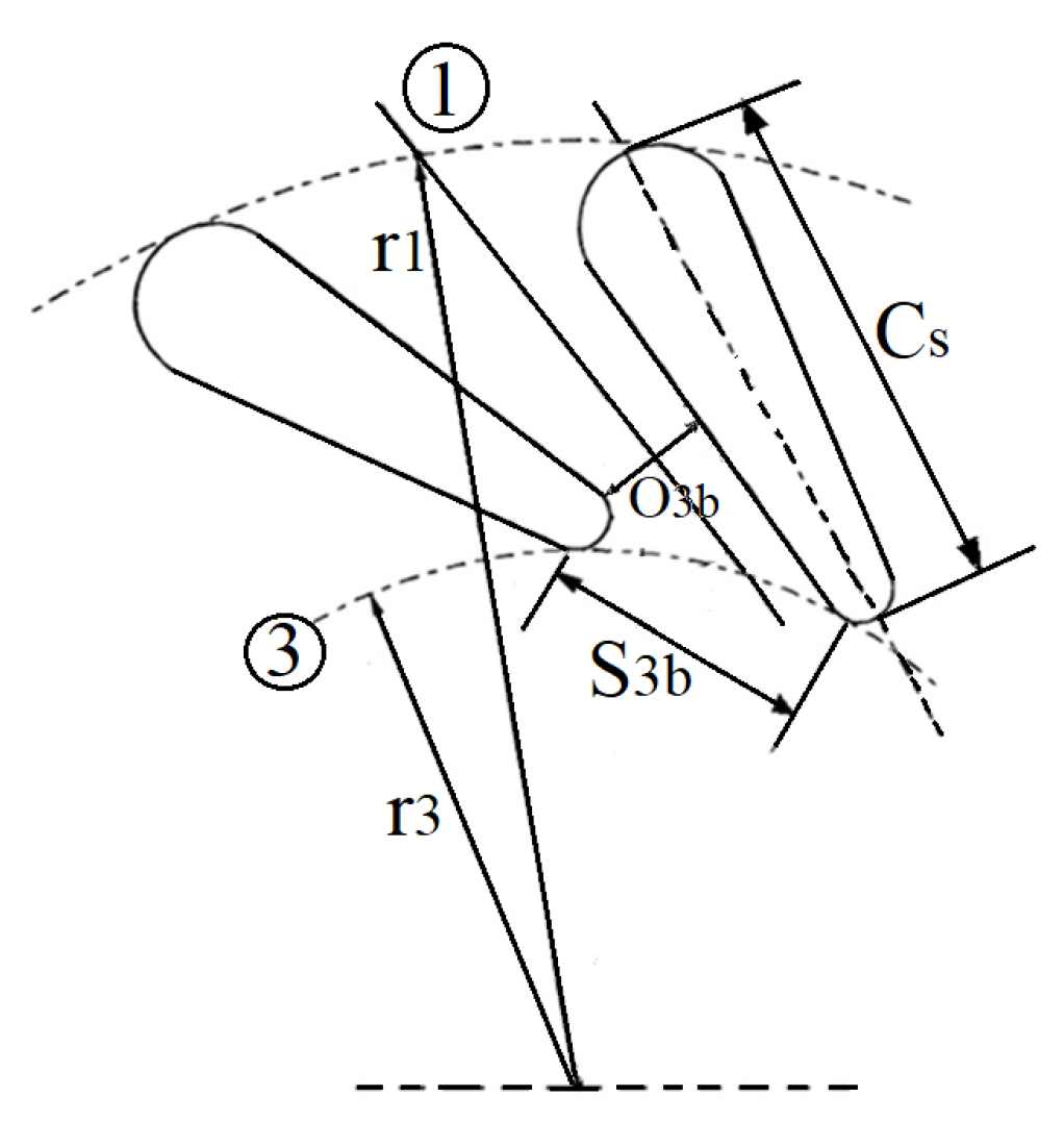
In radial turbine projects, the design of the fixed blades (the nozzle) must be correctly analyzed. Therefore, parameters (Figure 5), such as the distance between nozzle blades ( s 3 b ) , nozzle throat width ( o 3 b ), and the number of stator vanes ( Z b ) must be assessed. According to Venturta et al. [49], ( Z b ) can be determined using Equation (42).
Z b = 2 π r 1 C s S s
where Ss is a nozzle design parameter [1.0–2.8] [50] and C s is the nozzle blade chord. The nozzle blade chord ( C s ) is calculated using Equation (43) [50].
c s 2 + 2 r 1 c s cos α 3 + r 3 2 r 1 2 = 0
This equation is only valid if the length of the blade surface is equal to the length of the blade chord, which applies to blades without curvature.
The distance between the nozzle outlet ( r 3 ) and the rotor inlet ( r 4 ) is determined using Equation (44), considering ( α 3 = α 4 ) [41,51].
r = K I b 4 cos α 3
where r is the distance between the nozzle outlet and the impeller inlet ( r = r 3 r 4 ). Watanabe et al. [51] suggested that the maximum efficiency of a radial turbine is reached at K I = 2 .
The nozzle inlet radius ( r 1 ) is calculated to solve Equation (43). This parameter can be determined under the design condition defined by Equation (45) [52].
r 1 = 1.3 r 4
With the ( α 3 ), ( r 3 ), and ( r 1 ) values, ( C s ) can be determined using Equation (43) and Z b using Equation (42). The distance between nozzle blades ( s 3 b ), the nozzle throat width ( o 3 b ), and the nozzle inlet flow angle ( α 1 ) is determined using Equations (46)–(48) [42].
s 3 b = 2 π r 3 Z b
o 3 b = s 3 b cos ( α 3 )
α 1 = t a n 1 sin ( α 3 ) c s r 3 + cos ( α 3 )
As shown in Figure 5, the inlet ( b 1 ) and outlet ( b 3 ) nozzle blade heights are equal to the rotor inlet height ( b 4 ). Thus, the volute inlet area ( A 0 ) can be determined using Equation (49) [52].
A o = π   r 0 r 1 2
The nozzle inlet area is calculated using Equation (50).
A 1 = 2 π   r 1   b
where r 0 is the volute inlet radius that is calculated using Equation (51) [52].
r 0 = 2   r 1
The volute inlet velocity is determined using Equation (52).
C 0 = m ˙ c r o ρ 0 A 0
Thus, the velocity triangle at the nozzle inlet can be determined as follows:
C θ 1 = C 0 r 0 r 1
C m 1 = C 0 A 0 A 1
C 1 = C θ 1 2 + C m 1 2
The C 3 velocity is determined using Equation (56).
C 3 = m ˙ c r o A g ρ 3 1 f b
Additionally, C m 3 and C θ 3 are calculated using Equations (57) and (58), respectively.
C m 3 = C 3 cos ( α 3 )
C θ 3 = C 3 sin ( α 3 )
From the parameters calculated above, the following values were determined: h 1 , M a 1 , h 3 , h 3 i s e , P 3 , and M a 3 .

5. Volute Model

Volute design methods are based on the assumption of constant angular momentum (or free vortex) or of constant mean velocity through the volute [53]. Thus, the behavior of the volute can be characterized using Equation (59) or (60).
r C θ = Constant = K
R v C 4 = C mean = Constant
where the mass flow in the azimuthal direction (ψ) is calculated using Equation (61).
m ˙ ψ = m ˙ cro 1 ψ 2 π
Designing the volute requires determining the radius of the azimuthal angle or blade loading coefficient (ψ), which can be calculated using Equation (62) [41].
r ψ = m ˙ cro r 0 ρ 01 C 0 r 0 π 1 ψ 2 π
After modeling the main components of the radial turbine, such as the rotor, nozzle, and volute, the following concepts will be defined to evaluate turbine losses.

6. Radial Turbine Losses

Radial turbine rotor, nozzle, and volute losses will be described in this model. These losses can be expressed as a function of enthalpy drop through the component; then, the isentropic efficiency of the turbine can be calculated using Equation (63) [45,50].
η ise = h 0 h 0 + h p

6.1. Rotor Losses

In this section, a simplified model is presented given the complexity of simulating the real three-dimensional behavior of the flow inside the rotor [41].
Tip clearance losses: These losses can be calculated using the equation proposed by Rahbar et al. [45], which is Equation (64).
h ftp = U 4 3 Z R 8 π 0.4 ε x C x + 0.75 ε r C r 0.3 ε x ε r C x C r
C x = 1 r t 6 r 4 C m 4 b 4
C r = r t 6 r 4 L R b 4 C m 6 r 6 b 6
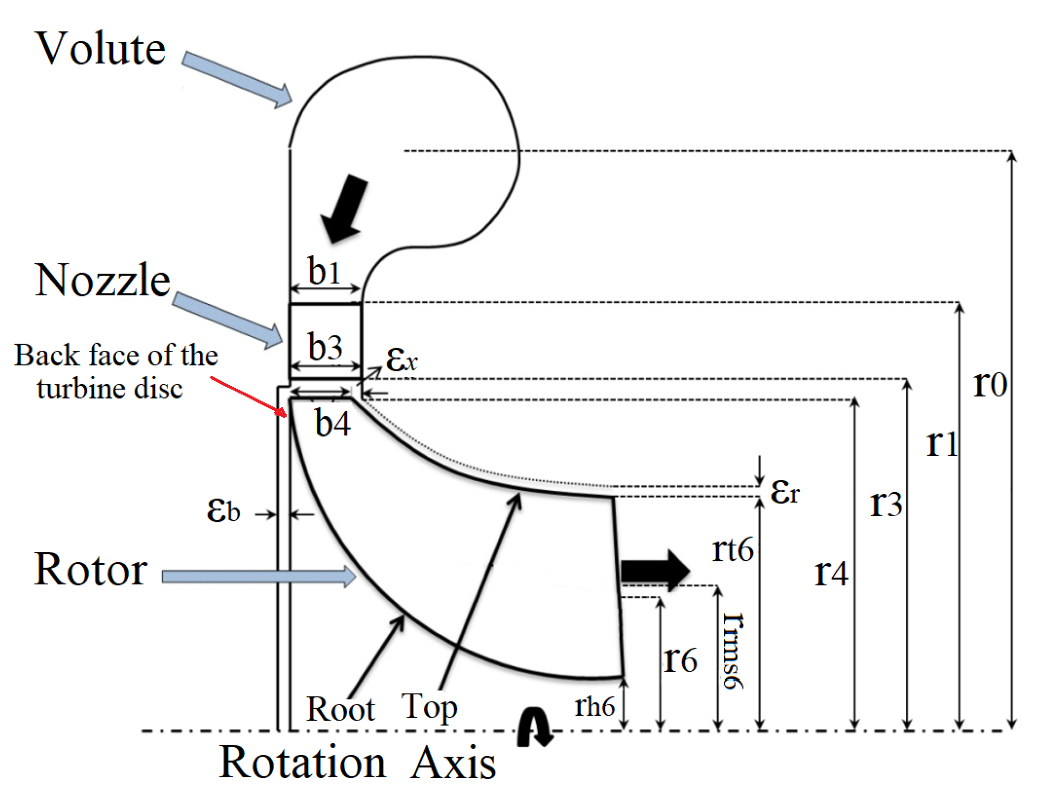
where ε x and ε r are the axial and radial distances in the blade tip, calculated with Equation (67).
ε x = ε r = 0.04 r t 6 r h 6
Figure 6 shows a simplified schematic representation of the radial turbine, the main design radii, and the axial and radial clearances.

6.1.1. Friction Losses

These losses are located in the turbine rotor backface and are caused by the working fluid flow through the rotor backface [35]. They can be calculated using Equation (68) [45,54].
h a t = f r 1 + 0.075 R e 0.25 D h i d 2 r c R e D 4 2 r c 0.05 W 4 + W t 6 + W h 6 2 2 2 L h i d D h i d
where f r is the friction factor, which is determined using Equation (69) [55].
f r = 8 8 R e 12 + 2.457 l n 1 7 R e + R R 16 + 37530 R e 16 1.5 1 12
R e = U 4 b 4 ρ 4 μ 4 + U 6 r t 6 r h 6 ρ 6 μ 6 2
The hydraulic length ( L h i d ) and diameter ( D h i d ) are calculated using Equations (71) and (72), respectively [45].
L h i d π 2 r 4 r t 6 + b 4 2 2 + r t 6 r h 6 2 2 2
D h i d = 0.5 4 π b 4 r 4 2 π r 4 + Z R b 4 + 2 π r t 6 2 r h 6 2 π r t 6 r h 6 + Z R r t 6 r h 6
where R e is the mean Reynolds number between the turbine inlet and outlet, and RR is the relative wall roughness. Rahbar et al. [45] demonstrated that the value of this parameter can be considered equal to 0.0002 m [42,45].

6.1.2. Outlet Losses

According to [35,46,50], outlet losses can be determined using Equation (73).
h s = C 6 2 2
Incidence losses: Incidence losses can be determined when the incidence angle differs from zero, using Equation (74) [56].
h i = 0.5 W 4 2 s i n n i
The angle of incidence is calculated using Equation (75) [41].
i = β 4 β 4 _ o p t i m u m
The optimal value of the rotor inlet fluid angle ( β 4 _ o p t i m u m ) can be calculated using Equation (76) [36].
β 4 _ o p t i m u m = 90 t a n 1 1.98 U 4 C m 4 Z R

6.1.3. Aerodynamic Load Losses

These losses are calculated as a function of enthalpy drop using Equation (77) [49].
h w = k f ρ U 4 2 r 4 2 2 m ˙ W 6 2
where k f represents the torque coefficient, a parameter that can be calculated using Equations (78) and (79) [57].
k f = 3.7 ε c p r 4 0.1 R e 0.5 F o r   R e < 10 5
k f = 0.102 ε c p r 4 0.1 R e 0.2 F o r   R e > 10 5
where ε c p is the blade backface clearance or gap. According to Erbas et al. [58], ε c p = 0.1   m m [58].

6.1.4. Trailing Edge Loss

This loss can be determined using Equation (80) [41].
h = 0.5 C m 5 C m 6 2

6.2. Nozzle Losses

In this study, the enthalpy drop through the turbine nozzle will be modeled by calculating the nozzle friction loss, according to Equation (81) [45].
h b = 4 f r C b 2 L h i d _ b D h i d _ b
L h i d _ b = r 1 r 3
d h i d _ b = 0.5 8 π r 1 b 4 cos α 1 4 π r 1 + 4 π b 4 r 1 σ b + 8 π r 3 b 4 cos α 3 4 π r 3 + 4 π b 4 r 3 σ b
R e b = U 1 b 4 ρ 1 μ 1 + U 3 b 4 ρ 3 μ 3 2
where C b is the mean absolute velocity between the nozzle inlet and outlet, L h i d _ b is the nozzle hydraulic length, D h i d _ b is the nozzle hydraulic diameter, and R e b is the mean Reynolds number. The nozzle width is considered constant and equal to b 4 , and the nozzle solidity ( σ b ) is equal to 1.35, according to [59].

6.3. Volute Losses

Volute losses are calculated using Equation (85).
h v o l u t e = k v o l u t e C 1 2 2

7. 3D Radial Turbine Design

Using the preliminary model of the radial turbine, the geometric parameters of the volute, nozzle, and rotor are determined. From this model, the necessary parameters for the development of the 3D turbine design are determined. For each working fluid (R-245fa, R-141b, and R-123), a one-dimensional design of the turbine was developed, followed by a 3D design in CFX-ANSYS. The working fluids were chosen for their low ozone layer depletion potential, i.e., R-245fa (0), R-141b (0.12), and R-123 (0.022). Additionally, some of them have been used for electricity generation in ORC systems. In terms of global warming potential, these fluids present acceptable values in relation to other fluids, i.e., R-245fa (950), R-141b (713), and R-123 (76) [60]. These fluids were selected from a group of fluids used in different published studies on heat recovery systems from organic Rankine cycles [50,61,62].
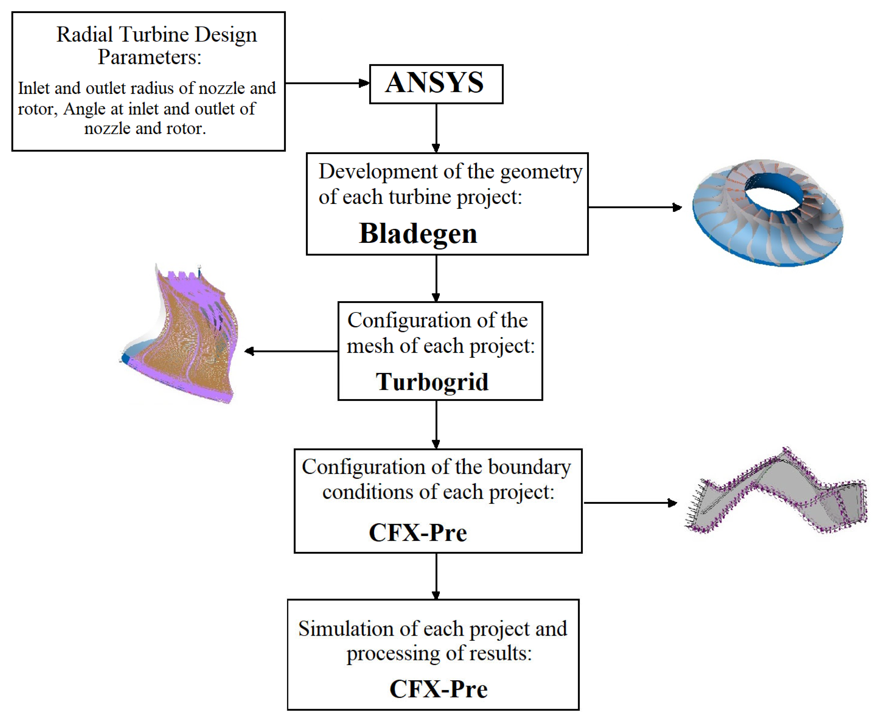
Figure 7 shows a simplified flowchart of the method applied to develop the 3D turbine designs.
During the 3D project, each turbine geometry was generated in ANSYS Bladegen®, the meshes were generated and configured in ANSYS Turbogrid®, and the boundary conditions of each case analyzed and simulated in this study were defined using the tool CFX-Pre®. In addition, the simulation control conditions were set in CFX-Pre® for each case developed in this study. After all the steps shown in Figure 7, the 3D geometries of the ORC turbine nozzle and radial rotor were obtained based on the working fluid and operating conditions defined for each project. The simulations performed in the module CFX-Pre® yielded pressure, velocity, and Mach number profiles across turbine components.

8. Validation of One-Dimensional Mathematical Models of the Radial Turbine

Table 1 outlines the radial turbine design parameters used to validate the one-dimensional radial turbine model.
Table 2 outlines the parameters compared in the validation of the one-dimensional model of the radial turbine. For this purpose, we used the operating and design parameters of a radial turbine proposed by Paltrinieri [52] for a 267 kW turbine.
The comparison of the parameters in the validation process (Table 2) showed maximum differences in the relative Mach number at the rotor inlet (Ma4′) and in the Mach number at the nozzle inlet (Ma1). These values can be explained by the differences in the approaches implemented in the calculation algorithm between this study and the study by Paltrinieri [52]—for example, in the nozzle and volute design and in the model of turbine losses, in addition to the design considerations that were not fully defined in the reference from the literature. Excluding the rotor inlet blade height (b4), for which the difference from the reference value was 7%, the other parameters evaluated showed differences of less than 5%.

9. Radial Turbine Design Results

The main results of the preliminary radial turbine designs for R-245fa, R-141b, and R-123 are presented in this section. Subsequent analyses were performed to improve the geometries and boundaries of each turbine component (nozzle and rotor) and enhance their efficiency. The 3D design of these turbines was developed based on the parameters determined at this stage. Table 3 outlines the parameters used to develop the one-dimensional design of each turbine.
Table 3 presents the results found after completing all steps of the radial turbine preliminary design (see Figure 6) and from the subsequent analysis of the improvements of each of the resulting turbine configurations. For this analysis, a reference power output (9 kWe) was defined and based on data from the one-dimensional model, the necessary adjustments were made to obtain the best behavior of the working fluid in each configuration. This required introducing some modifications to the geometries of each configuration, thereby leading to differences between the power output from each turbine configuration and the value defined as the reference power.
Based on these, the main aerodynamic design parameters of the radial turbine were determined for the three organic fluids selected for this study. The radial turbine designs developed in this study were mainly analyzed for the geometric parameters of their nozzle rotors because they are often considered the most critical turbine components. As presented in the mathematical modeling section, the volute design was briefly analyzed. Different studies found in the scientific literature have focused their analysis on the characterization and modeling of the turbine nozzle and rotor [35,63,64]. Table 4 outlines the geometric and operating parameters of the turbine nozzle and rotor designs.
The parameters presented in Table 4 made it possible to start constructing the nozzle-rotor passage geometries of the three turbines proposed in this study. In the first phase, the nozzle and rotor geometries were created on the Bladegen-ANSYS platform. The mesh configuration step of each component begins from each geometry. Mesh creation is a critical phase in the development of the project because mesh quality directly affects the behavior of fluids within each component and the efficiency of the equipment.
Figure 8 shows the distribution of turbine shroud, rotor, and nozzle losses of the projected turbines operating with R-245fa, R-141b, and R-123 with the characteristics outlined in Table 4.
The results shown in Figure 8 highlight that, for radial inflow turbine designs, the greatest losses occur at the nozzle, clearances, and rotor passage. For the three radial inflow turbine configurations, the lowest losses occur at the channel outlet, volute, and disc (friction). These results show the high impact that the nozzle design has on the working fluid and its flow regime along this component and its transition to the rotor. Another important aspect to verify is the spacing between the turbine components to avoid excessive energy loss through these clearances. Finally, the sensitivity analysis showed that optimized turbine rotor projects allow for reductions in the losses present in the turbine rotor.
To ensure the quality of the mesh of each project, an independent analysis must be performed for each mesh to assess the quality of the findings in each project. Table 5 presents the independent studies performed for each radial turbine design.

10. Efficiency Characteristics of the Radial Turbine Nozzle-Rotor Set

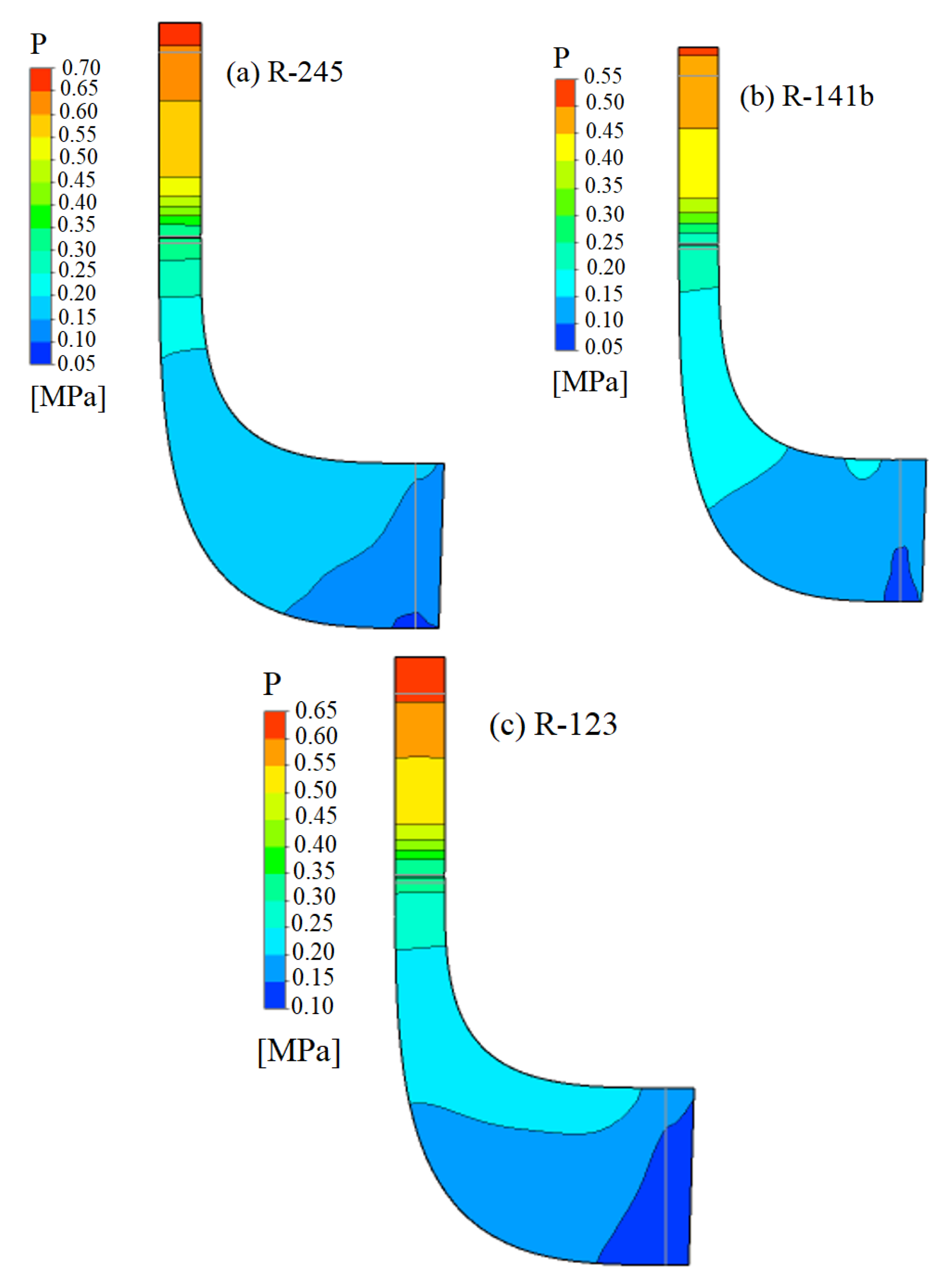
The mesh geometries, configuration and evaluation, and the definition of the boundary conditions and control parameters of the simulations were performed for the designs defined in Table 4 before evaluating the results from each simulation. Figure 9 shows pressure boundaries from the rotor inlet to the outlet in the meridional plane of the nozzle-rotor set.
The pressure boundaries shown in Figure 9 highlight a pressure drop from the nozzle inlet to the impeller outlet in each design. Moreover, there is no uniform pressure distribution among the designs. This lack of uniformity is mainly associated with the physicochemical characteristics of each working fluid used and with the geometric configuration of each turbine design (Table 4). For the pressure distribution analysis along the nozzle up to the rotor outlet, a decrease in the pressure value of 21.4% was observed for the turbine project with R-245fa, 27.3% for the turbine with R-141b and 23.1% for the turbine with R-123.
Figure 10 shows Mach number boundaries in the nozzle-rotor set at 50% nozzle and rotor blade height.
Figure 10 shows the absolute Mach number boundaries in the nozzle passage and the relative Mach number in the rotor for the radial turbine operating with R-245fa, R-141b, and R-123. In general, Figure 10 shows Mach numbers lower than 1 for the three designs, in addition to small areas with Mach numbers equal to 1 in the nozzle outlet. As this condition does not occur along the nozzle outlet surface, this behavior of the fluid can be considered within the subsonic regime because similar behaviors were presented in other studies on this component [31]. This type of radial turbine can work with a Mach number of up to 1.5 [41].
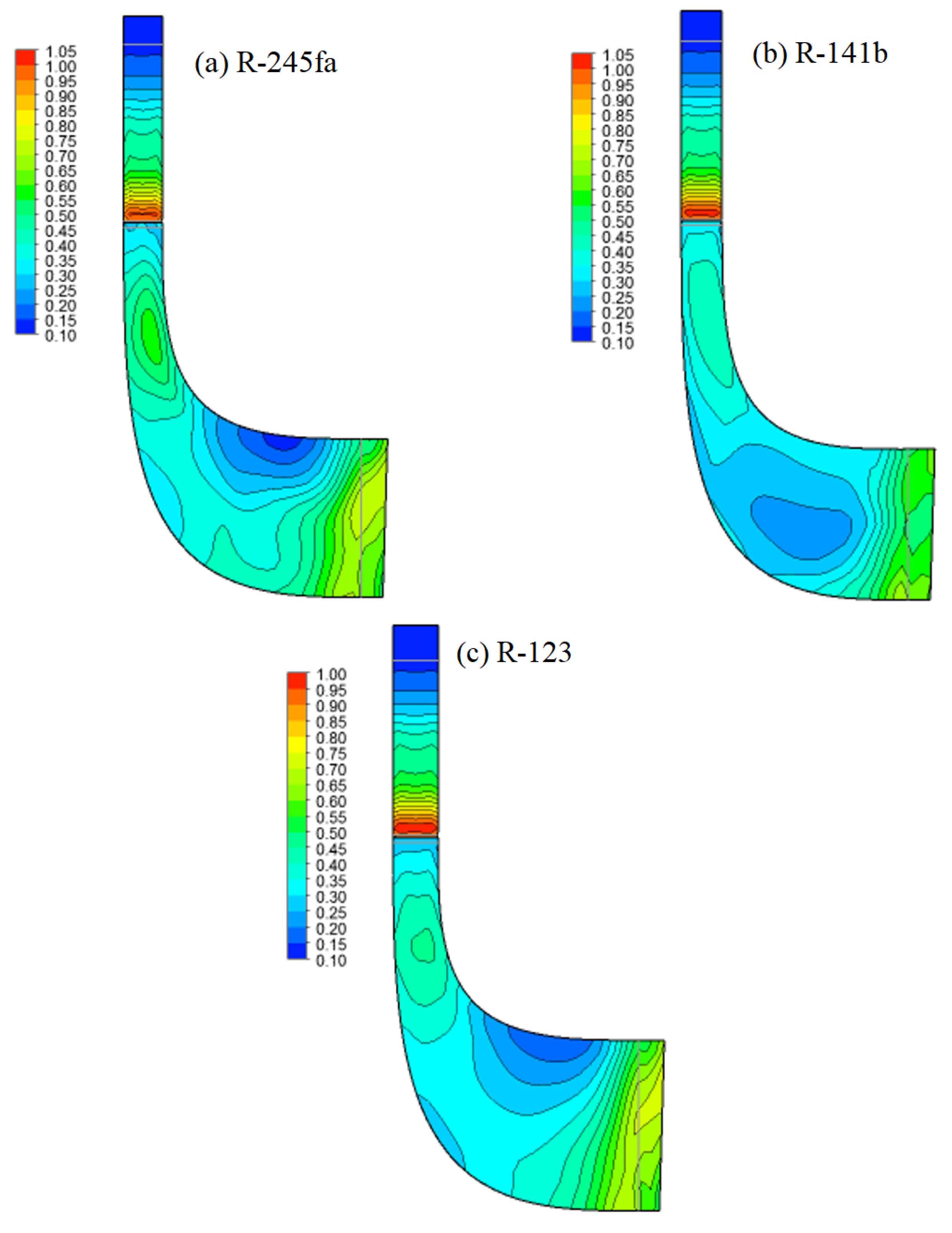
Figure 11 shows Mach number boundaries in the meridional plane of the radial turbine nozzle-rotor set.
The boundaries identify small areas of the nozzle outlet with a Mach number equal to 1 for projects with R-245fa and R-141b. In general, the distribution of the Mach number along the nozzle and rotor boundary defines the subsonic flow. In the case of the three turbine projects, the highest Mach number values (close to or equal to 1) are observed at the rotor inlet. This is related to the effect that must be generated by the turbine nozzles, which is to generate a transformation of energy in the form of enthalpy to kinetic energy. Then, a decrease in the value of this parameter is observed along the rotor, reaching values ranging from 0.65 to 0.3.
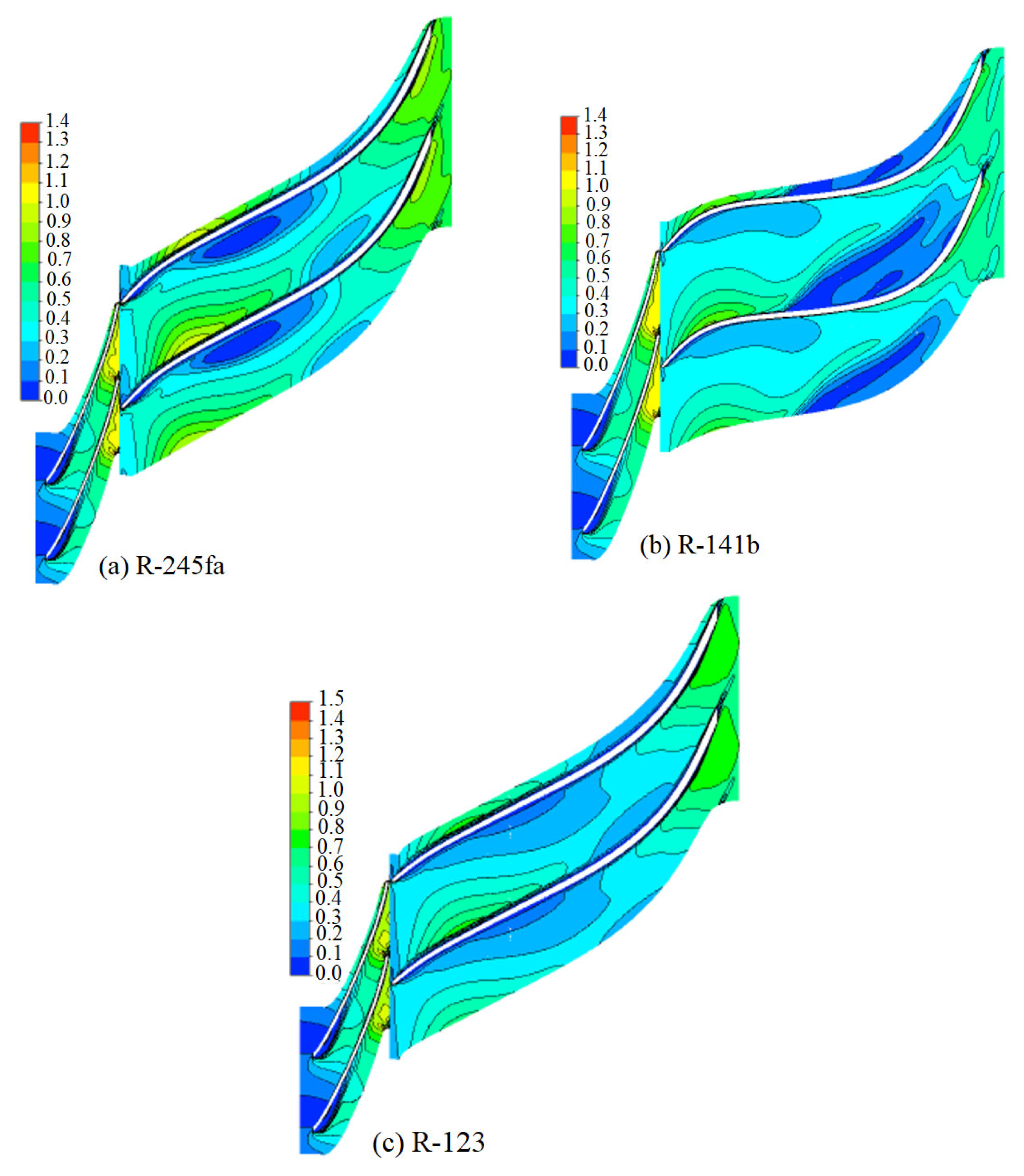
Figure 12 shows the distribution of absolute velocity along the nozzle and rotor passage at 50% meridional plane height.
Figure 12 shows a small area with the recirculating flow in the R-245fa project and a larger and sharper area with this behavior in the R-141b project. In general, the fluid presents a guided flow through the nozzle and the rotor. In the R-123 project, the fluid is perfectly guided, without disturbing areas inside the component. In the R-141b turbine (Figure 12b), the fluid recirculation area shows a separation of the fluid boundary layer on the rotor blade surface. When comparing the three turbine projects and their profiles, it is observed that in the case of the profile of the project with R-141b (Figure 12b), the angles obtained for this profile are much steeper in relation to the turbine projects with r-245fa and R-123.
Following the radial turbine nozzle and rotor results under design conditions, the next stage of this work consisted of analyzing the behavior of this component under off-design conditions. The main results from this analysis are presented below.

11. Characteristic Curves of Radial Turbines

To determine the behavior of the turbines projected in this study under off-design conditions, the behavior of each turbine was simulated for different pressure ratio values, maintaining the rotation speed constant. The other method consisted of varying the turbine rotation speed while keeping the pressure ratio constant. The parameters for the design conditions were presented previously, in the section on the one-dimensional turbine project (Table 3).
Figure 13 shows the variation in the efficiency and power of the radial turbine operating with R-245fa as a function of the pressure ratio.
For the range of pressure ratios evaluated in the R-245fa turbine design, the minimum efficiency was 41.44% at a pressure ratio of 2.71, and the maximum performance was 76.12% at a pressure ratio of 5.71, with the latter corresponding to the design condition for this turbine (black point on the performance curve). This analysis shows that turbine performance increases with the pressure ratio until reaching a maximum point, after which turbine performance decreases. This decrease in efficiency results from the increase in turbine rotor and nozzle losses. Turbine power increases with the pressure ratio due to the increase in fluid expansion through the turbine for each increase in the pressure ratio and, therefore, in the work generated by this component. Under these conditions, the minimum and maximum power were 2.5 kW at a pressure ratio of 2.71 and 9.42 kW at a pressure ratio of 7.71. At the design point, the power generated by the turbine was 8.76 kW (black point on the power curve).
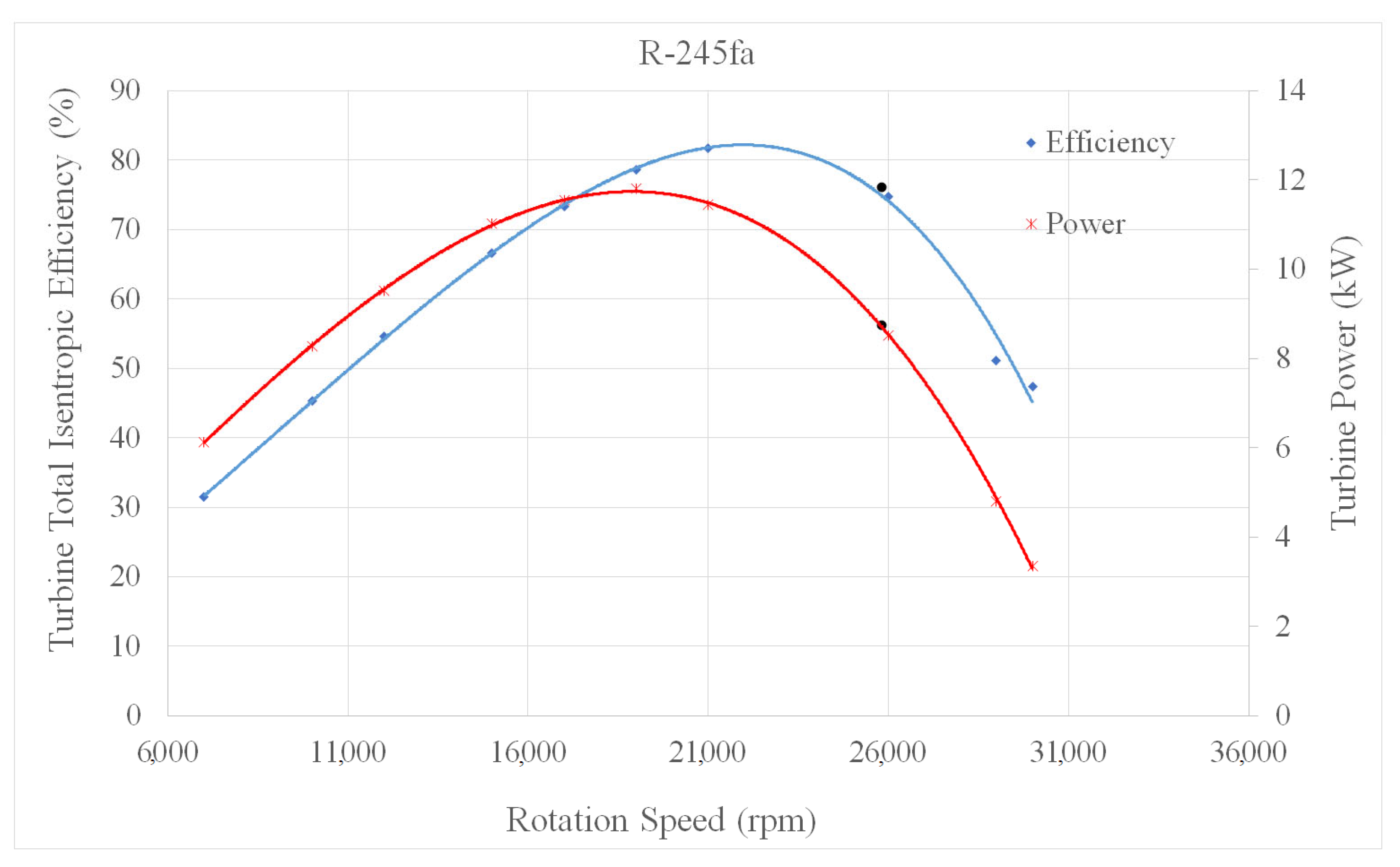
Figure 14 shows the variation in the efficiency and power of the radial turbine operating with R-245fa as a function of the rotation speed.
As shown in Figure 14, turbine efficiency and power initially increased with the rotation speed, until it peaked. From this maximum point, turbine efficiency and power decreased with the increase in the rotation speed. This effect was caused by the increase in disturbances in flow lines as they pass through the nozzle and rotor. During the simulations, instability was observed in the behavior of some conditions of the designs. During this turbine operating range, (nozzle and rotor) losses increased, and in some cases, the fluid presented a turbulent behavior. For the speed range under study, the minimum and maximum efficiencies were 31.54% (7000 rpm) and 81.76% (21,000 rpm), while the minimum and maximum power were 3.35 kW (30,000 rpm) and 11.8 kW (19,000 rpm), respectively.
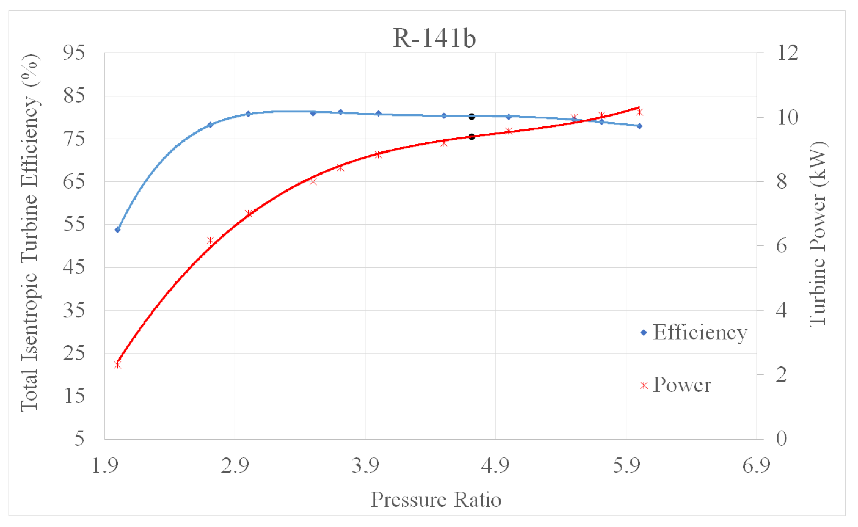
Figure 15 shows the variation in the efficiency and power of the radial turbine operating with R-141b as a function of the pressure ratio.
When the pressure ratio values were tested for the turbine operating with R-141b, the minimum efficiency was 53.72% at a pressure ratio of 2, and the maximum efficiency was 81.26% at a pressure ratio of 3.71. In the efficiency curve, the black dot defines the design condition with an efficiency of 80.3% and a power of 9.41 kW at a pressure ratio of 4.71. The minimum turbine power was 2.3 kW at a pressure ratio of 2, and the maximum power was 10.2 kW at a pressure ratio of 6. The efficiency and power of the turbine operating with R-141b and R-245fa varied similarly as a function of the pressure ratio.
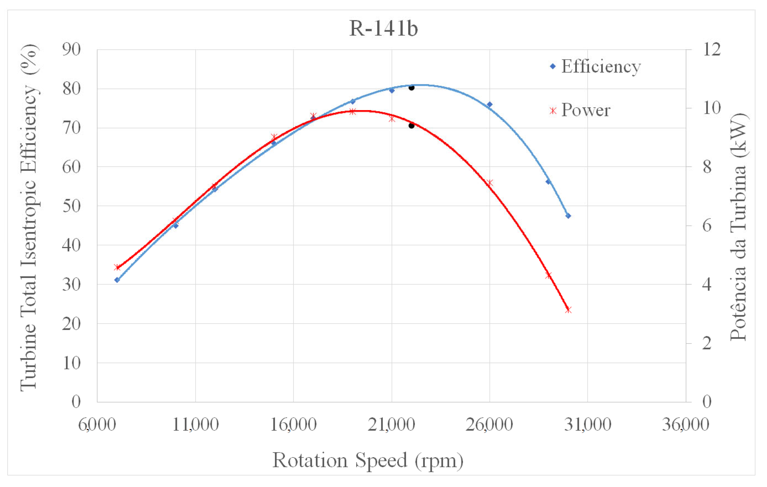
Figure 16 shows the variation in the efficiency and power of the radial turbine operating with R-141b as a function of the rotation speed. As described for R-245fa, the efficiency and power of the turbine operating with R-141b initially increased with the rotation speed until reaching a maximum point; then, these parameters decreased with the increase in the rotation speed. In the range of rotation speeds tested in this study, the minimum efficiency was 31.2% at a speed of 7000 rpm, and the maximum efficiency was 80.3% at a rotation speed of 22,000 rpm (at the design point). The minimum power value was 3.14 kW at a rotation speed of 30,000 rpm, and the maximum power value was 9.88 kW at a rotation speed of 19,000 rpm. For this fluid, the power at the design point (black dot) was 9.4 kW at a rotation speed of 22,000 rpm.
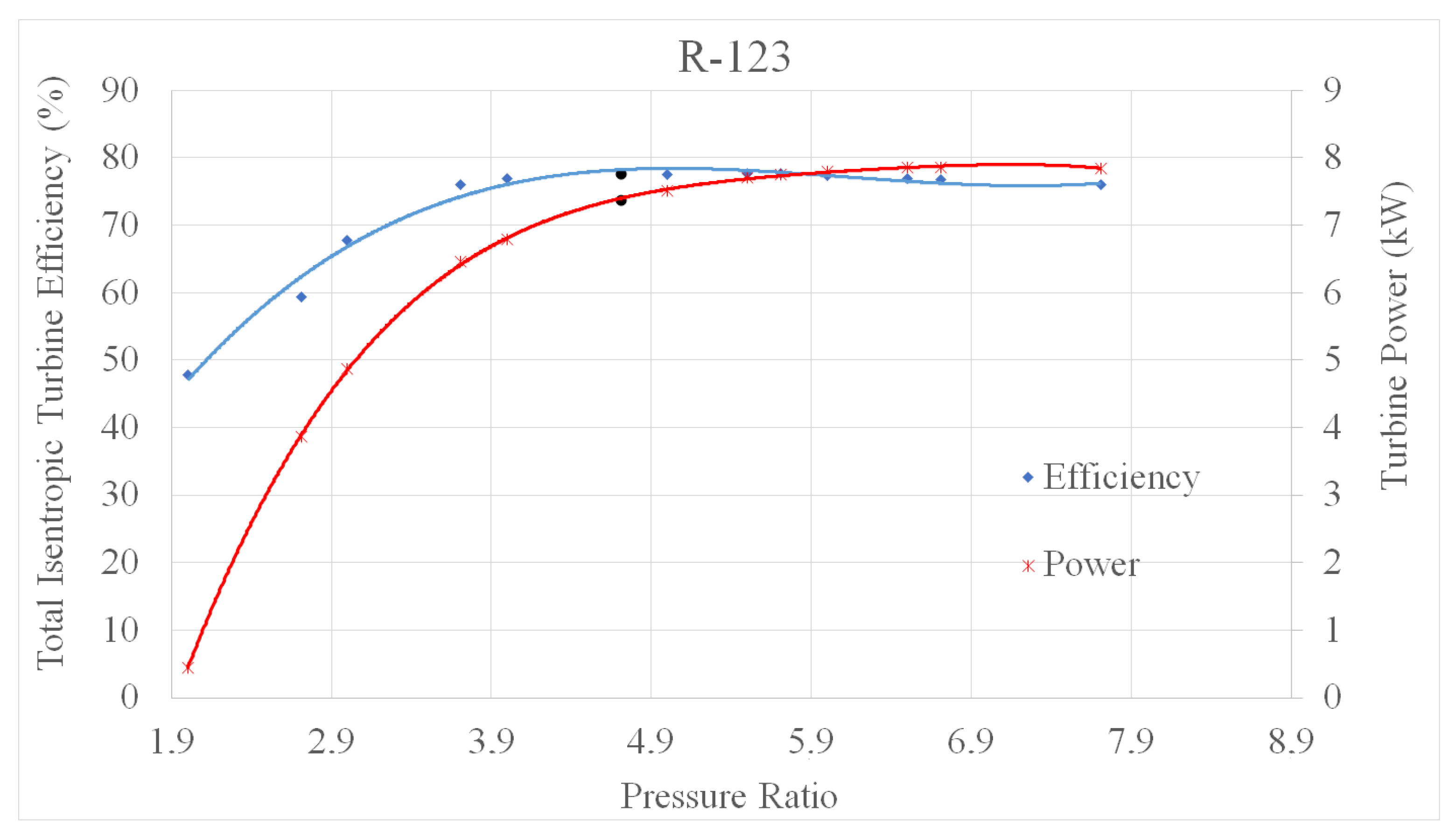
Figure 17 shows the variation in the efficiency and power of the radial turbine operating with R-123 as a function of the pressure ratio.
As shown in Figure 17, the turbine operating with R-123 had the minimum efficiency of 47.82% at a pressure ratio of 2 and the maximum efficiency of 77.9% at a pressure ratio of 4. Based on the analysis of the variation in turbine power, this parameter reached the minimum value of 0.5 kW at a pressure ratio of 2 and the maximum value of 7.9 kW at a pressure ratio of 6.71. The design point for R-123 was defined by an efficiency of 77.6% and a power of 7.37 kW at a pressure ratio of 4.71 and a rotation speed of 24,000 rpm.
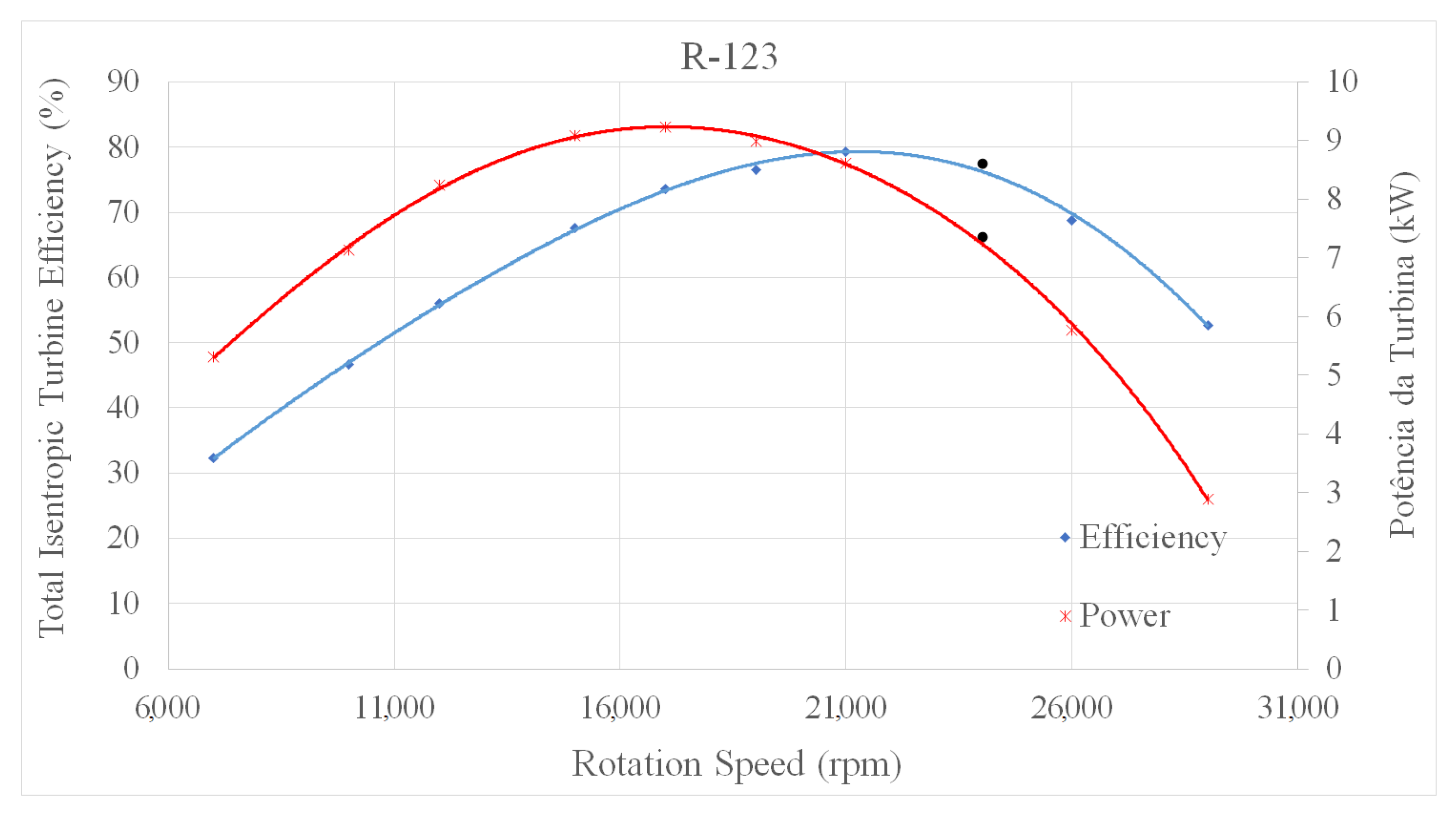
Figure 18 shows the variation in the efficiency and power of the radial turbine operating with R-123 as a function of the rotation speed.
In the range of rotation speeds tested for the turbine operating with R-123, turbine efficiency and power initially increased with the rotation speed until it peaked; from this maximum point of efficiency and power, these parameters decreased with the increase in the turbine rotation speed. Under these conditions, the minimum and maximum efficiencies were 32.3% at a rotation speed of 7000 rpm and 79.35% at a rotation speed of 21,000 rpm, while the minimum and maximum power were 2.89 kW at a rotation speed of 29,000 rpm and 9.24 kW at a rotation speed of 17,000 rpm, respectively.
Additionally, the efficiency results of turbine designs operating with the organic fluids R-245fa and R-141b, as well as the variation shown in the characteristic curves presented in this section, are similar to the findings reported by [65].
The results of the 3D design presented above indicate nozzle outlet obstruction when the radial turbine is operating with R-245fa and R-141b. Although changes were made in the design parameters, no considerable differences were found. This effect may be explained by the decrease in the area of some sections of the components. Therefore, performing a sensitivity analysis or optimizing the control points of the curves of the nozzle and rotor blade root and tip may directly help to improve the behavior of the Mach number.

12. Conclusions

This research is one of the few studies that show a complete analysis of the design of a radial turbine working in an organic Rankine cycle system for low-energy sources such as solar energy. This paper presents the thermal analysis, preliminary 1D design, and 3D simulations of the turbine under design and off-design conditions, operating with R-123, R-141b, and R-245fa. These fluids are recognized in the scientific literature as some of the most commonly used fluids for heat recovery in low- and medium-temperature processes.
The results show that nozzle, clearance, and rotor passage losses account for most energy losses in radial inflow turbines. Conversely, turbine rotor outlet, volute, and disc friction losses are the smallest energy losses. The results obtained in this section allowed us to determine that in a turbine project, efforts should be concentrated on the design of the nozzle, rotor, and clearances between different turbine components. This could lead to an optimization analysis to obtain detailed designs of this type of expander and its components.
Additionally, the 3D analysis of radial inlet configurations made it possible to establish strategies for improving the geometric configurations and aerothermodynamic parameters obtained in the one-dimensional design stage of each turbine analyzed in this study, which thereby improved energy use in this type of expansion system. The 3D analysis of turbines operating with R-123, R-141b, and R-245fa shows that the performance of the turbine operating with R-141b can be improved by adjusting the rotor curvature or angles, as shown in Figure 12b. The results of this study highlight the need to integrate optimization analysis into the design of this type of equipment. Moreover, in this study and under the conditions of a low-temperature source, improvement strategies were implemented in each turbine project, albeit without performing an in-depth or detailed optimization analysis.
The results also confirm the effect that turbine efficiency can have on the efficiency of the organic Rankine cycle, considering that value as a constant when analyzing the power cycle in general. The analysis of each turbine under off-design conditions shows that turbine efficiency decreases as a function of the rotation speed and pressure ratio. For the range of pressure ratios evaluated in the R-245fa turbine design, the maximum difference in efficiency was 34.68%, and the maximum difference in power was 6.92 kW. In the range of rotation speeds tested, the maximum difference in efficiency was 50.22%, and the maximum difference in power was 8.45 kW
For the turbine operating with R-141b and pressure ratio values tested, the maximum difference in efficiency was 27.54%, and the maximum difference in power was 7.9 kW. In the range of rotation speeds tested for R-141b, the maximum difference in efficiency was 49.1%, and the maximum difference in power was 6.74 kW.
For the range of pressure ratios evaluated in the R-123 turbine design, the maximum difference in efficiency was 30.1%, and the maximum difference in power was 7.4 kW. In the range of rotation speeds tested for R-141b, the maximum difference in efficiency was 47.05%, and the maximum difference in power was 6.35 kW.

Author Contributions

G.C.C.: writing—original manuscript and revisions, simulations. Y.C.E.: methodology, simulations, supervision. O.J.V.: reviewing and editing. E.E.S.L.: conceptualization, methodology. A.A.M.: conceptualization, editing. L.S.M.C.: visualization, editing. All authors have read and agreed to the published version of the manuscript.

Funding

The University Señor de Sipán provided the funds to cover the APC of the paper.

Acknowledgments

The authors wish to thank the Coordination of Improvement of Higher Education (CAPES), the National Council of Scientific and Technological Development (CNPq), and the Foundation for Research Support of the State of Minas Gerais (FAPEMIG) for their cooperation and financing the development of this work. Additionally, the authors thank the CPFL Energy and Electricity Regulatory Agency in Brazil, ANEEL Energy company.

Conflicts of Interest

The authors declare no conflict of interest.

Nomenclature

A Area (m2)
bNormal, interaction coefficient, base, nozzle blade
CSpecific heat (kJ/kg·K), Absolute velocity
C s Nozzle Chord
dDiffuse
D Diameter (m)
evaEvaporator
f Friction factor, fluid
FtCorrection factor
h hub
k v o l u t e Pressure loss coefficient
LLength (m)
mMeridional plane
m ˙ Mass flow (kg/s)
pConstant pressure, loss, projection
RRotor blade
rRadius (m)
rmsRoot mean square radius
T Temperature (K)
sshroud, storage, dry section
S s Nozzle design parameter
UCircumferential rotation speed (m/s)
vVolute, Volume (m3)
WRelative velocity (m/s)
Z Nozzle blades number
ω Rotation speed (rad/s)
Greek symbols
α Absolute flow angle (°)
βRelative flow angle (°)
ε Rotor radius ratio
θ Tangential plane
γfiInterception factor
ξMeridional speed ratio
ψ Loading coefficient
ΦFlow coefficient
Subscribed
0Total, Volute input
1Receiver side one, Nozzle inlet
2Receiver side two
3Nozzle outlet
4Rotor inlet
6Rotor outlet
inInlet
i s e Isentropic
o u t Outlet
orcOrganic Rankine Cycle
PTCParabolic Trough Collectors
wfWorking fluid
s u r Surroundings

References

  1. Wang, H.; Wang, G.; Qi, J.; Schandl, H.; Li, Y.; Feng, C.; Yang, X.; Wang, Y.; Wang, X.; Liang, S. Scarcity-weighted fossil fuel footprint of China at the provincial level. Appl. Energy 2020, 258, 114081. [Google Scholar] [CrossRef]
  2. Curtin, J.; McInerney, C.; Gallachóir, B.Ó.; Hickey, C.; Deane, P.; Deeney, P. Quantifying stranding risk for fossil fuel assets and implications for renewable energy investment: A review of the literature. Renew. Sustain. Energy Rev. 2019, 116, 109402. [Google Scholar] [CrossRef]
  3. Gaete-Morales, C.; Gallego-Schmid, A.; Stamford, L.; Azapagic, A. Life cycle environmental impacts of electricity from fossil fuels in Chile over a ten-year period. J. Clean. Prod. 2019, 232, 1499–1512. [Google Scholar] [CrossRef]
  4. Carrillo Caballero, G. Estudo E Modelagem Dos Componentes de Um Sistema Dish Stirling Visando à Otimização Da Potência E a Eficiência Do Sistema. Dissertação de Mestrado, Universidade Federal de Itajubá, Itajubá, Brazil, 2013. [Google Scholar]
  5. Woodland, B.J.; Ziviani, D.; Braun, J.E.; Groll, E.A. Considerations on alternative organic Rankine Cycle congurations for low-grade waste heat recovery. Energy 2020, 193, 116810. [Google Scholar] [CrossRef]
  6. Abrosimov, K.A.; Baccioli, A.; Bischi, A. Techno-economic analysis of combined inverted Brayton—Organic Rankine cycle for high-temperature waste heat recovery. Energy Convers. Manag. 2020, 207, 112336. [Google Scholar] [CrossRef]
  7. Liu, X.; Nguyen, M.Q.; Chu, J.; Lan, T.; He, M. A novel waste heat recovery system combing steam Rankine cycle and organic Rankine cycle for marine engine. J. Clean. Prod. 2020, 265, 121502. [Google Scholar] [CrossRef]
  8. Xu, B.; Rathod, D.; Yebi, A.; Filipi, Z. A comparative analysis of real-time power optimization for organic Rankine cycle waste heat recovery systems. Appl. Therm. Eng. 2020, 164, 114442. [Google Scholar] [CrossRef]
  9. Elakhdar, M.; Landoulsi, H.; Tashtoush, B.; Nehdi, E.; Kairouani, L. A combined thermal system of ejector refrigeration and Organic Rankine cycles for power generation using a solar parabolic trough. Energy Convers. Manag. 2019, 199, 111947. [Google Scholar] [CrossRef]
  10. Arteconi, A.; Del Zotto, L.; Tascioni, R.; Cioccolanti, L. Modelling system integration of a micro solar organic Rankine Cycle plant into a residential building. Appl. Energy 2019, 251, 113408. [Google Scholar] [CrossRef]
  11. Khanmohammadi, S.; Saadat-Targhi, M.; Ahmed, F.W.; Afrand, M. Potential of thermoelectric waste heat recovery in a combined geothermal, fuel cell and organic Rankine flash cycle (thermodynamic and economic evaluation). Int. J. Hydrogen Energy 2020, 45, 6934–6948. [Google Scholar] [CrossRef]
  12. Han, J.; Wang, X.; Xu, J.; Yi, N.; Talesh, S.S.A. Thermodynamic analysis and optimization of an innovative geothermal-based organic Rankine cycle using zeotropic mixtures for power and hydrogen production. Int. J. Hydrogen Energy 2020, 45, 8282–8299. [Google Scholar] [CrossRef]
  13. Simpson, M.C.; Chatzopoulou, M.A.; Oyewunmi, O.A.; Le Brun, N.; Sapin, P.; Markides, C.N. Technoeconomic analysis of internal combustion engine—Organic Rankine cycle systems for combined heat and power in energy-intensive buildings. Appl. Energy 2019, 253, 113462. [Google Scholar] [CrossRef]
  14. Shi, L.; Shu, G.; Tian, H.; Deng, S. A review of modified Organic Rankine cycles (ORCs) for internal combustion engine waste heat recovery (ICE-WHR). Renew. Sustain. Energy Rev. 2018, 92, 95–110. [Google Scholar] [CrossRef]
  15. Kim, D.K.; Choi, H.W.; Kim, M.S. Design of a rotary expander as an expansion device integrated into organic Rankine cycle (ORC) to recover low-grade waste heat. Appl. Therm. Eng. 2019, 163, 114326. [Google Scholar] [CrossRef]
  16. Liao, G.; Jiaqiang, E.; Zhang, F.; Chen, J.; Leng, E. Advanced exergy analysis for organic Rankine Cycle-based layout to recover waste heat of flue gas. Appl. Energy 2020, 266, 114891. [Google Scholar] [CrossRef]
  17. Lin, Y.-P.; Wang, W.-H.; Pan, S.-Y.; Ho, C.-C.; Hou, C.-J.; Chiang, P.-C. Environmental impacts and benefits of organic Rankine cycle power generation technology and wood pellet fuel exemplified by electric arc furnace steel industry. Appl. Energy 2016, 183, 369–379. [Google Scholar] [CrossRef]
  18. Yang, H.; Xu, C.; Yang, B.; Yu, X.; Zhang, Y.; Mu, Y. Performance analysis of an organic Rankine Cycle system using evaporative condenser for sewage heat recovery in the petrochemical industry. Energy Convers. Manag. 2020, 205, 112402. [Google Scholar] [CrossRef]
  19. de Campos, G.B.; Bringhenti, C.; Traverso, A.; Tomita, J.T. Thermoeconomic optimization of organic Rankine bottoming cycles for micro gas turbines. Appl. Therm. Eng. 2020, 164, 114477. [Google Scholar] [CrossRef]
  20. Zhai, L.; Xu, G.; Wen, J.; Quan, Y.; Fu, J.; Wu, H.; Li, T. An improved modeling for low-grade organic Rankine cycle coupled with optimization design of radial-inflow turbine. Energy Convers. Manag. 2017, 153, 60–70. [Google Scholar] [CrossRef] [Green Version]
  21. Li, Y.-R.; Du, M.-T.; Wu, C.-M.; Wu, S.-Y.; Liu, C. Potential of organic Rankine cycle using zeotropic mixtures as working fluids for waste heat recovery. Energy 2014, 77, 509–519. [Google Scholar] [CrossRef]
  22. Rayegan, R.; Tao, Y.X. A procedure to select working fluids for solar Organic Rankine Cycles (ORCs). Renew. Energy 2011, 36, 659–670. [Google Scholar] [CrossRef]
  23. Li, Y.; Ren, X.-d. Investigation of the organic Rankine cycle (ORC) system and the radial-inflow turbine design. Appl. Therm. Eng. 2016, 96, 547–554. [Google Scholar] [CrossRef]
  24. Kang, S.H. Design and preliminary tests of ORC (organic Rankine cycle) with two-stage radial turbine. Energy 2016, 96, 142–154. [Google Scholar] [CrossRef]
  25. Al Jubori, A.M.; Al-Dadah, R.; Mahmoud, S. An innovative small-scale two-stage axial turbine for low-temperature organic Rankine cycle. Energy Convers. Manag. 2017, 144, 18–33. [Google Scholar] [CrossRef]
  26. Wang, Z.; Zhang, Z.; Xia, X.; Zhao, B.; He, N.; Peng, D. Preliminary design and numerical analysis of a radial inflow turbine in organic Rankine cycle using zeotropic mixtures. Appl. Therm. Eng. 2019, 162, 114266. [Google Scholar] [CrossRef]
  27. Bao, J.; Zhao, L. A review of working fluid and expander selections for organic Rankine cycle. Renew. Sustain. Energy Rev. 2013, 24, 325–342. [Google Scholar] [CrossRef]
  28. Sauret, E.; Rowlands, A.S. Candidate radial-inflow turbines and high-density working fluids for geothermal power systems. Energy 2011, 36, 4460–4467. [Google Scholar] [CrossRef]
  29. Atkinson, M.J. The Design of Efficient Radial Turbines for Low Power Applications. Ph.D. Thesis, University of Sussex, Falmer, UK, 1998. [Google Scholar]
  30. Salih, U.M. Numerical Simulation, Design and Optimization of Radial Inflow Turbine for Energy Recovery Usage of Automobile. Ph.D. Thesis, Technical University of Munich, Munich, Germany, 2015. [Google Scholar]
  31. Miranda, R. Projeto de Turbinas Radiais Operadas Com Fluidos Orgânicos Para Baixas Potências. Ph.D. Thesis, Universidade Federal de Itajubá, Itajubá, Brazil, 2015. [Google Scholar]
  32. Song, J.; Gu, C.-W.; Ren, X. Influence of the radial-inflow turbine efficiency prediction on the design and analysis of the Organic Rankine Cycle (ORC) system. Energy Convers. Manag. 2016, 123, 308–316. [Google Scholar] [CrossRef]
  33. Song, Y.; Sun, X.; Huang, D. Preliminary design and performance analysis of a centrifugal turbine for Organic Rankine Cycle (ORC) applications. Energy 2017, 140, 1239–1251. [Google Scholar] [CrossRef]
  34. Da Lio, L.; Manente, G.; Lazzaretto, A. A mean-line model to predict the design efficiency of radial inflow turbines in organic Rankine cycle (ORC) systems. Appl. Energy 2017, 205, 187–209. [Google Scholar] [CrossRef]
  35. Zheng, Y.; Hu, D.; Cao, Y.; Dai, Y. Preliminary design and off-design performance analysis of an organic Rankine Cycle radial-inflow turbine based on mathematic method and CFD method. Appl. Therm. Eng. 2017, 112, 25–37. [Google Scholar] [CrossRef]
  36. Han, Z.; Jia, X.; Li, P. Preliminary design of radial inflow turbine and working fluid selection based on particle swarm optimization. Energy Convers. Manag. 2019, 199, 111933. [Google Scholar] [CrossRef]
  37. Li, Y.; Li, W.; Gao, X.; Ling, X. Thermodynamic analysis and optimization of organic Rankine cycles based on radial-inflow turbine design. Appl. Therm. Eng. 2021, 184, 116277. [Google Scholar] [CrossRef]
  38. Carrillo Caballero, G.; Escorcia, Y.C.; Mendoza Castellanos, L.S.; Galindo Noguera, A.L.; Venturini, O.J.; Silva Lora, E.E.; Gutiérrez Velásquez, E.I.; Alviz Meza, A. Thermal Analysis of a Parabolic Trough Collectors System Coupled to an Organic Rankine Cycle and a Two-Tank Thermal Storage System: Case Study of Itajubá-MG Brazil. Energies 2022, 15, 8261. [Google Scholar] [CrossRef]
  39. Carrillo Caballero, G. Modelagem Do Comportamento Integrado de Um Sistema de Coletor Cilíndrico Parabólico Operando com Ciclo Rankine Orgânico E Armazenamento Térmico de Dois Tanques. Ph.D. Thesis, Universidade Federal de Itajubá, Itajubá, Brazil, 2018. [Google Scholar]
  40. Bell, I.H.; Wronski, J.; Quoilin, S.; Lemort, V. Pure and pseudo-pure fluid thermophysical property evaluation and the open-source thermophysical property library coolprop. Ind. Eng. Chem. Res. 2014, 53, 2498–2508. [Google Scholar] [CrossRef] [PubMed] [Green Version]
  41. Moustapha, H.; Zelesky, M.F.; Baines, N.C.; Japikse, D. Axial and Radial Turbines; Concepts NREC: White River Junction, VT, USA, 2003. [Google Scholar]
  42. Aungier, R.H. Turbine Aerodynamics: Axial-Flow and Radial-Inflow Trubine Design and Analysis; ASME Press: New York, NY, USA, 2006. [Google Scholar]
  43. Japikse, D.; Baines, N. Introduction to Turbomachinery; Concepts ETI: Oxfordshire, UK, 1997. [Google Scholar]
  44. Dixon, S. Fluid Mechanics and Thermodynamics of Turbomachinery; Elsevier: Oxford, UK, 1998; pp. 1–27. [Google Scholar]
  45. Rahbar, K.; Mahmoud, S.; Al-Dadah, R.K.; Moazami, N. Modelling and optimization of organic Rankine cycle based on a small-scale radial inflow turbine. Energy Convers. Manag. 2015, 91, 186–198. [Google Scholar] [CrossRef]
  46. Benson, R.S. A review of methods for assessing loss coefficients in radial gas turbines. Int. J. Mech. Sci. 1970, 12, 905–932. [Google Scholar] [CrossRef]
  47. Glassman, A.J. Turbine Design and Application; Technical Report; Scientific and Technical Information Office, National Aeronautics and and Space Administration: Washington, DC, USA, 1990; Volume 1. [Google Scholar]
  48. Balje, O.E. Turbomachines: A Guide to Design Selection and Theory; John Wiley & Sons: Hoboken, NJ, USA, 1981. [Google Scholar]
  49. Ventura, C.A.M.; Jacobs, P.A.; Rowlands, A.S.; Petrie-Repar, P.; Sauret, E. Preliminary design and performance estimation of radial inflow turbines: An automated approach. J. Fluids Eng. 2012, 134, 031102. [Google Scholar] [CrossRef]
  50. Al Jubori, A.; Al-Dadah, R.K.; Mahmoud, S.; Bahr Ennil, A.S.; Rahbar, K. Three dimensional optimization of small-scale axial turbine for low temperature heat source driven organic Rankine cycle. Energy Convers. Manag. 2017, 133, 411–426. [Google Scholar] [CrossRef]
  51. Watanabe, I.; Ariga, I.; Mashimo, T. Effect of dimensional parameters of impellers on performance characteristics of a radial-inflow turbine. J. Eng. Power 1971, 93, 81–102. [Google Scholar] [CrossRef]
  52. Paltrinieri, A. A Mean-Line Model to Predict the Design Performance of Radial Inflow Turbines in Organic Rankine Cycles. Master’s Thesis, Università Degli Studi Di Padova, Technische Universität Berlin, Berlin, Germany, 2014. [Google Scholar]
  53. Baloni, B.D.; Channiwala, S.A.; Mayavanshi, V.K. Pressure recovery and loss coefficient variations in the two different centrifugal blower volute designs. Appl. Energy 2012, 90, 335–343. [Google Scholar] [CrossRef]
  54. Suhrmann, J.F.; Peitsch, D.; Gugau, M.; Heuer, T.; Tomm, U. Validation and development of loss models for small size radial turbines. Turbo Expo Power Land Sea Air 2010, 44021, 1937–1949. [Google Scholar]
  55. Churchill, S.W. Friction factor equation spans all fluid flow regimes. Chem. Eng. J. 1977, 84, 91–92. [Google Scholar]
  56. Wasserbauer, C.A.; Glassman, A.J. FORTRAN Program for Predicting the Off-Design Performance of Radial Inflow Turbines; NASA Technical Note TN D-8063; NASA: Cleveland, OH, USA, 1975. [Google Scholar]
  57. Rudinger, G. Chamber dimension effects on induced flow and frictional resistance of enclosed rotating disks. J. Basic Eng. 1960, 82, 230. [Google Scholar] [CrossRef]
  58. Erbas, M.; Sofuoglu, M.A.; Biyikoglu, A.; Uslan, I. Design and optimization of a low temperature organic rankine cycle and turbine. In ASME 2013 International Mechanical Engineering Congress and Exposition; American Society of Mechanical Engineers: New York, NY, USA, 2013; pp. 1–7. [Google Scholar]
  59. Glassman, A.J. Computer Program for Design Analysis of Radial-Inflow Turbines; Technical Report; NASA: Washington, DC, USA, 1976. [Google Scholar]
  60. Abas, N.; Kalair, A.R.; Khan, N.; Haider, A.; Saleem, Z.; Saleem, M.S. Natural and synthetic refrigerants, global warming: A review. Renew. Sustain. Energy Rev. 2018, 90, 557–569. [Google Scholar] [CrossRef]
  61. Long, R.; Bao, Y.J.; Huang, X.M.; Liu, W. Exergy analysis and working fluid selection of organic Rankine cycle for low grade waste heat recovery. Energy 2014, 73, 475–483. [Google Scholar] [CrossRef]
  62. Lim, T.-W.; Choi, Y.-S.; Hwang, D.-H. Optimal working fluids and economic estimation for both double stage organic Rankine cycle and added double stage organic Rankine cycle used for waste heat recovery from liquefied natural gas fueled ships. Energy Convers. Manag. 2021, 242, 114323. [Google Scholar] [CrossRef]
  63. Wei, Z. Meanline Analisis of Radial Inflow Turbines. Master’s Thesis, Carleton University, Ottawa, ON, Canada, 2014. [Google Scholar]
  64. Sauret, E.; Gu, Y. 3D CFD simulations of a candidate R143A radial-inflow turbine for geothermal power applications. In Proceedings of the ASME Power 2014, 32158; American Society of Mechanical Engineers: Baltimore, MD, USA, 2014. [Google Scholar]
  65. Al Jubori, A.; Daabo, A.; Al-Dadah, R.K.; Mahmoud, S.; Ennil, A.B. Development of micro-scale axial and radial turbines for low-temperature heat source driven organic Rankine cycle. Energy Convers. Manag. 2016, 130, 141–155. [Google Scholar] [CrossRef]
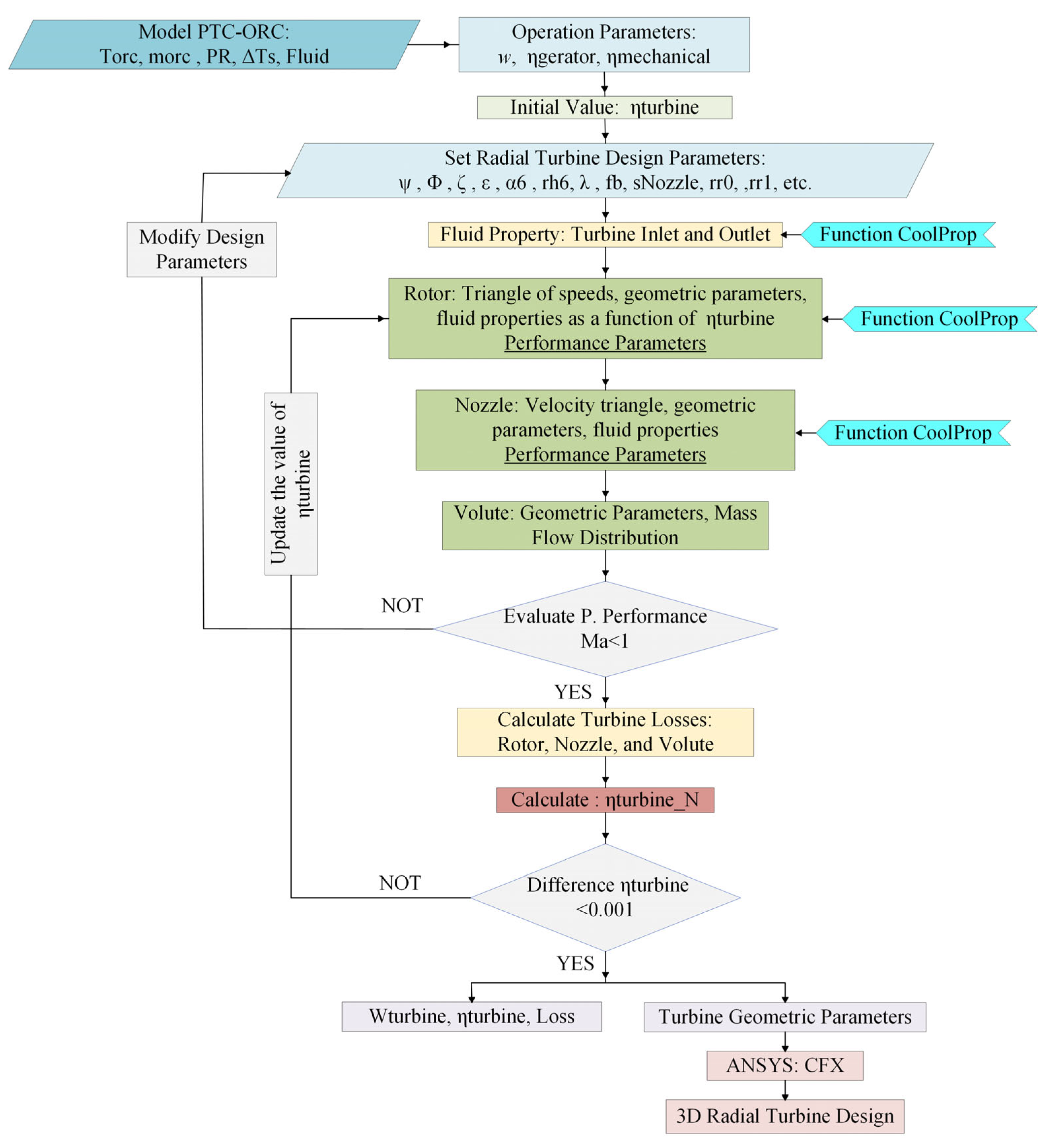
Figure 1. Calculation algorithm for a preliminary design of a radial inflow turbine.
Energies 16 03383 g001
Figure 2. Meridional view of the radial inflow turbine, indicating different components and main dimensions, adapted from [41].
Energies 16 03383 g002
Figure 3. Velocity triangle at the rotor inlet of a radial turbine, adapted from [45].
Energies 16 03383 g003
Figure 4. Velocity triangle at the rotor outlet of a radial turbine, adapted from [44].
Energies 16 03383 g004
Figure 5. Simplified diagram of the nozzle adapted from [29].
Energies 16 03383 g005
Figure 6. Schematic representation of the radial turbine and the main geometric design parameters.
Energies 16 03383 g006
Figure 7. Flowchart of the 3D radial turbine project method.
Energies 16 03383 g007
Figure 8. Losses in radial turbines operating with different working fluids.
Energies 16 03383 g008
Figure 9. Pressure boundaries in the meridional plane of the radial turbine nozzle-rotor set.
Energies 16 03383 g009
Figure 10. Distribution of the Mach number in the nozzle-rotor at 50% meridional plane height.
Energies 16 03383 g010
Figure 11. Distribution of the Mach number in the meridional plane of the nozzle-rotor set.
Energies 16 03383 g011
Figure 12. Distribution of the absolute velocity in the nozzle-rotor set at 50% blade height.
Energies 16 03383 g012
Figure 13. Variation in the total isentropic efficiency and power of the turbine operating with R-245fa, as a function of pressure ratio.
Energies 16 03383 g013
Figure 14. Variation in the total isentropic efficiency and power of the turbine operating with R-245fa, as a function of rotation speed.
Energies 16 03383 g014
Figure 15. Variation in the total isentropic efficiency and power of the turbine operating with R-141b, as a function of pressure ratio.
Energies 16 03383 g015
Figure 16. Variation in the total isentropic efficiency and power of the turbine operating with R-141b, as a function of rotation speed.
Energies 16 03383 g016
Figure 17. Variation in the total isentropic efficiency and power of the turbine operating with R-123, as a function of pressure ratio.
Energies 16 03383 g017
Figure 18. Variation in the total isentropic efficiency and power of the turbine operating with R-123, as a function of rotation speed.
Energies 16 03383 g018
Table 1. Input parameters of the radial turbine design.
Radial Turbine Parameters
FluidR-245fa
Flow coefficient (ϕ)0.215
Pressure coefficient (ψ)0.918
Inlet total pressure (kPa)1000
Condenser working temperature (K)303.15
Rotation (rpm)9000
Mass flow rate (kg/s)10.92
Table 2. Parameters compared in the validation of the radial turbine.
ParameterPaltrinieri [52]NEST ModelDifference (%)
Rotor
Inlet radius, r4 (m)0.17960.17094.8
Inlet blade height, b4 (m)0.01140.01067.0
Inlet absolute flow angle, α4 (°)76.818676.81860
Inlet relative flow angle, β4 (°)−43.4682−42.54842.1
Inlet static temperature, T4 (K)354.62353.78320.24
Inlet static pressure, p4 (kPa)585.37590.76880.92
Inlet absolute Mach number, Ma4 1.03691.04791.06
Inlet relative Mach number, Ma4′ 0.32580.278814.4
Outlet hub radius, r6h (m)0.05390.0531.7
Outlet shroud radius, r6s (m)0.11690.11821.1
Outlet blade height, b6 (m)0.0630.06533.7
Outlet absolute flow angle, α6 (°)−0.4018−0.40180
Outlet relative flow angle, β6_rms −64.0532−65.09621.6
Outlet static temperature, T6 (K)325.74323.80170.59
Outlet static pressure, p6 (kPa)171.81175.121.92
Outlet absolute Mach number, Ma6 0.25820.24345.7
Outlet relative Mach number, Ma6´ 0.590.62774.7
Number of blades, ZR (−)*18
Nozzle
Inlet radius, r1 (m)0.23350.22224.8
Inlet blade height, b1 (m)0.01140.01067.0
Inlet static temperature, T1 (K)369.75369.890.04
Inlet static pressure, p1 (kPa)995.88999.90.4
Inlet absolute Mach number, Ma10.0950.110015.7
Outlet radius, r2 (m)0.18110.17344.3
Outlet blade height, b2 (m)0.01140.01064.38
Outlet absolute flow angle, α2 (°)76.818676.81864.14
Inlet static temperature, T2 (K)354.62353.78320.174
Outlet static pressure, p2 (kPa)585.37590.76880.107
Outlet absolute Mach number, Ma2 1.03691.04791.06
Number of blades, ZB (−)25250
Total to static efficiency, ηts (%)74.171.853.0
Net Power, P (kW)267260.52.4
* The reference does not provide the value of the parameter.
Table 3. Parameters of the radial turbine project.
Parameter/FluidR-245faR-141bR-123b
Turbine nozzle inlet total temperature (°C)79.994.396.6
Mass flow rate of the working fluid (kg/s)0.610.450.62
Flow coefficient (ϕ)0.2150.2150.215
Load coefficient (ψ)0.9180.9180.918
Pressure ratio5.714.714.71
Rotation speed, ω (rpm)25,80022,00024,000
Table 4. Radial turbine nozzle and rotor parameters.
ParameterR-245faR-141bR-123
Rotor
Inlet radius, r4 (m)0.05680.05920.0531
Inlet blade height, b4 (m)0.00360.00390.0041
Inlet absolute flow angle, α4 (°)76.818676.818676.8186
Inlet relative flow angle, β4 (°)−45.718−46.0327−40.3337
Inlet static temperature, T4 (°C)66.580.381.5
Inlet static pressure, p4 (kPa)394.8306325.7557371.049
Inlet absolute Mach number, Ma40.95910.87980.9586
Inlet relative Mach number, Ma40.26180.23920.2541
Outlet hub radius, r6h (m)0.02220.02310.0207
Outlet shroud radius, r6s (m)0.0370.03760.0357
Outlet blade height, b6 (m)0.01480.01450.015
Outlet absolute flow angle, α6 (°)000
Outlet relative flow angle, β6_rms (°)−66.8922−66.6462−67.2171
Outlet relative flow angle, β6_h (°)−61.1328−61.1328−61.1328
Outlet relative flow angle, β6_t (°)−71.7233−71.3152−72.2554
Outlet static temperature, T6 (°C)37.547.453.5
Outlet static pressure, p6 (kPa)116.4663107.3252131.6736
Outlet absolute Mach number, Ma60.23570.22190.2299
Outlet relative Mach number, Ma60.59670.56170.5819
Number of blades, ZR (−)181818
Nozzle
Inlet radius, r1 (m)0.07390.07690.0691
Inlet blade height, b1 (m)0.00360.00390.0041
Inlet static temperature, T1 (°C)79.994.496.7
Inlet static pressure, p1 (kPa)659.1412505.5017620.1825
Inlet absolute Mach number, Ma1 0.19550.17960.1891
Inlet absolute flow angle, α1 (°)49.195849.319449.4424
Outlet radius, r2 (m)0.05750.05990.0539
Outlet blade height, b2 (m)0.00260.00390.0041
Outlet absolute flow angle, α2 (°)76.818676.818676.8186
Outlet static temperature, T2 (°C)66.580.381.5
Outlet static pressure, p2 (kPa)394.8306325.7557371.049
Outlet absolute Mach number, Ma20.95910.87980.9586
Blade thickness (mm)0.591710.589820.57152
Number of blades, ZB (−)252525
Table 5. Results of the mesh independent studies.
Working FluidNumber of
Elements
η t (%) P t (kW) Difference   ( % )   η t Difference   ( % )   P t
R-245fa413,84576.128.76--
629,39176.738.710.80.57
R-141b510,33080.309.41--
782,50680.479.370.210.42
R-123418,27677.607.37--
627,41478.207.400.770.40
Disclaimer/Publisher’s Note: The statements, opinions and data contained in all publications are solely those of the individual author(s) and contributor(s) and not of MDPI and/or the editor(s). MDPI and/or the editor(s) disclaim responsibility for any injury to people or property resulting from any ideas, methods, instructions or products referred to in the content.