


A Comprehensive Control Strategy for a Push–Pull Microinverter Connected to the Grid †


Abstract
:1. Introduction
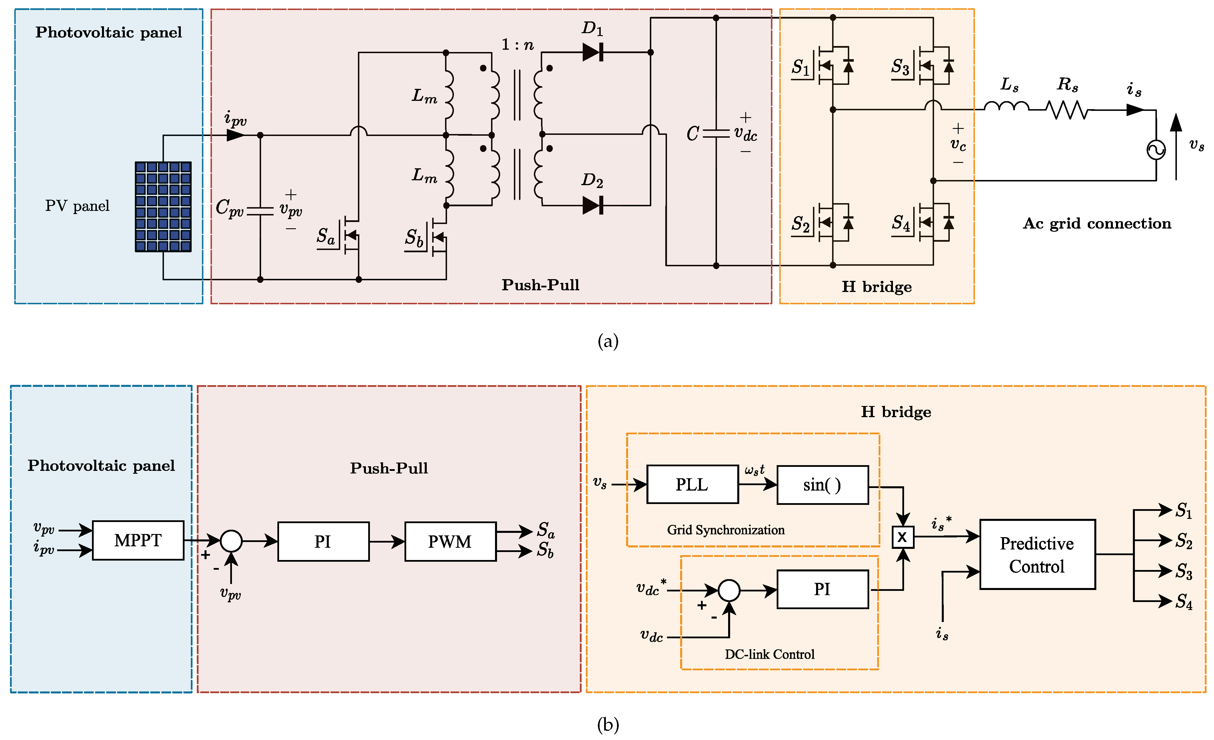
2. Overall System Model
- = DC-link voltage.
- = PV panel voltage.
- = number of secondary turns.
- = number of primary turns.
- = switching frequency (Hz).
- = time period of conduction (seconds).
- = time period of conduction (seconds).
3. Power Converters Controllers
3.1. Push–Pull Control
3.2. H-Bridge Control
- = predicted AC H-Bridge current a next step.
- = AC H-Bridge current.
- = sampling time.
- = AC H-Bridge inductance.
- = AC H-Bridge resistor.
- = AC H-Bridge voltage.
- = grid voltage.
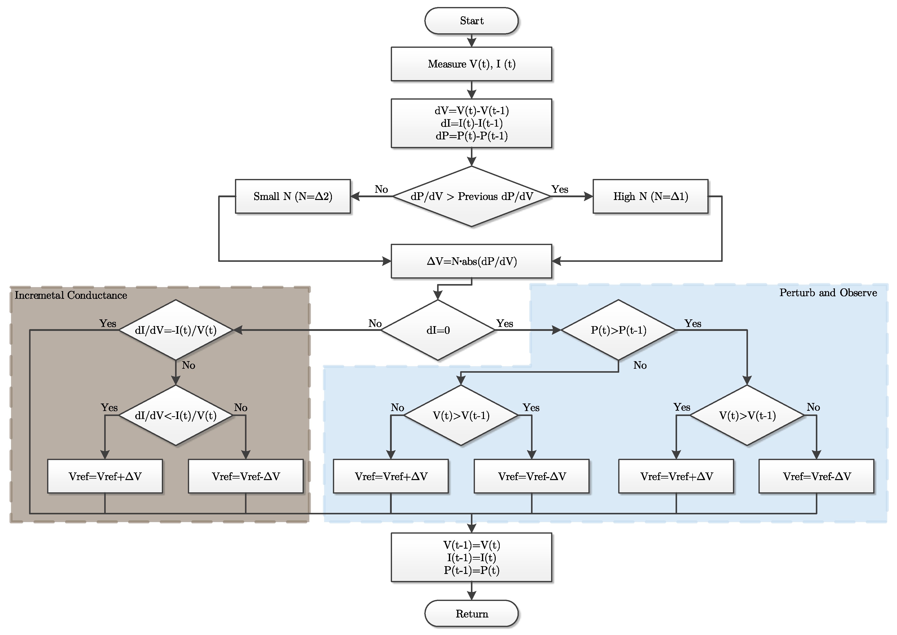
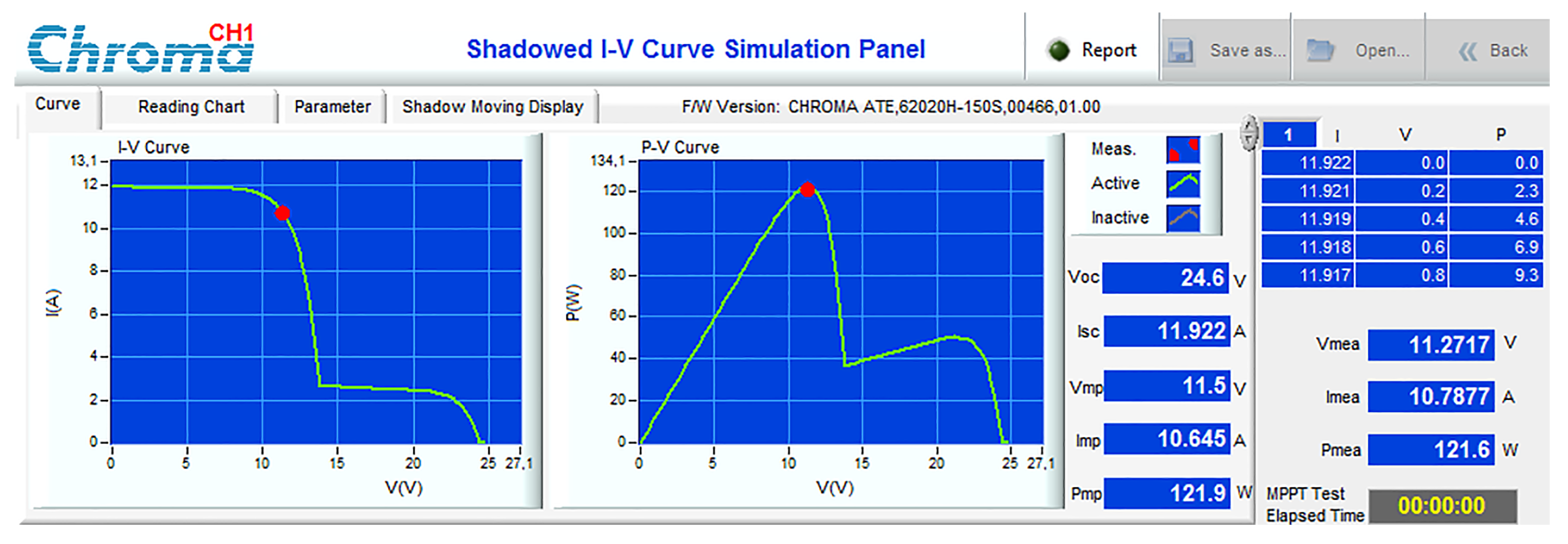
4. MPPT Algorithm
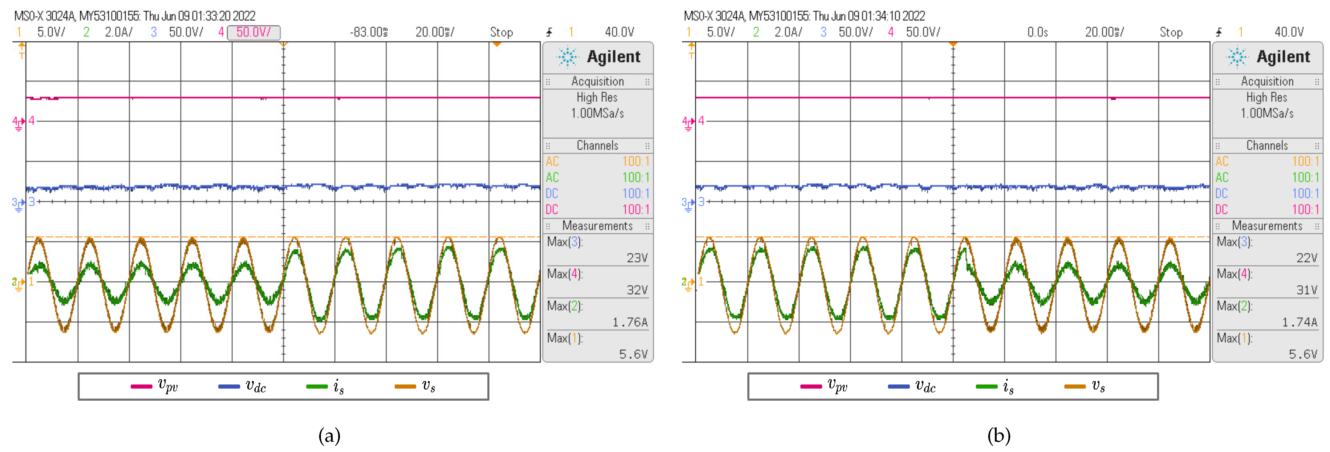
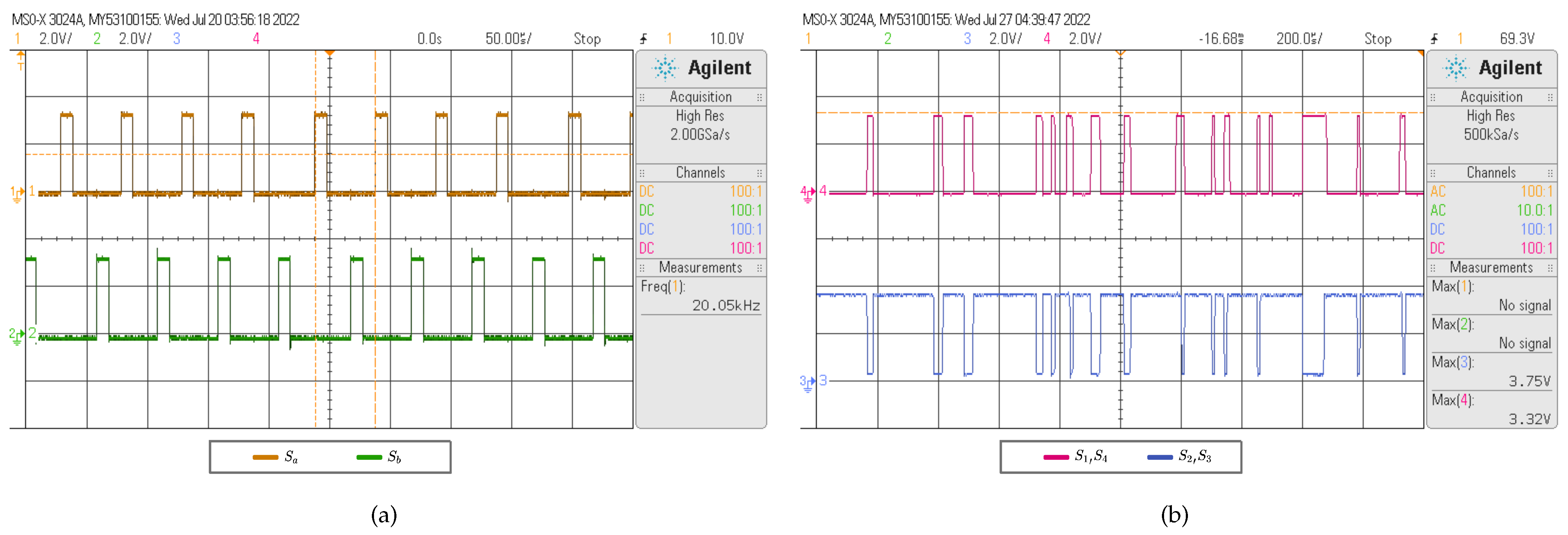
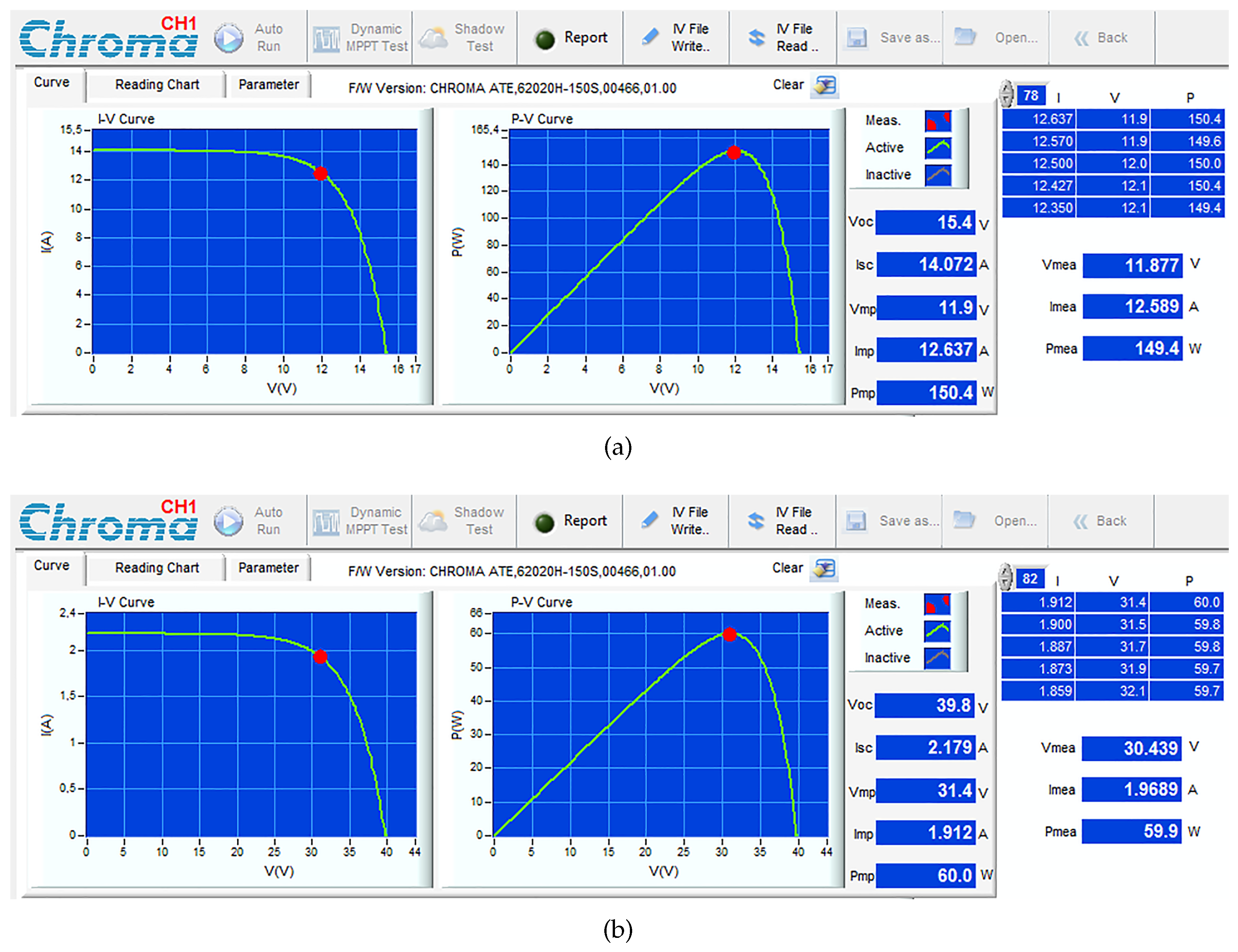
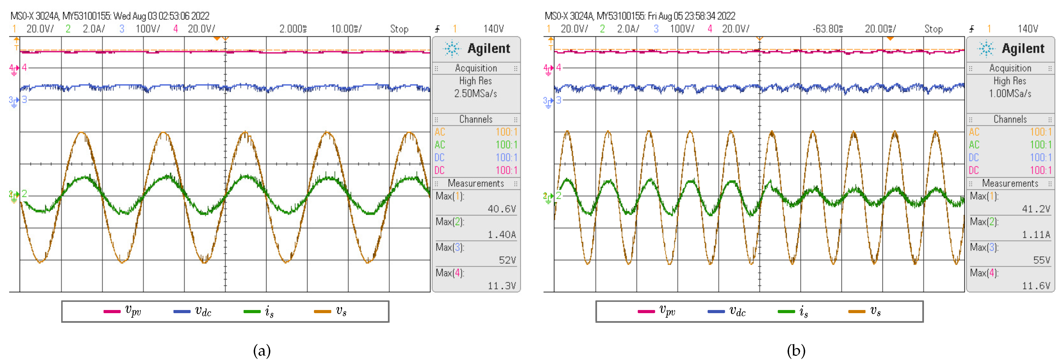
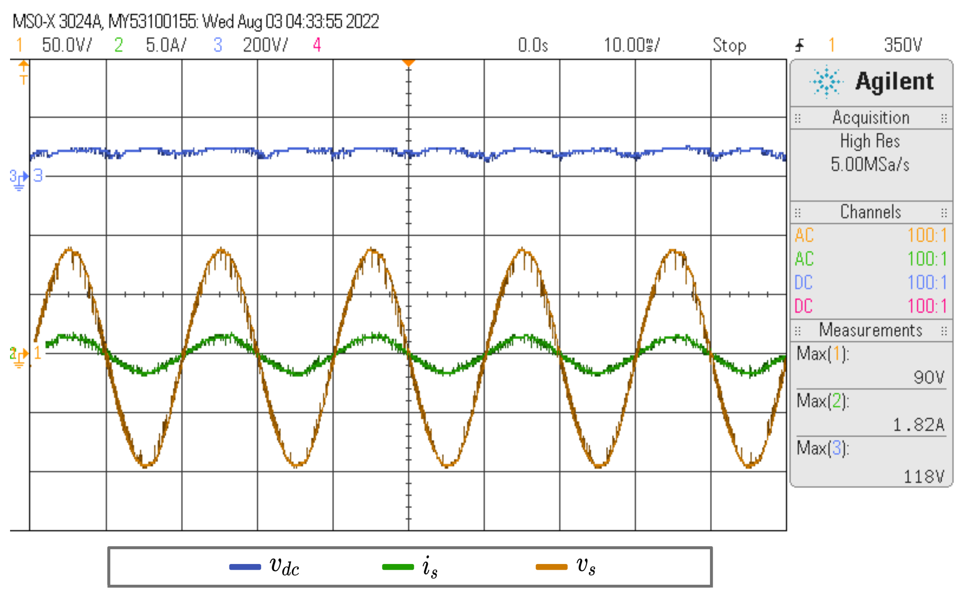
5. Results
- Chroma 62020H-150S programmable power supply.
- Photovoltaic panel model type A-255 GS (Atersa). The electrical ratings are:
- −
- Maximum Power Wp.
- −
- Open Circuit Voltage V.
- −
- Short Circuit Current A.
- −
- Maximum Power Voltage V.
- −
- Maximum Power Current A.
- Optical fiber receptor to command power switches, allowing fast communication and EMI/RFI immunity, among others.
- FPGA Basys3 (for generated the dead times in the power switches).
- TMS320F28335 Digital Signal Controllers.
- 1: Power supply (for instrumentation).
- 2: AC current sensors.
- 3: DC voltage sensors.
- 4: Push–pull converter.
- 5: Trigger card.
- 6: FPGA Basys3.
- 7: DSP TMS320F28335.
- 8: AC voltage sensor.
- 9: H bridge inverter.
6. Discussion
7. Conclusions
Author Contributions
Funding
Data Availability Statement
Conflicts of Interest
Abbreviations
| MPPT | Maximum Power Point Tracking |
| MPP | Maximum Power Point |
| GMPP | Global Maximum Power Point |
| LMPP | Local Maximum Power Point |
| P&O | Perturb and Observe |
| IC | Incremental Conductance |
References
- Shafiullah, M.; Ahmed, S.D.; Al-Sulaiman, F.A. Grid Integration Challenges and Solution Strategies for Solar PV Systems: A Review. IEEE Access 2022, 10, 52233–52257. [Google Scholar] [CrossRef]
- Tang, Z.; Yang, Y.; Blaabjerg, F. Power electronics: The enabling technology for renewable energy integration. CSEE J. Power Energy Syst. 2022, 8, 39–52. [Google Scholar]
- Sutikno, T.; Arsadiando, W.; Wangsupphaphol, A.; Yudhana, A.; Facta, M. A Review of Recent Advances on Hybrid Energy Storage System for Solar Photovoltaics Power Generation. IEEE Access 2022, 10, 42346–42364. [Google Scholar] [CrossRef]
- Kouro, S.; Leon, J.I.; Vinnikov, D.; Franquelo, L.G. Grid-Connected Photovoltaic Systems: An Overview of Recent Research and Emerging PV Converter Technology. IEEE Ind. Electron. Mag. 2015, 9, 47–61. [Google Scholar] [CrossRef]
- Karanayil, B.; Ceballos, S.; Pou, J. Maximum Power Point Controller for Large-Scale Photovoltaic Power Plants Using Central Inverters Under Partial Shading Conditions. IEEE Trans. Power Electron. 2019, 34, 3098–3109. [Google Scholar] [CrossRef]
- Pendem, S.R.; Mikkili, S. Assessment of cross-coupling effects in PV string-integrated-converters with P&O MPPT algorithm under various partial shading patterns. CSEE J. Power Energy Syst. 2020, 8, 1013–1028. [Google Scholar]
- Surirey, Q.; Hernandez-Vidal, R.; Renaudineau, H.; Kouro, S.; Cabon, B. Sub-module photovoltaic microinverter with cascaded push-pull and unfolding H-bridge inverter. In Proceedings of the IEEE Southern Power Electronics Conference (SPEC), Puerto Varas, Chile, 4–7 December 2017; pp. 1–6. [Google Scholar]
- Alluhaybi, K.; Batarseh, I.; Hu, H. Comprehensive Review and Comparison of Single-Phase Grid-Tied Photovoltaic Microinverters. IEEE J. Emerg. Sel. Top. Power Electron. 2020, 8, 1310–1329. [Google Scholar] [CrossRef]
- Krein, P.T.; Galtieri, J.A. Active Management of Photovoltaic System Variability With Power Electronics. IEEE J. Emerg. Sel. Top. Power Electron. 2021, 9, 6507–6523. [Google Scholar] [CrossRef]
- Sher, H.A.; Addoweesh, K.E.; Al-Haddad, K. An Efficient and Cost-Effective Hybrid MPPT Method for a Photovoltaic Flyback Microinverter. IEEE Trans. Sustain. Energy 2018, 9, 1137–1144. [Google Scholar] [CrossRef]
- Diaz-Bernabe, J.L.; Morales-Acevedo, A. Simulation of a double-stage micro-inverter for grid-connected photovoltaic modules. In Proceedings of the International Conference on Electrical Engineering, Computing Science and Automatic Control (CCE), Mexico City, Mexico, 26–30 September 2016; pp. 1–6. [Google Scholar]
- de Oliveira Lima, R.; Barreto, L.H.S.C.; Reis, F.E.U. Hybrid MPPT Control Applied to a Flyback Micro-Inverter Connected the Electrical Grid. In Proceedings of the IEEE International Conference on Industry Applications (INDUSCON), Sao Paulo, Brazil, 12–14 November 2018; pp. 59–64. [Google Scholar]
- Bollipo, R.B.; Mikkili, S.; Bonthagorla, P.K. Hybrid, optimal, intelligent and classical PV MPPT techniques: A review. CSEE J. Power Energy Syst. 2021, 7, 9–33. [Google Scholar]
- Zhou, L.; Chen, Y.; Guo, K.; Jia, F. New Approach for MPPT Control of Photovoltaic System With Mutative-Scale Dual-Carrier Chaotic Search. IEEE Trans. Power Electron. 2011, 26, 1038–1048. [Google Scholar] [CrossRef]
- Lyden, S.; Haque, M.E. A Simulated Annealing Global Maximum Power Point Tracking Approach for PV Modules Under Partial Shading Conditions. IEEE Trans. Power Electron. 2016, 31, 4171–4181. [Google Scholar] [CrossRef]
- González-Castaño, C.; Restrepo, C.; Kouro, S.; Rodriguez, J. MPPT Algorithm Based on Artificial Bee Colony for PV System. IEEE Access 2021, 9, 43121–43133. [Google Scholar] [CrossRef]
- Díaz, M.; Muñoz, J.; Rivera, M.; Aliaga, R.; Rohten, J. Hybrid MPPT Control Applied to a Push-Pull based pseudo DC-link PV microinverter. In Proceedings of the European Conference on Power Electronics and Applications (EPE’21 ECCE Europe), Ghent, Belgium, 6–10 September 2021; pp. 1–7. [Google Scholar]
- Carandell, M.; Holmes, A.S.; Toma, D.M.; del Río, J.; Gasulla, M. Effect of the Sampling Parameters in FOCV-MPPT Circuits for Fast-Varying EH Sources. IEEE Trans. Power Electron. 2023, 38, 2695–2708. [Google Scholar] [CrossRef]
- Sher, H.A.; Murtaza, A.F.; Noman, A.; Addoweesh, K.E.; Al-Haddad, K.; Chiaberge, M. A New Sensorless Hybrid MPPT Algorithm Based on Fractional Short-Circuit Current Measurement and P&O MPPT. IEEE Trans. Sustain. Energy 2015, 6, 1426–1434. [Google Scholar]
- Morales, R.H.; Rohten, J.A.; Garbarino, M.N.; Muñoz, J.A.; Silva, J.J.; Pulido, E.S.; Espinoza, J.R.; Andreu, M.L. A Novel Global Maximum Power Point Tracking Method Based on Measurement Cells. IEEE Access 2022, 10, 2169–3536. [Google Scholar]
- Melo, F.C.; Garcia, L.S.; de Freitas, L.C.; Coelho, E.A.A.; Farias, V.J.; de Freitas, L.C.G. Proposal of a Photovoltaic AC-Module With a Single-Stage Transformerless Grid-Connected Boost Microinverter. IEEE Trans. Ind. Electron. 2018, 65, 2289–2301. [Google Scholar]
- Noge, Y.; Yamaguchi, M.; Miyashita, M.; Deng, M. Experimental verification of buck-boost converter based micro inverter for minimization of magnetic components. In Proceedings of the International Conference on Electrical Machines and Systems (ICEMS), Sydney, Australia, 11–14 August 2017; pp. 1–5. [Google Scholar]
- Hasan, R.; Hassan, W.; Xiao, W. PV Microinverter Solution for High Voltage Gain and Soft Switching. IEEE J. Emerg. Sel. Top. Ind. Electron. 2022, 3, 352–361. [Google Scholar] [CrossRef]
- Zhang, F.; Xie, Y.; Hu, Y.; Chen, G.; Wang, X. A Hybrid Boost–Flyback/Flyback Microinverter for Photovoltaic Applications. IEEE Trans. Ind. Electron. 2022, 67, 308–318. [Google Scholar] [CrossRef]
- Rajeev, M.; Agarwal, V. Analysis and Control of a Novel Transformer-Less Microinverter for PV-Grid Interface. IEEE J. Photovoltaics 2018, 8, 1110–1118. [Google Scholar] [CrossRef]
- Hernandez-Vidal, R.; Surirey, Q.; Renaudineau, H.; Kouro, S.; Cabon, B. Push-pull based pseudo DC-link PV microinverter. In Proceedings of the Annual Conference of the IEEE Industrial Electronics Society, Beijing, China, 29 October–1 November 2017; pp. 7843–7848. [Google Scholar]
- Tseng, K.-C.; Li, I.-C.; Cheng, C.-A. Integrated Buck and Modified Push-Pull DC-DC Converter With High Step-Down Ratio. IEEE Trans. Ind. Electron. 2020, 67, 235–243. [Google Scholar] [CrossRef]
- Palma, L. Single Stage Quasi-Z-Source Push-Pull based Microinverter for On-Grid PV Applications. In Proceedings of the International Conference on Clean Electrical Power (ICCEP), Otranto, Italy, 2–4 July 2019; pp. 433–437. [Google Scholar]
- Muñoz, J.; Díaz, M.; Rivera, M.; Dekka, A. Push-Pull Microinverter based on a Sub-modular Structure. In Proceedings of the International Symposium on Power Electronics, Electrical Drives, Automation and Motion (SPEEDAM), Sorrento, Italy, 22–24 June 2022; pp. 883–888. [Google Scholar]
- Wu, Q.; Wang, Q.; Xu, J.; Li, H.; Xiao, L. A High-Efficiency Step-Up Current-Fed Push–Pull Quasi-Resonant Converter with Fewer Components for Fuel Cell Application. IEEE Trans. Ind. Electron. 2017, 64, 6639–6648. [Google Scholar] [CrossRef]
- Mathew, D.; Naidu, R.C. Investigation of single-stage transformerless buck-boost microinverters. IET Power Electron. 2020, 8, 1487–1499. [Google Scholar] [CrossRef]
- Knabben, G.C.; Schmitz, L.; Coelho, R.F.; Cruz Martins, D.; Custódio, O.J.; de Medeiros, R.Z.; Bettiol, A.L. Transformerless micro-inverter for grid-connected photovoltaic systems. In Proceedings of the International Universities Power Engineering Conference (UPEC), Heraklion, Greece, 28–31 August 2017; pp. 1–6. [Google Scholar]
- Paul, A.R.; Bhattacharya, A.; Chatterjee, K. A Novel SEPIC-Ćuk Based High Gain Solar Micro-Inverter for Integration to Grid. In Proceedings of the National Power Electronics Conference (NPEC), Tiruchirappalli, India, 13–15 December 2019; pp. 1–5. [Google Scholar]
- Bhattacharya, A.; Paul, A.R.; Chatterjee, K. A Single Phase Single Stage SEPIC-ĆUK Based Non-Isolated High Gain and Efficient Micro-Inverter. In Proceedings of the IEEE 46th Photovoltaic Specialists Conference (PVSC), Chicago, IL, USA, 16–21 June 2019; pp. 0708–0715. [Google Scholar]
- Dong, D.; Agamy, S.; Harfman-Todorovic, M.; Liu, X.; Garces, L.; Zhou, R.; Cioffi, P. A PV Residential Microinverter With Grid-Support Function: Design, Implementation, and Field Testing. IEEE Trans. Ind. Appl. 2018, 54, 469–481. [Google Scholar] [CrossRef]
- Wu, D.; Wu, Y.; Kan, J.; Tang, Y.; Chen, J.; Jiang, L. Full-Bridge Current-Fed PV Microinverter With DLFCR Reduction Ability. IEEE Trans. Power Electron. 2020, 35, 9541–9552. [Google Scholar] [CrossRef]
- Tayebi, S.M.; Batarseh, I. Mitigation of Current Distortion in a Three-Phase Microinverter With Phase Skipping Using a Synchronous Sampling DC-Link Voltage Control. IEEE Trans. Ind. Electron. 2018, 65, 3910–3920. [Google Scholar] [CrossRef]


| State | |||||
|---|---|---|---|---|---|
| 1 | 0 | 1 | 0 | 1 | 0 |
| 2 | 0 | 1 | 1 | 0 | |
| 3 | 1 | 0 | 0 | 1 | |
| 4 | 1 | 0 | 1 | 0 | 0 |
| Algorithm MPPT | Efficiency | Tracking Speed | Presents Optimization Function | Perturbations in the Operating Point (Voltage) | Implementation Complexity |
|---|---|---|---|---|---|
| Chaotic Search | High | High | Yes | Yes | High |
| ABC | High | High | No | Yes | Medium |
| Simulated Annealing | High | High | Yes | Yes | High |
| Hybrid MPPT (this work) | High | High | No | Yes | Medium |
| Component | Description |
|---|---|
| Power switches , , , , and | CREE C2M0080120 |
| Rectifier diode , | RURG80100 |
| High frequency transformer | ETD-49 |
| Electrolytic capacitor C | 10 mF 50 V |
| Electrolytic capacitor | 100 uF 450 V |
Disclaimer/Publisher’s Note: The statements, opinions and data contained in all publications are solely those of the individual author(s) and contributor(s) and not of MDPI and/or the editor(s). MDPI and/or the editor(s) disclaim responsibility for any injury to people or property resulting from any ideas, methods, instructions or products referred to in the content. |
© 2023 by the authors. Licensee MDPI, Basel, Switzerland. This article is an open access article distributed under the terms and conditions of the Creative Commons Attribution (CC BY) license (https://creativecommons.org/licenses/by/4.0/).
Share and Cite
Díaz, M.; Muñoz, J.; Rivera, M.; Rohten, J. A Comprehensive Control Strategy for a Push–Pull Microinverter Connected to the Grid. Energies 2023, 16, 3196. https://doi.org/10.3390/en16073196
Díaz M, Muñoz J, Rivera M, Rohten J. A Comprehensive Control Strategy for a Push–Pull Microinverter Connected to the Grid. Energies. 2023; 16(7):3196. https://doi.org/10.3390/en16073196
Chicago/Turabian StyleDíaz, Manuel, Javier Muñoz, Marco Rivera, and Jaime Rohten. 2023. "A Comprehensive Control Strategy for a Push–Pull Microinverter Connected to the Grid" Energies 16, no. 7: 3196. https://doi.org/10.3390/en16073196
APA StyleDíaz, M., Muñoz, J., Rivera, M., & Rohten, J. (2023). A Comprehensive Control Strategy for a Push–Pull Microinverter Connected to the Grid. Energies, 16(7), 3196. https://doi.org/10.3390/en16073196