1. Introduction and Motivation
Efficient plasma heating is one of the main challenges of nuclear fusion. Different methods are used to bring the plasma temperature to the desired level, with the neutral beam injector (NBI) as the most powerful one [
1]. An NBI introduces a particle beam of energetic deuterium atoms into the plasma chamber. Consequently, the system consists of a beam source generating the needed number of negative ions, the acceleration of these ions with electrical fields and the re-neutralization of these particles, which can then be injected in the magnetically confined fusion plasma. For a proper operation of such an injector, an extremely powerful vacuum pumping system is needed in order to limit the pressure to an acceptable level for the beam operation inside the NBI vessel, on the one hand, and to manage the large gas flows which result mainly from the re-neutralization unit, on the other hand. On top of this, a specific pressure profile along the inner beam line of an NBI has to be achieved and maintained. This demanding requirement (e.g., at an ITER with <25 mPa maximum pressure under a gas load of >40 Pa·m
3/s) was feasible only with tailor-made in-situ cryopumps [
2,
3]. In the past, no other pumping technology was capable to achieve the needed pumping speed of several thousand m
3/s for hydrogen and for deuterium within an available area of ~45 m
2 within the inner wall surface of the NBI vessel.
In view of DEMO, the demonstration power plant succeeding ITER, additional aspects, including energy efficiency, have gained importance. Since cryopumps need a continuous He supply at 4 K and 80 K—even when no high gas throughput is required to be removed—the primary energy consumption of a cryopump is very high. With the occurrence of ZAO®, a new non-evaporable getter (NEG) material from SAES Getters, Lainate, Italy, and combining a high pumping speed for H2 with a much better mechanical robustness than traditional NEG materials, a new option has been created. The question was whether this technology could become an alternative option to cryopumps, working at relatively moderate pressures of 0.02 Pa which are atypical for getter pumping. An NEG pump needs to be coupled with an auxiliary pumping system for hydrogen extraction (during regeneration) and for absorbing noble gases (during pumping) which are—to some limited extent—present in the NBI application. However, while both concepts accumulate hydrogen, which has safety implications that need to be carefully managed, the difference is that a cryopump will release all of the sorbed gas in a loss-of-coolant event, while an NEG pump has the advantage of releasing the inventory only when being actively regenerated by heating.
With this potential benefit, a long term collaboration between KIT, Consorzio RFX and SAES Getters under the umbrella of EUROfusion began. In over 6 years, this development path has comprised all steps beginning with a systematic investigation of the NEG properties under conditions unusual for an NEG in an integrated approach at SAES, KIT and RFX [
4]. This approach also includes the investigations of relevant aspects implied by a large volume NEG arrangement, from the concept [
5] to the design. A general overview of the development is given in [
6].
The final step is the manufacturing and investigation of the resulting large pump, ready for scale-up and able to answer all questions for future NBI applications. This manuscript reports on the experimental campaign performed in the TIMO facility at KIT and all of the achieved results on the pumping, regenerating and operating of the developed pump. Subsequently, it presents the simulation activities aimed at extracting the capture coefficient of the cartridges from the experiments for future reference.
2. The Development of the NEG Pump
2.1. Stepwise NEG Arrangement Characterizations
Following the fundamental characterization of the ZAO
® material properties [
4], a stepwise approach was followed to investigate the different aspects in arrangements larger than one disk.
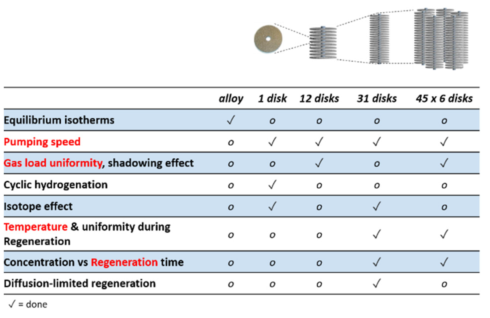
Figure 1 shows the aspects that have been addressed experimentally on different scales: with a smaller or larger stack of 12 or 31 disks, respectively, and with a cartridge of six stacks of 45 disks each. The ZAO
® disks have a diameter of 25 mm, a thickness of 2 mm and contain 3.5 g of getter material. The result of this approach was the capability to assume roughly the behavior of a large pump that could be manufactured and tested.
2.2. Arrangement Selection
The first design step for an NEG pump is to find an appropriate and advantageous arrangement that is potentially scalable for future applications. The configuration has to compromise performance against several operational aspects. A high packing density of getter material, for example, would promise a higher capacity due to a higher getter mass installed within the same area but not necessarily a higher pumping speed due to the blocked access of the disks for the gas. Furthermore, the promised capacity is not exploitable if a considerable fraction of disks is not reached by the gas. Consequently, several simulations were performed to study all of these dependencies of the three different arrangements [
7], as summarized in the following.
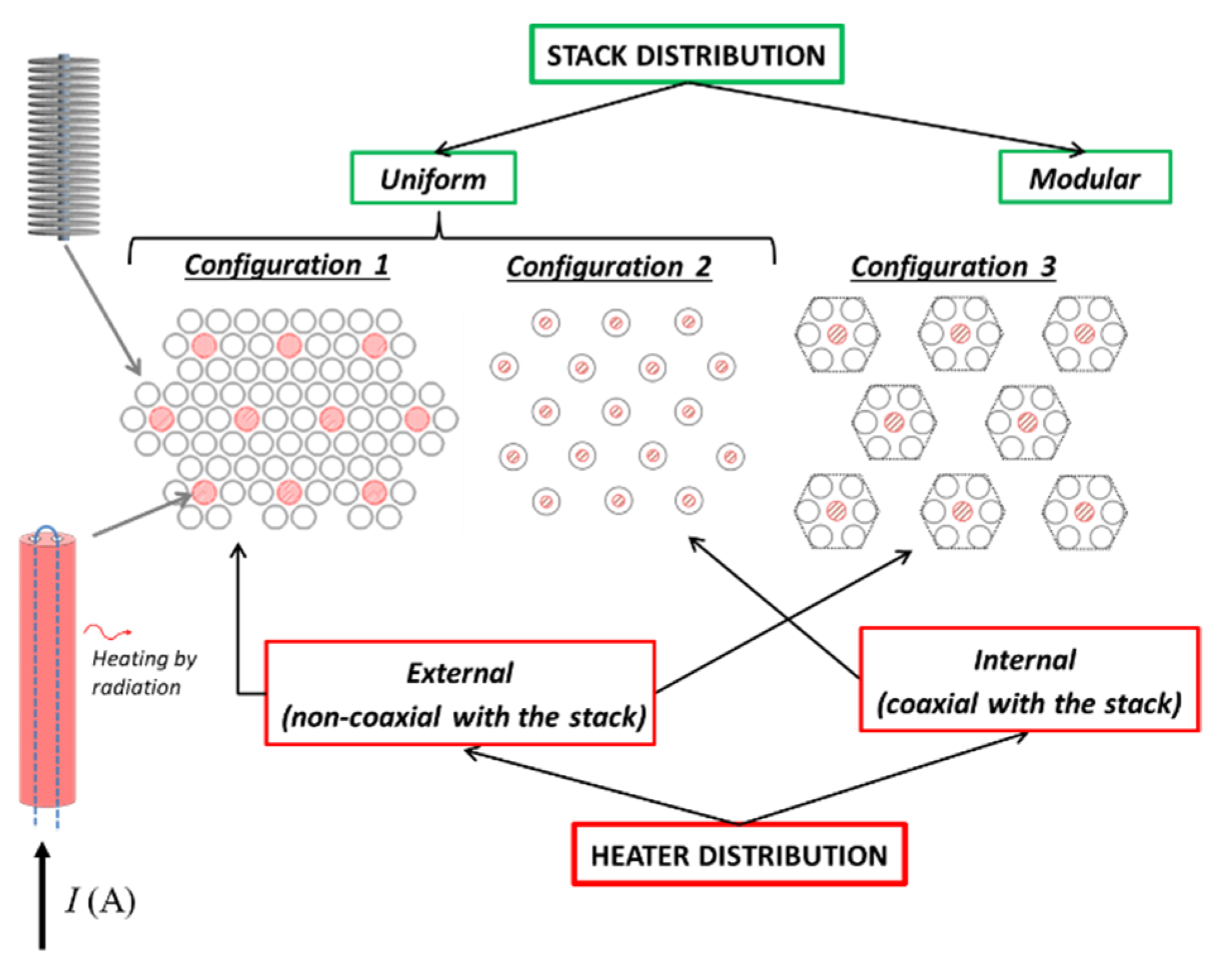
Figure 2 shows the general schemes investigated in advance, including the different heater solutions. The basic idea was to explore different approaches about getter stack distribution (dense, sparse or modular) and heater positions (coaxial with the stack or not). All three configurations were evaluated regarding gas load uniformity, as well as their temperature behavior during heating, regeneration and cooling. As an example,
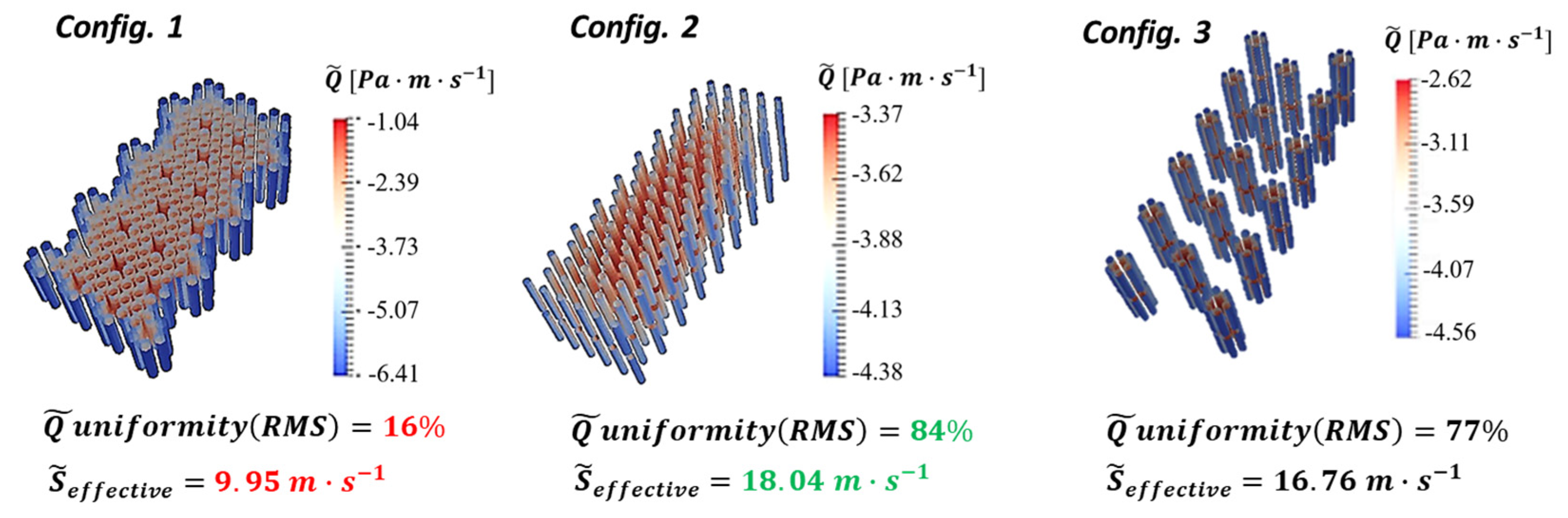
Figure 3 shows a simulation of the gas load distribution for hydrogen at 27 °C. Here,
is the throughput per unit area and shows different values at different positions. The statistical variations of
give a
uniformity. It is illustrated that configuration 1 is clearly worse in terms of gas load uniformity. This is also linked with a broader temperature distribution, in particular towards the external parts of the arrangement [
5]. The differences between configurations 2 and 3 are generally smaller. Although configuration 2 was found to perform slightly better in terms of gas load uniformity and pumping speed, the cooling behavior and particularly the capacity (twice the getter mass per unit area) were found to be better for configuration 3. Furthermore, configuration 3 resulted in a drastically reduced number of heater elements, cabling, feedthroughs and controllers. On top of this, the single units of configuration 3 were based to some extent on commercially available cartridges, which added advantages for scalability, modularity and reliability. This is why configuration 3 was finally chosen. The cartridge geometry was a result of an optimization study [
7] and therefore it was used as the smallest unit. Additional detailed tests and analyses were carried out on the cartridge, after it was selected as the basic module for the pump.
2.3. Manufactured Pump
Following the decision concerning the cartridge-based pump design, the detailed engineering and manufacturing began under the responsibility of SAES with the support of the computational engineering part of Consorzio RFX. The cartridge design is derived from the commercial one, with 45 disks on each stack and six stacks in a cartridge. Moreover, the heater elements are a special development by SAES for this task providing two redundant Ta filaments in each cartridge which can be switched in case of a failed one. This improvement was designed for an application with demanding requirements for a high reliability and low maintenance.
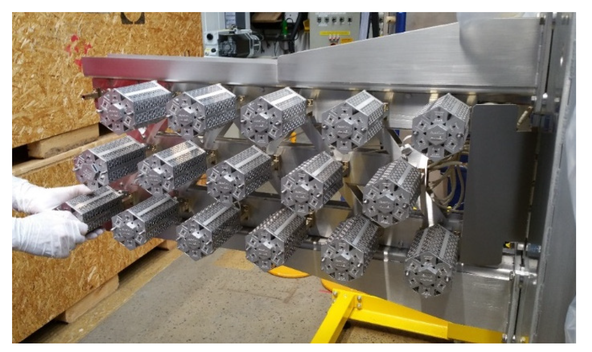
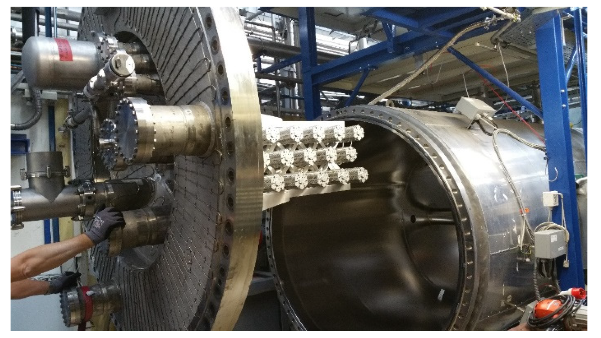
Figure 4 shows these cartridges at the fully assembled pump with 17 units in total and with a size of 1 m in length and 0.4 m in height. The decision for this size and the number of cartridges was based on the need for scalability. This means that the pump had to be manufactured large enough to be representative regarding the application. The size of 17 cartridges was herewith a balance between an extended pump arrangement, not only consisting of outer cartridges (on edges or corners), but limiting at the same time costs, the size for handling, the required heating power for regeneration and other aspects, such as regeneration, duration or hydrogen inventory in the test facility.
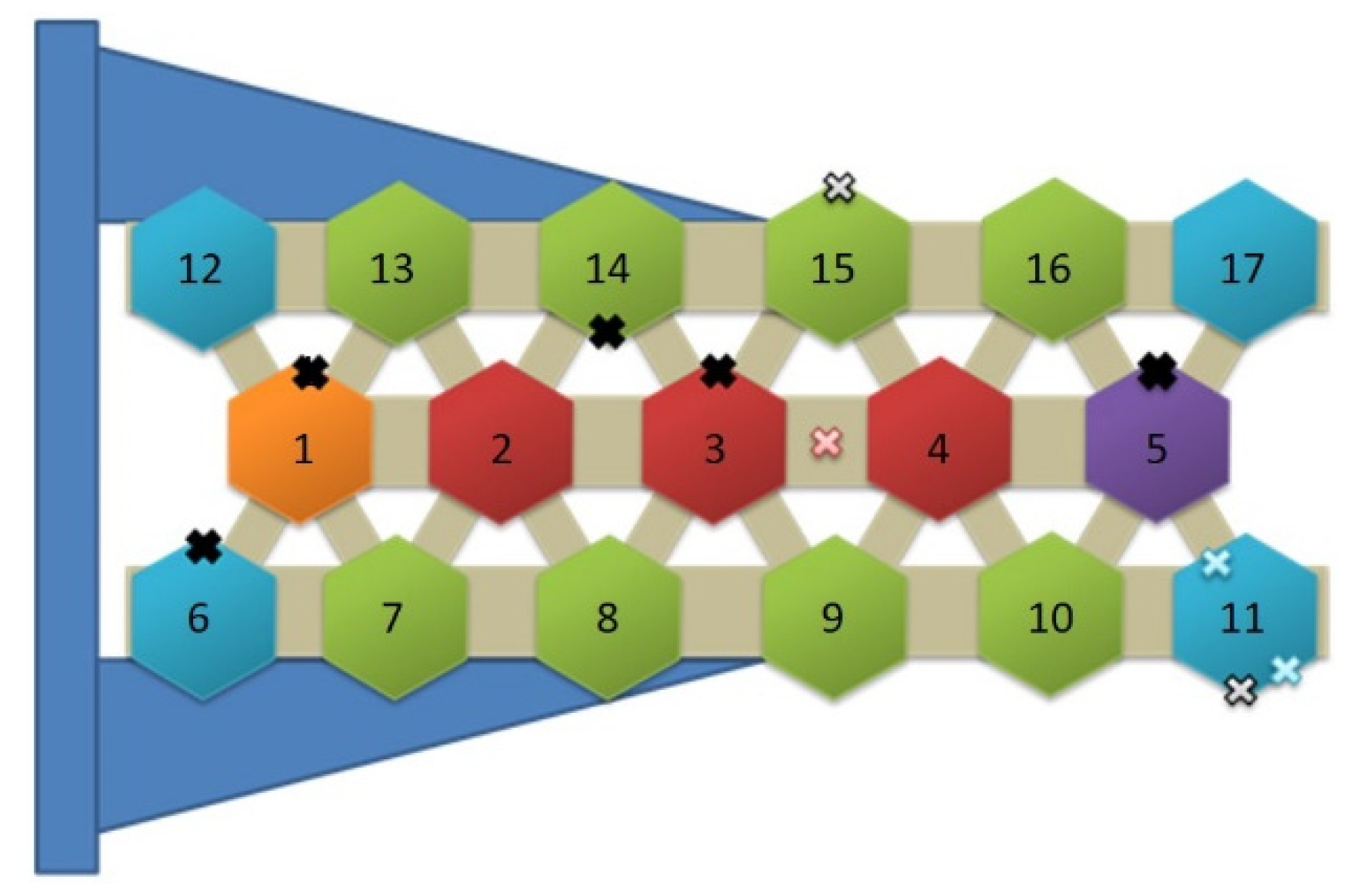
The cabling system in the pump utilizes only ceramic insulation to cope with temperatures above 400 °C during regeneration, that is measured in the cabling system. For temperature measurement, several thermocouples at different positions in the pump, representing outer and inner cartridges, the mounting structure or the cabling channel in the center have been installed. For temperature control during operation and especially during regeneration, the 17 cartridges have been grouped into five sections representing the different thermal conditions, e.g., the edge or the innermost part of the pump.
Figure 5 shows the resulting pattern. With a master-slave concept for each of the five sections, all of the cartridges of a section are operated with identical heating parameters determined by the measurement of the condition of their master. As a consequence, the system has to perform the control for five sections only, instead of 17 cartridges. This allows for the reduction of thermocouples and feedthroughs, the simplification of the control system and software and, most importantly, the potential development of a concept suitable for any scale-up to hundreds of cartridges.
3. The TIMO Facility
The TIMO (
test facility for the
ITER
model pump) facility at KIT was established more than 20 years ago for the testing of large cryogenic pumps for ITER [
8]. Today, it is still the perfect facility for the large testing of pump units requiring a significant amount of hydrogen throughput. It offers a 10 m
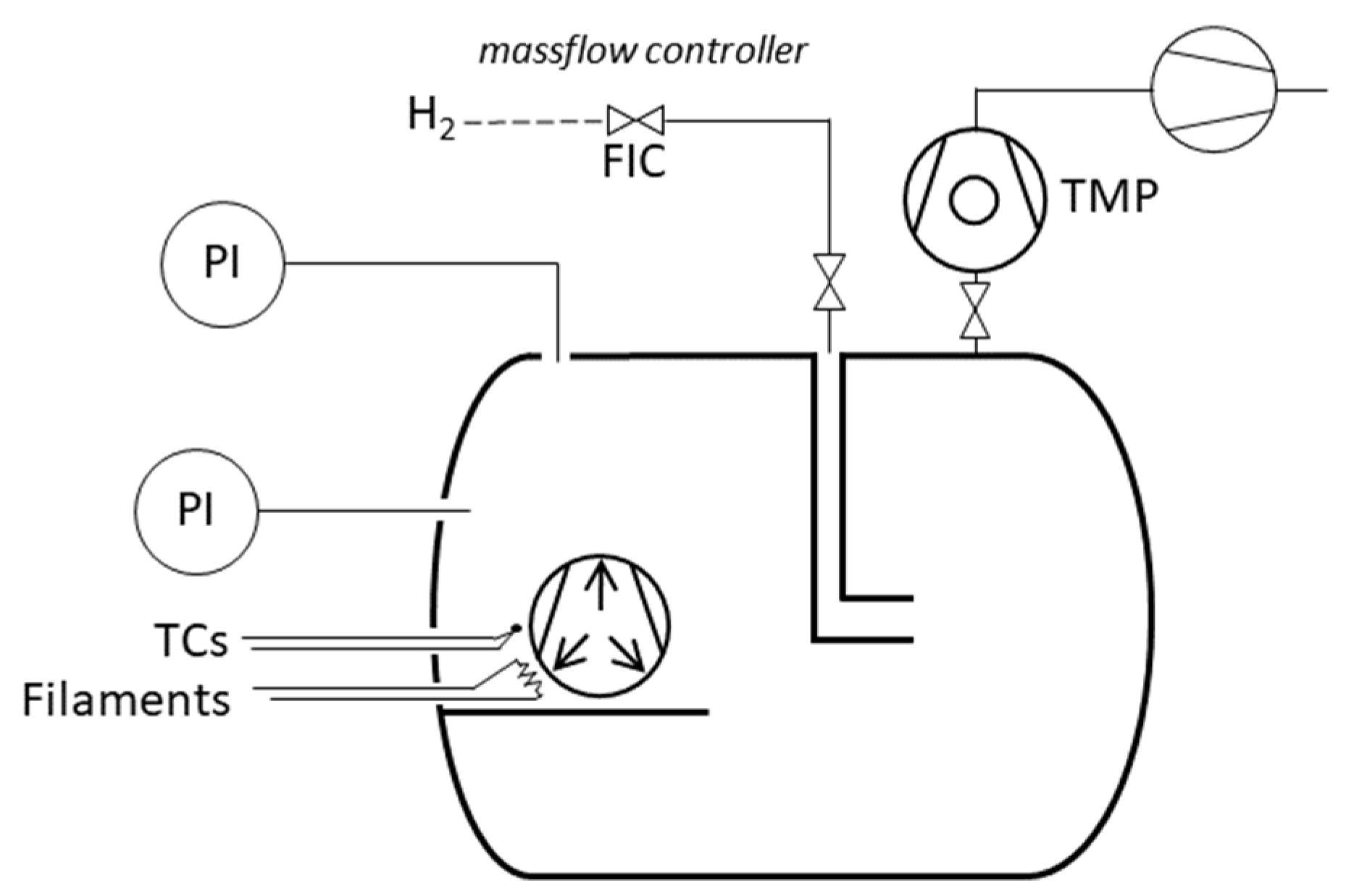
3 cylindrical vessel of ~1.7 m inner diameter and a hydrogen inventory certification up to 20 mol. A schematic diagram, showing the most important subsystems, is given in
Figure 6.
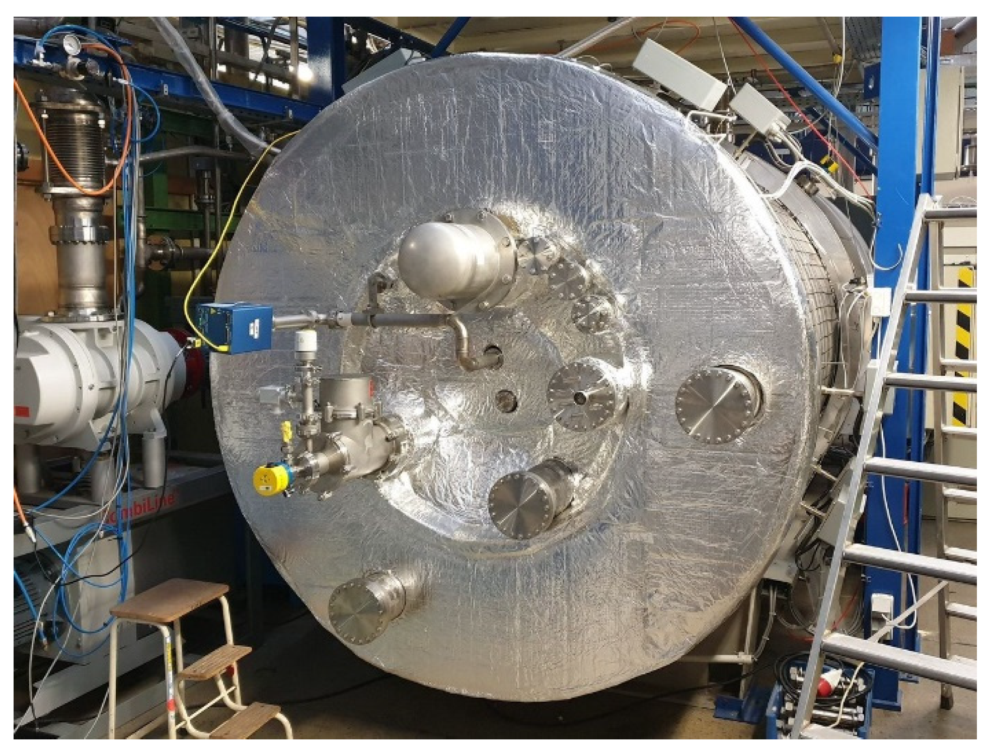
Figure 7 shows TIMO looking on its main flange after the installation of the NEG pump, but before the installation of all of the connections.
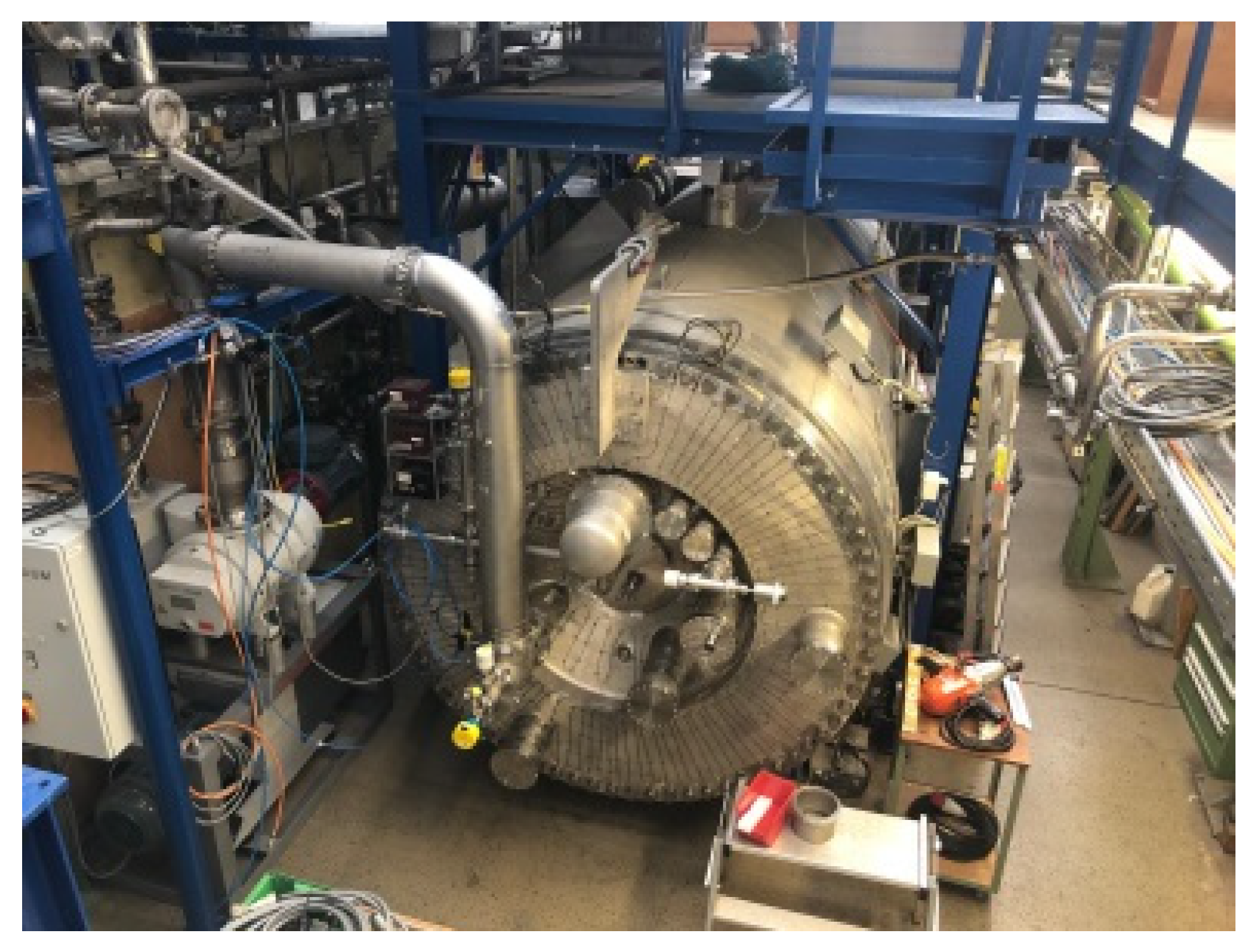
Figure 8 shows the bird’s eye view of the facility and
Figure 9 shows the open TIMO vessel during the NEG pump installation.
Several activities have been performed to modify the TIMO facility according to the special needs of the experimental campaign. The resulting details that are relevant for the experiments are described in the following. The new data acquisition system based on Delphin® was combined with an additional safety control for the hydrogen inventory in the getter. The heating and insulation systems of TIMO were adapted in view of the following two aspects. The first one is the capability to bake out the entire vessel after air exposure at 140 °C. The second is to find an appropriate balance between sufficient insulation to enable bake out with the limited given heating power and the need for reduced insulation for an appropriately short duration of the cool down after the NEG pump regeneration at 550 °C. The most significant change in the TIMO facility is on the vacuum pumping system. The pumping speed had to be increased as much as possible for a reduction in the NEG regeneration time. Since this effect is strong, the largest applicable turbo molecular pump (TMP) (Leybold MAG W 2200 iP) was installed providing a nominal pumping speed of 1.75 m3/s for hydrogen. The new roughing pump installed behind this upgraded TMP was a dry SCREWLINE Leybold 250 ATEX. The pressure measurement is guaranteed by the redundant cascade of four calibrated capacitance manometers (MKS Baratron), (from 105 Pa down to 10−3 Pa), with a reading pressure at two different positions in the TIMO vessel. This allows for the independent measurement of the gas species and the averaging of the two almost identical pressure values at these two positions. A temperature stabilized by the MKS mass flow controller (1000 sccm range) is used to supply the necessary calibrated gas throughout.
4. Procedure of Sorption and Regeneration
All of the experiments followed the constant mass flow approach. At the start of an experimental run, a mass flow is established and as soon as stable conditions have been achieved, the mass flow is injected into the TIMO vessel starting the sorption process. Now, the resulting pressure in the TIMO vessel during sorption of a certain mass flow can, also considering the contribution of the TMP, be translated into the current pumping speed of the NEG pump. The gas dosage runs until a desired accumulated inventory in the getter is achieved. Herewith, the mass flow is kept constant during the entire experimental duration, accepting that the pressure is slowly rising a bit due to the increasing inventory in the getter, and a resulting decrease in the pumping speed is observed. This constant mass flow method was chosen since it represents at best the operation conditions for a pump in an NBI, in spite of the fact that most of the literature about getters reports experiments at a constant pressure.
It is important to mention the presence of the TMP. Since the NEG does not pump noble gases and methane, during all experiments, the TMP was pumping in parallel with the NEG pump keeping the level of non-getterable gases in the vessel very low. It is clear that the effective pumping speed of the TMP for hydrogen—previously experimentally determined—was subtracted in the data processing during and after the experiments.
All of the experiments were performed using the 0.1 Torr Baratron units. The test gas, hydrogen (H2) of 6.0 quality was employed, except where stated otherwise.
Following each experimental run, the dosage of hydrogen was stopped at a desired achieved inventory in the getter. Therefore, the duration of an experiment resulted from the combination of gas flow (related to the aimed pressure during sorption) and the achieved inventory, and ranged from 4 to 28 h. At some time afterwards, the regeneration could be started: the getter was heated up to the 550 °C standard temperature in ~1 h by controlling the heating ramp according to the maximum pressure in the TIMO for TMP protection. When the regeneration temperature was achieved after ~1 h, it was kept at that temperature for several hours until the pressure decreased to a certain value, which corresponded to the remaining inventory of hydrogen in the getter, providing the starting inventory for the next sorption. Once the getter completed heating, the NEG pump and TIMO had cooled down passively for 8–14 h until it reached a getter temperature that was equal to or below the getter temperature desired for the next sorption.
Measurement Uncertainties
The uncertainty in the determination of the pumping speed comes from the individual uncertainties of the pressure measurement and mass flow setting. All employed devices were calibrated beforehand and the capacitance manometers were temperature stabilized. Under such conditions for these gauges, a general uncertainty of 0.3% was known. The calibration of the mass flow controller was carried out with a precision of 0.5%. The resulting uncertainty of the derived pumping speed values throughout the following experiments is therefore <1%. Considering this constant and low uncertainty, which does not change any dependency or trend, none of the following plots show this information in order to keep them clearly readable.
5. Experimental Results
5.1. Pressure Dependence on Sorption
Since the getter application in an NBI will require an operation at pressures in the mPa range that are different from the standard getter applications at very low pressures, the sorption behavior at relevant pressures was investigated in detail. Two tendencies are well known, the decreasing performance with a higher pressure and the decreasing performance with a growing inventory. Experiments at five different pressures were performed with the NEG pump, each of them up to an accumulated inventory of ~1500 Pa·m
3/kg, to show how strongly coupled the effects of pressure during pumping and the pumped amount are. The different absorption pressures were achieved by means of a constant mass flow, so that the duration to reach the maximum inventory was very different for the different pressures.
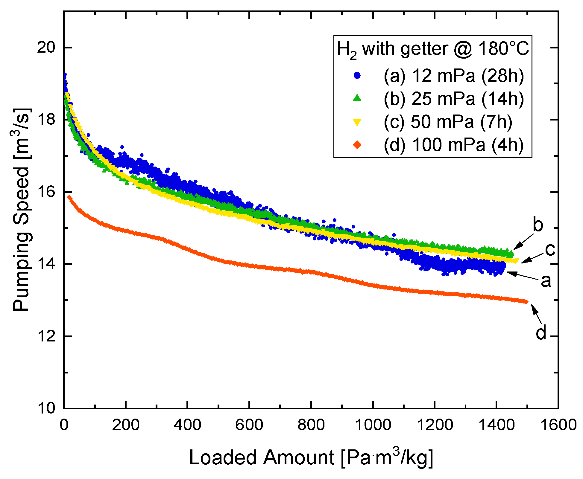
Figure 10 shows the resulting pumping speed for H
2 at a constant getter temperature of 180 °C with the needed sorption duration. It is well known that in the diffusion-limited regime, the pumping speed of a getter decreases with the increasing pressure due to the increasing hydrogen concentration close to the getter surface. In the case of this ZAO
® pump, for operation at 180 °C and pressures of up to 50 mPa, the effect of pressure on the pumping speed is not appreciable, while it becomes significant at 100 mPa. Currently, there is no sound explanation for this non-linear cartridge specific behavior.
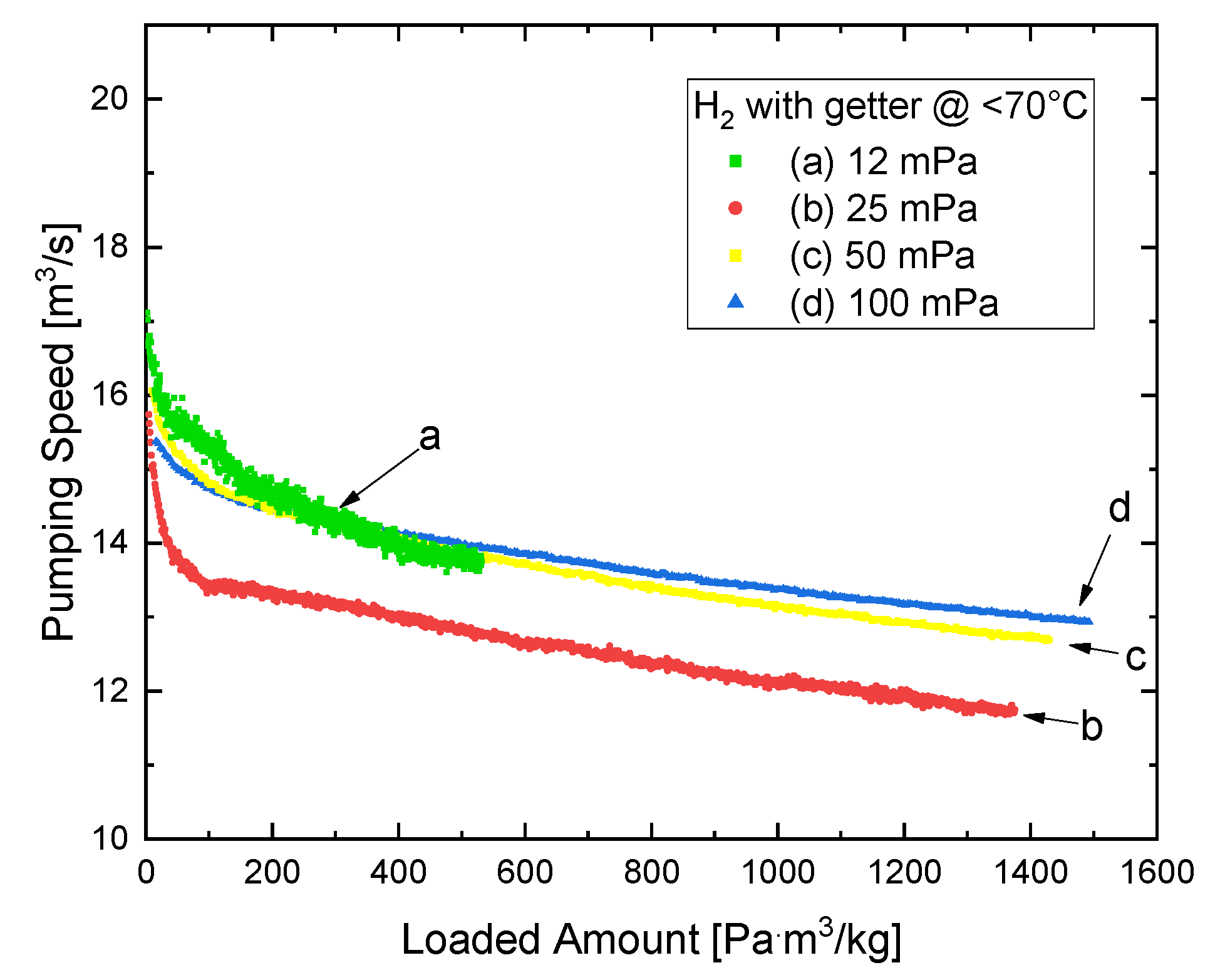
This variation was also tested for a cold getter, meaning temperatures ≤70 °C, and the results are shown in
Figure 11. Quite surprisingly, the dependence with hydrogen pressure is not monotonic. The motivation behind the use of different getter temperatures is explained in the following.
5.2. Getter Temperature Influence
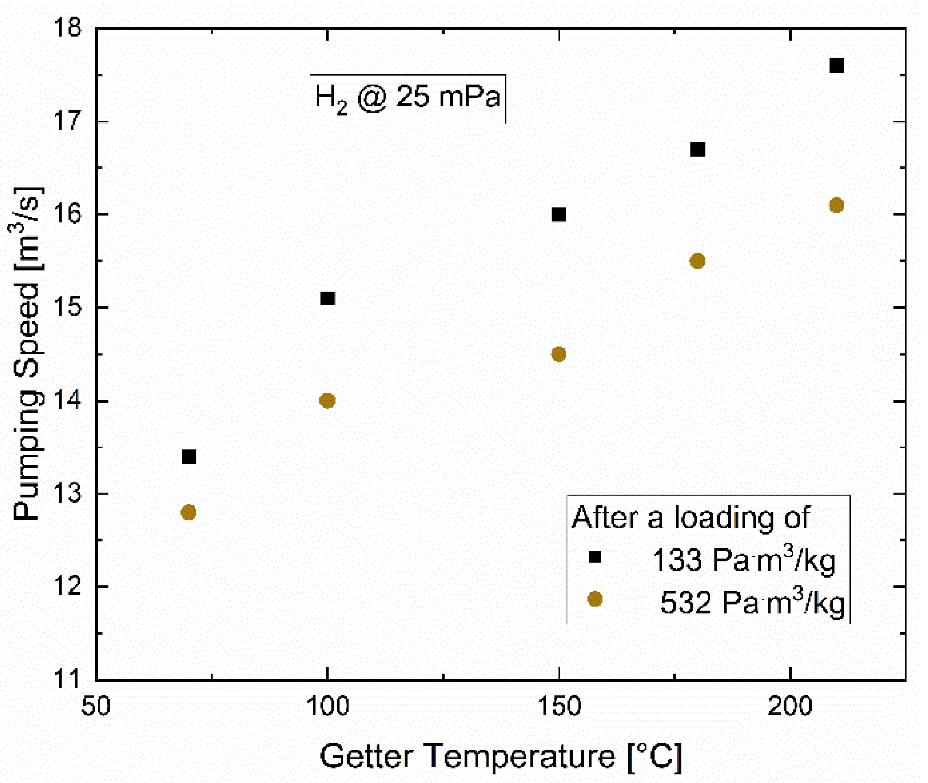
Clearly, the getter is working also at ambient temperature, where it is preferred from a pure energy consumption point of view. However, its capacity for non-hydrogens increases significantly with higher temperatures. Furthermore, its potential capability to preserve the performance for hydrogen under a non-hydrogen impurity background is improved. Hence, the choice of the ideal getter temperature during pumping results from a trade-off, which considers thermal aspects with performance aspects. In support of this, an experimental campaign was conducted at different getter temperatures and the other parameters remained constant. In
Figure 12, the pumping speed values of each of these experiments at a rather low inventory of 133 Pa·m
3/kg are summarized. Based on this, the getter temperature of 180 °C was decided to be chosen for the standard experiments, along with 70 °C (or lower, which is equivalent to the ambient temperature, from a performance point of view). The interpretation of this effect has two aspects. Firstly, the capacity for non-hydrogens increases significantly, preserving an improved performance for hydrogen. Secondly, the pumping speed for hydrogen increases with higher getter temperatures due to a faster diffusion of hydrogen into the bulk, resulting in a smaller concentration close to the surface [
9].
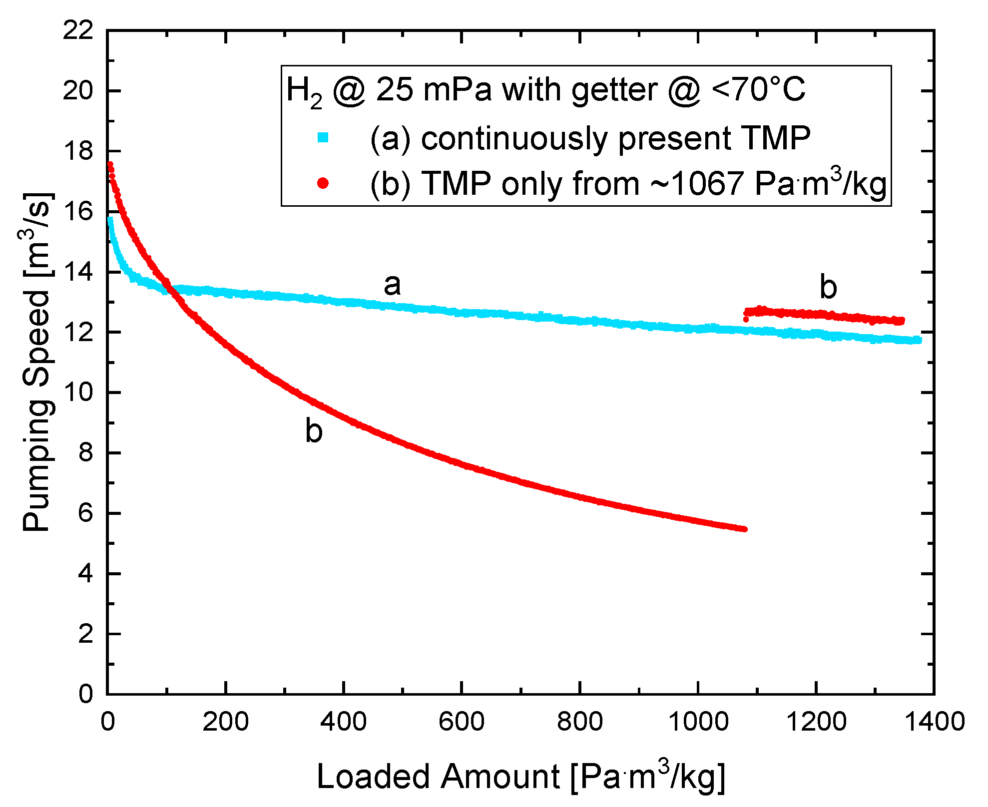
5.3. Background Effect
While ZAO® provides a high pumping speed and capacity for hydrogen, it also sorbs gases, such as N2, CO, CO2 and H2O. However, the sorption mechanism is different, since these species chemically react with the metal alloy and occupy superficial absorption sites, resulting in a reduction in the performance available for hydrogen until the next regeneration. Since in large systems related to the nuclear fusion area, the conditions are less clean than in UHV applications, the non-hydrogenic background is of relevance for the operation of such a pump.
Hence, an experiment was performed to address the question about a potential degradation of the performance by the presence of non-getterable gases besides hydrogen. The temperature was chosen to be cold (<70 °C) in order to emphasize the impact of non-hydrogenics. This experiment did not follow the standard procedure described above, but another scheme, as indicated in
Figure 13: while the getter was pumping H
2, the TMP was separated from the TIMO vessel with the gate valve and, consequentially, a continuous rise of the signal of the pressure gauge (gas independent capacitance manometers) in TIMO was observed. This rise, however, comes from the accumulation of the non-getterable impurities, which add themself to the H
2 partial pressure. Following ~11 h of dosage up to 1067 Pa·m
3/kg, the gate valve was re-opened and the TMP pumped down the partial pressure of non-getterables instantaneously. As shown in
Figure 13, the NEG pumping speed fully recovered to the expected value (see
Figure 11), for the present time and accumulated inventory. Therefore, it can be concluded, that the presence of the high background during sorption did not cause any real reduction in performance for H
2 pumping. Moreover, the role of the TMP in pumping the getterable background species is not relevant for preserving the H
2 pumping speed. The source of the non-getterable gases is the unavoidable low contamination in the gas dosage of a few ppm. It can be assessed that every ppm of non-getterables in the gas supply creates a pumping speed drop of 4% after this long period of 11 h. This strong effect underlines again the need for a continuously running second vacuum system supporting the NEG pump in an application. The difference in the initial pumping speed of the curves is not caused by any background effect of this experiment, but only due to slightly different start inventories.
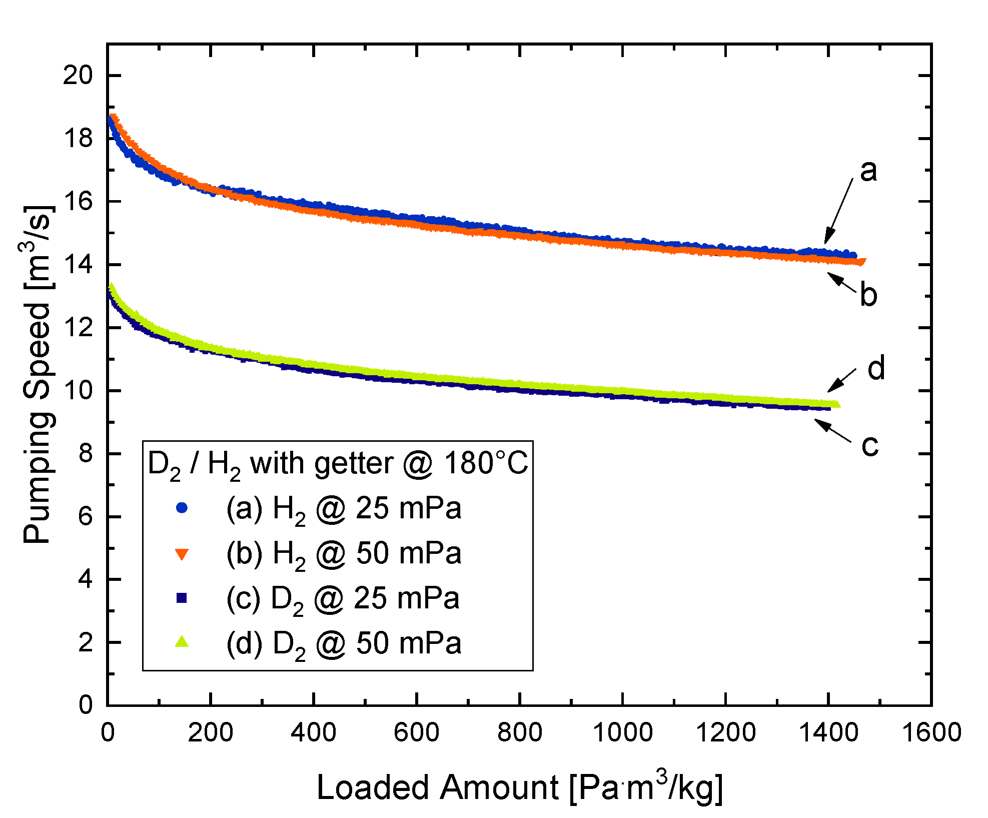
5.4. Isotope Effect
Since a DEMO NBI would operate with D
2 instead of H
2, the isotope effect on the performance was also investigated. While the experiments with H
2 and D
2 were conducted in an identical manner, several aspects, such as the different pumping speeds of the TMP or re-calibration of the mass flow controller had to be considered.
Figure 14 shows the comparison between H
2 and D
2 for a 180 °C getter temperature at two different pressures. It can be seen that the pumping speed for D
2 is ~65–70% of the H
2 related value. Because the pumping speed is proportional to the thermal speed of a gas, and the thermal speed of D
2 is 1⁄√2 ≈ 0.71 of the thermal speed of H
2 at the same temperature, this means that the sticking coefficient, and therefore the chemisorption at the getter material, can be stated as identical for both isotopes.
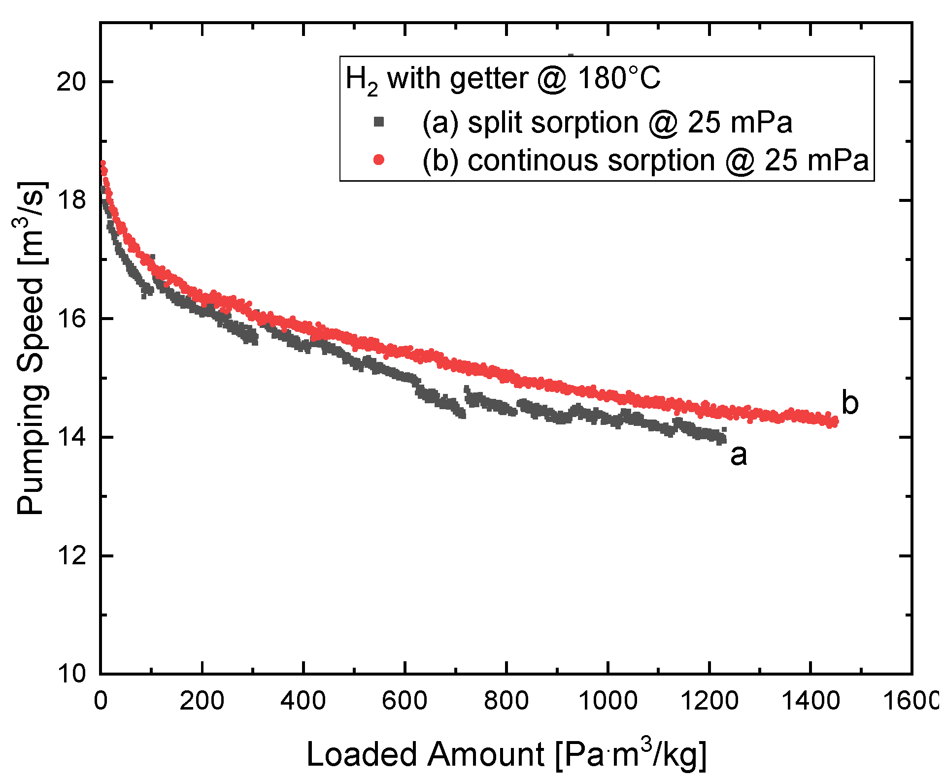
5.5. Continuous vs. Intermittent Pumping Operation
The application in an NBI is characterized by pulsed operation, requiring pumping for 1–2 h with a certain break in between, and that could have an impact. A conceivable effect would be the additional time for the gas arriving at the getter surface to diffuse into the getter bulk and therefore decrease the H
2 concentration close to the surface.
Figure 15 shows the result of a dedicated experiment and demonstrates that there is no such positive effect. Contrarily, there is a trend to a small reduction of the pumping speed for split sorption operation, which is caused by the doubled experimental time in which more background gas (as N
2 or CO/CO
2 from TIMO outgassing and leak rate) was pumped by the getter, reducing slightly the performance for H
2.
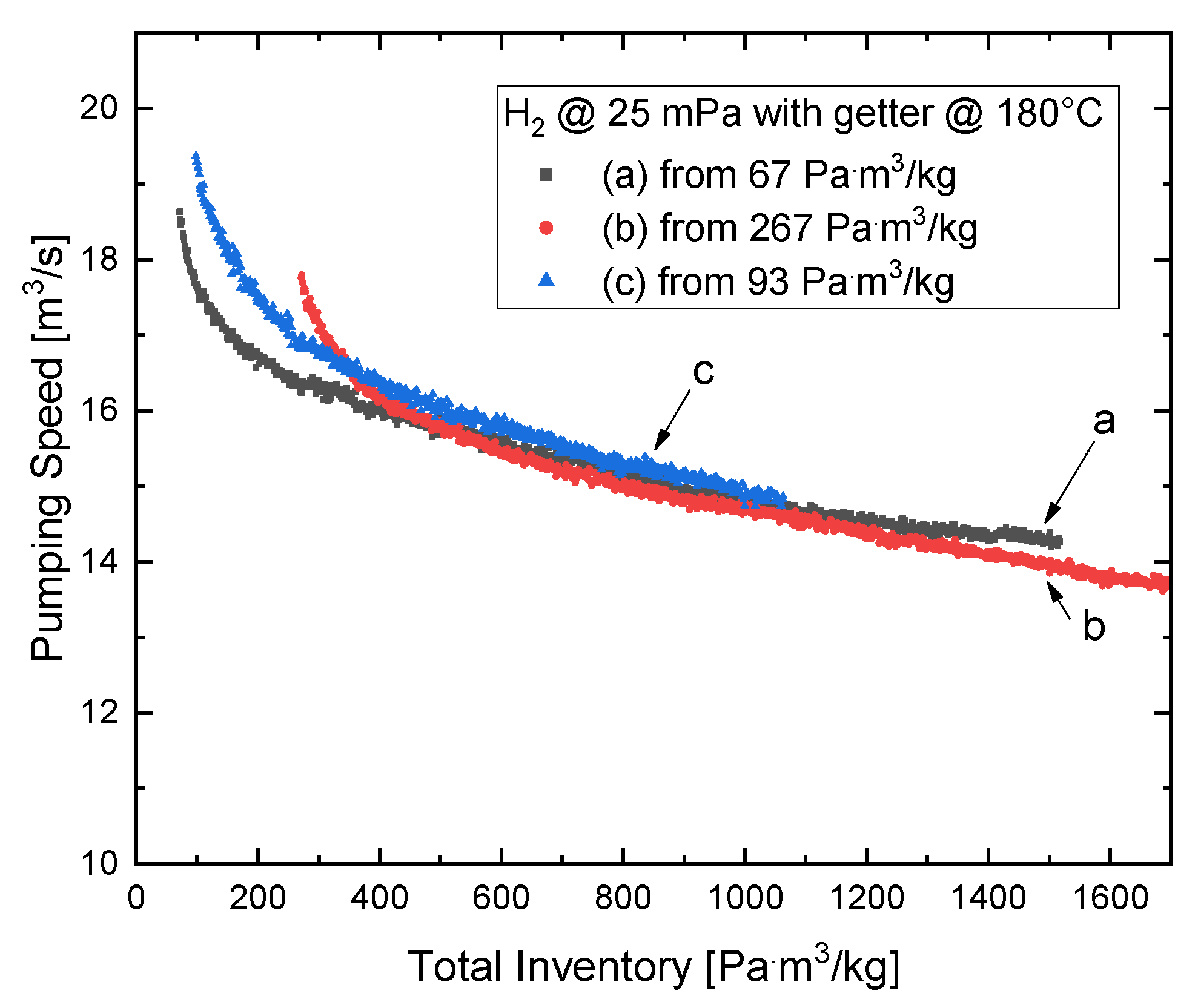
5.6. Starting Inventory Influence and Repeatability
The effect of decreasing the pumping speed with the growing inventory has already been shown. Additionally to this effect, experiments with a different starting inventory, remaining from the previous regeneration, have been compared. In
Figure 16, it can be seen that the behavior—in terms of the total inventory—is comparable with the curves shown in
Figure 10, as long as the different starting conditions of the getter are properly considered (by shifting along the loading/inventory x-axis). This also implies a very good repeatability of the NEG pump performance.
5.7. Overview Map of the Performance
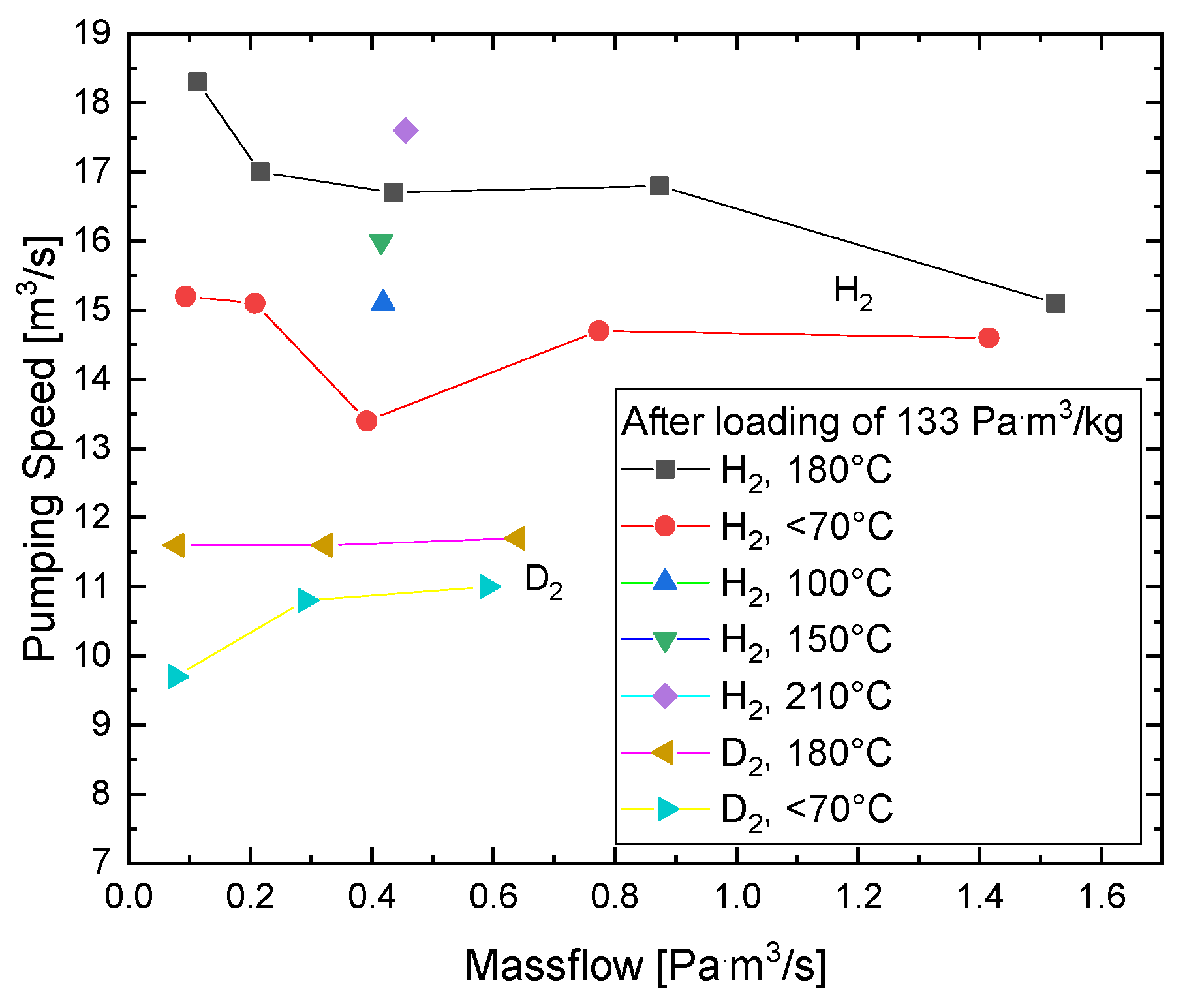
In order to summarize the different aspects influencing the behavior of the NEG pump,
Figure 17 shows a full map of experimentally determined pump performances for the getter loaded with 133 Pa·m
3/kg as an arbitrarily selected value for a low inventory.
5.8. Results on the Thermal Aspects, Operation and Control
In addition to the full experimental characterization of the performance of the NEG pump, a second major goal was to acquire the knowledge and experience on how to operate such a large pump on a further extended scale. This comprises aspects, such as thermal management, getter temperature control, resulting thermal inhomogeneities between the different cartridges and along them, and the development, use and optimization of the control software. Furthermore, information on the robustness of the getter in the systems of limited cleanliness and detailed experience, was gained [
10]. The following main improvements can be stated and conclusions can be drawn from the entire campaign. The master-slave concept (see
Section 3) works excellently and gives the possibility to group any number of cartridges in a large future NEG pump for optimal temperature control during sorption and regeneration. The developed pump, using only metal and ceramic components besides the cartridges, was perfectly capable to withstand the harsh conditions. Thermal inhomogeneities among the different cartridges have been reduced to <5% by improved temperature settings in the master-slave based control software. The remaining thermal inhomogeneities, not between the different cartridges, but from the different sides of an outer one, are fully acceptable and do not influence the equal contribution of all cartridges in the pump: the measured temperatures did not vary more than 5%. Regarding software and control, the entire campaign lead to many lessons learned from the PID characteristics, temperature read outs, master-slave dependencies, automatic switches after transient phases (heating, cool down), safety monitoring of the TIMO hydrogen inventory and control stability in general. At the end, it can be concluded that the entire system matured enormously and is now much closer for large-scale application.
6. Regeneration Aspects
6.1. Regeneration Experiments
In general, the regeneration is driven by the temperature of the getter that, together with the bulk H
2 concentration, determines the pressure at which the release of the gas takes place. Then, the speed of a regeneration depends on the availability of an auxiliary vacuum pump with a large pumping speed. The depth of a regeneration, i.e., the remaining hydrogen inventory, is given by the pressure achieved at the end of the process: the lower the pressure, the smaller the residual hydrogen amount. The regenerations have been performed measuring the pressure inside the TIMO facility while the getter was heated up and the gas was pumped out of the vessel by the TMP with a known effective pumping speed for H
2 and D
2. Applying the pumping equation to this system, the throughput of gas, which leaves the NEG pump, was determined. Regarding the practical aspects, the regeneration process had to reflect two aspects, namely the quick extraction of the gas to save time, but also the limitation of the gas release to respect a maximum pressure for TMP protection.
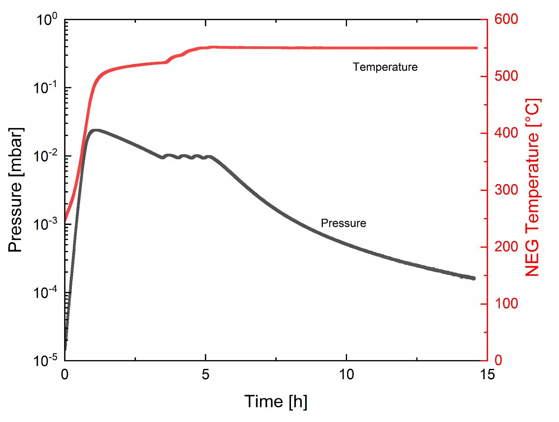
Figure 18 shows a typical regeneration at 550 °C. In the time period between 1 h and 5 h the needed power regulation to limit the pressure to ~1 Pa can be seen. With this active management, the regulation would work for every individual environment.
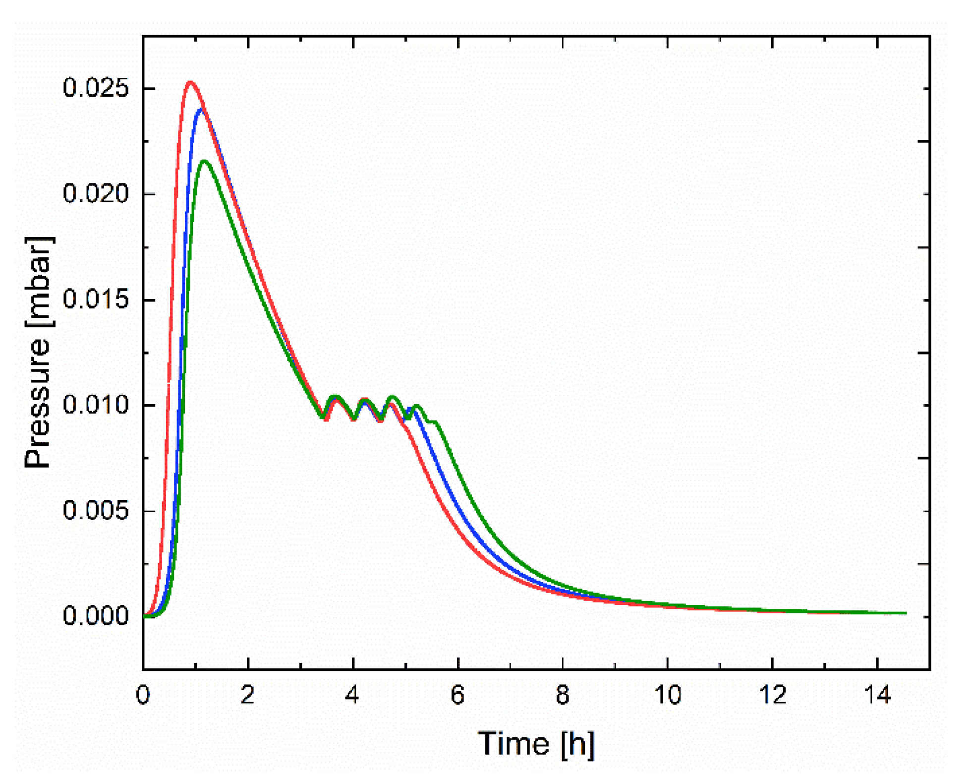
For comparability of the experiments, similar starting conditions were needed. This means that every regeneration was carried out, such that the remaining residual inventory was 67 Pa·m
3/kg. The amount of gas desorbed by the NEG pump was calculated by the pressure measurements and the known TMP pumping speed as a function of pressure. The uncertainties of these two quantities contribute to an uncertainty of the quantity of extracted gas in the order of 10–15%.
Figure 19 shows the comparison of three regenerations under identical conditions and the histories to demonstrate the very good repeatability of the regeneration process under the chosen procedure.
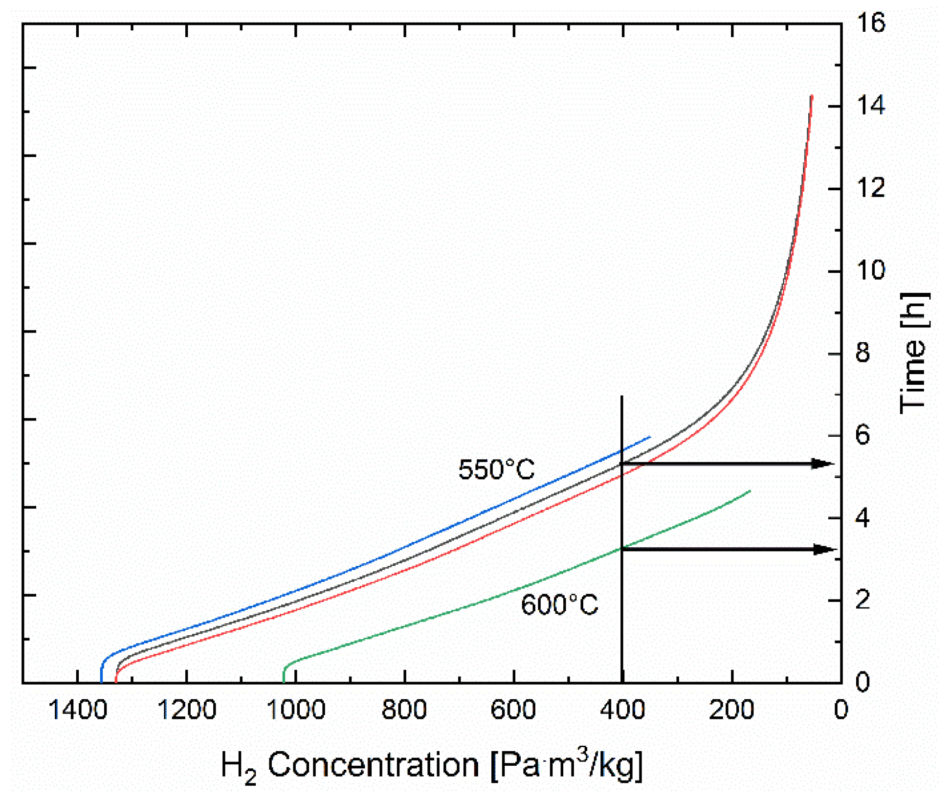
The influence of the different regeneration temperatures on the needed regeneration time was also investigated, and is shown in
Figure 20. It can be seen that, for example, a regeneration at 550 °C reduces, in the given conditions in TIMO, the hydrogen inventory in the getter to the remaining 933 Pa·m
3/kg in 2 h or 533 Pa·m
3/kg in 4–4.5 h.
6.2. Regeneration Prediction
A major additional goal of the experiments on regeneration was to develop an easy and validated method to predict a regeneration, in terms of evolution and duration for all potential future configurations or environments.
Sieverts’ law describes the relation between hydrogen concentration
c [Pa·m
3/kg] within the getter and the corresponding equilibrium pressure
p [Pa]. From a practical point of view it can be written as
where
A = 3.64 and
B = 7290 K for H
2 are the experimental constants for ZAO
®, and
T [K] is the getter temperature. By fitting the regeneration data with Sieverts’ law, it is possible to find an effective temperature
Teff that best describes the evolution of the process.
Teff accounts mainly for temperature gradients and it is specific for the cartridge array geometry of the pump under investigation.
Using Sievert’s law, it is possible to estimate the regeneration time
considering that sorption and regeneration move between the same gas concentrations
where
mNEG is the mass of NEG material [g],
Treg is the regeneration temperature [K],
Saux is the auxiliary pumping speed [L/s],
c0 is the gas concentration inside the NEG at the end of the regeneration [Pa·m
3/kg] and
c1 is the gas concentration inside the NEG at the beginning of the regeneration [Pa·m
3/kg].
Regenerations performed during the experimental campaign were fitted with a model based on Sieverts’ law, with the aim of estimating the best effective temperature to match the extracted hydrogen amount. In particular, the analysis was carried out on sets of data at a thermal equilibrium (i.e., once the target regeneration temperature was reached). In order to provide a more robust basis for such an analysis, a few regenerations were performed with a different recipe, i.e., carrying out the whole hydrogen extraction process at a constant temperature. This was made possible by isolating the system from the TMP until the target temperature was reached, then opening the TMP to pump hydrogen away.
Values of Teff obtained from fitting the standard regeneration curves were coherent with values found from fitting regenerations made at a constant temperature: values obtained are lower than the nominal T (Tnom = 550 °C) and span between 531 °C and 545 °C. For example, it results that the temperature that best accounts for the duration of the real test, which lasted about 10 h, regenerating the NEG from 533 Pa·m3/kg (4 Torr∙L/g) down to about 67 Pa·m3/kg (0.5 Torr∙L/g), is 535.5 °C, giving a Teff/Tnom ratio equal to 0.974.
For the regeneration of D2, the same procedure was carried out, finding a Teff/Tnom ratio equal to 0.958.
With these relations, and especially the experimentally determined Teff/Tnom ratio completed, a simple and validated tool is now available to predict the regeneration behavior of a future large NEG pump with similar geometry in any vacuum system and for any desired or required loading-unloading cycles or inventories.
7. Simulations Exploiting the Experiments
Subsequently to the entire experimental campaign, a simulation approach was followed with the aim of extracting the sticking factor of the getter surface and of the cartridge arrangement. The motivation here is to evaluate the capability for future possible changes in the arrangement, in terms of pumping speed and sorption homogeneity limiting the experimental effort for every potential design modification.
To perform this task, the KIT in-house test particle Monte Carlo code ProVac3D [
11] was used. This code is also routinely used to deal with the required gas density profiles along the beam axis of an NBI and to extract a required capture coefficient of a conceptual pumping system [
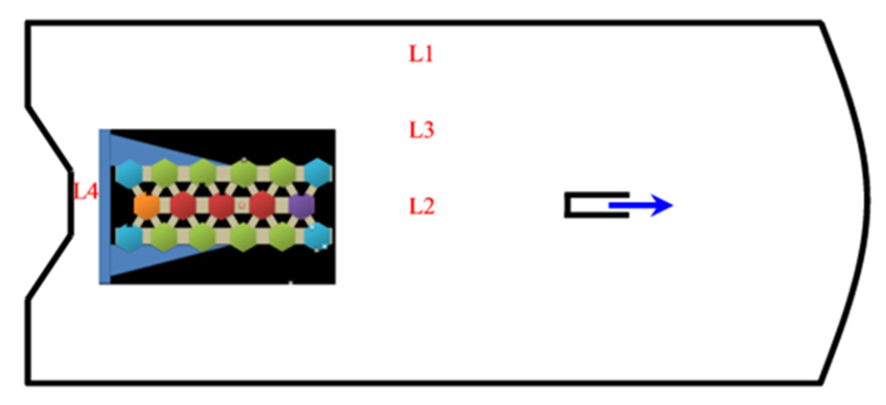
12]. A fully detailed model of the TIMO vessel and the NEG pump inside was established for ProVac3D (
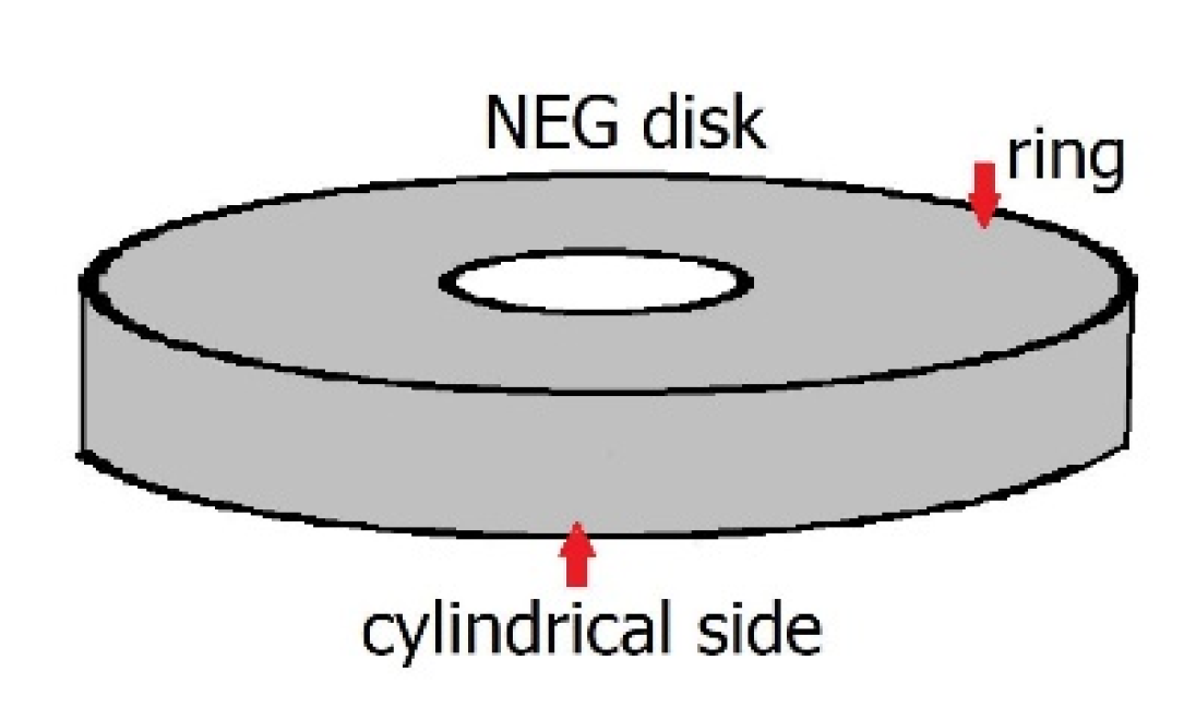
Figure 21). This means that for the full representativeness and significance, all details of the NEG pump had to be replicated in this model. Consequentially, it comprises all 4590 getter disks with upper and lower sides with a ring surface each (
Figure 22), the mounting structure and all other components of relevance, such as the protection cages around every cartridge, which in total amount to more than 14,000 surfaces. This model was obviously only manageable via high performance computing. The simulations were run on the Marconi-Fusion machine with 10,000 cores.
With the established model, the simulation was performed iteratively adjusting the sticking factor of the getter surface in the model for a constant condition of H2, a 25 mPa pressure and getter at 180 °C. The pressure, which resulted from a simulation, was compared with the experimental finding, and to reduce the difference, the sticking factor was adjusted for the next simulation. Following this iteration, a perfect match between the simulated pressure and the experimentally determined one was reached and so the real sticking factors of the getter disks and the cartridges were found.
The outcome of this task is a capture factor of 7% for a complete cartridge. It could also be shown that the sticking factor of the getter is identical for H
2 and D
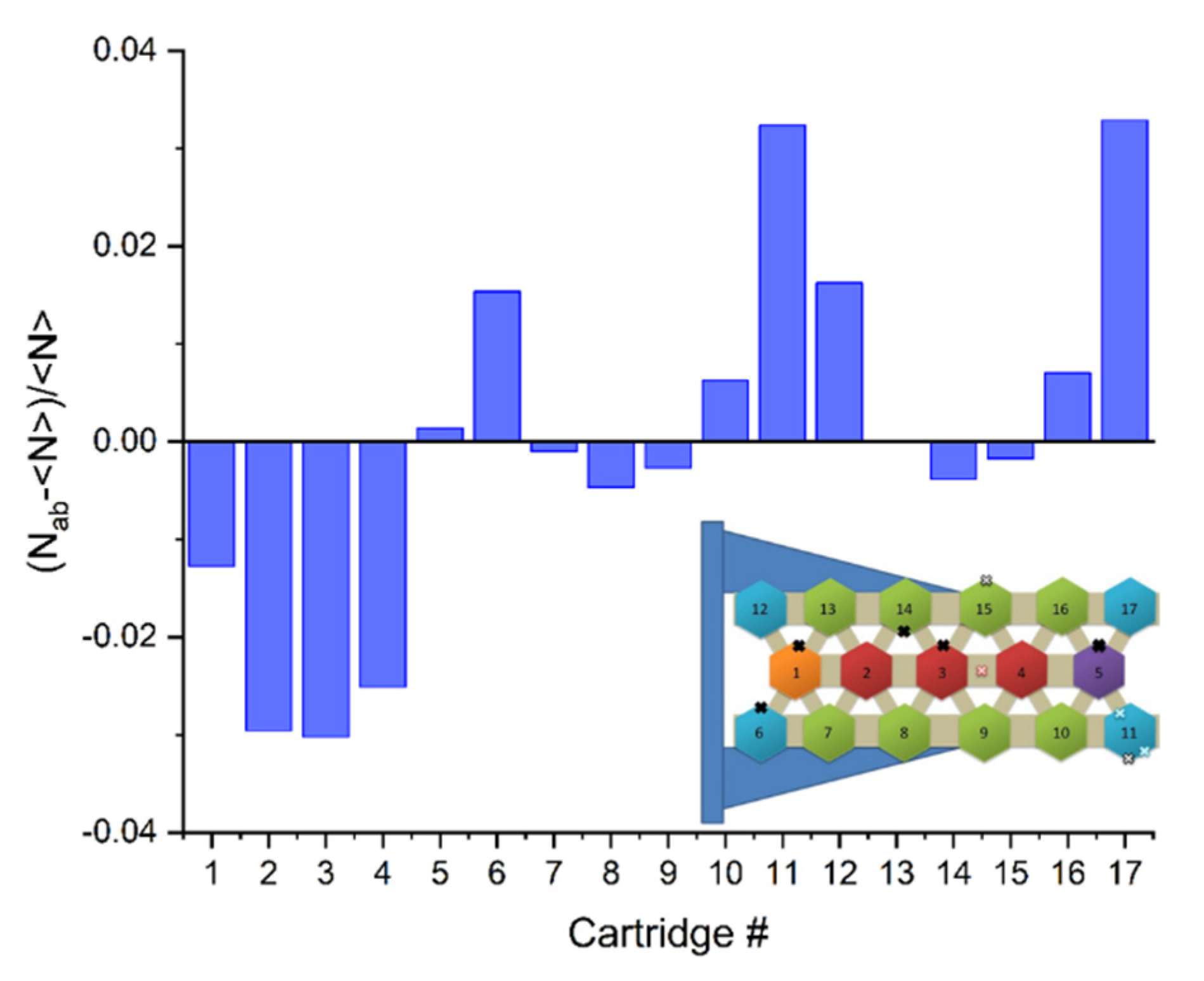
2. The investigated shadowing effect between the 17 cartridges in the investigated arrangement (numbering see
Figure 5), namely the mechanism that a neighboring cartridge could hinder the gas flow to the next one while a cartridge at the pump edge is more accessible, was found with ±3% being negligible.
Figure 23 shows the ratio of (N
ab − <N>)/<N>, where N
ab is the absorbed number of test particles by each NEG cartridge and <N> the average number of caught particles for all cartridges, and it is easy to see the shadowing effect on the cartridges:
The cartridges on the lower line (#6–11) are almost identical to the ones on the upper line (#12–17);
Because of the shadowing effect, the performance of the cartridges in the middle of each line (#2–4, 7–9, 13–15) are worse than the average (negative ratio);
The shadowing effect on the cartridges on the middle line is bigger than that of the cartridges on the lower and upper lines;
There is also a beaming effect in the flow direction: for the cartridges on each line, the cartridges close to the gas source at the right side (#5, 11 and 17) absorb more molecules than the other cartridges on the same lines.
With the outcome of this simulation task, the influence of the cages and the potential aspect of shadowing for tightly packed cartridges can be considered. This means that for the stack-based arrangement, the tool for estimation of the expected pumping speed and sorption (in-)homogeneity is now available. With the match between the simulation and experiment for the arrangements of our interest, we also achieved a successful validation. The resulting capability to rely on the simulation and to limit the effort of experiments, gives the freedom to vary many potential arrangements for NEG pumps for application, as has been described in this paper.
8. Conclusions
The outcome of this experimental campaign with an NEG pump of novel size, containing 15.6 kg of ZAO®, is a complete view in neutral beam injection systems on pumping performance, and how they depend on pressure, inventory, temperature, background and isotopes, but also on the uniformity of temperature and gas load distribution along such a large pump. Another very important result in view of the potential later application, is all of the experience gained in the operation, control and software tools. The results presented here are a significant contribution to increase the technical readiness level of a getter-based pumping system for an NBI.
The capture coefficient of the used ZAO® cartridge was extracted numerically from a representative experiment. Therefore, one further major outcome of this work is the capability to estimate the expected pumping behavior of the arrangement by a Monte Carlo calculation that involves the found numbers. With this tool in hand, a scale-up concept for an entire NBI pumping system on the ZAO® basis, asking for thousands of cartridges, can be developed limiting the need for further elaborate experiments.
It can be summarized that the ZAO® material arranged in cartridges and forming a large pump, showed pumping speeds, capacity and cycling capability that are very promising to be able to replace the cryopumps in a DEMO NBI. Work has to be continued to complete a comprehensive concept at the engineering level, including the secondary pumping system for quick regeneration and optimization of the power supply system. However, it can be concluded that the NEG technology based on ZAO®, is a candidate for NBI pumping.
Author Contributions
Conceptualization, S.H., C.D. and F.S.; Methodology, S.H., F.S. and E.S.; Software, X.L., B.B., E.S. and M.S.; Validation, F.S.; Formal analysis, F.S., E.S. and M.S.; Investigation, S.H., X.L., F.S., M.M., E.S. and M.S.; Resources, C.D.; Data curation, S.H. and F.S.; Writing—original draft, S.H.; Writing—review & editing, S.H., C.D., T.G., F.S., M.M., E.M., P.M., E.S., M.S. and P.S.; Visualization, S.H.; Supervision, C.D.; Project administration, S.H., C.D., T.G., P.M. and P.S.; Funding acquisition, C.D. and P.M. All authors have read and agreed to the published version of the manuscript.
Funding
This research was funded by the European Union via the Grant Agreement No 101052200—EUROfusion. We acknowledge support by the KIT-Publication Fund of the Karlsruhe Institute of Technology.
Data Availability Statement
The data presented in this study are available on request from the corresponding author.
Acknowledgments
The authors would like to thank members of the Vacuum Department at KIT and the involved colleagues at SAES for their invaluable assistance. This work has been carried out within the framework of the EUROfusion Consortium, funded by the European Union via the Euratom Research and Training Programme (Grant Agreement No 101052200—EUROfusion). Views and opinions expressed are however those of the authors only and do not necessarily reflect those of the European Union or the European Commission. Neither the European Union nor the European Commission can be held responsible for them. This work is also supported by the EUROfusion project VAC_ND in the supercomputer MARCONI-FUSION at CINECA, Italy.
Conflicts of Interest
The following authors declare no conflict of interest: S.H., C.D., T.G., X.L., E.S. and M.S. The following authors declare a conflict of interest in being employees of SAES Getters S.p.A., which produces and sells Non-Evaporable Getter pumps of the type described in the present paper: F.S., M.M., B.B., E.M. and P.M. The authors F.S., P.M. and P.S. declare a conflict of interest in having the patent #WO 2015198235—Getter Pumping System, issued to SAES Getters S.p.A.
References
- Sonato, P.; Agostinetti, P.; Fantz, U.; Franke, T. Conceptual design of the beam source for the DEMO Neutral Beam Injectors. New J. Phys. 2016, 18, 125002. [Google Scholar] [CrossRef]
- Dremel, M.; Day, C.; Luo, X.; Hanke, S. Cryopump design development for the ITER Neutral Beam Injectors. Fusion Eng. Des. 2009, 84, 689–693. [Google Scholar] [CrossRef]
- Hemsworth, R.; Boilson, D.; Blatchford, P.; Dalla Palma, M.; Chitarin, G.; de Esch, H.P.L.; Geli, F.; Dremel, M.; Graceffa, J.; Marcuzzi, D. Overview of the design of the ITER heating neutral beam injectors. New J. Phys. 2017, 19, 025005. [Google Scholar] [CrossRef]
- Siviero, F.; Caruso, L.; Porcelli, T.; Mura, M.; Maccallini, P.; Manini, E.; Sartori, M.; Siragusa, M.C.; Day, C.; Sonato, P. Characterization of ZAO® sintered getter material for use in fusion applications. Fusion Eng. Des. 2019, 146, 1729–1732. [Google Scholar] [CrossRef]
- Sartori, E.; Siragusa, M.; Sonato, P.; Siviero, F.; Mura, M.; Maccallini, E.; Ferrara, A.; Manini, P.; Hanke, S.; Day, C. Development of Non Evaporable Getter pumps for large hydrogen throughput and capacity in high vacuum regimes. Vacuum, 2023; submitted. [Google Scholar]
- Siragusa, M.; Sonato, P.; Visentin, M.; Mura, M.; Siviero, F.; Viale, L.; Maccallini, E.; Day, C.; Hanke, S.; Sartori, E. Conceptual design of scalable vacuum pump to validate sintered getter technology for future NBI application. Fusion Eng. Des. 2019, 146, 87–90. [Google Scholar] [CrossRef]
- Siragusa, M.; Sartori, E.; Mura, M.; Siviero, F. Numerical simulation of experimental tests performed on ZAO® non-evaporable-getter pump designed for neutral beam injector applications. Rev. Sci. Instrum. 2020, 91, 023501. [Google Scholar] [CrossRef]
- Haas, H.; Day, C.; Mack, A.; Methe, S.; Boissin, J.C.; Schummer, P.; Murdoch, D.K. Test facility TIMO for testing the ITER model pump. In Proceedings of the IAEA Fusion Energy Conference, Yokohama, Japan, 18–24 October 1998; International Atomic Energy Agency: Vienna, Austria, 1999; pp. 1077–1080. [Google Scholar]
- Ferrario, B. Contributing in Foundations of Vacuum Science and Technology; Lafferty, J.M., Ed.; John Wiley & Sons, Inc.: New York, NY, USA, 1998; ISBN 0-471-17593-5. [Google Scholar]
- Siviero, F.; Caruso, L.; Mura, M.; Maccallini, E.; Manini, P.; Sartori, E.; Siragusa, M.; Hanke, S.; Day, C.; Sonato, P. Robustness of ZAO based NEG pump solutions for fusion applications. Fusion Eng. Des. 2021, 166, 112306. [Google Scholar] [CrossRef]
- Luo, X.; Day, C. 3D Monte Carlo vacuum modeling of the neutral beam injection system of ITER. Fusion Eng. Des. 2010, 85, 1446–1450. [Google Scholar] [CrossRef]
- Luo, X.; Scannapiego, M.; Day, C.; Sakurai, S. Assessment of the JT-60SA divertor cryopump performance. Fusion Eng. Des. 2018, 136, 467–471. [Google Scholar] [CrossRef]
Figure 1.
Matrix of the main aspects of interest, experimentally investigated on different scales of pump sizes. Each disk has a 25 mm diameter, 2 mm thickness and contains 3.5 g of ZAO® getter.
Figure 1.
Matrix of the main aspects of interest, experimentally investigated on different scales of pump sizes. Each disk has a 25 mm diameter, 2 mm thickness and contains 3.5 g of ZAO® getter.
Figure 2.
The three different configurations investigated for an NEG pump of relevant scale.
Figure 2.
The three different configurations investigated for an NEG pump of relevant scale.
Figure 3.
Simulated gas uniformity of the three investigated configurations.
Figure 3.
Simulated gas uniformity of the three investigated configurations.
Figure 4.
Full NEG pump assembled at the TIMO (test facility for the ITER model pump). The main flange is ready for installation.
Figure 4.
Full NEG pump assembled at the TIMO (test facility for the ITER model pump). The main flange is ready for installation.
Figure 5.
Pump scheme showing all 17 cartridges grouped in five master-slave sections (light blue = corner, green = outer edge, red = innermost, orange = inner edge, purple = inner edge but with a different heater design for testing purposes). The crosses represent the thermocouples for the temperature reading, the cartridge numbering is relevant for
Section 7.
Figure 6.
Schematic diagram of the TIMO facility with gas dosage, pressure gauges, auxiliary pumping system and the getter pump itself (with thermocouples (TC) and filaments).
Figure 6.
Schematic diagram of the TIMO facility with gas dosage, pressure gauges, auxiliary pumping system and the getter pump itself (with thermocouples (TC) and filaments).
Figure 7.
TIMO facility at KIT in the closed position before the completion of all connections at the main flange (pressure reading equipment, exhaust pipes and NEG pump cabling).
Figure 7.
TIMO facility at KIT in the closed position before the completion of all connections at the main flange (pressure reading equipment, exhaust pipes and NEG pump cabling).
Figure 8.
Bird’s eye view of the TIMO facility before the main flange insulation for the vessel bake out after air exposure.
Figure 8.
Bird’s eye view of the TIMO facility before the main flange insulation for the vessel bake out after air exposure.
Figure 9.
TIMO during installation of the developed NEG pump.
Figure 9.
TIMO during installation of the developed NEG pump.
Figure 10.
Pumping speed curves at different pressures with the growing inventory of H2 with ZAO® at 180 °C. Different pressures were established by different constant mass flows resulting in different durations to reach the same inventory. The effect of the decreasing pumping speed at higher pressures, caused by diffusion limitation from the getter surface into the bulk, becomes significant only for pressures >50 mPa.
Figure 11.
Pumping speed curves at different pressures with a growing inventory of H2 with ZAO® at temperatures of 70 °C or below.
Figure 11.
Pumping speed curves at different pressures with a growing inventory of H2 with ZAO® at temperatures of 70 °C or below.
Figure 12.
Comparison of the pumping speed results depending on the getter temperature during sorption for low and moderate inventories.
Figure 12.
Comparison of the pumping speed results depending on the getter temperature during sorption for low and moderate inventories.
Figure 13.
Pumping speed comparison between the normal experimental scheme with TMP present and a run without TMP, and the increasing pressure in TIMO due to background gas pressure rise. A full recovery of the pumping speed after such a non-ideal condition is demonstrated.
Figure 13.
Pumping speed comparison between the normal experimental scheme with TMP present and a run without TMP, and the increasing pressure in TIMO due to background gas pressure rise. A full recovery of the pumping speed after such a non-ideal condition is demonstrated.
Figure 14.
Isotope effect on the pumping speed for H2 and D2.
Figure 14.
Isotope effect on the pumping speed for H2 and D2.
Figure 15.
Pumping speed comparison for the continuous and split dosage (1 h sorption, 1 h break) of H2 with ZAO® at 180 °C.
Figure 15.
Pumping speed comparison for the continuous and split dosage (1 h sorption, 1 h break) of H2 with ZAO® at 180 °C.
Figure 16.
Pumping speed curves at comparable conditions, but starting at different inventories, which remain from differently deep previous regenerations.
Figure 16.
Pumping speed curves at comparable conditions, but starting at different inventories, which remain from differently deep previous regenerations.
Figure 17.
Full map of the pumping speed results for a getter loaded only with 133 Pa·m3/kg under different mass flows, getter temperatures and isotopes.
Figure 17.
Full map of the pumping speed results for a getter loaded only with 133 Pa·m3/kg under different mass flows, getter temperatures and isotopes.
Figure 18.
Typical regeneration process regarding the getter temperature and related gas release which increases the pressure inside TIMO under continuous TMP extraction.
Figure 18.
Typical regeneration process regarding the getter temperature and related gas release which increases the pressure inside TIMO under continuous TMP extraction.
Figure 19.
Comparison of three H2 regenerations performed with the same nominal temperature of 550 °C and the feedback control of the heating to demonstrate repeatability.
Figure 19.
Comparison of three H2 regenerations performed with the same nominal temperature of 550 °C and the feedback control of the heating to demonstrate repeatability.
Figure 20.
Trend of the gas inventory inside the getter during regenerations performed at different temperatures (represented by different colors). For example, the regeneration reduced to an inventory of 400 Pa·m3/kg will take 5–6 h at 550 °C, but only 3 h at 600 °C.
Figure 20.
Trend of the gas inventory inside the getter during regenerations performed at different temperatures (represented by different colors). For example, the regeneration reduced to an inventory of 400 Pa·m3/kg will take 5–6 h at 550 °C, but only 3 h at 600 °C.
Figure 21.
Sketch of the TIMO facility modeled in ProVac3D containing the NEG pump and showing the gas inlet position and direction.
Figure 21.
Sketch of the TIMO facility modeled in ProVac3D containing the NEG pump and showing the gas inlet position and direction.
Figure 22.
Getter disk replicated for the TPMC model simplifying the geometry to an upper and lower ring surface, and a cylindrical side representing the disk thickness.
Figure 22.
Getter disk replicated for the TPMC model simplifying the geometry to an upper and lower ring surface, and a cylindrical side representing the disk thickness.
Figure 23.
Comparison of the gas loads individually caught by the different cartridges (for numbering, see inlay or
Figure 5) in the ProVac3D model. Nab is the number of particles caught by a cartridge and <N> is the average number of caught particles for all cartridges. It can be seen that the shadowing effects between the cartridges are very small with a 3% maximum.
| Disclaimer/Publisher’s Note: The statements, opinions and data contained in all publications are solely those of the individual author(s) and contributor(s) and not of MDPI and/or the editor(s). MDPI and/or the editor(s) disclaim responsibility for any injury to people or property resulting from any ideas, methods, instructions or products referred to in the content. |
© 2023 by the authors. Licensee MDPI, Basel, Switzerland. This article is an open access article distributed under the terms and conditions of the Creative Commons Attribution (CC BY) license (https://creativecommons.org/licenses/by/4.0/).


 ,
, 


