Abstract
For the cooperative operation of networked microgrids, a distributed energy management considering network operational objectives and constraints is proposed in this work. Considering various ownership and privacy requirements of microgrids, utility directly interfaced distributed energy resources (DERs) and demand response, a distributed optimization is proposed for obtaining optimal network operational objectives with constraints satisfied through iteratively updated price signals. The alternating direction method of multipliers (ADMM) algorithm is utilized to solve the formulated distributed optimization. The proposed distributed energy management provides microgrids, utility-directly interfaced DERs and responsive demands the opportunity of contributing to better network operational objectives while preserving their privacy and autonomy. Results of numerical simulation using a networked microgrids system consisting of several microgrids, utility directly interfaced DERs and responsive demands validate the soundness and accuracy of the proposed distributed energy management. The proposed method is further tested on a practical two-microgrid system located in Adjuntas, Puerto Rico, and the applicability of the proposed strategy is validated through hardware-in-the-loop (HIL) testing.
1. Introduction
Microgrids, as an efficient form of providing clean, low-cost and sustainable energy to consumers, have been accepted by an increasing number of utilities in recent years [1]. Besides providing clean and reliable energy, microgrids have the capability of participating in voltage and frequency regulation [2,3], inertia response [4], etc. In addition, by transforming into islanded operation, microgrids could survive widespread power outages caused by extreme weather events with a high probability, and thus effectively improve the resilience of distribution grids [5]. As a result, microgrids have been increasingly deployed worldwide [6]. As modern utility grids transition from the traditional centralized structure into a distributed structure with ever-denser microgrids, distributed energy resources (DERs), and controllable loads, networked microgrids, formulated by connecting adjacent microgrids and properly coordinating their controls, could achieve better efficiency and resilience than single microgrids or multiple independent microgrids. For this reason, networked microgrids have attracted growing attention [7]. The existing literature on the coordination of networked microgrids and DERs is generally in two groups: centralized and distributed [8,9]. Centralized energy management normally follows a multi-layer hierarchical structure. Two-layer hierarchical energy management is proposed for promoting the consumption of renewable generation in distribution networks in [10]. The lower layer minimizes the operation cost and maximizes renewable energy utilization while the upper layer minimizes feeder losses and bus voltage deviations through an optimal power flow. Similarly, two-layer energy management is designed for voltage regulation and power balancing between phases by coordinating multiple solid-state power substations in [11]. In [12], a generalized multi-layer hierarchical scheduling strategy is designed for nested microgrids. A semidefinite programming (SDP) convex relaxation model is presented for the dispatch of networked microgrids in [13]. Given the uncertainties of renewable generation, multi-level stochastic programming models have been proposed for the scheduling of utility grids with high renewable generation penetrated microgrids [14,15]. Robust optimization-based solutions have been proposed in [16,17]. Centralized energy management has the advantages of straightforwardness, easy implementation and achievable global optimality. However, centralized methods are usually subject to scalability and privacy challenges considering the large number of microgrids, DERs and responsive loads with various ownerships. On the contrary, distributed energy management methods are easily scalable and preserve the privacy of individual local controllers, thus attracting increasing attention. Traditionally, a multi-agent system (MAS) has been used for peer-to-peer trading between microgrids [18], but this method usually overlooks the underlying distribution network. Dual decomposition has also been proposed for energy trading among entities with different objectives and constraints [19,20]. Although dual decomposition could preserve the privacy of participants and enable parallel computation of subproblems, it has poor convergence, especially for nonconvex problems. To improve this situation, the alternating direction method of multipliers (ADMM) has been proposed by adding an augmented Lagrange term to drive the converge [21,22,23,24,25]. In particular, Refs. [23,24,25] model the distribution network as a second-order cone by convex relaxation. Nevertheless, the network operational objectives, such as voltage regulation, network power loss reduction, power factor improvements, etc., are not incorporated. In addition, the utility grid directly interfaced DERs and responsive loads have been ignored. The coordination of multiple microgrids is modeled as a game in [26]. The optimal solution requires finding the Nash equilibrium. Consensus-based algorithms have also been proposed for energy trading in networked microgrids assuming linear marginal cost functions of the microgrids [27]. However, the marginal cost functions of microgrids are usually nonlinear in practice due to the startup and shutdown of DERs. To consider the uncertainties of renewable generation and loads in the ADMM algorithm, an adjustable robust optimization model is proposed to optimize the operational cost of each individual microgrid in [28]. In [29], a distributed robust model based on ADMM is employed to precisely analyze the performance of multi-carrier energy networked microgrids in different robustness levels. In [30], the uncertainties of renewable generation are captured by an adjustable data-driven robust optimization approach with an uncertainty set constructed using the robust kernel density estimation. The distributionally robust optimization has been proposed to provide a robust solution under uncertainty without being too conservative in [31]. To improve the solution efficiency of ADMM, an online ADMM with regret is proposed for online energy management in networked microgrids with a high penetration of DERs in [32]. In [33], a distributed and asynchronous surrogate Lagrangian relaxation (DA-SLR) method is proposed to coordinate the interconnected microgrids with less communication burden.
Machine learning (ML) techniques have also been applied to the distributed energy management of networked microgrids in active distribution networks [34]. In [35], supervised and unsupervised learning clustering have been proposed for effective energy sharing in networked microgrids. A bi-level Reinforcement Learning (RL) framework is proposed for networked microgrid power management under incomplete information of microgrid parametric models in [36]. Considering the uncertainty of the communication, a distributed Deep Reinforcement Learning (DRL) is proposed for power scheduling of networked microgrids in [37]. In [38], a distributed energy management framework based on the primal-dual method of multipliers (PDMM) approach is proposed for energy negotiation in networked microgrids. Meanwhile, the RL is employed to increase the accuracy of modeling uncertainty.
Existing work on distributed coordination of multiple networked microgrids is mainly focusing on reducing the overall operating cost by enabling energy trading among microgrids and utility grids while ignoring the underlying network operational objectives and constraints. Besides, the utility directly interfaced DERs and controllable loads are usually ignored as well. To fill this gap, an ADMM-based distribution energy management is proposed for minimizing total system operating costs as well as optimizing other network operational objectives, e.g., bus voltage deviations, power factor improvements and network power loss. Considering various ownerships and privacy requirements of microgrids, utility directly interfaced DERs and controllable loads, the proposed distributed energy management provides all participants with opportunities of contributing to improving network operational objectives while still satisfying each participant’s constraints and preserving their privacy. The proposed method is validated through numerical simulation on a networked microgrids test system and hardware-in-the-loop (HIL) testing on a practical two-microgrid system located in Adjuntas, Puerto Rico.
The main contributions are threefold.
- A distributed energy management for the cooperative operation of networked microgrids, utility directly interfaced DERs and controllable loads is proposed for obtaining optimal network operational objectives with network constrains satisfied and the privacy of participants preserved.
- Considering various ownerships and privacy requirements of microgrids, utility directly interfaced DERs and controllable loads, the proposed distributed energy management enables all participants to contribute to improving network-level objectives while still satisfying each participant’s constraints and autonomy.
- The proposed distributed energy management is validated through numerical simulations on a test system consisting of several microgrids, utility directly interfaced DERs and responsive demands, and HIL testing on a practical two-microgrid system located in Adjuntas, Puerto Rico.
Section 2 introduces the models of microgrids and networked microgrids. The centralized and proposed distributed method for networked microgrids energy management considering network operational objectives and constraints are presented in Section 3 and Section 4, separately. Various numerical simulation results of a networked microgrid test system are compared and analyzed in Section 5. The results of HIL testing are presented in Section 6. Finally, Section 7 concludes the paper.
2. Modeling
A key challenge of microgrids is to provide high-quality and low-cost power supply by effectively integrating locally installed dispatchable and undispatchable distributed generators (DGs), energy storage systems (ESSs) and controllable/uncontrollable loads. Traditionally, a microgrid controller (MC) is installed to sense the changes in components or system states and adjust the dispatch of controllable devices. Dispatchable DGs, such as microturbines and diesel generators, can adjust their power output in certain ranges, so as to response to the dispatch orders of MCs, while most renewable resource-based generators, mainly wind turbines and photovoltaic (PV), have output power affected by changing weather conditions significantly, and thus can only respond to certain simple orders, such as curtailment. For wind turbines, the hour-ahead forecasts have errors around 10% [39]. As to PV, the forecast errors are even larger due to random cloud coverage [40]. To handle the uncertainties of renewable generation, ESSs are usually coupled with renewable generation as a practice.
Microgrids have long been viewed as an effective mechanism for aggregating DERs and providing a resilient power supply for critical loads during widespread outages. Due to their scarcity and various ownerships, microgrids are usually independent of each other in the past. As microgrids being increasingly installed over the years, these interconnected microgrids must be somehow coordinated so that they could provide various services to the distribution/transmission grid in an efficient way, improve system reliability and resiliency, and reduce carbon footprints. By networking microgrids, local resources are shared among microgrids, and cooperative power exchange management is performed for enhancing operational flexibility, improving system resilience and contributing to decarbonization. Networked microgrids enable a system-of-systems solution for future grids. As shown in Figure 1, an example of modern distribution grids with a mix of DGs, ESSs, controllable demands and networked microgrids is presented. The distribution management system (DMS) communicates with all active participants and coordinates their power exchange for economic benefits and network-level objectives.
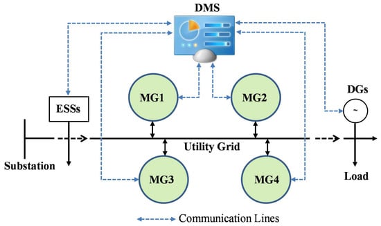
Figure 1.
Modern distribution grids with networked microgrids, DGs and ESSs.
3. Centralized Energy Management
As a base for comparison, a centralized optimization model for cooperative networked microgrids operation is formulated first. The objective function, as shown in (1), is targeting to minimize the total operating cost of the utility grid, meanwhile optimizing the network operational objectives, including bus voltage deviations, exchanged reactive power at the substation and network power loss. The total operating cost includes the operating cost of microgrids and utility directly interfaced devices. The operating cost of a microgrid, as shown in (2), includes piecewise linear DG operating cost, DG startup cost, ESS degradation cost, and load curtailment cost. Similarly, the operating cost of utility directly interfaced devices, as shown in (3), includes piecewise linear DG operating cost, DG startup cost, ESS degradation cost, load curtailment cost, and energy exchanging cost/benefit at distribution substation when grid-connected. The network operational objectives include total bus voltage deviations, total power loss of distribution network and total exchanged reactive power at the substation, which are shown in (4)–(6), respectively. Note that the network power loss is approximated as (5) based on linear DistFlow, which simply assumes p.u. [41]. A single objective is formulated through weighted summation as in (1), where , , and are corresponding weighting coefficients. The weighting coefficients could be simply determined based on the preferences of utility grid operators. Advanced methods, e.g., analytical hierarchy process (AHP) [42], could also be used to generate weighting coefficients for multi-objective optimization [43].
The objective function is subject to the follow constraints:
The operating costs of DGs are approximated using piecewise linearization. The power output of a DG equals its minimum power if committed plus the power scheduled in all blocks as enforced by (7). The power of each block is limited by (8). In addition, the output of a DG is constrained by its capacity and the commitment status as in (9). The DG power factor is guaranteed as in (10). The capacity limit of a DG is ensured in (11).
The maximum charging and discharging power of an ESS are limited by (12) and (13), separately. An ESS can only be charged or discharged at each moment, enforced by (14). The state of charge (SOC) of an ESS changes with the battery charging/discharging as represented in (15). The upper and lower limits of SOC are guaranteed by (16). The apparent power limit of the ESS converter is enforced by (17).
For each controllable load, the maximum percentage of load shedding is represented in (18). Depending on the power factor of the controllable load, the reactive power is shed accordingly, as represented in (19).
For each microgrid, the real and reactive power balance are guaranteed by (20) and (21), separately. The real power limit at PCC is limited by (22). The apparent power limit of PCC is ensured by (23).
The linear DistFlow is employed to model the network power flow constraints, as represented in (24)–(28) [44,45]. The voltage change between two adjacent buses connected by a feeder is shown as in (24). Equations (25) and (26) guarantee the real and reactive power are balanced at each bus. , and are incidence matrices for distribution substations, distribution feeders and microgrids. Likewise, , and are incidence matrices for utility grid directly interfaced DERs and loads. The bus voltage constraint is represented by (27). The feeder capacity is guaranteed as in (28).
In both grid-connected and islanded mode, the distribution substation is taken as a slack bus with fixed voltage magnitude as represented in (29). The exchanged power at the distribution substation is limited by (30). The capacity limits of distribution transformers are enforced by (31).
The centralized energy management for networked microgrids could be represented as a mixed integer quadratically constrained program (MIQCP) model and solved by commercial MIQCP solvers. To convert nonlinear items into mixed-integer linear (MIL) format, the DG startup cost in (1) could be formulated in MIL format according to [46]. Likewise, the absolute function and logic items in (1) are recast into MIL format according to [43].
4. Distributed Energy Management
Note that only (25) and (26) are complicating constraints, which involve variables of both the utility network level and microgrid level. Given this separable structure, the centralized model presented above is decomposed into parallel subproblems of DMS and MCs using the ADMM algorithm [47]. Depending on the attribution of the jurisdiction of utility directly interfaced DERs and controllable loads, their scheduling could be either included in the DMS subproblem or formulated as an independent subproblems similar to MC subproblem. If the utility directly interfaced DERs and controllable loads are under the jurisdiction of DMS, the scheduling of these DERs and controllable loads are simply included in the DMS subproblem. If the utility directly interfaced DERs and controllable loads are under the jurisdiction of a third party, the scheduling of these DERs and controllable loads are formulated as subproblems parallel to MC subproblems. For simplicity, the first situation is used in this work. Nevertheless, the proposed model could be easily adapted to the second situation.
Given the initial generation-load mismatch (i.e., primal residual) calculated according to (32) and the initial price signal of each bus, the DMS subproblem and MC subproblems are solved in parallel. Each MC solves an MC subproblem to schedule their internal DERs and loads and update the PCC power accordingly. Meanwhile, the DMS solves the DMS subproblem to schedule the power imported/exported at the distribution substation bus and utility directly controlled DERs and loads.
Specifically, for microgrid m connected at bus n, the MCs of microgrid m solves its MC subproblem as following:
s.t. (7)–(23).
After that, DMS or a third party without conflict of interest updates the primal residual and dual residual (i.e., bus price signal) according to (32) and (35), correspondingly.
The iteration stops when both primal residual and dual residual are converged [47]. Due to the fact that the dual residual is an affine function of primal residual with a small slope according to (35), the convergence criterion of the proposed distributed method should be the primal residual converges to zero or a neglectable small number. In practice, this means the generation and load are well matched under the agreed price for all buses.
The proposed distributed method is described in detail as shown in Algorithm 1. It is worth mentioning that the proposed distributed method preserves the privacy and autonomy of internal DERs and loads for each microgrid since the only information needed by the DMS from each MC is the power at its PCC. This is especially important for emerging DER and load aggregators.
Without loss of generality, only real power is assumed transactive in this work. Nevertheless, reactive power could also be traded between DMS and microgrids as well.
| Algorithm 1 Proposed Distributed Energy Management for Networked Microgrids |
| initialization . DMS initializes primal residual and dual residual , then sends them to MCs at corresponding buses. repeat .
|
5. Case Study Using DECC 6-Bus Test System
5.1. Test System
The proposed distributed method is tested using a modified Oak Ridge National Laboratory (ORNL) Distributed Energy Control and Communication (DECC) networked microgrids test system, as presented in Figure 2. The test system includes 6 buses with bus 1 as a substation bus. Three microgrids are interfaced at bus 3, 4 and 5, respectively. Each microgrid includes DERs and loads. In addition, several utility directly interfaced DERs and controllable loads are connected at bus 2 and 6.
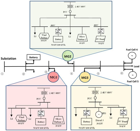
Figure 2.
Modified ORNL DECC networked microgrids system.
The resistance and reactance of distribution feeders are shown in Table 1.

Table 1.
Parameters of feeders.
The parameters of dispatchable DGs in microgrids and the ones directly interfaced with the utility grid are given in Table 2 [15]. For each dispatchable DG, its generation cost is assumed piecewise linear with three pieces.

Table 2.
Dispatchable DGs parameters.
For simplicity, the three batteries in microgrids and the utility grid directly interfaced battery on bus 2 are assumed same. Its parameters are given in Table 3.

Table 3.
Parameters of batteries.
The wind and PV power outputs are the same as [17]. The microgrid loads and total utility directly interfaced loads are forecasted as in Figure 3. The power factor of all loads is assumed 0.9. The maximum percentage of load shedding is assumed 80% with cost set as 1 $/kWh.
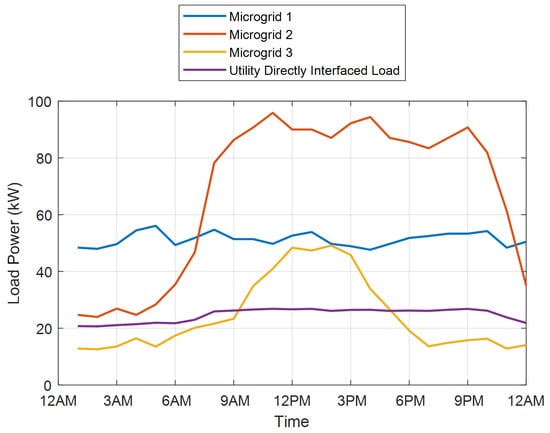
Figure 3.
System Loads.
In grid-connected mode, power could be imported or exported at the distribution substation bus according to the utility rate, as given in Table 4. The exchanged power at PCC of any microgrid is limited to 150 kW.

Table 4.
Utility rate.
The daily operation of the networked microgrids test system is simulated with 1-h time intervals. The distribution substation is taken as a slack bus with a fixed voltage magnitude set as 1.01 p.u. The bus voltage is limited to p.u., but preferred in p.u., beyond which is allowed, but penalized as voltage deviations. The penalty factor is assumed 0.1.
Both centralized and proposed distributed optimization are MIQCP problems. The branch and bound (B&B) algorithm provide an efficient way to solve MIQCP problems [48]. The B&B algorithm solves MIQCP problems by breaking them down into smaller subproblems and using a bounding function to eliminate subproblems that cannot contain the optimal solution until all subproblems generated in the search space are examined. The B&B algorithm has been implemented in CPLEX Mixed-Integer Optimizer. All optimization models in the case studies are formulated in MATLAB and solved using IBM ILOG CPLEX Optimization Studio 12.6 [49]. The solution time of each iteration in the proposed distributed optimization is normally less than 10 s.
5.2. Comparing Objective Values and Costs of Various Cases
Using both centralized and proposed distributed methods, various objective values and costs are obtained and compared in Table 5. Without loss of generality, , , and are used in the simulation. During grid-connected operation, power imports/exports are assumed available at the distribution substation bus based on given utility rates as in Table 4. While during islanded operation, the power imports/exports at the distribution substation are zero. Therefore, the total operating cost of DMS is reduced significantly in islanded mode.

Table 5.
Comparison of various objective values and costs in various cases.
Comparing the calculated various objective values and costs between centralized optimization and the proposed distributed optimization, the total objective value of the proposed distributed method has been increased by 0.91% and 0.58% in grid-connected and islanded mode, separately. The slight differences are due to the nonconvexity of the problem. Besides, comparing network operation objectives, i.e., total voltage deviations, network power loss and reactive power exchanged at the distribution substation, the values calculated by the centralized method and proposed distributed method are almost the same. Therefore, the soundness of the proposed distributed method is validated.
5.3. Convergence of Proposed Method
The convergence of the ADMM algorithm requires both primal residual and dual residual to be converged [47]. Specifically to our problem, the dual residual converges only when the primal residual converges to zero since the dual residual is an affine function of primal residual with very small slope according to Equation (35). Thus, the convergence criterion of the proposed distributed method is that the primal residual , i.e., generation-load mismatches of all buses, are neglectable. It also means that the power balance is reached at all buses under the negotiated price. As the iteration goes, the obtained generation-load mismatches of all buses in grid-connected and islanded modes are presented in Figure 4a,b, separately. Generally, the proposed ADMM-based distributed method converges fast at the beginning, but slowly later when the primal residual is getting smaller. For this reason, the convergence criterion in the simulation is set as kW.
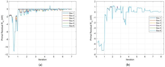
Figure 4.
The generation-load mismatches at each bus along iterations. (a) Grid-Connected. (b) Islanded.
5.4. Solutions of Proposed Method
More detailed solution results of proposed distributed energy management for cooperative networked microgrids operation are presented in this subsection. The results are compared with those solved by the centralized method as further validation. In addition, the calculated nodal prices by the distributed method are presented. The influencing factors of nodal prices are analyzed as well.
5.4.1. Grid-Connected Mode
The PCC power and bus voltage profiles calculated by the proposed distributed method are presented and compared with those calculated by the centralized method, as shown in Figure 5 and Figure 6. Except for small differences at the beginning of the day (e.g., Hour 1–3 a.m.) and during the noon (e.g., Hour 1–2 p.m.), the PCC and substation power are generally the same for the centralized and proposed distributed method, as can be seen in Figure 5. Likewise, the calculated bus voltage profiles by the centralized and proposed distributed methods are nearly the same. This further validates the accuracy of the proposed distributed method.
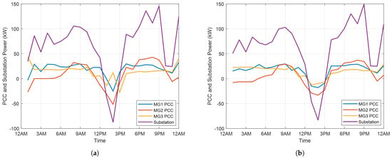
Figure 5.
PCC and substation power in grid-connected mode. (a) Centralized Method. (b) Distributed Method.
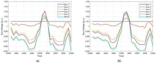
Figure 6.
Bus voltage profiles in grid-connected mode. (a) Centralized Method. (b) Distributed Method.
All bus voltage profiles, except the substation bus (i.e., bus 1), share the same trend which jumps high at noon due to the surging of PV outputs, as can be seen in Figure 6. However, bus 6 has the most volatile voltage profile compared with other buses. This is because bus 6 is at the end of the feeder.
The converged price signals of different buses as well as the utility rate are compared in Figure 7. Generally, these price curves follow the trend of utility rate at the distribution substation bus, and the price differences between buses are small. This is mainly due to two facts. First, the distribution substation bus, i.e., the slack bus, works as the marginal unit of the system most of the time. Second, the total objective value is mainly dominated by operating costs. Nevertheless, it can be clearly observed that the bus prices are affected by the operational objectives, i.e., voltage deviations, network power loss and reactive power at the distribution substation.
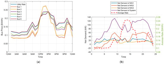
Figure 7.
Calculated bus prices and system net demands in grid-connected mode. (a) Bus Price. (b) System Net Demand.
Basically, the price of a bus is the marginal cost of delivering an increment of energy to the specific bus. In our model, the marginal cost includes marginal operating cost, marginal power loss, marginal voltage deviation and marginal reactive power at the substation. For most time intervals in the day, except 12 p.m.–3 p.m., the system imports power from the utility grid and the power flows from bus 1 to bus 6 as can be seen in Figure 5, the marginal operating cost and the marginal reactive power at the substation are generally the same for all buses. However, bus 6 has the largest marginal power loss since it has the largest resistance to the power origin (i.e., bus 1). Meanwhile, bus 6 also has the largest marginal voltage deviation since an increment of energy at bus 6 will cause the worst voltage deviation of the network. Thus, bus 6 has the highest price and bus 1 has the lowest price (almost the same as the utility rate) during these time intervals.
From 12 p.m. to 3 p.m., the direction of power flow is reversed due to the surging of PV outputs with power flowing from bus 4 to bus 1. Under this situation, the marginal operating cost and the marginal reactive power at the substation are still the same for all buses. However, bus 1 has the largest marginal power loss since it has the largest resistance to the power origin (i.e., bus 4). As to the marginal voltage deviation, the marginal voltage deviation of bus 4 is zero since it is the power origin. With constant voltage at bus 1, an increment of energy at bus 1 will cause worse overvoltage at bus 4. Thus, the marginal voltage deviation at bus 1 is positive. As to bus 6, an increment of energy at bus 6 will reduce the overvoltage at bus 4, thus the marginal voltage deviation at bus 6 is negative. Under this situation, bus 6 has the lowest price and bus 1 has the highest price. The prices of bus 3 and 4 are in the middle, as shown in Figure 7a. To summarize, the operating costs dominate the nodal prices, but the network operational objectives have unneglectable effects on nodal prices.
It should be noted that the proposed distributed energy management provides all participants with opportunities of contributing to improving network operational objectives while still satisfying each participant’s constraints and preserving their privacy and goals. In this simulation, supplying power to utility between 12 p.m. and 3 p.m. could benefit both utility and DG/microgrids owners. From this point of view, the results in Figure 7a make a lot of sense. Nevertheless, other utilities might want to promote local consumption of DG generation and avoid backward power feeding to the distribution substation. In those situations, the proposed distributed optimization could also help achieve this goal by simply adding a constraint to enforce nonnegative.
For each microgrid as well as the whole system, the net demand (i.e., total load minus total renewable generation) are calculated and compared with the average nodal energy rate in Figure 7b. As can be seen, the average nodal energy rate is not related to either system or microgrid net demand but largely follows the utility rate profile.
To estimate the error of linear DistFlow caused by the assumption of p.u., when the voltage is at the lower bound, i.e., p.u., the assumption of p.u., will cause an error of power loss around 10% (). In our simulation, the weighting factor of power loss is set as , as stated earlier. The calculated power loss is around 50 kWh, while the objective function is around 250 (according to Table 5). Thus, with a 10% error in power loss, the error of objective value is around 2%. Considering the situation of voltage at the lower bound is not regular (less than 1 quarter of the whole period, according to Figure 6), the error of the objective value should be less than 0.5%, which is acceptable in our case.
In general, the generation cost dominates the objective function. Thus, the assumption of p.u. should not cause a large error in the objective value. However, if the power loss of the network dominates the objective by setting a large weighting factor , the assumption of p.u. might cause a large error of the objective value when the voltage is constantly close to the lower bound, i.e., 0.95 p.u. Under this situation, the original DistFlow model should be used. The network power flow will be modeled as a second-order cone.
5.4.2. Islanded Mode
In islanded mode, the PCC power and bus voltage profiles calculated by the proposed distributed method are presented and compared with those calculated by the centralized method, as shown in Figure 8 and Figure 9. Generally, the PCC and substation power calculated by centralized and proposed distributed method is close to each other, as can be seen in Figure 8. Likewise, the calculated bus voltage profiles by the centralized and proposed distributed method are nearly the same as shown in Figure 9. The accuracy of the proposed distributed method in islanded mode is validated.
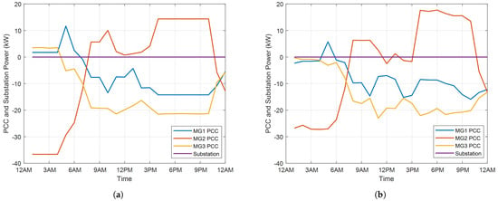
Figure 8.
PCC and substation power in islanded mode. (a) Centralized Method. (b) Distributed Method.
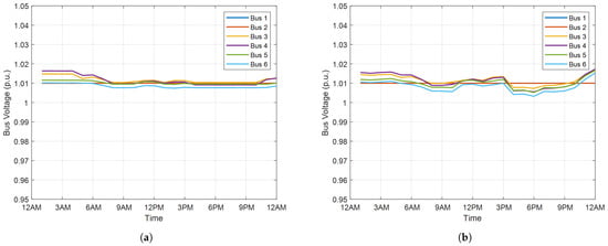
Figure 9.
Bus voltage profiles in islanded mode. (a) Centralized Method. (b) Distributed Method.
Compared with grid-connected mode, the voltage profiles in islanded mode are much better, as shown in Figure 9b. The reason is that significant power is imported from the substation slack bus and transmitted through the feeders in grid-connected mode due to relatively low cost. While in the islanded model, all loads are satisfied by local DERs. As a result, the power flow on the feeders has been significantly reduced, as reflected by the total network power loss in Table 5. Therefore, the voltage profiles are significantly improved in islanded mode.
The calculated bus prices are presented in Figure 10. Comparing the price between different buses, the converged price signals are almost the same for all buses, as shown in Figure 10a. This is because there is no reactive power exchange at the substation and the bus voltage deviations are zero, as can be seen in Figure 9. In addition, the network power loss is very small as shown in Table 5. Thus, the differences in marginal cost between buses are very little.
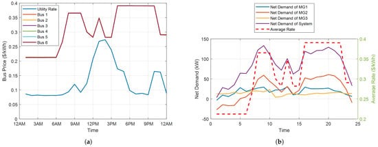
Figure 10.
Calculated bus prices and system net demands in islanded mode. (a) Bus Price. (b) System Net Demand.
The net demand of microgrids and the net demand of the whole system are calculated and compared with the average nodal energy rate in Figure 10b. As can be seen, the average nodal energy rate is closely coupled with the net demand of the system.
6. Practical Case Study and HIL Validation Using the Adjuntas 2-Microgrid System in Puerto Rico
A case study of the Adjuntas 2-microgrid system in Puerto Rico is presented in this section to further validate the proposed optimization strategy using HIL testing. The applicability of the proposed strategy is validated through HIL testing. In addition, the resiliency benefits of interconnecting and coordinating adjacent microgrids into networked microgrids are demonstrated as well.
6.1. System Introduction
The two microgrids were deployed in Adjuntas, Puerto Rico, as shown in Figure 11a. The two microgrids, i.e., the north-east microgrid and the west microgrid are physically co-located at the same plaza. These two microgrids serve 15 businesses as listed. The north-east microgrid and the west microgrid are interconnected through overhead lines to form a networked microgrid system. It is important to note that Figure 11a shows the original design and the participating businesses as of 2019, and the microgrids deployed eventually might be different from the ones presented in this paper.

Figure 11.
Adjuntas networked microgrids. (a) 3D renderings of two microgrids in Adjuntas, Puerto Rico. (b) Adjuntas networked microgrids diagram.
The single-line diagram of the two microgrids together with the power rating and generation mix are shown in Figure 11b. The north-east microgrid has a 442 kWh battery pack and 98 kW PV panels. The west microgrid includes a 663 kWh battery pack and 76 kW PV panels. The minimum and maximum SOC of both batteries are set as 25% and 95%, separately.
For each microgrid, the overall loads are aggregated into two loads: a critical load and a non-critical load. The one-week aggregated load profiles of both microgrids with 15-min time resolution are shown in Figure 12. The solar irradiance of the same week is also shown in Figure 12.
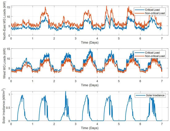
Figure 12.
Critical and non-critical loads and solar irradiance.
6.2. Case Study Results
Both the north-east microgrid and the west microgrid have PV panels as the sole generation source and batteries as energy storage. The grid-connected mode is fairly easy to converge under this system configuration since the distribution substation is taken as the slack bus to absorb any redundant PV generation or meet any excess load, while the convergence of islanded mode is more challenging since PV spillage or load shedding are necessary under certain conditions. For this reason, only the results of islanded mode are presented here. The simulation is conducted for a week. In order to test the proposed method under various possible conditions, three cases are studied.
- Case 1: Networked microgrids in islanded mode.
- Case 2: Networked microgrids in islanded mode, but the available PV panels in the north-east microgrid are reduced by 50% due to extreme weather.
- Case 3: Networked microgrids in islanded mode, but the available PV panels in the west microgrid are reduced by 50% due to extreme weather.
The optimization results calculated by both centralized and the proposed distributed methods for Case 1 are shown in Figure 13. The SOC of the batteries, PV utilization rate and load served rate are compared. As can be seen, the results of the proposed distributed method are almost the same as those of the centralized method. Thus, the accuracy of the proposed centralized method is validated.
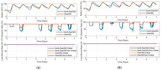
Figure 13.
Optimization results of Adjuntas 2-microgrid system in Case 1. (a) Centralized Method. (b) Distributed Method.
Case 2 and Case 3 simulate the networked microgrids with degraded PV due to extreme weather event. The optimization results calculated by both centralized and the proposed distributed methods for Case 2 and Case 3 are shown in Figure 14 and Figure 15, separately. The SOC of the batteries, PV utilization rate and load served rate are compared. Likewise, the results of the proposed distributed method are almost the same as those of the centralized method.
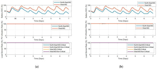
Figure 14.
Optimization results of Adjuntas 2-microgrid system in Case 2. (a) Centralized Method. (b) Distributed Method.
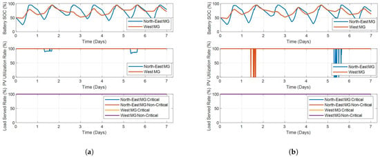
Figure 15.
Optimization results of Adjuntas 2-microgrid system in Case 3. (a) Centralized Method. (b) Distributed Method.
For the three cases, the energy price at each bus is calculated and compared in Figure 16. The PV generation cost is zero. The energy price of the system are mainly determined by the battery degradation cost caused by charging/discharging cost (set as 0.005 $/kW), penalty cost of PV spillage (set as 0.025 $/kW), and cost of load shedding (set as 0.5 $/kW for critical load and 0.3 $/kW for non-critical load). Due to the fact the feeder connecting the north-east microgrid and the west microgrid is very short, the voltage deviations and loss are relatively small. Therefore, the calculated price curves at different buses are very close.

Figure 16.
Calculated bus prices of Adjuntas 2-microgrid system in various cases. (a) Case 1. (b) Case 2. (c) Case 3.
Generally, the bus energy price is positive when the battery is discharging, but negative when the battery is charging. The absolute value of bus price is very small (around 0.005 $/kW) when there is neither load shedding nor PV spillage. When the system is spilling PV power, the bus energy price is around −0.03 $/kW.
6.3. HIL Testing
The solution process of the proposed distributed method is validated on a hardware-in-the-loop (HIL) test bed. To implement the hardware testing, the Adjuntas 2-microgrid system in Puerto Rico is modeled in Typhoon by the schematic in Figure 17. Each microgrid consists of a PV inverter, an energy storage device (both modeled as a two-level three-phase inverter with inductive and capacitive LCL filter), PCC switch, dynamic PQ loads, and inductive-resistive (LR) line sections.
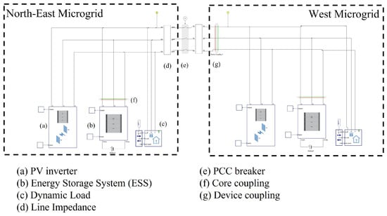
Figure 17.
The Typhoon model of the Adjuntas 2-microgrid system.
The hardware setup of the HIL test bed of the Adjuntas 2-microgrid system in Puerto Rico is shown in Figure 18. It is composed of two paralleled Typhoon HIL 604 and SEL 651R reclosers. The reclosers are in the loop with the real-time simulator and are included to provide an approximation of the real system. The Typhoon 604 is connected to the SEL reclosers through a Typhoon HIL Connect, which provides analog and digital signals to the SEL-651R relays. These signals represent the analog voltage and current inputs to the relays, the binary outputs from the relay for opening and closing each recloser switch inside the model, and a binary status input to the relay to indicate the state of the recloser switch only.
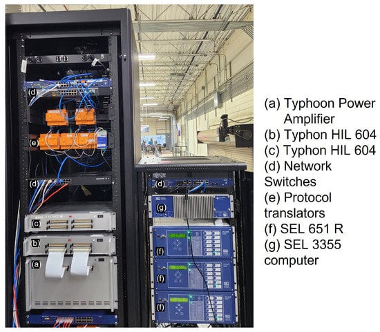
Figure 18.
The HIL test bed of Adjuntas 2-microgrid system.
The optimization runs on a separate computer that communicates with the real-time simulator through Modbus. The python package pyModbusTCP 0.2.0 was used to establish the Modbus master on the computer. The real-time simulator uses a proprietary Modbus master to send and receive data from external sources.
To compare the simulation results and hardware test results, the SOC of batteries, PV utilization rates and load served rates in different cases are plotted and compared in Figure 19. It is observed that the SOC of batteries, PV utilization rates and load served rates from numerical simulation and HIL testing match closely in all cases. Thus, the applicability of the proposed distributed optimization strategy is validated through HIL testing.
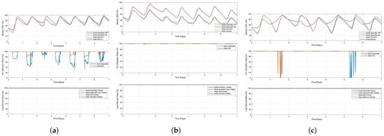
Figure 19.
HIL testing results of the Adjuntas 2-microgrid system in various cases. (a) Case 1. (b) Case 2. (c) Case 3.
To further demonstrate the resiliency benefits of interconnecting and coordinating adjacent microgrids into networked microgrids, three additional cases of independent microgrids without interconnection and coordination are studied.
- Case 4: Independent microgrids in islanded mode.
- Case 5: Independent microgrids in islanded mode, but the available PV panels in the north-east microgrid is reduced by 50% due to extreme weather.
- Case 6: Independent microgrids in islanded mode, but the available PV panels in the west microgrid is reduced by 50% due to extreme weather.
The optimization results calculated for Cases 4–6 are shown in Figure 20. The SOC of batteries, PV utilization rates and load served rates in different cases are plotted. Comparing with the results of networked operation Cases 1–3, it is observed that the load served rates under extreme weather events are significantly improved by interconnecting and coordinating adjacent microgrids into networked microgrids, i.e., the load shedding could be significantly reduced or avoided by networking microgrids. Therefore, the resiliency benefits of interconnecting and coordinating adjacent microgrids into networked microgrids under extreme weather events are validated.
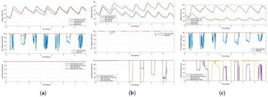
Figure 20.
HIL testing results of the Adjuntas 2-microgrid system in independent operation cases. (a) Case 4. (b) Case 5. (c) Case 6.
While the current focus of this paper is to enable all participants to contribute to improving network operational objectives (such as bus voltage regulation, power factor improvements and network power loss reduction), the proposed distributed optimization model can be extended to include carbon emission costs of DG generation and energy purchased from distribution substation into the objective function, so as to reduce the total carbon emission of the whole system.
7. Conclusions
A distributed energy management for the coordination of networked microgrids, utility directly interfaced DERs and controllable loads is proposed in this paper. The objectives include minimizing total system operating costs as well as optimizing network operational objectives, e.g., bus voltage deviations, power factor improvements and network power loss. Considering various ownership and privacy requirements of microgrids, utility directly interfaced DERs and controllable loads, the proposed distributed method provides all participants with opportunities of contributing to improving network operational objectives while still satisfying each participant’s constraints and preserving their privacy and goals. The proposed method is validated using a practical two-microgrid system located in Adjuntas, Puerto Rico through HIL testing.
Compared with centralized optimization-based methods, the proposed distributed method is more scalable and computationally efficient since the solution process of subproblems could be parallel. In addition, the proposed distributed method does not require any information behind the PCC, thus preserving the privacy and autonomy of microgrids and reducing communication needs. Nevertheless, the success of the proposed distributed method still requires a two-way communication system. Due to the nonconvexity of the problem, the proposed distributed method cannot guarantee the global optimum, either.
In a real implementation, the efficiency of the calculated solution might be affected by uncertainties of renewable generation or the unavailability of DERs. In grid-connected mode, the power mismatch caused by uncertainties will be mitigated by the distribution substation, which could increase the total operating cost. In islanded mode, significant power mismatch might jeopardize the security of the whole system. Furthermore, the proposed algorithm assumes a radial distribution network. The effectiveness of the proposed algorithm in meshed distribution networks should be further investigated.
Robust distributed methods considering the uncertainties of renewable generation as well as the unavailability of DERs will be investigated in future work. In addition, the proposed method will be tested on more practical distribution networks with meshed topology.
Author Contributions
G.L. carried out the main research tasks and wrote the full manuscript. M.F.F., T.B.O. and A.S. contributed to the development of the proposed methodology and the literature review. M.O. and Y.C. provided important suggestions on writing of the paper. M.F.F. performed the HIL testing. All authors have read and agreed to the published version of the manuscript.
Funding
This research is based upon work supported by the U.S. Department of Energys Office of Energy Efficiency and Renewable Energy (EERE) under the Solar Energy Technologies Office (SETO) Award Number DE-EE0002243-2144.
Institutional Review Board Statement
Not applicable for studies not involving humans or animals.
Informed Consent Statement
Not applicable.
Data Availability Statement
No new data were created or analyzed in this study. Data sharing is not applicable to this article.
Acknowledgments
This manuscript has been authored by UT-Battelle, LLC under Contract No. DE-AC05-00OR22725 with the U.S. Department of Energy. The United States Government retains and the publisher, by accepting the article for publication, acknowledges that the United States Government retains a non-exclusive, paid-up, irrevocable, world-wide license to publish or reproduce the published form of this manuscript, or allow others to do so, for United States Government purposes. The Department of Energy will provide public access to these results of federally sponsored research in accordance with the DOE Public Access Plan (http://energy.gov/downloads/doe-public-access-plan (accessed on 1 March 2023)).
Conflicts of Interest
The authors declare no conflict of interest.
Nomenclature
A symbol with on the upper right corner indicates its value of k-th iteration. A symbol with m on the low right corner indicates it belongs to microgrid m, otherwise it is utility directly interfaced. The bold symbols represent corresponding vectors/matrices.
| Indices | |
| m | Index of microgrids, running from 1 to . |
| l | Index of loads in microgrid m/distribution network, running from 1 to /. |
| g | Index of distributed generators (DGs) in microgrid m/distribution network, running |
| from 1 to /. | |
| b | Index of batteries in microgrid m/distribution network, running from 1 to /. |
| v | Index of PV in microgrid m, running from 1 to . |
| w | Index of wind turbines in microgrid m, running from 1 to . |
| n | Index of buses, running from 1 to . |
| f | Index of feeders, running from 1 to . |
| t | Index of time periods, running from 1 to . |
| k | Index of iterations. |
| i | Index of energy blocks offered by DGs, running from 1 to . |
| Variables | |
| Binary Variables | |
| Binary indicator for unit g on/off status during period t. | |
| Binary indicator for battery b charging/discharging status during period t. | |
| Continuous Variables | |
| Scheduled power from the i-th block of energy offer by DG g in microgrid | |
| m during period t. | |
| Real and Reactive power injection of DG g in microgrid m during period t. | |
| Charging/discharging power of battery b in microgrid m during period t. | |
| Reactive power output of battery b in microgrid m during period t. | |
| State of charge (SOC) of battery b in microgrid m during period t. | |
| Output of wind turbine w in microgrid m during period t. | |
| Output of PV panel v in microgrid m during period t. | |
| Real/Reactive power shedding of load l in microgrid m during period t. | |
| Real/Reactive power injection at point of common coupling (PCC) of | |
| microgrid m during period t. | |
| Real and reactive power flow in feeder f during period t. | |
| Voltage magnitude of bus n during period t. | |
| Voltage magnitude of substation bus during period t. | |
| Real/Reactive injection at the substation slack bus during period t. | |
| Generation-load mismatch at bus n during period t. | |
| Lagrange multiplier of power balance equation at bus n during period t. | |
| Real power matrices of DGs, batteries and loads that directly interfaced | |
| with distribution network. | |
| Reactive power matrices of DGs, batteries and loads that directly | |
| interfaced with distribution network. | |
| Startup cost of DG g in microgrid m during period t. | |
| Total operating cost of microgrid m. | |
| Total operating cost of utility directly interfaced devices. | |
| Total bus voltage deviations. | |
| Total power loss of distribution network. | |
| Total exchanged reactive power at substation. | |
| Constants | |
| Price of real/reactive power exchange at distribution substation | |
| bus during period t. | |
| Marginal cost of the i-th block of energy offer by DG g during | |
| period t. | |
| Battery b degradation cost. | |
| Load l curtailment cost. | |
| Maximum power limits from the i-th block of energy offer by DG | |
| g in microgrid m. | |
| Power limits of DG g of microgrid m. | |
| Maximum power exchange of microgrid m at PCC. | |
| Maximum power exchange at distribution substation bus. | |
| Charging/discharging power limits of battery b in microgrid m. | |
| SOC limits of battery b. | |
| Charging/discharging efficiency of battery b. | |
| Estimated real/reactive power of load l. | |
| Allow percentage of power shedding for load l. | |
| Operating Cost of DG g at minimum power output. | |
| Penalty factor of augmented Lagrange term. | |
| Duration of time intervals. | |
| Limits of preferred voltage range for buses. | |
| Minimum/maximum voltage limits for buses. | |
| Constant voltage magnitude of distribution substation bus. | |
| Apparent power limit of battery b, DG g and feeder f. | |
| Apparent power limit of microgrid m at PCC. | |
| Apparent power limit of distribution substation. | |
| Resistance and reactance of feeder from f. | |
| Power factor of load l. | |
| Power factor limit of DG g. | |
| Limit of generation-load mismatch for convergence. | |
| Weighting factors of the objectives. | |
| Incidence matrix for microgrids. | |
| Incidence matrix for distribution substation. | |
| Incidence matrix for feeders. | |
| Incidence matrix for DGs, batteries and loads that directly | |
| interfaced with distribution network. | |
References
- Cagnano, A.; De Tuglie, E.; Mancarella, P. Microgrids: Overview and guidelines for practical implementations and operation. Appl. Energy 2020, 258, 114039. [Google Scholar] [CrossRef]
- Khan, M.Z.; Mu, C.; Habib, S.; Alhosaini, W.; Ahmed, E.M. An Enhanced Distributed Voltage Regulation Scheme for Radial Feeder in Islanded Microgrid. Energies 2021, 14, 6092. [Google Scholar] [CrossRef]
- Park, B.; Zhang, Y.; Olama, M.; Kuruganti, T. Model-free control for frequency response support in microgrids utilizing wind turbines. Electr. Power Syst. Res. 2021, 194, 107080. [Google Scholar] [CrossRef]
- Liu, R.; Wang, S.; Liu, G.; Wen, S.; Zhang, J.; Ma, Y. An Improved Virtual Inertia Control Strategy for Low Voltage AC Microgrids with Hybrid Energy Storage Systems. Energies 2022, 15, 442. [Google Scholar] [CrossRef]
- Wang, Y.; Yi, A.; Rousis, O.; Strbac, G. On microgrids and resilience: A comprehensive review on modeling and operational strategies. Renew. Sustain. Energy Rev. 2020, 134, 110313. [Google Scholar] [CrossRef]
- Hirsch, A.; Parag, Y.; Guerrero, J. Microgrids: A review of technologies, key drivers, and outstanding issues. Renew. Sustain. Energy Rev. 2018, 90, 402–411. [Google Scholar] [CrossRef]
- Chen, B.; Wang, J.; Lu, X.; Chen, C.; Zhao, S. Networked Microgrids for Grid Resilience, Robustness, and Efficiency: A Review. IEEE Trans. Smart Grid 2021, 12, 18–32. [Google Scholar] [CrossRef]
- Zou, H.; Mao, S.; Wang, Y.; Zhang, F.; Chen, X.; Cheng, L. A Survey of Energy Management in Interconnected Multi-Microgrids. IEEE Access 2019, 7, 72158–72169. [Google Scholar] [CrossRef]
- Islam, M.; Yang, F.; Amin, M. Control and optimisation of networked microgrids: A review. IET Renew. Power Gener. 2021, 15, 1133–1148. [Google Scholar] [CrossRef]
- Xie, H.; Wang, W.; Wang, W.; Tian, L. Optimal Dispatching Strategy of Active Distribution Network for Promoting Local Consumption of Renewable Energy. Front. Energy Res. 2022, 10, 826141. [Google Scholar] [CrossRef]
- Liu, G.; Moorthy, R.S.; Choi, J.; Chinthavali, M.S. Linearised three-phase optimal power flow for coordinated optimisation of residential solid-state power substations. IET Energy Syst. Integr. 2021, 3, 344–354. [Google Scholar] [CrossRef]
- Hussain, A.; Bui, V.H.; Kim, H.M. A Resilient and Privacy—Preserving Energy Management Strategy for Networked Microgrids. IEEE Trans. Smart Grid 2018, 9, 2127–2139. [Google Scholar] [CrossRef]
- Huang, Y.; Ju, Y.; Ma, K.; Short, M.; Chen, T.; Zhang, R.; Lin, Y. Three-phase optimal power flow for networked microgrids based on semidefinite programming convex relaxation. Appl. Energy 2021, 305, 117771. [Google Scholar] [CrossRef]
- Haghifam, S.; Najafi-Ghalelou, A.; Zare, K.; Shafie-khah, M.; Arefi, A. Stochastic bi-level coordination of active distribution network and renewable-based microgrid considering eco-friendly compressed air energy storage system and intelligent parking lot. J. Clean. Prod. 2021, 278, 122808. [Google Scholar] [CrossRef]
- Liu, G.; Xu, Y.; Tomsovic, K. Bidding Strategy for Microgrid in Day-ahead Market based on Hybrid Stochastic/Robust Optimization. IEEE Trans. Smart Grid 2016, 7, 227–237. [Google Scholar] [CrossRef]
- Choobineh, M.; Mohagheghi, S. Robust Optimal Energy Pricing and Dispatch for a Multi-Microgrid Industrial Park Operating Based on Just-In-Time Strategy. IEEE Trans. Ind. Appl. 2019, 55, 3321–33330. [Google Scholar] [CrossRef]
- Liu, G.; Ollis, T.B.; Ferrari, M.F.; Sundararajan, A.; Tomsovic, K. Robust Scheduling of Networked Microgrids for Economics and Resilience Improvement. Energies 2022, 15, 2249. [Google Scholar] [CrossRef]
- Warner, J.D.; Masaud, T.M. Decentralized Peer-to-Peer Energy Trading Model for Networked Microgrids. In Proceedings of the 2021 IEEE Conference on Technologies for Sustainability (SusTech 2021), Irvine, CA, USA, 22–24 April 2021; pp. 1–6. [Google Scholar]
- Rahbar, K.; Chai, C.C.; Zhang, R. Energy cooperation optimization in microgrids with renewable energy integration. IEEE Trans. Smart Grid 2018, 9, 1482–1493. [Google Scholar] [CrossRef]
- Malekpour, A.R.; Pahwa, A. Stochastic networked microgrid energy management with correlated wind generators. IEEE Trans. Power Syst. 2017, 32, 3681–3693. [Google Scholar] [CrossRef]
- Liu, G.; Ollis, T.; Xiao, B.; Zhang, X.; Tomsovic, K. Distributed Energy management for Community Microgrids Considering Phase balancing and peak Shaving. IET Gener. Transm. Distrib. 2019, 13, 1612–1620. [Google Scholar] [CrossRef]
- Feng, C.; Wen, F.; Zhang, L.; Xu, C.; Salam, M.A.; You, S. Decentralized Energy Management of Networked Microgrid Based on Alternating-Direction Multiplier Method. Energies 2018, 11, 2555. [Google Scholar] [CrossRef]
- Zhou, X.; Ai, Q. An integrated two-level distributed dispatch for interconnected microgrids considering unit commitment and transmission loss. J. Renew. Sustain. Energy 2019, 11, 025504. [Google Scholar] [CrossRef]
- Liu, T.; Tan, X.; Sun, B.; Wu, Y.; Tsang, D.H.K. Energy management of cooperative microgrids: A distributed optimization approach. Int. J. Electr. Power Energy Syst. 2018, 96, 335–346. [Google Scholar] [CrossRef]
- Liu, G.; Jiang, T.; Ollis, T.; Zhang, X.; Tomsovic, K. Distributed energy management for community microgrids considering network operational constraints and building thermal dynamics. Appl. Energy 2019, 239, 83–95. [Google Scholar] [CrossRef]
- Mojica-Nava, E.; Rivera, S.; Quijano, N. Game-theoretic dispatch control in microgrids considering network losses and renewable distributed energy resources integration. IET Gener. Transm. Distrib. 2017, 11, 1583–1590. [Google Scholar] [CrossRef]
- Velasquez, M.A.; Torres-Perez, O.; Quijano, N.; Cadena, A. Hierarchical dispatch of multiple microgrids using nodal price: An approach from consensus and replicator dynamics. J. Mod. Power Syst. Clean Energy 2019, 7, 1573–1584. [Google Scholar] [CrossRef]
- Xu, Q.; Zhao, T.; Xu, Y.; Xu, Z.; Wang, P.; Blaabjerg, F. A Distributed and Robust Energy Management System for Networked Hybrid AC/DC Microgrids. IEEE Trans. Smart Grid 2020, 11, 3496–3508. [Google Scholar] [CrossRef]
- Nikmehr, N. Distributed robust operational optimization of networked microgrids embedded interconnected energy hubs. Energy 2020, 199, 117440. [Google Scholar] [CrossRef]
- Mohseni, S.; Pishvaee, M.; Dashti, R. Privacy-preserving energy trading management in networked microgrids via data-driven robust optimization assisted by machine learning. Sustain. Energy Grids Netw. 2023, 34, 101011. [Google Scholar] [CrossRef]
- Liu, Z.; Wang, L.; Ma, L. A Transactive Energy Framework for Coordinated Energy Management of Networked Microgrids with Distributionally Robust Optimization. IEEE Trans. Power Syst. 2020, 35, 395–404. [Google Scholar] [CrossRef]
- Ma, W.; Wang, J.; Gupta, V.; Chen, C. Distributed Energy Management for Networked Microgrids Using Online ADMM with Regret. IEEE Trans. Smart Grid 2018, 9, 847–856. [Google Scholar] [CrossRef]
- Nikmehr, N.; Bragin, M.A.; Zhang, P.; Luh, P.B. Computationally Distributed and Asynchronous Operational Optimization of Droop-Controlled Networked Microgrids. IEEE Open Access J. Power Energy 2022, 9, 265–277. [Google Scholar] [CrossRef]
- Tightiz, L.; Yoo, J. A Review on a Data-Driven Microgrid Management System Integrating an Active Distribution Network: Challenges, Issues, and New Trends. Energies 2022, 15, 8739. [Google Scholar] [CrossRef]
- Salehi, N.; Martinez-Garcia, H.; Velasco-Quesada, G. Networked Microgrid Energy Management Based on Supervised and Unsupervised Learning Clustering. Energies 2022, 15, 4915. [Google Scholar] [CrossRef]
- Zhang, Q.; Dehghanpour, K.; Wang, Z.; Huang, Q. A Learning-Based Power Management Method for Networked Microgrids Under Incomplete Information. IEEE Trans. Smart Grid 2020, 11, 1193–1204. [Google Scholar] [CrossRef]
- Fang, D.; Guan, X.; Peng, Y.; Chen, H.; Ohtsuki, T.; Han, Z. Distributed Deep Reinforcement Learning for Renewable Energy Accommodation Assessment with Communication Uncertainty in Internet of Energy. IEEE Internet Things J. 2021, 8, 8557–8569. [Google Scholar] [CrossRef]
- Chen, J.; Alnowibet, K.; Annuk, A.; Mohamed, M. An effective distributed approach based machine learning for energy negotiation in networked microgrids. Energy Strategy Rev. 2021, 38, 100760. [Google Scholar] [CrossRef]
- Hanifi, S.; Liu, X.; Lin, Z.; Lotfian, S. A Critical Review of Wind Power Forecasting Methods—Past, Present and Future. Energies 2020, 13, 3764. [Google Scholar] [CrossRef]
- Sundararajan, A.; Ollis, B. Regression and Generalized Additive Model to Enhance the Performance of Photovoltaic Power Ensemble Predictors. IEEE Access 2021, 9, 111899–111914. [Google Scholar] [CrossRef]
- Baran, M.E.; Wu, F.F. Network reconfiguration in distribution systems for loss reduction and load balancing. IEEE Trans. Power Deliv. 1989, 4, 1401–1407. [Google Scholar] [CrossRef]
- Saaty, T. Decision making—The analytic hierarchy and network processes (AHP/Anp). J. Syst. Sci. Syst. Eng. 2004, 13, 1–35. [Google Scholar] [CrossRef]
- Liu, G.; Ollis, T.; Xiao, B.; Zhang, X.; Tomsovic, K. Community Microgrid Scheduling Considering Network Operational Constraints and Building Thermal Dynamics. Energies 2018, 10, 1554. [Google Scholar] [CrossRef]
- Turitsyn, K.; Sulc, P.; Backhaus, S.; Chertkov, M. Distributed control of reactive power flow in a radial distribution circuit with high photovoltaic penetration. In Proceedings of the IEEE Power & Energy Society General Meeting, Minneapolis, MN, USA, 25–29 July 2010; pp. 1–6. [Google Scholar]
- Koessler, R.J. Dynamic simulation of static VAR compensators in distribution systems. IEEE Trans. Power Syst. 1992, 7, 1285–1291. [Google Scholar] [CrossRef]
- Ortega-Vazquez, M.A. Optimizing the Spinning Reserve Requirements. Ph.D. Thesis, School of Electrical and Electronic Engineering, University of Manchester, Manchester, UK, 2006; pp. 1–219. Available online: https://labs.ece.uw.edu/real/Library/Thesis/Miguel_ORTEGA-VAZQUEZ.pdf (accessed on 1 March 2023).
- Boyd, S.; Parikh, N.; Chu, E.; Peleato, B.; Eckstein, E. Distributed Optimization and Statistical Learning via the Alternating Direction Method of Multipliers. Found. Trends Mach. Learn. 2021, 3, 1–122. [Google Scholar] [CrossRef]
- Kleinert, T.; Labbe, M.; Ljubi, I.; Schimidt, M. A survey on mixed- integer programming techniques in bilevel optimization. EURO J. Comput. Optim. 2011, 9, 100007. [Google Scholar] [CrossRef]
- The ILOG CPLEX Website. 2022. Available online: http://www-01.ibm.com/software/commerce/optimization/cplexoptimizer/index.html (accessed on 21 December 2022).
Disclaimer/Publisher’s Note: The statements, opinions and data contained in all publications are solely those of the individual author(s) and contributor(s) and not of MDPI and/or the editor(s). MDPI and/or the editor(s) disclaim responsibility for any injury to people or property resulting from any ideas, methods, instructions or products referred to in the content. |
© 2023 by the authors. Licensee MDPI, Basel, Switzerland. This article is an open access article distributed under the terms and conditions of the Creative Commons Attribution (CC BY) license (https://creativecommons.org/licenses/by/4.0/).