Article

The Performance of a Thermal Protection System for the Accessories of a TBCC Engine

Key Laboratory of Thermal Management and Energy Utilization of Aviation Vehicles, Ministry of Industry and Information Technology, Nanjing University of Aeronautics and Astronautics, Nanjing 210016, China
*
Author to whom correspondence should be addressed.
Energies 2023, 16(6), 2713; https://doi.org/10.3390/en16062713
Submission received: 13 February 2023 / Revised: 8 March 2023 / Accepted: 10 March 2023 / Published: 14 March 2023
(This article belongs to the Special Issue Heat and Cold Storage for a Net-Zero Future)

Abstract

:
A theoretical model for describing the heat transfer characteristics of a turbine-based combined cycle (TBCC) engine cabin was established in Matlab/Simulink to quickly predict the thermal protection performance for engine accessories. The model’s effectiveness was verified by comparing the numerical results with the experimental data. The effects of different heat insulation layer thicknesses and fuel temperatures on the thermal protection performance are discussed; based on these effects, the heat insulation layer of 5 mm and fuel of 353 K were chosen to design the thermal protection cases. Nineteen different thermal protection cases were proposed and evaluated by using the model. Two representative accessories were chosen for the evaluation of the thermal protection performance of these cases. For accessory 1 with an internal heat source of 1000 W and internal fuel access, the thermal protection effect of adding a heat insulation layer and ventilation was the best, which decreased the accessory temperature by 43 K. For accessory 2 without an internal heat source, the thermal protection effect of adding a heat insulation layer to the casing and fuel cooling was the most ideal, which decreased the accessory temperature by 190 K. In addition, a comprehensive assessment was made to compare the performances of thermal protection cases.

1. Introduction

For hypersonic aircraft, high-speed flight makes the aerodynamic heating effect on the external surface more severe such that the outer skin has an extremely high temperature [1,2,3]. As the aircraft needs to perform more and more diverse tasks, its electromechanical system becomes increasingly complex, and its power increases significantly [4,5]. The accessory system of an aircraft is a variety of accessory devices that are used to ensure its safe and stable operation, which are generally installed near the casing and are affected by the radiation of the high-temperature casing. They also have a large internal heating power. This makes the working environment of the accessories very critical [6]. However, most of the accessories have strict operation temperature limitations, especially for the electronic components, which makes the integrated thermal management of the accessories essential [7]. As a typical propulsion system suitable for hypersonic aircraft, a turbine-based combined cycle (TBCC) engine has a diversified accessory system that works under complex operation conditions [8,9]. In general, the accessories of a TBCC engine are very significant to the flight safety of aircraft but must withstand a severe thermal environment. Therefore, it is imperative to study the thermal protection performance of accessories to ensure their normal operation.
Before taking thermal protection measurements, it is necessary to analyze the heat transfer characteristics of the accessories in the engine cabin. Liu et al. defined the concept of a thermal environment accurately and then studied the thermal environment of the element components in a high-speed aircraft ramjet’s engine compartment using engineering methods [10]. Meanwhile, Liu et al. numerically simulated the aerodynamic and thermodynamic performances of an engine cabin and its component accessories; the results showed that the radiation heat transfer on the accessories has a great influence on the temperature distribution [11]. Wang et al. analyzed the internal heat transfer law of an engine cabin and revealed that the heat transfer process of an engine casing wall to the skin in the engine compartment is a comprehensive heat transfer process. The casing wall of the engine transmits heat to the inner wall of the skin by means of heat radiation and convective heat transfer. Furthermore, there are heat radiation and convection heat transfer processes between the outer wall of the skin and the atmospheric environment [12]. During the study of heat transfer characteristics, it is essential to take thermal protection measures to reduce the radiation heat from the casing to the accessories and take the heat in the accessories away. According to the existing thermal protection system scheme, the thermal protection system is divided into three categories according to the heat transfer mode, namely, passive, semi-active and active thermal protection scheme. In passive thermal protection, flexible fiber insulation felt is a common passive insulation material; it has the advantages of excellent heat insulation performance, lightweight, easy to bend and convenient to install. Moreover, phase change materials can also be used in passive thermal protection, which uses its own heat storage properties to absorb and store heat in the structure. Xue et al. studied the temperature resistance, elastic properties and heat insulation properties of flexible fiber insulation felt and showed that the flexible insulation felt has excellent heat insulation ability [13]. Lin et al. designed an expanded graphite–special paraffin composite phase change heat sink for the newly developed high-heat consumption module and the heat dissipation performance was shown to meet the requirements via simulation and comparison [14]. A convection cooling structure is one method of active thermal protection, which is designed as a channel or pipeline so that a cooling medium is allowed to flow in these channels, where heat is carried away by convection heat transfer. Albeirutty et al. conducted a numerical study on the heat transfer of gas turbines under different working conditions with air cooling [15]. Eric et al. developed tools and procedures for the numerical dynamic system modeling of a TBCC propulsion system, including thermal management systems for low-speed and high-speed flow paths [16]. Herschel et al. established an experimental test bed that was representative of an aircraft fuel thermal management system to facilitate the verification and evaluation of thermal management strategies [17]. George et al. designed a flexible fuel system topology, adding a recirculation tank based on the traditional fuel heat management system for the temporary storage of hot reflux fuel [18]. Jiang et al. studied the material selection and thermal structure design of typical passive thermal protection components of engines, such as inlet lip and leading-edge fuel injection support; developed the thermal structure calculation and evaluation method of active cooling combustors; and applied the tested thermal analysis program to the material configuration of active cooling combustors [19].
The above work on the engine compartment’s heating environment analysis and the study of thermal protection was generally focused on a single component using three-dimensional simulation or experimental research [20,21]. In the early stage of aircraft design, rapid evaluation of multiple cases within a short period is crucial for aircraft design and optimization [22]. However, fast system simulation studies of combined thermal protections for the accessories in the engine cabin are scarce. Therefore, this study aimed to establish a rapid computational model to evaluate the performance of different thermal protection cases for typical TBCC engine accessories. Simulink was chosen as the modeling environment due to its advantages of wide adaptability, clear structure, precise simulation and high efficiency. This modeling tool is not only expedient for modeling but is also convenient for modifying the system for new conditions and is very efficient regarding simulation calculations, and thus, it is widely used. Brian et al. proposed a general co-simulation method based on Matlab/Simulink, which supports multi-mode simulation of distributed models using an integrated architecture [23]. Yang et al. established a simulation platform of the fuel system of a certain type of aircraft in the Simulink environment, analyzed its working principle for different working conditions and designed the working mode of each subsystem [24]. Fadel et al. dealt with the motion control of an aircraft-integrated electro-hydraulic servo-actuator (ISA) via the development of a detailed nonlinear mathematical model and a computer simulation program using the Matlab/Simulink package [25]. The model established in Simulink in this study can be used to conduct lots of design calculations to optimize the design of the whole in-cabin accessory thermal management system of a TBCC engine in its early stage.

2. Simulation Model and Method

2.1. Physical Model and Mathematical Model

The schematic diagram of the physical model in the TBCC engine cabin is shown in Figure 1, which is separated into the turbine engine cabin and ramjet engine cabin by a metal baffle in the middle; the accessories located around the two engine casings are also shown.
The layered structure along the radial direction of the engine compartments is shown in Figure 2. The top solid line and the solid bottom line represent the outer skin of the aircraft, the solid middle line represents the metal baffle and the solid red line represents the engine casing. Accessories were located between the engine casing and the wall. The air in the cabin was circulated in the engine compartment passage to maintain the normal ambient temperature required for the work of the accessories, and at the same time, to take away the heat emitted by the casing, the heat emitted during the work of the accessories and the aerodynamic heat imported from the skin into the cabin.
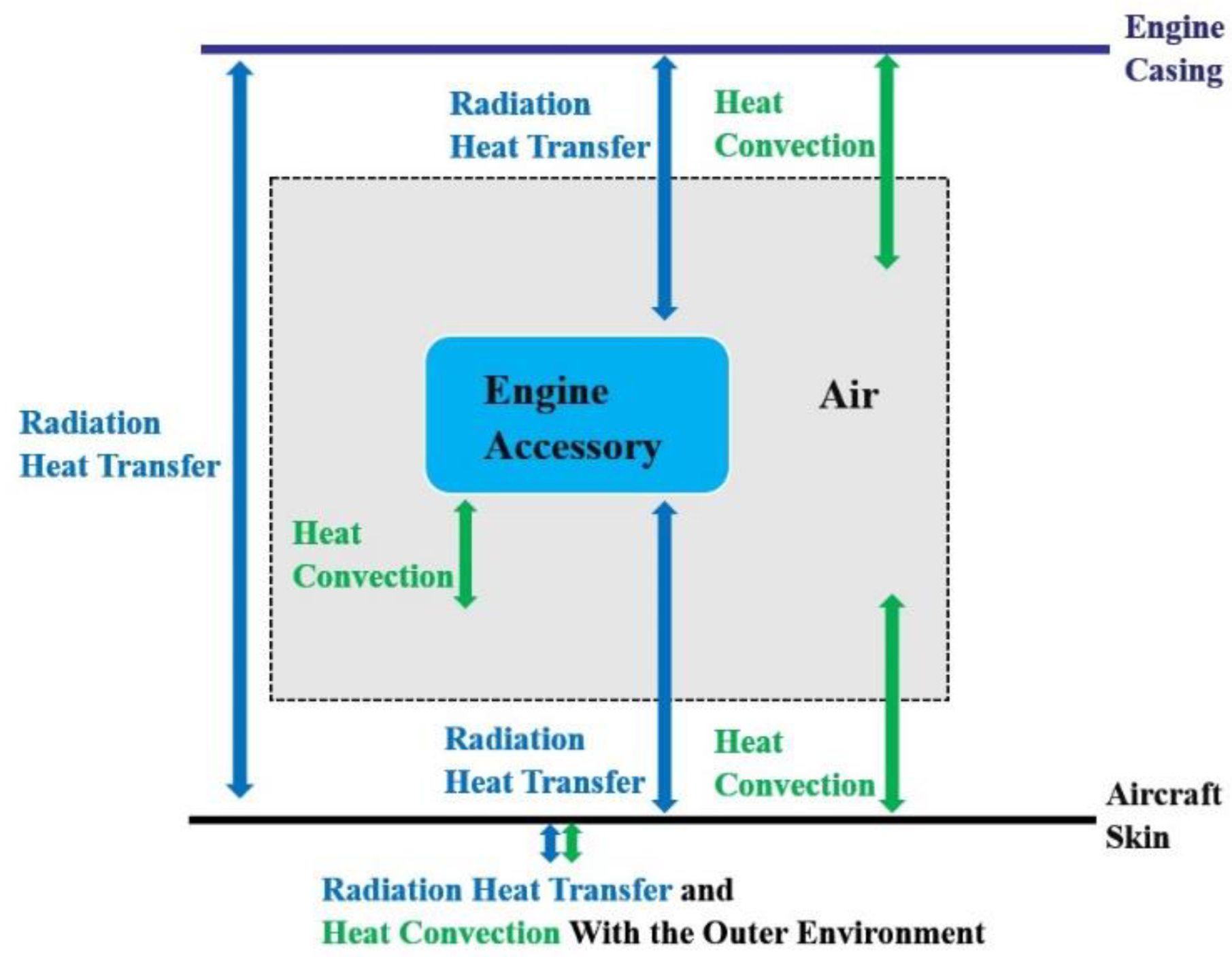
According to its physical model, the heat transfer process was analyzed based on the heat transfer principle. The engine compartment between the casing and the skin was analyzed and the heat transfer process between various components was obtained, as shown in Figure 3. The accessories were mainly subjected to radiation heat transfer from the casing and the skin, convection heat transfer with the air in the cabin and heat generation by themselves. When conducting the thermal protection of accessories to control their temperature, the commonly used thermal protection measures can be divided into active cooling, semi-active cooling and passive cooling according to the method of heat transfer. In the active cooling case, most of the heat is taken away by the cooling fluid, and thus, the heat cannot be transmitted to the next layer of the structure. Therefore, the accessories can be cooled by fuel to take away the heat of the accessories. In passive cooling, heat is absorbed or radiated out through the surface, and no additional heat sink is needed to remove the heat. Therefore, a heat insulation layer of aluminum silicate fiber was considered to be laid on the surface of the high-temperature wall and accessories to reduce the radiation heat transfer to the accessories from the surrounding high-temperature wall. In addition, a kind of paraffin phase change material could be laid on the surface of the accessories to absorb the heat generation inside.
The heat transfer of accessories involving the primary status of thermal environment parameters includes the related parameters of the air (temperature, density, velocity, etc.), the wall’s parameters (temperature, surface emissivity, etc.) and the internal heat. The parameters here were the state parameters of four parts: the skin surface, casing wall, cabin air and the internal heat generation of the accessories.
Therefore, in transient conditions, the temperature of the engine casing, skin, cooling airflow and accessories could be calculated using a lumped heat capacity method, namely, the following general formula:
( ρ c V ) d T d t = h A ( T T f ) + Q i n n e r + Q r a d + m ˙ in c in T in m ˙ out c out T out
Q r a d = E b 1 E b 2 1 ε 1 ε 1 A 1 + 1 A 1 X 1 , 2 + 1 ε 2 ε 2 A 2
where ( ρ c V ) d T d t is the energy change in the component in unit time, h A ( T T f ) is the convective heat transfer between the component and the fluid including air and fuel, Q i n n e r is the internal heat source of the component, Q r a d is the radiation heat transfer between the component and the surrounding parts, m ˙ in c in T in is the energy entering the component, m ˙ out c out T out is the energy going out of the component, ρ is the density, c is the specific heat capacity, V is the volume, h is the convective heat transfer coefficient on the surface, A is the surface area, T f is the fluid temperature, Q i n n e r is the inner heat source of the component, Q r a d is the radiation heat transfer, m ˙ in c in T in is the energy flowing into the system, m ˙ out c out T out is the energy flowing out of the system, E b is the emissive power and ε is the emissivity.

2.2. Simulation Model and Boundary Conditions

Because the casing temperatures of the different engine cabins along the axial location differ a lot, in order to give the boundary conditions of the simulation calculation more accurately, the simulation model was divided into 7 sections with the node partition as shown in Figure 4, along with each turbine and ramjet node, including walls, middle baffle, cabin air, engine casing and accessories.
In this study, Simulink, which is a dynamic simulation tool, was selected as the modeling environment for the integrated thermal management system of the TBCC engine cabin components. Moreover, an integrated simulation module for the integrated thermal management system of the TBCC engine components was established, as shown in Figure 5. In the simulation system’s overall encapsulated interface, users can set up the joint parameters, such as the environmental temperature and the initial temperature of the turbine cabin. For each section of the cabin-encapsulated interface, the corresponding geometric parameters and the corresponding thermal protection methods for the engine casing, skin and accessory can be set up. The aluminum silicate fiber layer, which has a low thermal conductivity, was considered to be put on the surface of the casing/baffle/accessories. Furthermore, air and fuel were the two main heat sinks in the engine, and thus, ventilation cooling and fuel cooling methods were chosen to cool the components. A kind of paraffin wax phase change material was used to absorb and store heat in the accessories. The corresponding thermal protection methods are shown in Table 1.
After the one-dimensional simulation model was established, the simulation calculation in the typical working conditions shown in Table 2 was carried out. WL represents the turbine engine casing, CY represents the ramjet engine casing and the ambient temperature was 300 K. The initial temperature of the accessories, baffle and other walls was 300 K.

3. Verification of the Model

The effectiveness of the simulation model was verified using the designed test bed below. The temperature increase of the accessory without thermal protection was experimentally studied, and the effect of the heat insulation layer on the accessory surface was verified. The reliability of the simulation model was verified using a data comparison.

3.1. Experimental System

The experimental system schematic diagram is shown in Figure 6. It heated the engine casing in each section to simulate the temperature distribution of a typical working condition of an actual engine in the process of an aircraft flight. The temperature acquisition and control system was used to collect temperature information and adjust the input voltage of the heating system so that the heating power of the heating system and the heat flux density on the casing surface were controlled to realize the segmented temperature control of the casing.
The experimental platform is shown in Figure 7. The whole experimental system consisted of two parts: the engine cabin simulation test platform and the high-temperature fuel test platform. The engine cabin simulator consisted of the engine cabin model test pieces, temperature control system, temperature signal acquisition system, thermal protection structure and so on. The test parts of the engine cabin model were designed according to the simplified engine model. The complicated small parts were simplified properly under the condition that the overall structure remained unchanged, i.e., the heat transfer and temperature field distribution in the cabin were not affected. Furthermore, the piping, wiring and other components arranged in the cabin were ignored. According to the surface temperature distribution of the casing along the axial direction, the original engine casing was divided into six sections, each with its own separate heating device. The separate temperature control for the heating device adopted a caterpillar ceramic heater. The ceramic bead decorated on the outside of the heating wire in the caterpillar shape can make the heating wire evenly distributed on the surface casing to not only ensure the uniformity of heating but also provide the effect of insulation. The accessories were designed according to the real structure and were arranged on the outside of the casing after scaling according to the spatial layout of real engine accessories and connected with fixed columns.
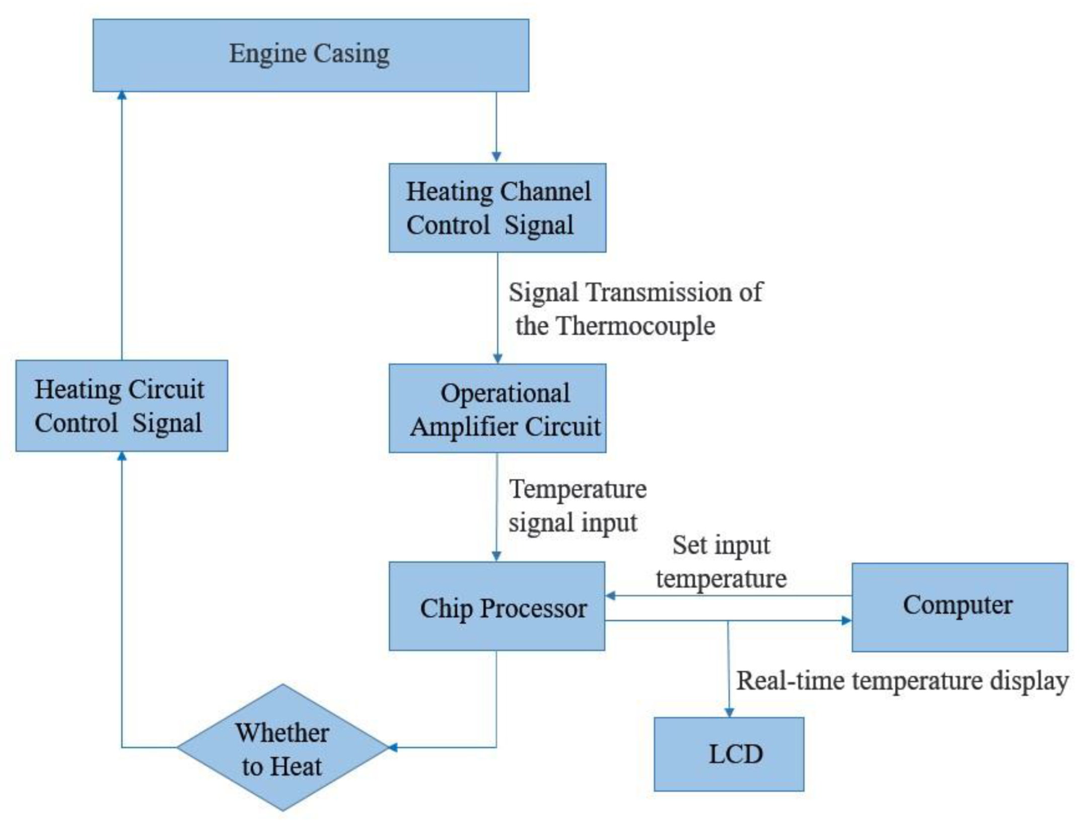
The temperature control system on the casing surface, which consisted of a distribution box, crawler ceramic heater, relay, power supply, temperature control thermocouple, temperature acquisition device and the temperature control logic, is shown in Figure 8. In the experiment, a K-type thermocouple was used to measure the temperature data and the thermocouple itself had an error of 1%.
The temperature on the casing surface was fed back to the computer control software through the four temperature control thermocouples embedded on the casing surface (taking the average value) and the temperature acquisition equipment. The temperature control module was operated on the temperature control software to adjust the output percentage of the control cabinet to control the tracked ceramic heater’s heating power in order for the engine casing surface temperature to reach the rated preset temperature. The temperature control system consisted of six channels corresponding to six heating segments in the casing. Two temperature measuring points were arranged on each accessory’s surface; they were distributed on the side near the casing and the side away from the casing. During the experiment, temperatures were collected on the side near the casing and the side away from the casing.

3.2. Experimental Validation of the Model

The temperature variation of the accessories with time obtained using one-dimensional simulation and under experimental conditions are shown in Figure 9 and Figure 10. Figure 9 is the results comparison of the turbine engine accessories between the simulation and experiment in the two different conditions: without any thermal protection and with a heat insulation layer (HIL) of 4 mm on the accessories. Figure 10 is for the ramjet engine accessories. In the two pictures, with the accumulation of heat, the accessory temperature rose higher and higher, and the accessory temperature simulation value trend was consistent with the experimental values. Moreover, at first, the temperature of the accessories rose quickly because the temperature differences between the accessories and the casing were large. With the temperature rise of the accessories, the temperature differences decreased such that the heat transfer was reduced and the temperature rise of the accessories became slower. For the accessory of the turbine engine with no thermal protection, the final experiment and simulation temperatures were 504 K and 486 K, respectively, and the deviation between them was 18 K, i.e., 3.7%. For the accessory of the ramjet engine with heat insulation layer, the final experiment and simulation temperatures were 501 K and 481 K, respectively, and the deviation between them was 20 K, i.e., 4.1%. For the accessory of the ramjet engine with no thermal protection, the final experiment and simulation temperatures were 591 K and 552 K, respectively, and the deviation between them was 39 K, i.e., 7.1%. For the accessory of the ramjet engine with heat insulation layer, the final experiment and simulation temperatures were 587 K and 563 K, respectively, and the deviation between them was 24 K, i.e., 4.2%. Therefore, it can be considered that the calculation results of this model were valid. The main reason for the errors was the accuracy of the measuring equipment. In the experiment, the K-type thermocouples that were used to measure the temperature data had an error of 1%. Based on the above results, the temperature distribution of accessories with different thermal protection measures can be further explored to obtain a variety of thermal protection cases.

4. Results and Discussions

4.1. Design of Different Thermal Protection Cases

The design of thermal protection cases aimed to control the temperature of the accessories below the following limits: 393 K for an accessory in the turbine engine and 423 K for an accessory in the ramjet engine. According to the analysis of cabin structure and heat transfer process, it is necessary to reduce the heat radiation of high-temperature casing and baffle to the accessories and take away the inner heat of accessories in order to control the temperature of the accessories. In terms of the thermal protection method for each component in Table 1, 19 thermal protection cases listed in Table 3 were set in the established one-dimensional simulation model, and the turbine engine accessory 1 with an internal heat source of 1000 W and the ramjet engine accessory 2 without an internal heat source were selected for analysis. In the table, N means no thermal protection measure, PCM is the shortage of the phase change material, VC is the shortage of ventilation cooling, FC is the shortage of fuel cooling and A2 means accessory 2. Regarding the thermal protection measures, the heat insulation layer was 5 mm of aluminum silicate fiber, and the phase change material wrapped in the accessories was 5 mm of paraffin wax. When there was no thermal protection, the temperature of accessory 1 was 413 K and that of accessory 2 was 578 K.

4.2. Impact of Different Thermal Protection Conditions on the Thermal Protection Effect

4.2.1. The Influence of Different Thicknesses of Heat Insulation Layers for the Casing on the Temperatures of the Accessories

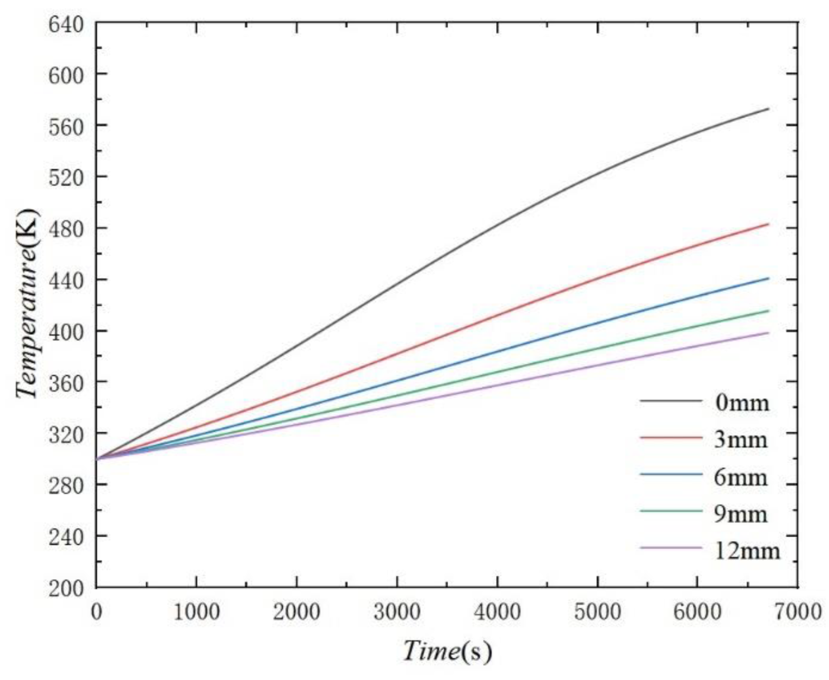
According to the thermal resistance method for heat conduction, the thickness of the heat insulation layer of the casing is proportional to the thermal resistance between the casing surface and the outer radiant surface of the casing. The greater the thickness of the heat insulation layer, the greater the thermal resistance could be, and the more the temperature of the outer radiant surface could decrease compared with the original casing surface. Heat insulation layer thicknesses of 0 mm, 3 mm, 6 mm, 9 mm and 12 mm were set for the calculation to make comparisons. The temperatures of accessory 1 and accessory 2 obtained are shown in Figure 11 and Figure 12, respectively.
As can be seen from Figure 11 and Figure 12, the greater the insulating layer thickness, the better the heat insulation effect, but for accessory 1 with an internal heat source, when adding an equal thickness of the heat insulation layer, the accessory temperature drop was significantly less than accessory 2 with no inner heat source. For example, adding a 3 mm heat insulation layer caused the final temperature of accessory 1 to fall by 20 K, and the final temperature of accessory 2 was reduced by about 100 K. Meanwhile, it was found that with the further thickness increase in the heat insulation layer, the descent rate of the accessory temperature reduced. For example, for accessory 2, when the insulation layer thickness increased from 0 mm to 3 mm, the final accessory temperature decreased by 100 K, and when the thickness increased from 3 mm to 6 mm, the accessory temperature decreased only by 40 K. According to the final temperature with each thickness, the heat insulation layer of 5 mm was chosen in the integrated thermal protection measures.

4.2.2. The Influence of Different Fuel Temperatures on the Temperatures of the Accessories

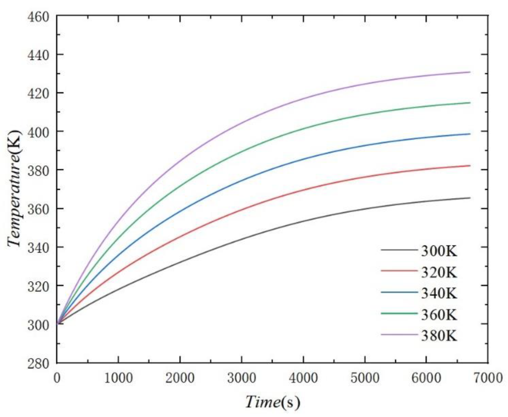
For accessory 1, with its fuel passing itself, the temperature of the accessory changed with the different temperatures of the fuel. As for accessory 2, there’s no fuel flowing through it, but it was in a relatively severe thermal environment, and the temperature of the accessory could be greatly reduced by using fuel cooling. Figure 13 and Figure 14 show the temperature distribution of accessory 1 and accessory 2 with fuel temperatures of 300 K, 320 K, 340 K, 360 K and 380 K. It can be concluded that for both accessories, the temperature of the accessories was tightly correlated with the fuel temperature. Moreover, in the temperature between 340 K and 360 K, the temperature of both accessories maintained a lower level below 430 K; considering the actual situation of the engine, the fuel temperature of 353 K was chosen to cool the accessories.

4.3. Analysis and Comparison of the Thermal Protection Cases

4.3.1. Effect of a Single Thermal Protection Measure

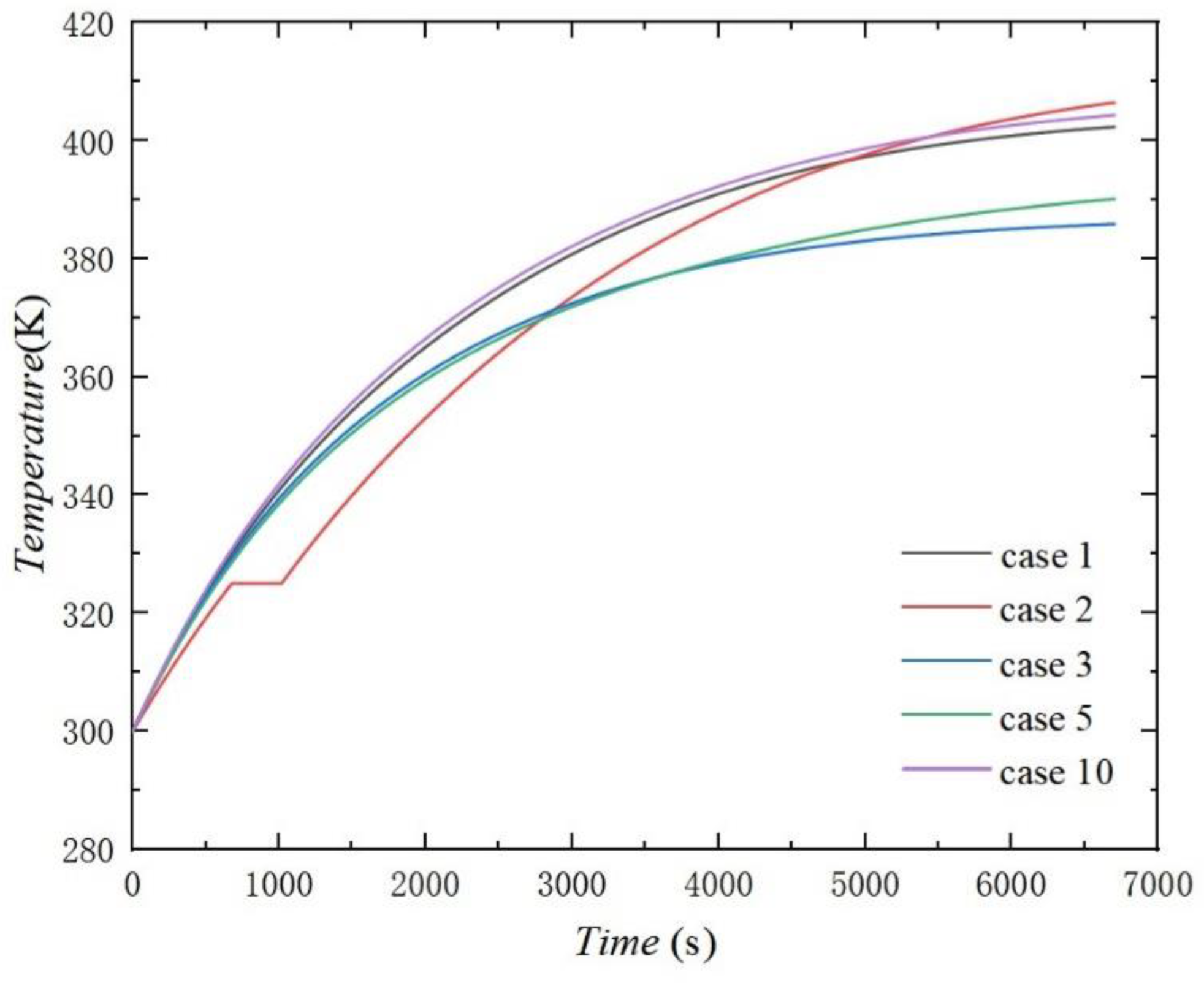
Regarding only taking a single thermal protection measure, including adding a heat insulation layer to accessories (case 1), adding phase change materials to accessories (case 2), ventilation cooling (case 3), fuel cooling for only accessory 2 (case 4), adding a heat insulation layer to the engine casing (case 5) or adding a heat insulation layer to the baffle (case 10), the temperature distribution of accessory 1 and accessory 2 are shown in Figure 15 and Figure 16, respectively.
For the turbine engine’s accessory 1 with internal fuel access and an internal heat source, the effects of case 3 (ventilation cooling) and case 5 (adding heat insulation layer to the casing) were better, and the temperature of accessory 1 could be kept at a relatively low level. In case 2, the temperature of accessory 1 could be kept at a lower level between 0 and 3000 s by laying phase change material on the accessory because the latent heat of the phase change material was substantial and could effectively absorb the heat of the accessory. At the same time, for case 10, when adding a heat insulation layer to the baffle, the layer with low thermal conductivity blocked the heat transmission from the ramjet engine to the turbine engine with a lower temperature so that the temperature of the ramjet engine accessory was higher than that without the heat insulation layer to the baffle, and the temperature of the turbine engine accessory was correspondingly reduced. Furthermore, the following conclusions were drawn from the different effects of adding a heat insulation layer to the casing on accessory 1 and accessory 2. For accessory 1 in the turbine engine, the heat not only came from the radiation heat transfer of the casing but also from its own internal heat production; for accessory 2 in the ramjet engine with no inner heat source, the heat came from the radiation heat transfer of the high-temperature casing only. Therefore, the effect of the heat insulation layer for the casing was more significant, and the accessory temperature decreased more for accessory 2.
Therefore, when only a single insulation measure was taken, adding a heat insulation layer to the casing achieved a better thermal protection effect for both accessories, while the effect of adding a heat insulation layer to the baffle was not good and would bring extra weight. Because the high-temperature casing was the main heat source for the accessories, adding a heat insulation layer could decrease the radiation heat from the casing effectively. For accessory 2 without an internal heat source, the effect of fuel cooling was very significant, but in a practical application, this will involve the design of a fuel passage inside the accessory and another auxiliary power unit.

4.3.2. Effect of Combined Thermal Protection for the Casing and Accessory

As the thermal radiation of high-temperature casing is one of the main sources of the heat of accessories, to improve the thermal environment of accessories and reduce the temperature of accessories, heat insulation materials with low thermal conductivity can be added to the casing. Thermal protection measures can also be applied to the accessory simultaneously. The diagram of the combined thermal protection for the casing and the accessory is shown in Figure 17 and the corresponding solution was the following: case 6, case 7, case 8 and case 9. Meanwhile, case 5 with a heat insulation layer on the casing only was selected to compare the effects of the combined thermal protection for the casing and accessories.
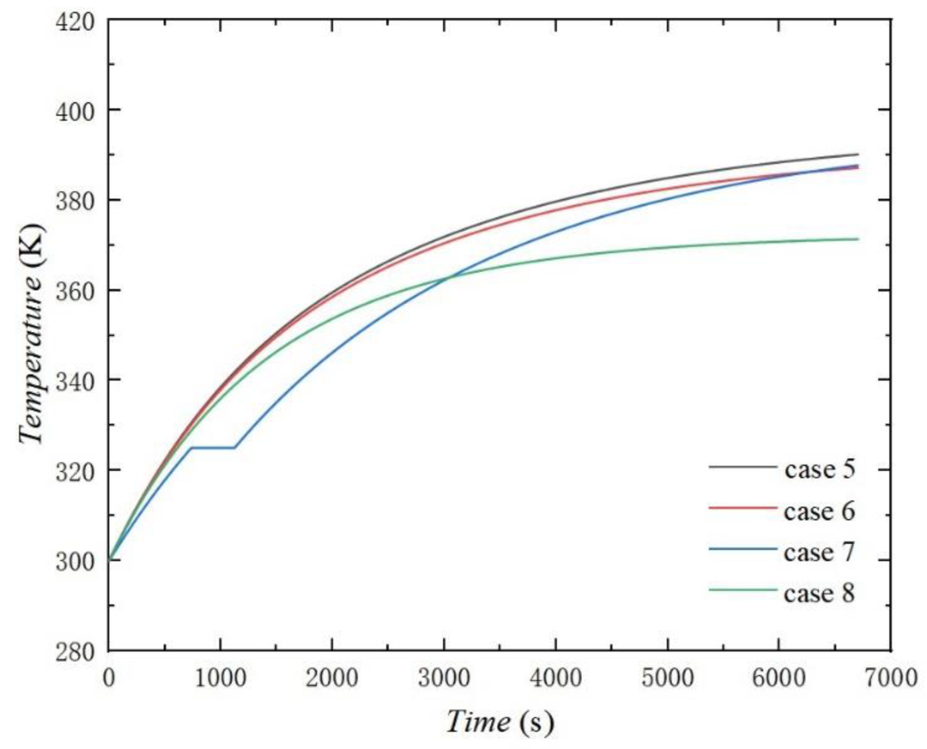
The temperature change of accessory 1 over time in cases 5–8 is shown in Figure 18. Case 8 (adding a heat insulation layer to the casing and ventilation cooling simultaneously) had a better effect. This was because the heat-insulating layer on the surface of the casing first reduced the lateral temperature, which radiated to the accessory, and ventilation cooling could take away part of the heat of the surface outside the casing, further reducing the outside surface temperature. In addition, ventilation cooling could directly take away the heat of the accessories through convection heat transfer, thus reducing the temperature of the accessories. Comparing case 5 and case 8 showed that further ventilation cooling could reduce the temperature of accessory 1 with an internal heat source by 20 K. In addition, the thermal protection effect of case 7 was also very valid, and the temperature of accessory 1 could be maintained at a low level for the time of 0–3000 s. By comparing case 5 and case 6, it was found that due to the internal heat source of accessory 1, the effect of adding a heat insulation layer to the accessory was not so obvious on the basis of adding a heat insulation layer to the casing.
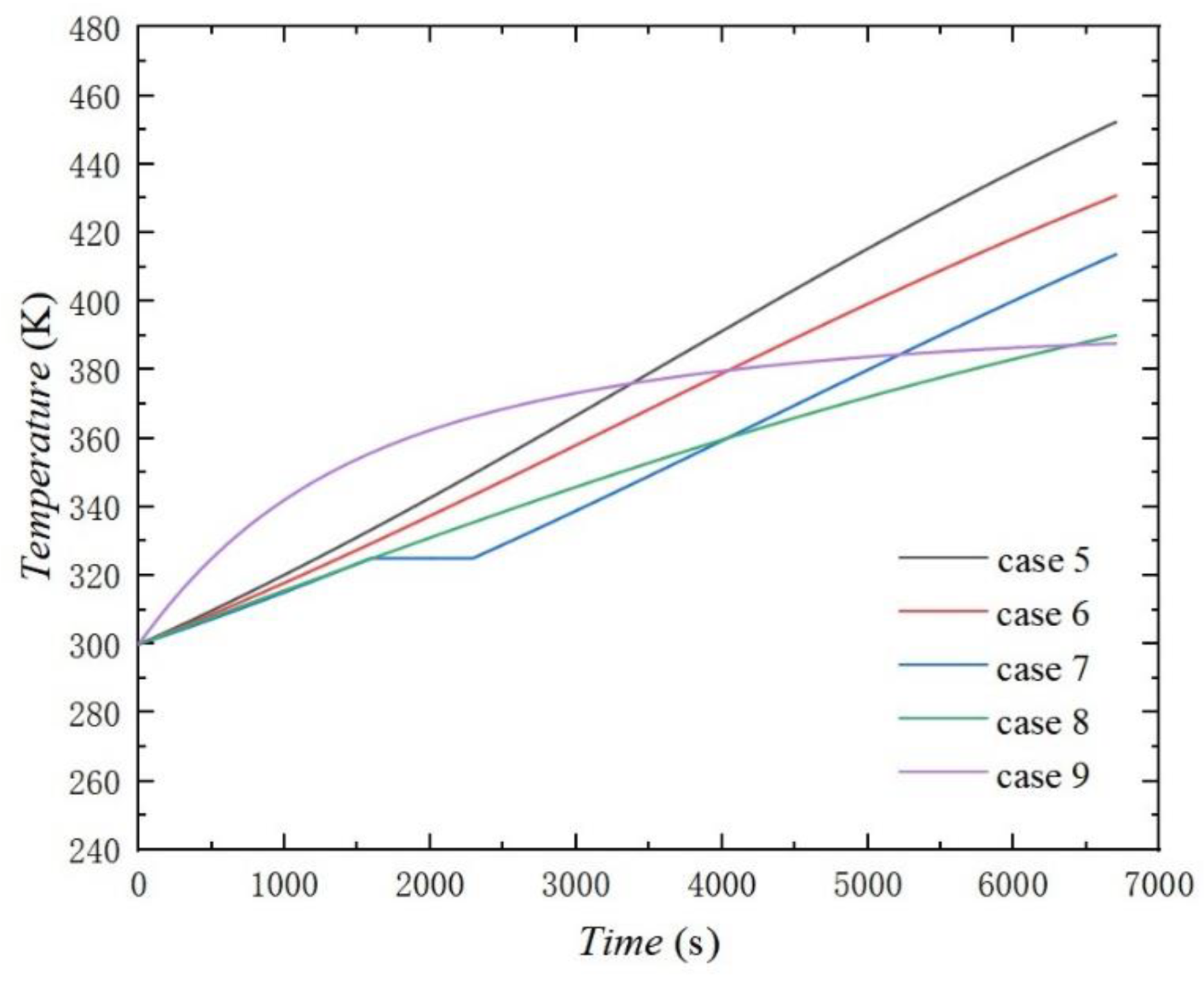
The temperature changes of accessory 2 over time in cases 5–9 are shown in Figure 19, in which the effect of adding an insulation layer to the casing and fuel cooling simultaneously was the best. This was because, in the case of no inner heat source, fuel cooling could take away the heat in the accessory via heat convection. Moreover, because of the high heat capacity of the fuel, in the process of heat convection, the fuel temperature rise was prolonged, which caused the temperature difference of the heat convection to maintain a higher level such that a large amount of heat could be taken away by the heat convection between the fuel and the accessories. By comparing cases 5 and 6, it was found that since there was no internal heat source in accessory 2, heat insulation for accessory 2 could reduce the transfer of radiated heat from the casing to the interior of the accessory, thus reducing the overall temperature of the accessory. By contrasting cases 6 and 7, it was found that because the heat insulation of the casing reduced the radiation to the accessory, attaching a phase change material at the same time could achieve a good effect on temperature control to keep the accessory at a lower temperature for more extended periods and make the final temperature of the accessory lower compared with adding heat insulation layer not only to the casing but also to the accessory.
According to the analysis, for accessory 1 with an internal heat source, adding the heat insulation layer to the casing and ventilation cooling simultaneously had the most significant effect, and thus, the thermal protection case can be given priority when the cold air is sufficient. In addition, the case that involved adding a heat insulation layer and putting phase change material on the accessory had a relatively good thermal protection effect and can keep the accessory at a low working temperature for a longer time. For accessory 2 without an internal heat source, the effect of adding a heat insulation layer to the casing and fuel cooling simultaneously was the most significant, followed by adding a heat insulation layer to the casing and ventilation cooling simultaneously. Moreover, adding a heat insulation layer and putting phase change material on the accessory simultaneously also had a relatively good thermal protection effect.

4.3.3. Effect of Combined Thermal Protection for the Baffle and Accessory

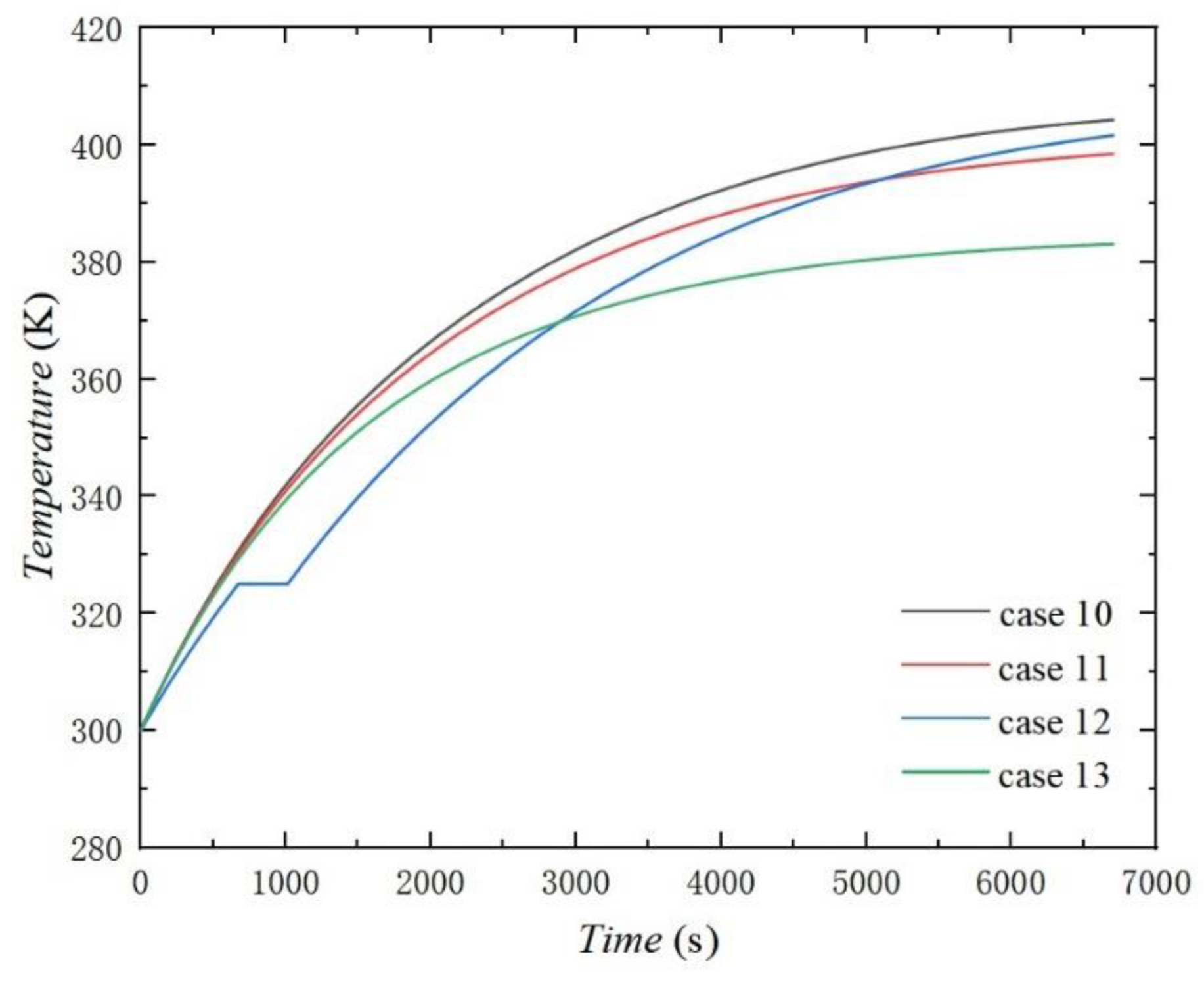
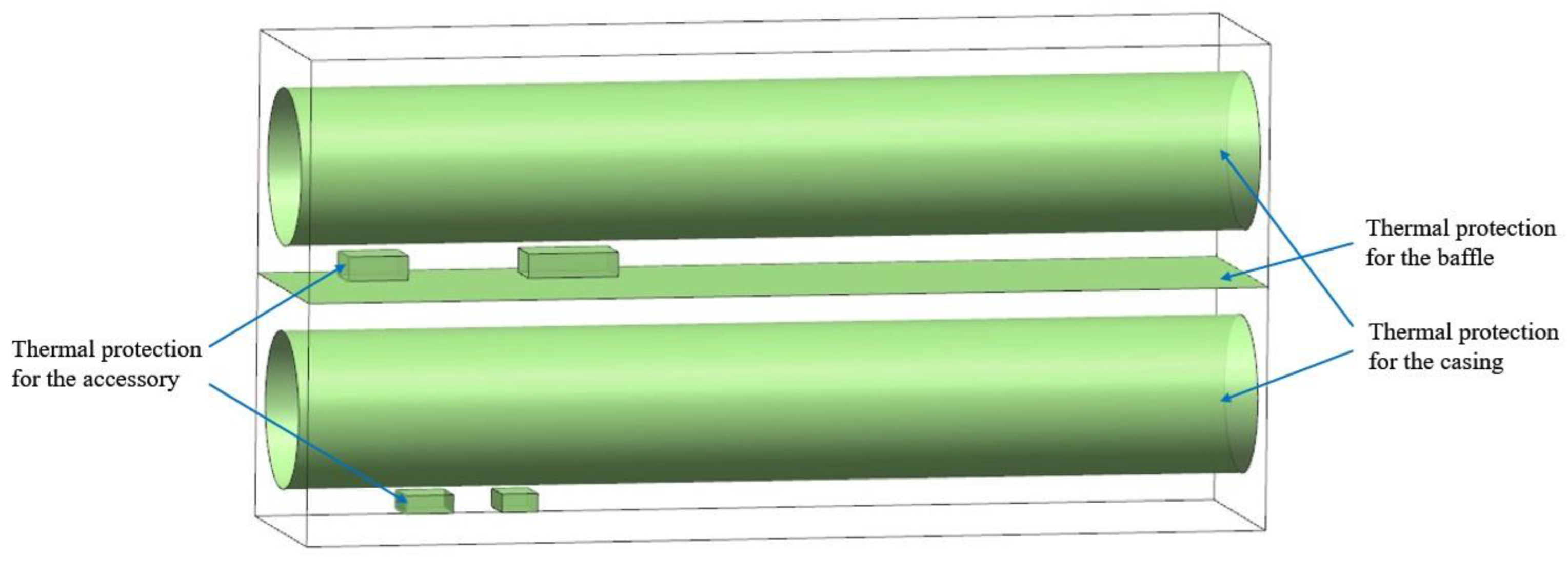
The diagram of the combined thermal protection for the baffle and the accessory is shown in Figure 20. The temperature change of accessory 1 over time in cases 10–13 is shown in Figure 21. It can be seen that the overall thermal protection effect of adding a heat insulation layer to the baffle was worse than that of the casing. The temperature of accessory 1 when only adding the heat insulation layer to the baffle reached 405 K, while adding the same to the casing was 390 K; this was because the thermal radiation from the casing was one of the primary sources of the accessory and the heat and thermal protection from the main heat source allowed for controlling the temperature of the accessory more effectively.
By contrasting cases 11 and 12, it can be seen that the temperature of accessory 1 was still relatively high with a heat insulation layer on the baffle, and adding phase change material to the accessory in the meanwhile could maintain the accessory temperature at a lower range during 0–5000 s than adding a heat insulation layer to the accessory. By contrasting cases 12 and 13, it was found that adding a phase change material to the accessory in the meanwhile could make the temperature of the accessory lower from 0 to 3000 s, but it is better to use ventilation if the temperature is to be kept at a lower level during the whole flight.
The temperature distribution of accessory 2 in cases 10–14 is shown in Figure 22. It can be seen that because the temperature of the ramjet engine casing was higher when only adding the heat insulation layer to the baffle, the accessory temperature remained at high levels such that accessory 2 cannot undertake its normal work. Thus, an additional measure was taken, however, only fuel cooling at the same time could keep the accessory temperature at a lower level. Therefore, the combined measures of taking thermal protection for the baffle and accessory simultaneously did not apply to accessory 2.

4.3.4. Effect Comparison of Combined Thermal Protection for the Casing, Baffle and Accessory

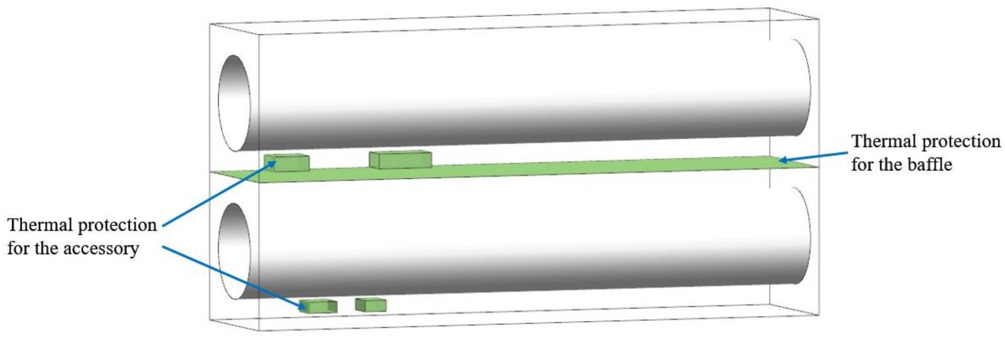
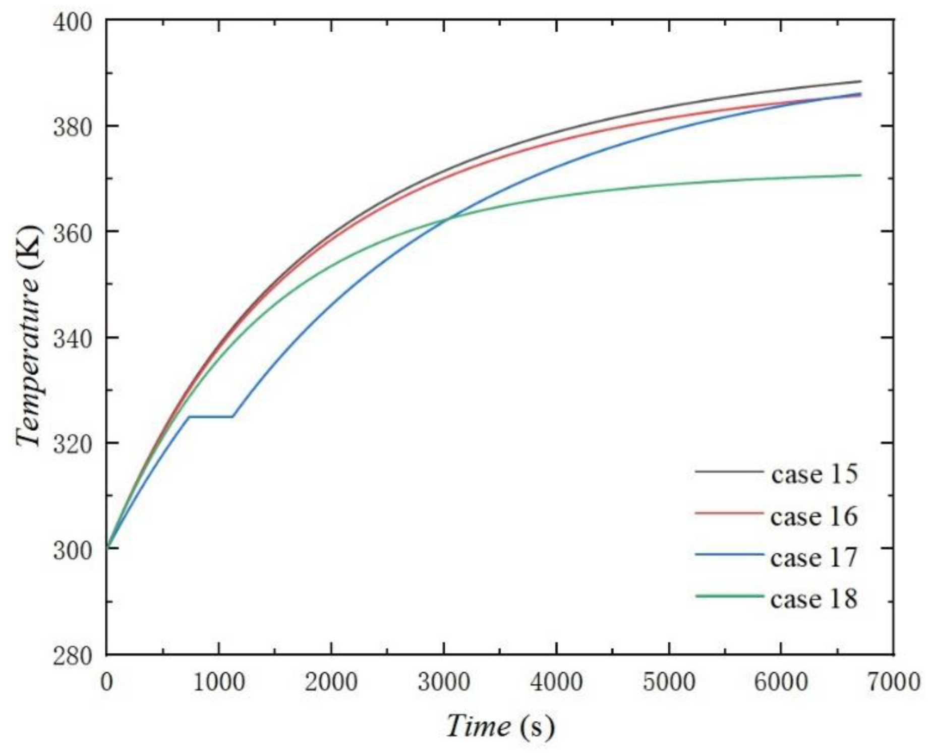
The diagram of combined thermal protection for the casing, baffle and accessory is shown in Figure 23. The temperature distribution with time for accessory 1 in cases 15–18 is shown in Figure 24. It can be seen that the temperature of accessory 1 could be kept at a lower level when the casing, baffle and accessory were receiving thermal protection simultaneously. Adding a heat insulation layer to the casing and ventilation cooling simultaneously has the best effect. By comparing cases 16 and 17, it was found that adding phase change material to the accessory could keep the temperature of the accessory at the lowest level between 0–3000 s in these cases, and the final temperature when adding phase change material to the accessory 1 was almost the same as adding a heat insulation layer to accessory 1. This indicates that better thermal protection could be achieved by adding phase change materials to accessories under the condition that both the casing and baffle had added heat insulation layers.
The temperature distribution with time for accessory 2 in cases 15–18 is shown in Figure 25. By comparison, it was further confirmed that adding a phase change material to the accessory had better thermal protection than adding a heat insulation layer to the accessory under the circumstance that both the casing and baffle had an added heat insulation layer. Under this circumstance, the thermal protection effect of fuel cooling was poor because the temperature difference between the fuel and accessory 2 was smaller such that the surface convection heat transfer of the fuel and accessory 2 was reduced.

4.3.5. Comparison of All Cases

The performance of the thermal protection was directly related to the final temperature of the two accessories. Furthermore, the impact on the flight performance of thermal protection systems also needed to be measured. Therefore, the total system take-off weight method [26] was adopted, in which the penalty to flight performance was equivalent to the take-off fuel weight. Based on the penalty sources listed in Table 4, the fuel weight penalties of all cases were calculated. The design variable numbers of the different concepts are given in Table 4. The accessories’ final temperature and fuel weight penalties for all cases are shown in Table 5.
W f i x w e i g h t is the penalty caused by an added fixed weight, kg; ( S F C ) t h is the specific fuel consumption for thrust, k g / ( h d a N ) ; L / D is the lift/drag ratio; t is the time, h; W F is the weight of the system, k g , including the weight of heat insulation layer, phase change material and fuel power devices; W R A is the penalty caused by the ram airflow, kg; w r is the mass flow of air, k g / s ; v is the flight speed, m / s ; W b l e e d is the penalty caused by the bleed airflow, kg; T t b is the turbine inlet temperature, K ; w b is the mass flow of bleed air, k g / h ;   W h o r s e p o w e r is the penalty caused by shaft horsepower extraction, kg; ( S F C ) p is the specific fuel consumption for power, k g / ( h k W ) ; P is the power being consumed, k W [26].
The temperature drop compared with the temperature of accessory 1 and accessory 2 without thermal protection and the derivative of the fuel weight penalty of each case are shown in Figure 26. The larger the temperature drop and the derivative of added fuel weight, the better the thermal protection effect of the case. It was found that for accessory 2 without an internal heat source and no fuel passage, the effect of case 19 (adding a heat insulation layer to the casing and fuel cooling simultaneously) was the best, followed by case 18 (adding a heat insulation layer to the casing and ventilation cooling simultaneously). Under the circumstance of adding a heat insulation layer to the casing, the effect of case 6 (adding phase change materials to the accessory simultaneously) was better than case 5 (adding a heat insulation layer simultaneously). Moreover, adding thermal protection measures to the casing and accessories at the same time not only provided a good protection effect but also added less weight compared with adding thermal protection for the casing, baffle and accessories. In the case of thermal protection for the casing and accessories at the same time, for accessories with an internal heat source and fuel access, the effect of case 18 (adding a heat insulation layer to the casing and ventilation cooling simultaneously) was the best, followed by case 6 (adding a heat insulation layer to the casing and accessories with a phase change material). Furthermore, the active cooling mode including ventilation and fuel cooling had better cooling performance but added a higher fuel weight penalty.
Based on the above analysis, case 18 and case 19 had better thermal protection performance. In addition to the temperature drop and the added fuel penalty, the cases could also be assessed using the temperature margin; utilization efficiency of cold sources, including cold air and fuel; and the additional expenditure, as shown in Figure 27. The temperature margin was the difference between the allowable and actual temperature. Energy utilization was the ratio of the heat taken away by the cold source to the cooling capacity. Moreover, the expenditure included the material cost and processing charge. It can be seen that case 18 had a larger temperature margin and less expenditure; however, its added fuel penalty was bigger and its energy utilization of cold air needed to be improved.

5. Conclusions

A rapid simulation model of a TBCC engine cabin was established and validated via an experiment, and 19 different thermal protection cases were proposed and calculated in a specific working condition using the model. The turbine engine accessory 1 with an internal heat source of 1000 W and an internal fuel flow and a ramjet engine accessory 2 with no internal heat source were selected to analyze the thermal protection effects of these cases. The results show the following:
(1)
A rapid simulation model was established and the results comparison of accessories between the simulation and experiment was made in the two different conditions: without any thermal protection and adding a heat insulation layer (HIL) of 4 mm to the accessories. The largest deviation between the simulation and experiment results was 7.1%.
(2)
Based on this, this article also discusses the thermal protection effects of different heat insulation layer thicknesses and the fuel temperatures based on their calculation and analysis. The heat insulation layer thicknesses of 5 mm and the fuel temperature of 353 K were finally chosen regarding the thermal protection measures.
(3)
For accessory 1 with an internal heat source of 1000 W and internal fuel access, the thermal protection effect of adding a heat insulation layer and ventilation was the best, which caused the temperature of accessory 1 to decrease by 43 K.
(4)
For accessory 2 without an internal heat source, the thermal protection effect of adding a heat insulation layer to the casing and fuel cooling simultaneously was the most ideal, which caused the temperature of accessory 2 to decrease by 190 K. Moreover, the effect of adding a heat insulation layer to the casing was more significant in accessory 2 without an internal heat source.
(5)
Case 18 and case 19 were assessed in terms of the temperature drops of the two accessories; added fuel penalty; temperature margin; utilization efficiency of cold sources, including cold air and fuel; and the additional expenditure. Case 18 had a larger temperature margin and less expenditure, but its energy utilization of cold air needs to be improved.
In general, the simulation model of the TBCC engine cabin established here was convenient for analyzing the performance of a thermal protection system for the accessories of a TBCC engine. It was integrated with a variety of thermal protection methods compared with previous studies and the temperature of accessories could be controlled by the combination of thermal protection methods to keep the normal operation of the engine in a specific working condition. Moreover, these thermal protection cases were estimated with a comprehensive assessment. Furthermore, the model can also be extended to explore the performance of a thermal protection system for the accessories in different flight conditions in a follow-up study.

Author Contributions

Funding acquisition, W.L. conceptualization, J.Z. and W.L.; methodology, J.Z.; software, J.Z.; validation, J.Z. and D.L.; formal analysis, J.Z.; writing—original draft preparation, J.Z. All authors have read and agreed to the published version of the manuscript.

Funding

This research was funded by the 1912 Project of China (2019-JCJQ-DA-001–108).

Institutional Review Board Statement

Not applicable.

Informed Consent Statement

Not applicable.

Data Availability Statement

The data is unavailable due to privacy.

Acknowledgments

This work was supported by the 1912 Project of China (2019-JCJQ-DA-001–108).

Conflicts of Interest

The authors declare that there is no conflict of interest.

References

  1. Yu, C.Z.; Liu, W.H. Research progress of aerothermal prediction technology for hypersonic vehicle. Aeronaut. Sci. Technol. 2021, 322, 14–21. [Google Scholar]
  2. Cao, Y.G.; Zhou, W.; Wang, P. Development of integrated thermal management system for aircraft and test flight verification technology. China Sci. Technol. Inf. 2020, 2020, 42–44. [Google Scholar] [CrossRef]
  3. Tu, M.; Yuan, G.M.; Xue, F. Application of integrated thermal management in advanced fighter system development. Acta Aeronaut. Et Astronaut. Sin. 2020, 41, 129–139. [Google Scholar]
  4. Luo, Z.H.; Li, S.Q.; Huang, C.Z. Research on next generation aircraft thermal management technology. Aeronaut. Sci. Technol. 2015, 26, 6–12. [Google Scholar]
  5. Gao, F.; Yuan, X.G. Fuel thermal management system of high performance fighter aircraft. J. Beijing Univ. Aeronaut. Astronaut. 2009, 35, 1353–1356. [Google Scholar]
  6. Fen, W.K. Review on reliability test of aero-engine components. Stand. Technol. 2021, 2021, 165–167. [Google Scholar] [CrossRef]
  7. Zhang, J.; Qin, Q.; Yang, Z.B. Simulation of Ambient Temperature Monitoring for Electronic Equipment Cabins of High-Speed Aircraft. Aeronaut. Comput. Tech. 2021, 51, 20–23. [Google Scholar] [CrossRef]
  8. Chen, B.; Gui, F.; Li, Q.; Kang, Y. Study on the development approach of foreign over/under TBCC engine technology. Gas Turbine Exp. Res. 2019, 32, 57–62. [Google Scholar] [CrossRef]
  9. Liu, X.B.; Luo, Y.P.; Zeng, H. An overview of key technology and test facility for turbine-based combined cycle propulsion study overseas. Gas Turbine Exp. Res. 2016, 29, 51–56. [Google Scholar] [CrossRef]
  10. Liu, Y.H.; Chang, Z.Z. Study on thermal environment of element assembly in engine cabin of high speed aircraft. Sci. Technol. Eng. 2017, 17, 151–159. [Google Scholar] [CrossRef]
  11. Liu, Y.H.; Zhou, Y.P.; Gao, J.J. Thermal protection design and analysis of a type of composite engine cabin accessories. J. Therm. Sci. Technol. 2017, 16, 193–200. [Google Scholar] [CrossRef]
  12. Wang, X.T.; Zhang, J.Z.; Shan, Y. Internal heat transfer and skin temperature reduction law of engine nacelle. J. Aerosp. Power 2016, 31, 1121–1126. [Google Scholar] [CrossRef]
  13. Xue, Y.J.; Liu, J.C. Preparation of Flexible Fiber Blankets and Their Elasticity and Thermal Insulation Properties. Mater. Re-Ports 2023, 37, 1–13. Available online: http://kns.cnki.net/kcms/det-ail/50.1078.TB.20220516.1503.024.html (accessed on 16 May 2022).
  14. Lin, J.; Liu, Y.F.; Yin, B.H.; Tan, J.Y.; Chen, X.C. Design of a phase change material heat sink and analysis of its heat dissipation performance. Spacecr. Environ. Eng. 2020, 37, 390–396. [Google Scholar]
  15. Albeirutty, M.H.; Alghamdi, A.S.; Najjar, T.S. Heat transfer analysis for a multistage gas turbine using different blade-cooling schemes. Appl. Therm. Eng. 2004, 24, 563–577. [Google Scholar] [CrossRef]
  16. Eric, J.G.; Dan, H. Thermal Management and Fuel System Model for TBCC Dynamic Simulation. In Proceedings of the 46th AIAA/ASME/SAE/ASEE Joint Propulsion Conference & Exhibit, Nashville, TN, USA, 25–28 July 2010; pp. 25–28. [Google Scholar]
  17. Pangborn, H.C.; Hey, J.E.; Deppen, T.O.; Alleyne, A.G.; Fisher, T.S. Hardware-in-the-Loop Validation of Advanced Fuel Thermal Management Control. J. Thermophys. Heat Transf. 2017, 31, 901–909. [Google Scholar] [CrossRef]
  18. Lou, D.C.; Guo, W.; Wang, Z.G.; Wang, Y.H. Integrated Thermal Management System Design for Advanced Propulsion System. Mech. Aerosp. Eng. 2012, 2012, 694–700. [Google Scholar]
  19. Jiang, J.; Zhang, R.L.; Yang, Y.; Liu, W.X. Thermal protection of scramjet typical components. J. Aerosp. Power 2013, 28, 1921–1926. [Google Scholar] [CrossRef]
  20. Zhou, Y.; Miao, L.; Zhang, F.H.; Tian, P.; Yang, Y.W. Thermal design of electronic equipment in an aviation engine cabin. Sci. Technol. Eng. 2020, 20, 11803–11808. [Google Scholar]
  21. Li, B.; Zhang, D.H.; Hong, L. Simulation and experimental verification of aero-engine fuel thermal management system. Gas Turbine Exp. Res. 2019, 32, 29–34. [Google Scholar]
  22. Liu, K.L.; Wang, C.; Wei, T.S.; Li, L.L. Rapid simulation platform for integrated thermal management system of high-speed aircraft. Adv. Aeronaut. Sci. Eng. 2020, 11, 353–359. [Google Scholar] [CrossRef]
  23. Raczkowski, B.C.; Jones, N.; Deppen, T.; Lucas, C.; Yeu, R.; Walters, E.; Donovan, A.; Patnaik, S.; Bodie, M. A MATLAB/Simulink based co-simulation approach for a vehicle systems model integration architecture. SAE Int. J. Adv. Curr. Pract. Mobil. 2020, 2, 1150–1159. [Google Scholar]
  24. Yang, B.; Deng, J. Modeling and simulation of aircraft fuel system under the framework of electromechanical integrated management. J. Beijing Univ. Aeronaut. Astronaut. 2013, 39, 880–884, 889. [Google Scholar]
  25. Fadel, M.Z.; Rabie, M.G.; Youssef, A.M. Motion control of an aircraft electro-hydraulic servo actuator. IOP Conf. Ser. Mater. Sci. Eng. 2019, 610, 012073. [Google Scholar] [CrossRef] [Green Version]
  26. SAE. Aircraft Fuel Weight Penalty Due to Air Conditioning; This document has been declared, Stabilized “by SAE”: SAE AIR 1168/6A-2011; Society of Automotive Engineers: Warrendale, PA, USA, 1989. [Google Scholar]
Figure 1. Structure of the engine cabin and accessories.
Energies 16 02713 g001
Figure 2. Schematic diagram along the radial direction of engine compartments.
Energies 16 02713 g002
Figure 3. Heat transfer process analysis of various components in a TBCC engine cabin.
Energies 16 02713 g003
Figure 4. Node division.
Energies 16 02713 g004
Figure 5. Simulation model of the accessory thermal protection cases.
Energies 16 02713 g005
Figure 6. Experimental system schematic diagram.
Energies 16 02713 g006
Figure 7. Experimental platform.
Energies 16 02713 g007
Figure 8. The temperature control logic.
Energies 16 02713 g008
Figure 9. Comparisons between the experimental results and the numerical results for an accessory in the turbine engine.
Energies 16 02713 g009
Figure 10. Comparisons between the experimental results and the numerical results for an accessory in the ramjet engine.
Energies 16 02713 g010
Figure 11. Temperature of accessory 1 when adding a heat insulation layers of different thicknesses to the casing.
Energies 16 02713 g011
Figure 12. Temperature of accessory 2 when adding heat insulation layers of different thicknesses to the casing.
Energies 16 02713 g012
Figure 13. Temperature of accessory 1 with different fuel temperatures.
Energies 16 02713 g013
Figure 14. Temperature of accessory 2 with different fuel temperatures.
Energies 16 02713 g014
Figure 15. Temperature of accessory 1 with a single thermal protection measure.
Energies 16 02713 g015
Figure 16. Temperature of accessory 2 with a single thermal protection measure.
Energies 16 02713 g016
Figure 17. The diagram of the combined thermal protection for the casing and the accessory.
Energies 16 02713 g017
Figure 18. Temperature of accessory 1 when the casing and accessory were thermally protected.
Energies 16 02713 g018
Figure 19. Temperature of accessory 2 when the casing and accessory were thermally protected.
Energies 16 02713 g019
Figure 20. The diagram of the combined thermal protection for the casing and accessory.
Energies 16 02713 g020
Figure 21. Temperature of accessory 1 when the baffle and accessory were thermally protected.
Energies 16 02713 g021
Figure 22. Temperature of accessory 2 when the baffle and accessory were thermally protected.
Energies 16 02713 g022
Figure 23. The diagram of combined thermal protection for the casing, baffle and accessory.
Energies 16 02713 g023
Figure 24. Temperature of accessory 1 when the casing, baffle, and accessory were thermally protected.
Energies 16 02713 g024
Figure 25. Temperature of accessory 2 when the casing, baffle and accessory were thermally protected.
Energies 16 02713 g025
Figure 26. Thermal protection effect comparison of all cases.
Energies 16 02713 g026
Figure 27. The comprehensive assessment of case 18 and case 19.
Energies 16 02713 g027
Table 1. Thermal protection method for each component.
ComponentThermal Protection Method
Engine casingAdding heat insulation layer (aluminum silicate fiber layer)
BaffleAdding heat insulation layer (aluminum silicate fiber layer)
AccessoryAdding heat insulation layer (aluminum silicate fiber layer)
Adding phase change material (paraffin wax)
Ventilation cooling
Fuel cooling
Table 2. Temperature distribution on the casing surface.
Casing SectionCasing Temperature (K)Casing SectionCasing Temperature (K)
WL-1467CY-1680
WL-2526CY-2680
WL-3564CY-3680
WL-4582CY-4680
WL-5605CY-5680
WL-6619CY-6680
WL-7619CY-7680
Table 3. Integrated thermal protection cases.
Engine CasingBaffleAccessory 1Accessory 2
Case1NNHILHIL
Case2NNPCMPCM
Case3NNVCVC
Case4NNNFC
Case5HILNNN
Case6HILNHILHIL
Case7HILNPCMPCM
Case8HILNVCVC
Case9HILNNFC
Case10NHILNN
Case11NHILHILHIL
Case12NHILPCMPCM
Case13NHILVCVC
Case14NHILNFC
Case15HILHILNN
Case16HILHILHILHIL
Case17HILHILPCMPCM
Case18HILHILVCVC
Case19HILHILNFC
Table 4. Penalty sources and equations.
Penalty SourceTake-Off Fuel Weight
Fixed weight W f i x w e i g h t = ( exp ( ( S F C ) t h t L / D ) 1 ) W F
Ram air W R A = ( exp ( ( S F C ) t h t L / D ) 1 ) L / D g w r v
Bleed air W b l e e d = 0.0186 ( exp ( ( S F C ) t h t L / D ) 1 ) L / D ( S F C ) t h ( T t b 2000 ) w b
Shaft horsepower extraction W h o r s e p o w e r = ( exp ( ( S F C ) t h t L / D ) 1 ) L / D ( S F C ) t h P ( S F C ) p
Table 5. Integrated thermal protection calculation results and consumption.
Temperature of Accessory 1 (K)Temperature of Accessory 2 (K)Added Fuel Penalty (kg)
Case14025240.02103
Case24065230.06308
Case338550535.75
Case44024223.819
Case53904520.4832
Case63874300.5042
Case73874130.5462
Case837139036.24
Case93903874.302
Case104045800.1264
Case113985300.1474
Case124015300.1895
Case1338350935.88
Case144044253.945
Case153884550.6096
Case163854330.6306
Case173864160.6727
Case1837039136.36
Case193883884.428
Disclaimer/Publisher’s Note: The statements, opinions and data contained in all publications are solely those of the individual author(s) and contributor(s) and not of MDPI and/or the editor(s). MDPI and/or the editor(s) disclaim responsibility for any injury to people or property resulting from any ideas, methods, instructions or products referred to in the content.