Abstract
Maximum power point tracking (MPPT) through an effective control strategy increases the efficiency of solar panels under rapidly changing atmospheric conditions. Due to the nonlinearity of the I–V characteristics of the PV module, the Sliding Mode Controller (SMC) is considered one of the commonly used control approaches for MPPT in the literature. This paper proposed a Backstepping SMC (BSMC) method that ensures system stability using Lyapunov criteria. A fuzzy inference system replaces the saturation function, and a modified SMC is used for MPPT to ensure smooth behavior. The proposed Fuzzy BSMC (FBSMC) parameters are optimized using a Particle Swarm Optimization (PSO) approach. The proposed controller is tested through various case studies on account of MPP’s dependence on temperature and solar radiation. The controller performance is assessed in partial shading conditions as well. The simulation results show that less settling time, a small error, and enhanced power extraction capability are achieved by applying the PSO-based FBSMC approach compared to the conventional BSMC- and ABC-based PI control presented in previous research in different scenarios. Moreover, the proposed approach provides faster adaptation to temperature and solar radiation variation, ensuring faster convergence to the MPP. Finally, the robustness of the proposed controller is validated by providing variation within the system components. The result of the proposed controller clearly indicates the lowest value of RMSE measured between PV voltage and the reference voltage, as well as the RMSE between PV power and maximum power. The results also show that the proposed MPPT controller exhibits the highest dynamic efficiency and mean power.
1. Introduction
Due to the increasing global demand for energy, environmental concerns, air pollution from fossil fuel use, and rapid depletion of such fuel, renewable resources have attracted attention. Solar energy attracted a great deal of research attention as an unlimited, safe, CO2-free, and clean alternative energy resource. For example, in [1], some grid mix scenarios with increased photovoltaic (PV) capacity were assessed that improved energy use and reduced greenhouse gas emissions. In [2], life-cycle analysis (LCA) was used to assess the environmental aspect of future PV systems. As an effective way to increase extracted power from PV panels, the MPPT approach and an appropriate control approach are required.
MPPT algorithms are essentially categorized based on two distinct operating conditions, i.e., rapidly changing irradiance and partial shading conditions. Under rapidly changing irradiance, a single MPP exists which is tracked by the MPPT algorithm. On the other hand, during partial shading conditions, two or more MPPs exist and the role of the MPPT algorithm is to track the GMPP. In the proposed study, the authors have developed a MPPT algorithm for rapidly changing irradiance conditions.
The configuration, control method, and characteristics of different MPPT methods were examined in [3], some of which are as follows. The constant voltage method is the simplest MPPT method and in each time instant it compares PV voltage with the reference voltage obtained under standard test conditions to change the duty ratio for MPPT [4]. Its disadvantage is not paying attention to radiation and temperature. The open-circuit voltage method compensates for the shortcomings of the constant voltage method. Since MPP voltage falls within a certain range of the open-circuit voltage, the MPP voltage is approximated based on the open-circuit voltage [5]. The short circuit current method is another MPPT method that approximates the MPP current using the characteristic that the MPP current is generally present between 78% and 92% of the short circuit current [6]. The load is separated to measure the open-circuit voltage and the short circuit current is measured by shorting the load according to a certain period or condition. The main disadvantage of the last two methods is reducing the efficiency because of opening or shorting the load periodically. The constant voltage, open-circuit voltage, and short circuit current methods have simple algorithms and implementation but low efficiency [3]. In the Perturbation and Observation (P&O) method, the current or voltage is perturbed continuously to find the direction of perturbation that results in increasing power [7]. If radiation conditions change rapidly, the P&O method cannot track MPP accurately. To overcome this disadvantage, the Incremental Conductance (INC) Method was proposed. The INC method uses the power derivative with respect to voltage, namely, slope in the P–V curve. The MPP position is determined by the magnitude of the slope [8]. The last two methods are the most commonly used methods for MPPT, because of their accurate MPP tracking despite the environmental change. Their high dependence on the changing value is one of their disadvantages. If the changing value is large, the tracking speed will be fast and the vibration will happen in the steady state, which leads to dramatically reduced efficiency. A small changing value results in decreasing the steady-state error and slowing the tracking speed. Gradually increasing or decreasing from the extremum value during initial operation is another disadvantage, because these methods are controlled in a predetermined order [3]. Fuzzy control as an artificial intelligence approach is used to improve MPPT performance [9]. Fuzzy control is able to handle nonlinear systems and needs no accurate model. Selecting the slope of the P–V curve and its changes as the fuzzy inputs and the control amount as the output is seen in the literature [3]. The neural network is another artificial intelligence approach used for improving MPPT performance [10]. The output of the neural network is power at MPP or voltage and current at MPP. The open-circuit voltage, short circuit current, and PV power or temperature and radiation are examples of neural network inputs. The shortcomings of the last two methods are their dependence on the human experience and requirement of a high-performance controller. A PV system traditionally operates in normal MPPT mode, while a derated PV system follows a flexible power point tracking algorithm to create virtual energy storage. In [11], a neural network is used to determine the point of operation for the flexible power point tracking of the PV. The simulation results showed an improved system inertia response. The combination of P&O and open-circuit voltage [12] and the combination of proportional-integral (PI) controller and fuzzy control method [13] were proposed to improve MPPT performance. The different MPPT methods can be combined to overcome their disadvantages and benefiting from their strengths [3]. In [14], the authors proposed a drift-free P&O boost converter- based MPPT controller. The algorithm compares the sign of change in power, current, and voltage to detect a change in irradiance. In [15], the authors proposed a weighted set point similarity method in which four consecutive duty cycles are stored to determine the direction of tracking. The algorithm uses an upper and lower power boundary limit which are iteratively reduced to converge towards the MPP. In [16], an adaptive incremental resistance method has been proposed that shifts the operating point to RHS of the I–V curve under sudden variations in irradiance and load resistance. Although the algorithm promises a high tracking speed, it can deviate from the MPP tracking path under continuously changing irradiance.
In recent years, researchers have focused on developing improved MPPT algorithms to maintain a balance between the speed of tracking and the steady-state power oscillations [17]. Moreover, every time a change in irradiance occurs, it shifts the MPP to a new set of I–V curves. Hence, the MPPT algorithm needs to constantly track this MPP regardless of fast or slow changes in atmospheric conditions [18]. Solar PV inverters developed by manufacturers require the MPPT algorithm to be simple, cost-effective, and able to track the GMPP under partial shading conditions [19,20].
In [21], two conventional and advanced categories are mentioned for Sliding Mode Control (SMC)-based MPPT algorithms. In all these methods, the main objective is to provide the maximum power continuously regardless of environmental conditions or load variations.
The first category includes conventional SMC approaches. First-order SMCs are one of the approaches of this category with a low calculation volume, easy practical implementation, and fast response, and without the reference signal to track MPP. The major drawback of this category is that the control signal across the sliding surface is discontinuous because of using the sign function. For the sake of duty cycle control, switching frequency should be high enough that it results in the phenomenon of chattering. In [22], a first-order SMC was proposed and implemented with a fast and robust response under varying conditions, but it suffered from oscillation around MPP. P&O-based SMC is another conventional SMC-based MPPT technique with two loops. The internal loop is responsible for tracking the reference signal that the P&Q algorithm as an external loop generates for MPPT. As reported in [23], the main problem of P&O-based SMC is chattering. INC-based SMC is another conventional SMC-based MPPT technique that benefits from the fast response in changing irradiation of the INC algorithm. In [24], it was shown that the amount of chattering with the proposed variable-step INC-based SMC was less than that of the P&O algorithm. Another category approach is a linear-expression-based SMC that uses a curve-fitting technique to derive a reference signal. In [25], reference voltage was generated using regression and the backstepping algorithm for minimizing the error between PV voltage and the reference voltage. In [26], the reference current was defined as a linear expression, and the reference voltage was calculated based on that. A backstepping SMC (BSMC) was designed using Lyapunov stability criteria to ensure system stability and using a linear expression for the reference current. Its performance was better than that of Terminal SMC (TSMC).
The second category of SMC-based MPPT algorithms, namely, advanced SMC, includes TSMC. In [27], an improved fast TSMC was employed for MPPT in the PV system, including a single-ended primary-inductor converter for fast convergence with higher output power and lower oscillations.
Artificial Intelligence (AI)-based SMC is another advanced SMC-based MPPT technique that uses the advantages of AI algorithms to generate the reference signal or optimize the controller parameters. In [28], the P&O-fuzzy-logic controller generates the reference voltage, and BSMC tracks the reference voltage. The sliding surface is defined as the weighted combination of the error between current, its reference, and its integral. The control input contains a sign function. In [29], PSO optimizes P&O-based SMC gains. The sliding surface is defined as the weighted combination of the error between current and its reference, voltage and reference, and derivative. The SALP Swarm Algorithm is used in [30] to determine the value of the duty cycle optimally to track MPP by maximizing the output power of the photovoltaic system. The authors took into account the effect of partial shade and different atmospheric conditions in their optimization. Their results showed the superiority of their proposed method compared to P&O.
Super twisting algorithm-based SMC is another advanced SMC-based MPPT technique that uses the higher-order SMC to eliminate the chattering of the lower-order ones without compromising its performance. Tracking is accurate, but implementation is more complex using this method.
Despite the desirable performance, the second category suffers from implementation complexity. In [26], it is shown that the performance of BSMC is better than that of TSMC. Hence, in this paper, we consider BSMC, presented in [26], as the base for our proposed algorithm. As a significant contribution of this paper, we develop an FBSMC approach in which the control parameters are optimized using the PSO algorithm to solve the chattering problem of BSMC in MPPT of PV panels. The performance of the proposed FBSMC is compared with the BSMC [26], ABC-based PI control [31].
In [3], various methods of MPPT for PV systems were reviewed. Among these methods, BSMC was one the methods with more advantages and fewer drawbacks. Therefore, it is used as the base for our proposed controller. It is obvious that chattering is the main drawback of SMC methods, including BSMC. Here, to eliminate this effect, a fuzzy system, inspired by [32], is suggested to provide soft switching based on the ratio between power variation and the voltage variation of the PV panel in two consecutive sampling times, as well as its variations in two consecutive sampling times. Combining the structures of [26,32], we benefited from the advantages of both. However, their drawbacks are weakened dramatically. On the other hand, this combination increased the design parameters and complicated the selection of them by trial and error. In this paper, PSO as an old, well-known optimization method is used to optimize the design variables. Combining these three high-performance methods (BSMC, fuzzy, and PSO) to use the advantages of each one and attenuate their drawbacks is the main contribution and novelty of this paper.
The structure and performance of the present controller is compared to some of the reviewed controllers in Table 1.

Table 1.
Comparing the Controllers.
To accomplish this work, it was assumed that the model of the system is known and available and no identification process is considered.
The paper structure follows: Section 2 includes the structure of the solar cell, its mathematical model, and the MPP search method for calculating the MPP voltage. In Section 3, a fuzzy backstepping sliding mode controller is introduced. In Section 4, the simulation results of the different temperature and solar radiation scenarios are given. They are analyzed quantitatively and qualitatively. Finally, in Section 5, the conclusion is presented.
2. Photovoltaic System Description
The test system of this paper is shown in Figure 1 and includes a PV system, DC-DC boost converter, and resistance load. By ignoring and , PV is modeled in (1):
where and are the output voltage and current of the PV panel, respectively; and are the number of series and parallel cells, respectively; is the generated current from solar radiation; , is the reverse saturation current of the diode; is the solar radiation; is the short-circuit temperature coefficient; is the diode junction temperature; is the standard temperature; is the short-circuit current under standard conditions; is the electron charge; is the photon energy constant; is the open-circuit voltage; is the reference reverse saturation current; is the Boltzmann constant is the coefficient of the p–n junction.
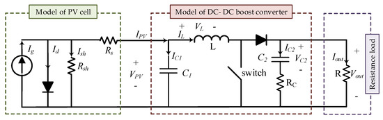
Figure 1.
Test system of this paper.
The DC-DC boost converter converts the PV’s low DC voltage to a high DC voltage based on the switching [33], and is modeled in (2):
where is the forward voltage of the diode, is the duty cycle, is the dynamic output resistance of the PV system, and is the control input. is related to the closed switch and results in the reverse-biased diode and is related to the open switch resulting in the forward-biased diode.The relationship between the voltage and current of a solar cell is nonlinear. Environmental factors such as solar radiation and ambient temperature change the cell’s MPP.
3. The Proposed Controller
The proposed control scheme of this paper consists of two loops. The first loop approximates the MPP and its voltage and current. This point (MPP) is the reference value of the second loop, which is the control loop.
3.1. Maximum Power Point
In our problem, PV voltage at MPP is considered as the reference voltage, , and PV current at MPP is chosen as the reference current, . The control goal is to keep the operating point of the PV system near the reference voltage. In some papers, such as [26], the reference voltage is determined by setting the derivative of the power of the PV system with respect to its current to zero in (3).
Evaluating from (1) and calculating its derivative with respect to , it can be stated as in (4)
By substituting (4) in (3), reference voltage, the voltage at MPP, is calculated as:
The reference current, current at MPP, has a linear relation with short circuit current according to [26]:
3.2. Backstepping SMC (BSMC)
SMC is one of the nonlinear control design procedures that applies a discontinuous control signal and changes the dynamics of a nonlinear system in a way that the system slides along a cross-section of the system’s ideal behavior.
The BSMC method is a recursive method that provides a link between the chosen Lyapunov function and the designed feedback controller to guarantee the global asymptotic stability of the closed loop system.
In this paper, the purpose of the controller design is to adjust the duty cycle of the DC-DC converter so that PV voltage, , tracks the reference voltage, . As a result, maximum power can be extracted from the PV system.
In [26], a BSMC was designed that provided an efficient control for MPPT of the PV system. The PV system can work close to MPP, tuning the duty cycle. Defining the tracking error, , and , the sliding surface, , is chosen as in (7)
In [26], the control input, , is as in (8).
where and are defined in (9):
Because of , the control signal is discontinuous and we have hard switching.
In [26], the dynamic of the sliding surface is defined as (10).
Asymptotic stability of the sliding surface and the convergence to reference voltage were ensured using the following Lyapunov function (11) as in [26]:
Similar to what was shown in [26], according to the Barbalat’s lemma for asymptotic stability of the closed loop system, the conditions (12) have to be satisfied:
where , , , and are the designed parameters.
3.3. Fuzzy Backstepping SMC (FBSMC)
In this paper, inspired by [32], to improve the performance of the controller mentioned above, in (16), the discontinuous sign function is replaced by the output of a fuzzy system (), and the controller is named FBSMC. The first fuzzy input is defined in (13).
where is the power variation and is the voltage variation of the PV panel in two consecutive sampling times, and . The second fuzzy input is E, changes in two consecutive sampling times, as defined in (14):
Similar to fuzzy PID controllers where the error and its variation (or its derivative) are considered as fuzzy inputs, here E and its variation in two consecutive time instants are considered inputs. The output of the fuzzy system is , which will be the substitution of the sgn() function in BSMC. Thus, the control input of fuzzy BSMC will be as follows:
Figure 2 shows the membership functions of the inputs and outputs of the fuzzy system. Figure 3 shows the configuration of the controlled PV system with the proposed controller. The outputs of the fuzzy rules are determined using PSO and are displayed in Table 2. The positive parameters , , and are the design parameters used to scale the inputs and outputs of the fuzzy system.
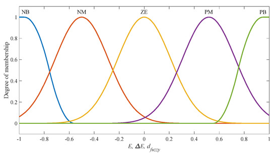
Figure 2.
Membership functions of the input and output of the fuzzy system.
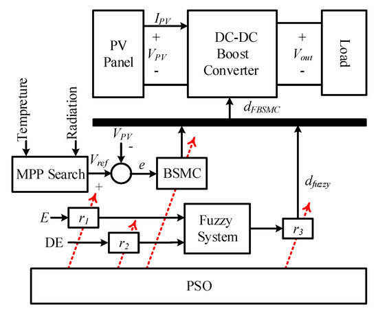
Figure 3.
Configuration of a PV system with the proposed controller.
Table 2.
Rules of the Fuzzy System.
3.4. PSO-Based Fuzzy Backstepping SMC (BSMC)
The design parameters of the BSMC, , and the parameters of the FBSMC, , are given in (16).
These parameters are optimized using PSO [34].
We are interested in using the maximum solar power, so we look for MPP. We control our PV panel such that the difference between PV power and power at MPP becomes minimum. This means that PV power becomes close to power at MPP, which is the maximum possible power of PV, . In other words, the PV power will become maximum. Therefore the mean of the absolute difference between the PV panel power and the maximum power is minimized as the objective function. The optimization problem is summarized in (17).
To summarize, PSO is used for the optimal determination of some parameters of the proposed controller that can be selected by trial and error. They are . Furthermore, the membership function for inputs and output of the fuzzy system are defined in the interval between −1 and 1. It is obvious that the interval for inputs and output affects the response. To address it we multiplied the inputs by and to bring the inputs to the interval between −1 and 1 and multiplied the output by to bring the output from the interval between −1 and 1 to the appropriate interval between and .
4. Case Study
The test system of this paper includes a PV module, a DC-DC boost converter, and a load resistance. Similar to [35], the PV module considered in this paper is KC200GH-2P, consisting of 54 series-connected polycrystalline cells. The simulation is implemented in a MATLAB environment. The electrical characteristics of this PV module are shown in Table 3 under standard conditions, that is, and solar radiation () of . The parameters of the DC-DC boost converter and resistance load are given in Table 4.
Table 3.
Electrical Specifications of KC200GH-2P PV Module in Standard Conditions.
Table 4.
DC-DC Boost Converter Parameters.
The MPP voltage is the reference input, which is calculated online.
4.1. Simulation Results
Simulation was performed for several scenarios:
Scenario 1 (Normal operating conditions): In this scenario, the temperature is and solar radiation is . Figure 4 compares the voltage, current, and power of the PV panel controlled with the BSMC [26], ABC-based PI control [31], and FBSMC. For rational comparison, the required parameters of all three controllers are optimized using PSO.
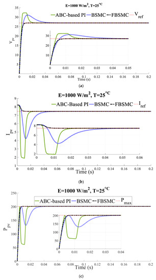
Figure 4.
(a) Voltage (b) current, (c) power of the controlled PV (Scenario 1).
The simulation results show approximately equal rise time and better transient response in terms of less settling time, less error between the reference values of the current and voltage, and more extracted power by applying the FBSMC approach compared to the other controllers. In other words, faster convergence to MPP is obtained using this controller. Applying the ABC-based PI control [16], the settling time becomes less than the BSMC [26], while the extracted power is less. The results are presented for 0.2 s. As the simulation results show, the transient state is less than 0.2 s, which demonstrates how fast the proposed controller can adapt itself and reach the steady state.
It is obvious that in the control problem transient state response is as important as steady state response. In this scenario all the controllers have almost the same steady state response and superiority of the controller proposed in this paper is shown in terms of the transient response and how fast and smoothly it reaches the steady state.
Scenario 2 (Constant Temperature and variable solar radiation): The temperature is equal to and the solar radiation increases linearly from at to at . Figure 5 compares the voltage, current, and power of the PV panel of the controlled system with the BSMC [26] and FBSMC.
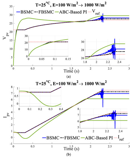
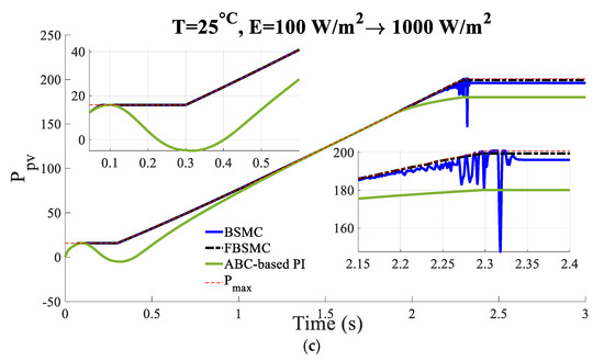
Figure 5.
(a) Voltage (b) current, (c) power of the controlled PV (Scenario 2).
The simulation results show that by applying the FBSMC approach in comparison to the other controllers, the MPP is tracked faster and more accurately. In other words, the best adaptation to the rapid variation in solar irradiation is obtained by this controller. The chattering phenomenon is eliminated using the fuzzy system in comparison to BSMC. Also, because of the nonlinear nature of the system, BSMC [26] as a nonlinear controller outperforms ABC-based PI control [31].
Simulations show that FBSMC has smoother behavior than BSMC while more power is gained. It demonstrates successful performance of the proposed controller using fuzzy.
Scenario 3 (Constant solar radiation and variable temperature): The solar radiation is equal to . The cell temperature increases from at linearly to at . Figure 6 compares the voltage, current, and power of the PV panel of the controlled system with the BSMC [26] and FBSMC.
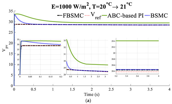
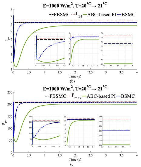
Figure 6.
(a) Voltage (b) current, (c) power of the controlled PV (Scenario 3).
The simulation results illustrate that a faster and more precise convergence to MPP and faster adaptation to temperature variation is obtained by applying the FBSMC compared to the BSMC.
Simulations show that FBSMC has faster and smoother behavior than others while more power is gained. It demonstrates the superiority of the proposed controller in terms of transient response.
Scenario 4 (Partial shading): Natural conditions or obstructions in the passage of irradiation result in partial shading. Under partial shading conditions, the sunlight reaches only part of a PV array. To simulate partial shading, two KC200GH-2P PV modules are connected in parallel, the temperature is equal to and the solar radiation for one of them is while for the other it is . Figure 7 compares the voltage, current, and power of the PV panel of the controlled system with the BSMC [26] and FBSMC.
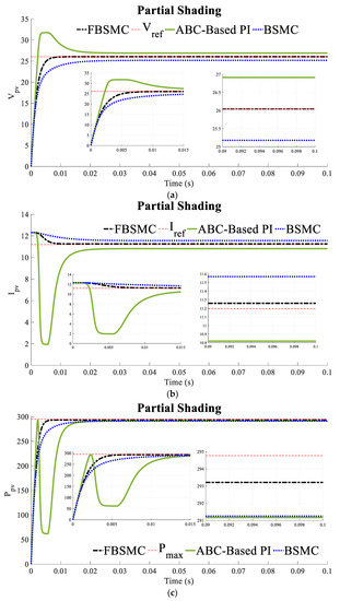
Figure 7.
(a) Voltage (b) current, (c) power of the controlled PV (Scenario 4).
Simulations show that FBSMC has the fastest adaption to environmental changes with a smooth trend while more power is gained.
Scenario 5 (Constant Temperature and variable solar radiation): The temperature is equal to and the solar radiation changes according to Figure 8. Figure 9 compares the voltage, current, and power of the PV panel of the controlled system with the BSMC [26] and FBSMC. Simulations demonstrate the superiority of FBSMC in terms of transient response while more power is gained.
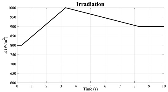
Figure 8.
Irradiation variation (Scenario 5).

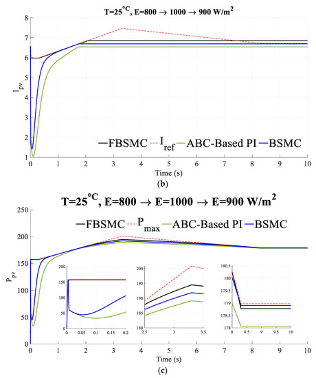
Figure 9.
(a) Voltage (b) current, (c) power of the controlled PV (Scenario 5).
The simulation results show that by applying the FBSMC approach in comparison to the other controllers, the MPP is tracked faster and more accurately. In other words, the best adaptation to the rapid variation in solar irradiation is obtained using this controller. The chattering phenomenon is eliminated, smoother behavior is achieved and transient response is improved using the fuzzy system in comparison to BSMC. Also, because of the nonlinear nature of the system, BSMC [26] as a nonlinear controller outperforms ABC-based PI control [31]. The superiority of FBSMC in particularly under partial shading conditions is demonstrated.
In all cases, in simulation time, the system passes its transient state and reaches its steady state. In other words, the settling time is less than the simulation time. This demonstrates how fast the proposed controller can respond to different changing situations.
4.2. Quantitative Analysis
To quantitatively evaluate the performance of the proposed control design, quantitative indices of the root mean square error between PV voltage and the reference voltage, , and the root mean square error between PV power and maximum power, are used as follows, respectively:
The dynamic efficiency () is calculated using the following equation as in [36]:
The above-mentioned quantitative indices, mean power, , and settling time are compared for the controlled system with the FBSMC, BSMC [26], and ABC-based PI control [31] in Table 5.
Table 5.
Quantitative Evaluation of Performance.
In all scenarios, FBSMC outperforms the others in terms of the extracted power and dynamic efficiency. The power extracted using BSMC is more than that of ABC-based PI control. In the first scenario, the settling time decreases using BSMC, and the fuzzy system, respectively. In the second and third scenarios, where the climate condition changes rapidly, the ABC-based PI control cannot track MPP, as well as the others, and errors increase dramatically.
4.3. Robustness Evaluation
To evaluate the robustness as the performance of the controller under normal operating conditions, variations in the resistance load,, and parameters of DC-DC converter components including capacitor capacitance, , and inductance of the inductor, , are considered. Figure 10 and Figure 11 show the PV power for a 20% increase and a 20% decrease in the above-mentioned parameters, respectively. Table 6 and Table 7 compare dynamic efficiency applying the BSMC [26] and the FBSMC for a 20% increase and a 20% decrease in the parameters mentioned above. The results demonstrate the robust performance of BSMC and FBSMC while ABC-based PI control is not robust. Despite the substantial changes in the parameters, the FBSMC maintains its superiority over the others and has a lower variation percent in power extracted, which verifies its robust performance.
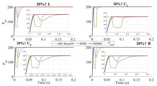
Figure 10.
Extracted PV power for a 20% increase in the system parameters.
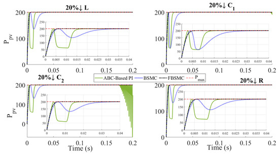
Figure 11.
Extracted PV power for a 20% decrease in the system parameters.
Table 6.
Dynamic efficiency for a 20% increase in the system parameters.
Table 7.
Dynamic efficiency for a 20% decrease in the system parameters.
It is vital that combining three methods, in spite of improving its performance, increases the complexity of the proposed method which in turn makes its real implementation challenging, although tracking MPP in a smooth manner in variable environmental conditions is motivating. In other words, for real implementation the tradeoff between better performance and adaption with complexity have to be considered.
5. Conclusions
A PV system including a PV module, DC-DC boost converter, and resistive load was used in this paper. Due to the nonlinearity of the I–V characteristics of the PV module, the SMC was considered for the MPPT strategy to increase the efficiency of solar panels under rapidly changing atmospheric conditions. This paper proposed a Backstepping SMC that ensured system stability using Lyapunov criteria. The output of a fuzzy inference system replaced the saturation function, and a modified SMC was used for MPPT to ensure smooth behavior. The derivative of PV power with respect to its current was set equal to zero, and the MPP voltage was chosen as the reference voltage to determine MPP. The proposed fuzzy BSMC (FBSMC) parameters were optimized using the PSO approach. The optimization objective was to minimize the mean of the absolute difference between PV power and the maximum power. The proposed controller as tested in various case studies on account of MPP’s dependence on temperature and solar radiation. The simulation results show that shorter settling time, small error, and enhanced power extraction capability are achieved by applying the PSO-based FBSMC approach compared to the conventional BSMC. Moreover, the proposed approach provides faster adaptation to temperature and solar radiation variations, ensuring faster convergence to the MPP compared to the BSMC and ABC-PI controller presented in previous research. To quantitatively evaluate the performance of the proposed control design, quantitative indices of the root mean square error between PV voltage and the reference voltage, the root mean square error between PV power and maximum power, and the dynamic efficiency were used. Finally, the robustness of the proposed controller was validated by providing variation within the system components.
Using other optimization algorithms, especially novel ones, to determine design variables is suggested for future research.
Author Contributions
Conceptualization, M.R.S.; Methodology, F.J. and M.R.S.; Software, F.J.; Formal analysis, F.J. and M.R.S.; Investigation, F.J. and M.R.S.; Resources, F.J.; Data curation, F.J. and R.Y.; Writing – original draft, F.J.; Writing – review & editing, M.R.S., B.A. and V.J.; Supervision, M.R.S.; Project administration, M.R.S.; Funding acquisition, B.A. All authors have read and agreed to the published version of the manuscript.
Funding
This research received no external funding.
Data Availability Statement
Not applicable.
Conflicts of Interest
The authors declare no conflict of interest.
References
- Raugei, M.; Leccisi, E.; Azzopardi, B.; Jones, C.; Gilbert, P.; Zhang, L.; Zhou, Y.; Mander, S.; Mancarella, P. A multi-disciplinary analysis of UK grid mix scenarios with large-scale PV deployment. Energy Policy 2018, 114, 51–62. [Google Scholar] [CrossRef]
- Azzopardi, B.; Mutale, J. Life cycle analysis for future photovoltaic systems using hybrid solar cells. Renew. Sustain. Energy Rev. 2010, 14, 1130–1134. [Google Scholar] [CrossRef]
- Ko, J.-S.; Huh, J.-H.; Kim, J.-C. Overview of Maximum Power Point Tracking Methods for PV System in Micro Grid. Electronics 2020, 9, 816. [Google Scholar] [CrossRef]
- Tse, K.K.; Chung, H.S.H.; Hui, S.Y.R.; Mok, C.M.; Ho, M.T. A Novel Maximum Power Point Tracking Technique for PV Panels. In Proceedings of the 2001 IEEE 32nd Annual Power Electronics Specialists Conference, PESC, Vancouver, BC, Canada, 17–21 June 2001; Volume 4, pp. 1970–1975. [Google Scholar]
- Hart, G.W.; Branz, H.M.; Cox, C.H. Experimental tests of open loop maximum-power-point tracking techniques. Sol. Cells 1984, 13, 185–195. [Google Scholar] [CrossRef]
- Noguchi, T.; Togashi, S.; Nakamoto, R. Short-Current Pulse Based Adaptive Maximum-Power-Point Tracking for Photovoltaic Power Generation System. In Proceedings of the 2000 IEEE International Symposium on Industrial Electronics, Cholula, Mexico, 4–8 December 2000; pp. 157–162. [Google Scholar]
- Narendiran, S. Grid Tie Inverter and MPPT—A Review. In Proceedings of the 2013 International Conference on Circuits, Power and Computing Technologies (ICCPCT), Nagercoil, India, 20–21 March 2013; pp. 564–567. [Google Scholar]
- Liu, B.; Duan, S.; Liu, F.; Xu, P. Analysis and Improvement of a Maximum Power Point Tracking Algorithm Based on Incremental Conductance Method for Photovoltaic Array. In Proceedings of the 2007 7th International Conference on Power Electronics and Drive Systems, Bangkok, Thailand, 27–30 November 2007; pp. 637–641. [Google Scholar]
- Wilamowski, B.M.; Li, X. Fuzzy System Based Maximum Power Point Tracking for PV System. In Proceedings of the 28th Annual Conference of the Industrial Electronics Society, Sevilla, Spain, 5–8 November 2002; pp. 3280–3284. [Google Scholar]
- Di Piazza, M.C.; Pucci, M.; Ragusa, A.; Vitale, G. Analytical versus neural real-time simulation of a photovoltaic generator based on a DC-DC converter. IEEE Trans. Ind. Appl. 2010, 46, 2501–2510. [Google Scholar] [CrossRef]
- Gomez, J.M.; Shanmugam, P.K. Flexible Power Point Tracking Using a Neural Network for Power Reserve Control in a Grid-Connected PV System. Energies 2022, 15, 8234. [Google Scholar] [CrossRef]
- Al-Majidi, S.D.; Abbod, M.F.; Al-Raweshidy, H.S. A Modified P&O-MPPT based on Pythagorean Theorem and CV-MPPT for PV Systems. In Proceedings of the 2018 53rd International Universities Power Engineering Conference (UPEC), Glasgow, UK, 4–7 September 2018; pp. 1–6. [Google Scholar]
- Kim, J.-C.; Huh, J.-H.; Ko, J.-S. Improvement of MPPT control performance using fuzzy control and VGPI in the PV system for micro grid. Sustainability 2019, 11, 5891. [Google Scholar] [CrossRef]
- Manoharan, P.; Subramaniam, U.; Babu, T.S.; Padmanaban, S.; Holm-Nielsen, J.B.H.; Mitolo, M.; Ravichandaran, S. Improved perturb and observation maximum power point tracking technique for solar photovoltaic power generation systems. IEEE Syst. J. 2020, 15, 3024–3035. [Google Scholar] [CrossRef]
- Satapathy, S.S.; Kumar, N. Framework of maximum power point tracking for solar PV panel using WSPS technique. IET Renew. Power Gener. 2020, 14, 1668–1676. [Google Scholar] [CrossRef]
- Gunasekaran, M.; Krishnasamy, V.; Selvam, S.; Almakhles, D.J.; Anglani, N. An adaptive resistance perturbation based MPPT algorithm for photovoltaic applications. IEEE Access 2020, 8, 196890–196901. [Google Scholar] [CrossRef]
- Jately, V.; Azzopardi, B.; Joshi, J.; Venkateswaran, V.B.; Sharma, A.; Arora, S. Experimental Analysis of hill-climbing MPPT algorithms under low irradiance levels. Renew. Sustain. Energy Rev. 2021, 150, 111467. [Google Scholar] [CrossRef]
- Jately, V.; Arora, S. Performance Investigation of Hill-Climbing MPPT Techniques for PV Systems Under Rapidly Changing Environment. In Intelligent Communication, Control and Devices. Advances in Intelligent Systems and Computing; Singh, R., Choudhury, S., Gehlot, A., Eds.; Springer: Singapore, 2018; Volume 624. [Google Scholar] [CrossRef]
- Jately, V.; Arora, S. An Efficient Hill-Climbing Technique for Peak Power Tracking of Photovoltaic Systems. In Proceedings of the 2016 IEEE 7th Power India International Conference (PIICON), Bikaner, India, 25–27 November 2016; pp. 1–5. [Google Scholar] [CrossRef]
- Sharma, A.; Sharma, A.; Jately, V.; Averbukh, M.; Rajput, S.; Azzopardi, B. A Novel TSA-PSO Based Hybrid Algorithm for GMPP Tracking under Partial Shading Conditions. Energies 2022, 15, 3164. [Google Scholar] [CrossRef]
- Ahmad, F.F.; Ghenai, C.; Hamid, A.K.; Bettayeb, M. Application of sliding mode control for maximum power point tracking of solar photovoltaic systems: A comprehensive review. Annu. Rev. Control 2020, 49, 173–196. [Google Scholar] [CrossRef]
- Garraoui, R.; Barambones, O.; Hamed, M.; Lassaad, S. Real-time implementation of a maximum power point tracking algorithm based on first order sliding mode strategy for photovoltaic power systems. Trans. Inst. Meas. Control 2018, 40, 1499–1509. [Google Scholar] [CrossRef]
- Farhadi, P.; Sedaghat, M.; Sharifi, S.; Taheri, B. Power Point Tracking In Photovoltaic Systems by Sliding Mode Control. In Proceedings of the 2017 10th International Symposium on Advanced Topics in Electrical Engineering (ATEE), Bucharest, Romania, 23–25 March 2017. [Google Scholar]
- Zhao, T.; Ji, N.; Xu, H.; Zhang, T. Study on Variable Step Sliding-Mode Based MPPT for PV Array. In Proceedings of the 2019 14th IEEE Conference on Industrial Electronics and Applications (ICIEA), Xi’an, China, 19–21 June 2019. [Google Scholar]
- Naghmash; Armghan, H.; Ahmad, I.; Armghan, A.; Khan, S.; Arsalan, M. Backstepping based non-linear control for maximum power point tracking in photovoltaic system. Sol. Energy 2018, 159, 134–141. [Google Scholar] [CrossRef]
- Dahech, K.; Allouche, M.; Damak, T.; Tadeo, F. Backstepping sliding mode control for maximum power point tracking of a photovoltaic system. Electr. Power Syst. Res. 2017, 143, 182–188. [Google Scholar] [CrossRef]
- Shahdadi, A.; Barakati, S.M.; Khajeh, A. Design and implementation of an improved sliding mode controller for maximum power point tracking in a SEPIC based on PV system. Eng. Rep. 2019, 1, e12042. [Google Scholar] [CrossRef]
- Bjaoui, M.; Khiari, B.; Benadli, R.; Memni, M.; Sellami, A. Practical Implementation of the Backstepping Sliding Mode Controller MPPT for a PV-Storage Application. Energies 2019, 12, 3539. [Google Scholar] [CrossRef]
- Harrag, A.; Messalti, S. PSO-based SMC variable step size P&O MPPT controller for PV systems under fast changing atmospheric conditions. Int. J. Numer. Model. Electron. Netw. Devices Fields 2019, 32, e2603. [Google Scholar] [CrossRef]
- Tightiz, L.; Mansouri, S.; Zishan, F.; Yoo, J.; Shafaghatian, N. Maximum Power Point Tracking for Photovoltaic Systems Operating under Partially Shaded Conditions Using SALP Swarm Algorithm. Energies 2022, 15, 8210. [Google Scholar] [CrossRef]
- Shamsoddini, F. Maximum Power Point Tracking of Photovoltaic. Master’s Thesis, Shahid Bahonar University of Kerman, Kerman, Iran, 2015. [Google Scholar]
- Bounechba, H.; Bouzid, A.; Nabti, K.; Benalla, H. Comparison of perturb & observe and fuzzy logic in maximum power point tracker for PV systems. Energy Procedia 2014, 50, 677–684. [Google Scholar] [CrossRef]
- Jamshidi, F.; Emamzadehei, S.L.; Ghanbarian, M.M. Using fuzzy PI controller optimized by PSO for frequency control of island microgrids. J. Soft Comput. Inf. Technol. 2017, 6, 36–43. [Google Scholar]
- Delavari, H.; Rashidnejad Heydari, S.Z. Fractional order Adaptive Terminal Sliding Mode Controller Design for MPPT in a Solar Cell under Normal and Partial Shading Condition. J. Nonlinear Syst. Electr. Eng. 2019, 5, 4–22. [Google Scholar]
- González-Castaño, C.; Restrepo, C.; Kouro, S.; Rodriguez, J. MPPT Algorithm Based on Artificial Bee Colony for PV System. IEEE Access 2021, 9, 43121–43133. [Google Scholar] [CrossRef]
- Jately, V.; Bhattacharya, S.; Azzopardi, B.; Montgareuil, A.G.; Joshi, J.; Arora, S. Voltage and Current Reference Based MPPT under Rapidly Changing Irradiance and Load Resistance. IEEE Trans. Energy Convers. 2021, 36, 2297–2309. [Google Scholar] [CrossRef]
Disclaimer/Publisher’s Note: The statements, opinions and data contained in all publications are solely those of the individual author(s) and contributor(s) and not of MDPI and/or the editor(s). MDPI and/or the editor(s) disclaim responsibility for any injury to people or property resulting from any ideas, methods, instructions or products referred to in the content. |
© 2023 by the authors. Licensee MDPI, Basel, Switzerland. This article is an open access article distributed under the terms and conditions of the Creative Commons Attribution (CC BY) license (https://creativecommons.org/licenses/by/4.0/).