Article

Oscillation Damping Neuro-Based Controllers Augmented Solar Energy Penetration Management of Power System Stability

1
Electrical Engineering Department, Assiut University, Assiut 71516, Egypt
2
Department of Electrical Engineering, Ural Federal University, 620002 Yekaterinburg, Russia
3
Faculty of Engineering and Technology, Future University in Egypt, Cairo 11835, Egypt
4
Department of Smart City & Energy, Gachon University, Seongnam 13120, Republic of Korea
*
Authors to whom correspondence should be addressed.
Energies 2023, 16(5), 2391; https://doi.org/10.3390/en16052391
Submission received: 30 January 2023 / Revised: 18 February 2023 / Accepted: 27 February 2023 / Published: 2 March 2023

Abstract

:
The appropriate design of the power oscillation damping controllers guarantees that distributed energy resources and sustainable smart grids deliver excellent service subjected to big data for planned maintenance of renewable energy. Therefore, the main target of this study is to suppress the low-frequency oscillations due to disruptive faults and heavy load disturbance conditions. The considered power system comprises two interconnected hydroelectric areas with heavy solar energy penetrations, severely impacting the power system stabilizers. When associated with appropriate controllers, FACTs technology such as the static synchronous series compensator provides efficient dampening of the adverse power frequency oscillations. First, a two-area power system with heavy solar energy penetration is implemented. Second, two neuro-based controllers are developed. The first controller is constructed with an optimized particle swarm optimization (PSO) based neural network, while the second is created with the adaptive neuro-fuzzy. An energy management approach is developed to lessen the risky impact of the injected solar energy upon the rotor speed deviations of the synchronous generator. The obtained results are impartially compared with a lead-lag compensator. The obtained results demonstrate that the developed PSO-based neural network controller outperforms the other controllers in terms of execution time and the system performance indices. Solar energy penetrations temporarily influence the electrical power produced by the synchronous generators, which slow down for uncomfortably lengthy intervals for solar energy injection greater than 0.5 pu.

1. Introduction

1.1. Motivation

Recently, many researchers worldwide have been working to reduce the impact of disruptive faults within power systems as a result of the increased penetration of distributed energy resources (DERs). The goal is to efficiently capture data and transform it into insightful learnings that boost productivity, efficiency, and stability. However, power systems have a variety of features that make control algorithms impractical for heavy amounts of renewable energy penetration [1]. The concerns of such features include: (i) a modern power system’s stability is most at risk from power system oscillations, especially given how heavily distributed energy resources are used today and how close to their transient and steady-state stability limitations they operate [2]; (ii) renewable energy sources (RESs) are frequently used in distributed networks and even at the level of microgrids, but they lack any type of power system stabilizer (PSS) or governor-like device besides they are fundamentally intermittent and unreliable; (iii) future control must be developed due to the increasing complexity of power system interconnections compounded by load variations, high voltage DC, and high voltage AC systems [3]; (iv) power systems can operate as standalone systems or in conjunction with multiple microgrids, which might alter the inertia of the entire system and, as a result, the rotor speed and frequency of traditional synchronous generators [4].
Accordingly, the authors of this research are encouraged to propose artificial intelligence neuro-based effective controllers for manipulating all concerns to dampen the power frequency oscillation on the synchronous machine connected with photovoltaic systems. Likewise, because the suggested method is based on learning, it should be robust to many types of parameter uncertainty. As a result, the suggested method greatly improves the rotor speed profile, ensuring long-term stability.

1.2. Related Work

When the electrical energy flows from a producing station to a consumer, it is frequently susceptible to oscillation. These oscillations might occur as a result of load variations or any disruptive faults through the transmission, making power system stability within power systems a key research topic. Whenever disruptive faults develop, low-frequency oscillations ensue in the power system. Flexible AC Transmission System (FACTS) controllers are thus being used as a result of the recent advancements in the electronics industry to remedy power oscillations against such disruptive faults.
Several studies have been undertaken in the literature to address the frequency damping controller design procedures. In [5], a review focusing on fractional order PID to improve the stability of FACTS-based inverters, with the recommendation that the developed controller may operate more efficiently than traditional PI controllers. In another article [6], the modeling of an on-grid solar PV was conducted where the droop controlling was added to enhance the classic PI controllers. The authors of [6] concluded that the total harmonic distortion of 5% could be obtained. In [7], an ANFIS enhanced by a PSO controller was introduced to dampen the low-frequency oscillation in power systems, with the conclusion that the ANFIS controller would have significant potential to be deployed and tested in several power systems. Low inertia networks were recently studied in [8], where it was found that by carefully adjusting the controller’s parameters, the network frequency oscillation caused by low inertia might well be reduced. A comprehensive review of low-frequency oscillation with the help of photovoltaic was introduced in [9] with conclusions that there would be severe issues if there are a huge number of on-grid converters. Such findings pave the way for artificially based optimal controllers. In [10], to reduce frequency oscillation through microgrids, hardware-in-the-loop validation of a deterministic controller was performed using JAYA, with the conclusion that a new controller design is required to suppress response deviations. In [11], an adaptive neuro fuzzy-based controller to suppress the frequency oscillation of an on-grid synchronous machine under several fault conditions. The authors of [11] concluded that the learning-based controllers outperformed in terms of the system indices. Via several deterministic optimizers, a PI-based controller was developed to produce the optimal power flow of the DC/DC converter [12]. Similar investigations were conducted in [13] using the fractional order PI controller. The results obtained in [12,13] demonstrate that more artificial intelligence controllers might be an open area for controller design. In [14], the modeling of a wind energy-based doubly fed induction generator in association with a synchronous machine was investigated, where a controller via the LQG and an observer via Kalman were designed; however, the fault conditions and the transmission lines’ incorporation were ignored. The authors of [15] utilized the fractional order the proportional-derivative controller to suppress the frequency oscillation of interconnected power systems, however, fault analysis was not considered. In [16], similar research was carried out by installing an on-grid wind unit in one of the electricity system’s areas. An improved analysis was conducted in [17] by developing a model for the PV module in the load/frequency study. However, the frequency brought on by system inertia problems was disregarded [15,17].
In the literature, it has been demonstrated that FACTs are useful for reducing oscillations in the power system. In [18], a static synchronous series compensator (SSSC) was investigated via the Hamiltonian theory. Yet, the design techniques for such nonlinear controllers necessitate rigorous power system development, which adds to the power system complexity. In [19], a neuro-based sliding mode controller for the SSSC device was introduced via the Lyapunov theorem. The learning-based design in [19] simplifies the states of the nonlinear system. In [20], solar photovoltaic panels (PVs) were tested in conjunction with a power system stabilizer using STATCOM technology, and it was found that the PVs could improve the power system oscillation damping. Similarly, comparable research was reported in [21], with the result that evaluating the capability curves might help an on-grid system coordinate its active and reactive power more adequately. Another paper [22] demonstrated inter-area oscillation suppression employing FACTS devices, with a 41.7% active power loss reduction with SSSC against 29.3% using STATCOM technology. In [7], the power oscillation damping was conducted through the ANFIS-based machine learning approach using a unified power flow controller, which belongs to the FACTs technology with conclusions that the ANFIS-optimized PSO could improve the power system real-time stability. In [23], the SSSC technology remarkably improved the power system stabilizer and thus the low-frequency power oscillations. The authors of [24] present PI and fuzzy control systems based on DSTATCOM technology, concluding that current artificial intelligence controllers are promising. In [25], the rotor speed deviation of the synchronous generator was investigated using the sine-cosine algorithm to create the SSSC lead-lag compensator and power system stabilizer (PSS). The results obtained in [25] demonstrated that the developed sine-cosine optimizer had outperformed the other heuristic optimizers. In another research [26], a comparison between the STATCOM and SVC technologies based on fuzzy-based controller design to improve the power system with wind farm stability was conducted. Another study [26] compared the STATCOM and SVC technologies for improving the power system stability with wind farms using fuzzy-based controller design with results that the STATCOM-based fuzzy controllers quickly were able to remedy the faults compared to the SVC-based fuzzy controller.
In [27], the harris hawks optimizer was utilized to stabilize an interconnected wind farm. The authors of [27] treat the wind farm as a classic power system area with synchronous generators, which was uncommon. In [28], the stability of an on-grid wind farm power system was recently enhanced via the static VAR compensator, which is one of the FACTS’ technologies under extreme fault conditions. The findings in [28] supported the suggested SVC strategy’s capacity to adjust voltage deviations and improve voltage stability. In [29], STATCOM technology was used to discuss the stability issues of an on-grid doubly fed induction generator wind farm during faults. A fuzzy logic controller for the STATCOM was suggested since the protective mechanism inhibits rotor side converter functioning. In another research [30], fuzzy-based controllers for the SSSC technology and the power system stabilizers were conducted with conclusions that the learning-based controllers were recommended. In [31], a fuzzy-neural-based SSSC was proposed to suppress the oscillation of a power system with a wind farm with results the learning rate could be significantly reduced, which highlights the utilization of the learning-based artificial intelligence controllers. A review of the artificial intelligence controllers’ expected challenges at the level of smart grids was conducted in [32] with conclusions that the use of artificial intelligence will have become more vital in guaranteeing the secure and reliable functioning of smart grids. The neuro-fuzzy-based controller for the STATCOM technology was investigated in [33], concluding that such controllers for multi-machine power systems will be attractive. The utilization of the dynamic voltage restorers with the integration of RESs was considered in [34] with results that the total harmonic distortion was reduced by 4%. In [35], a hybrid power system stabilizer and SSSC controller was designed, concluding that a meta-heuristic algorithm other than the genetic algorithm could be used to enhance the power frequency oscillations. In [36], a fuzzy lead-lag compensator for SSSC and the power system stabilizer structure was introduced via the whale optimization algorithm, concluding that the coordinated controller remarkably suppresses the power system oscillations. In [37], with penetrations of both wind and solar PVs for a distributed network, the oscillation damping was conducted using the power system stabilizer and battery energy storage system. The wind farm, consisting of both squirrel cage and doubly fed induction generators, was integrated into the conventional power system in [38]. Artificial neural networks were used to create power system controllers utilizing SSSC technology, and the findings showed that they outperformed traditional controllers. In another study [39], the neuro-fuzzy-based wavelet controller for SSSC technology was investigated. A similar investigation was carried out in [40] with a multi-machine system, concluding that such an artificial intelligence controller had significantly enhanced the transient stability of a single machine connected to an infinite bus system. In [41], several objective functions were used to design both a power system stabilizer and the SSSC controller via the seeker optimizer, whereby a four-machine test system was investigated, concluding that the optimization scheme improved the system’s stability and suppressed the power oscillations. The electromechanical deviations at the level of microgrids were investigated in [42], in which both the 9-bus and the 33-bus systems were tested, concluding that the reduced energy production from the conventional synchronous generators would improve the system stability which seems unrealistic.
The game theory and fuzzy logic approaches have been used recently in [43] to address the customer’s preferences based on home appliances scheduling framework while taking into account a variety of constraints and demand response. The key findings in [43] averred that the proposed approach would decrease the overall costs for both the electrical and thermal loads. Similar results were found in [44] by combining the “grey wolf” and “crow search” algorithms. In [45], the demand response for smart grid issues was investigated wherein reprogramming the consumers’ product operation resulted in significant cost reduction. Due to the use of hydrophilic material, significant gains in PV efficiency were realized in [46]. Researchers used thermal PV systems in a subsequent study to enhance the voltage profiles within connected microgrids [47]. The transient impact on the synchronous generator, however, was not considered [43,44,45,46,47].

1.3. Contribution

Recent developments lead to an increasingly scattered world where information and communication technologies must be used to regulate, balance, and harness the potential of solar power generation and distribution over a wide range of production points. The study’s main goals are to
  • Develop two neuro-based controllers to dampen the low-frequency oscillation of the conventional synchronous generators within distributed networks.
  • Construct a PV solar energy management strategy to diminish the solar energy’s major impact on the rotor speed and rotor angle of the neighboring synchronous generators.
FACTS are used in conjunction with power system stabilizers (PSS) to mitigate electro-mechanical power system oscillations due to disruptive faults conditions. The concerns become more severe with the integration of RESs within microgrids. The investigation of the above approaches reveals that (i) the integration of modern RESs at the level of microgrids with severe disruptive faults is rare, (ii) some approaches utilized exhaustive optimizations methods, which complicates the design procedures, (iii) others were interested in load/frequency analysis, which was not taken into account by either FACTS technology or the power system electromechanical oscillations, (iv) Furthermore, to account for the significant penetrations of the solar PV, further research is still required for the learning base artificial intelligence controller. The use of an artificial intelligence controller with a learning framework seeks to reduce the distributed networks’ traditional synchronous generators’ rotor speed and rotor angle deviations. Accordingly, this study contributes to the literature as:
  • Developing a deep neural network-based controller for the SSSC technology to help the PSS and reduce the power system electromechanical oscillations. Since the proposed approach is learning-based, it avoids the nonlinear complexity associated with modern power systems and is considered straightforward yet effective.
  • The particle swarm optimization (PSO), which has a high exploitation feature is employed to obtain the optimal numbers of the hidden layers as well as the number of neurons for each layer.
  • Implementation of a two-area power system with heavy solar energy penetration in phasor form. Accordingly, an adopted modified PV energy management strategy is developed.
  • A fair comparison with the lead-lag and the Matlab/Simulink neuro-fuzzy-based controllers is made to prove the usefulness of the created neuro-based controllers.
An impartial comparison is made between the developed controllers, focusing mainly on the execution time and the merit of the control effort. The control effort is the controller’s output signal, which is finally translated at the inverter side as a PWM signal. Phasor modeling for solar PV is used, which was collected from the literature, to take into consideration how the penetration of solar energy affects the rotor speed and rotor angle deviations of conventional synchronous generators during both disruptive faults and severe load changes. To confirm the robustness of the controllers, other performance indices, such as the integral squared error, are used. The controller that reduces the performance indices while exerting sufficient control effort is more satisfying.

1.4. Paper Organization

The following is the order in which this work is organized: after the introduction, the problem description section is handled. In Section 3, we will talk about how to formulate the problem. In Section 4 and Section 5, the results and discussions are presented, followed by the conclusions.

2. System under Study and Problem Description

The examined microgrid is depicted in Figure 1. The testing system architecture is made up of two buses, labeled B1 and B2, and two major transmission lines drawn simply by the horizontal lines. The power system includes three transformers, two synchronous generators labeled G1 and G2, respectively, and three resistive loads and a high-rate inductive load. The idea is to efficiently gather data and transform it into insightful knowledge that boosts stability and productivity. Accordingly, through an inverter and transformer, solar PV is linked to bus B1. The linked microgrid receives electrical energy from the solar PV system, which follows the frequency of the generator G1. The generator G1 and the solar PV are considered one DERs where the energy supplied by the latter resource influences both the conventional generator rotor speed and rotor angles. With the loads spread as illustrated in Figure 1, the SSSC technology can provide the necessary reactive power during disruptive failures that occur at the tie lines, while also improving the transient stability of both generators. The key finding is thus to design a robust controller, which optimally operates the SSSC technology. Accordingly, the modeling of the hybrid microgrid components and the developed controllers are explored in the following subsections. The system data is in the Appendix A and Appendix B.

2.1. Two-Area Power System Modeling

Excluding the solar PV from the microgrid depicted in Figure 1, the modeling of individual components is given in [48]. The SSSC, one of the important FACTS devices, is employed for power oscillation damping in this application. In this study, the two-area system is modified by incorporating solar PV as a DER. Two power generation substations and one large load center, situated at bus B3, as well as the transmission lines make up the power grid. The first power generation substation (G1) has a 2100 MVA rating, whereas the second (G2) has a 1400 MVA rating. Each generating unit has a hydraulic turbine and a PSS. The SSSC has a current rating of 100MVA and can inject up to 10% of the normal system voltage.

2.2. Developed Controllers Modeling

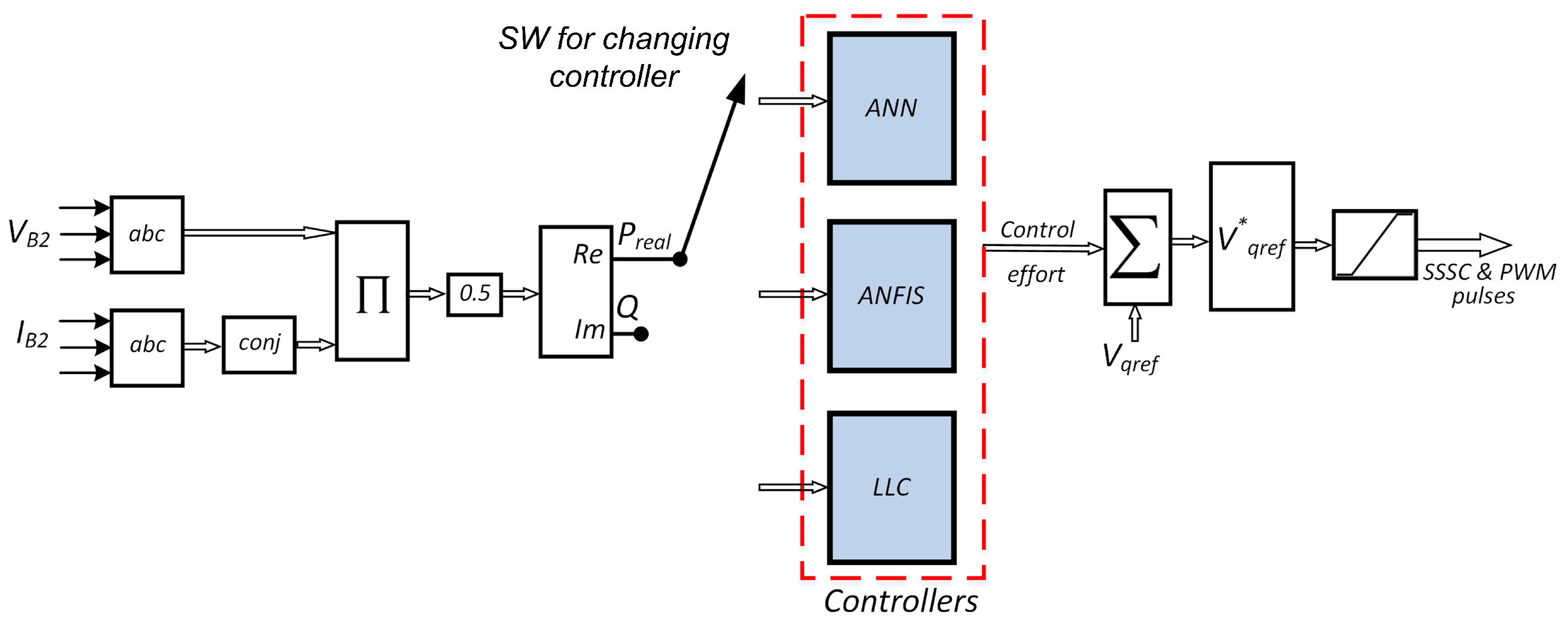
The power oscillation damping of the system is verified by designing robust controllers of the SSSC device, which operates a “typical three-level PWM SSSC” inverter [48]. The voltages and currents at bus 2 are sensed wherein the active power is calculated, filtered, and fed to the developed controllers as demonstrated in Figure 2. The three controllers do not work together simultaneously. The switch (SW) connection in Figure 2 determines how they operate. Herein, the output signal is called the control effort, which is then added to the q-axis voltage components, and via the limiter block, the PWM signal is obtained. In the following subsections, the developed controllers are explained.

2.2.1. Deep Neural Networks Controller

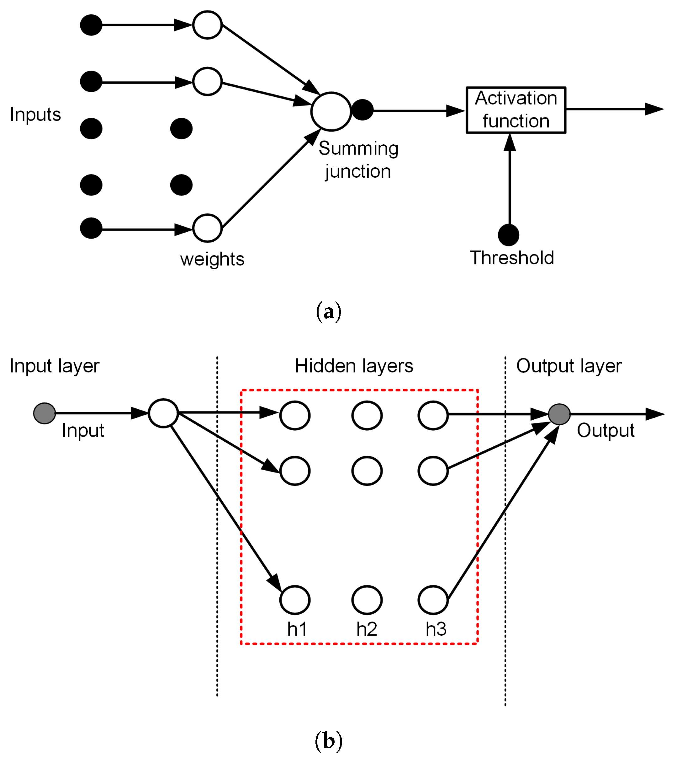
Artificial neural networks (ANN) have recently been utilized to solve several engineering problems [49,50]. Yet, nature-inspired algorithms, such as genetic algorithms, have to be used to acquire the optimal weights [51]. An ANN is made up of three layers: input, hidden layers, and output layers, each of which is processed by several neurons. Signals can pass via one or more hidden layers from the input layer to the output layer. The connections with weights are used to transport the signals. Activations are used to the input signal to produce the output regression or trained signal. Figure 3a depicts a basic artificial neuron construction.
The ANN is considered shallow if there is only one hidden layer. The input neurons provide a signal to each neuron in the hidden layers. The more hidden layers, the ANN is thus termed deep as shown in Figure 3b. The key findings in this study are to determine the optimal number of hidden layers and the corresponding number of neurons in each.

2.2.2. Adaptive Neuro-Fuzzy (ANFIS) Controller

The advantages of fuzzy and the flexibility of ANN are combined in ANFIS. The ANFIS technique is used to train Sugeno-type fuzzy systems that must adhere to the following constraints: [49,52]:
  • The fuzzy system is of the first-order Sugeno-type.
  • The weighted average defuzzification step produces a single output.
  • Each rule carries the same weight as one.
  • The AND logic is expressed as a prod, the OR logic is represented by max, the implication is represented by prod, and aggregation is represented by max.
The user would give the ANFIS with the number of membership functions for each input and output, the kind of membership functions, the dimensionality of training and checking data, and the optimization criterion for lowering the measured error. The number of squared differences between the actual and estimated curves is usually used to establish the optimization criterion [53].

2.2.3. Lead-Lag Compensator

The SSSC comprises a low-pass filter, a washout high-pass filter, and a lead-lag compensator (LLC). LLC implementation is tailored in [48]. Herein, the transfer function of the LLC is given in Equation (1), in which s is Laplace’s operator.
F ( s ) = K c 1 + s T 1 1 + s α T 1 1 + s T 2 1 + s β T 2

2.3. Solar PV Energy Management System

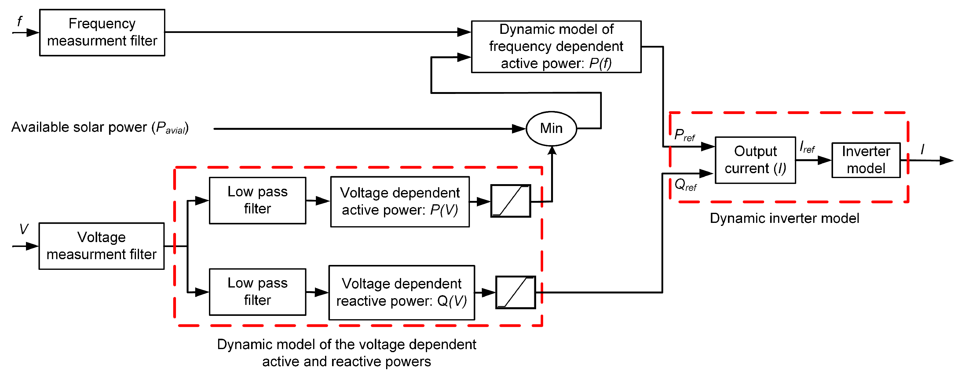
This study’s main objective is to address the major effect that solar PV has on the synchronous generators’ rotor speed and rotor angle, which in turn affects the utility grid’s frequency. Therefore, the PV penetration is managed via an energy management system. The investigation of the dynamic behavior the solar PV systems at low voltage levels is crucial. Solar PV tracks the adjacent area frequency while injecting actual power into it, affecting the system area frequency and generator rotor speed as a consequence. The phasor model described in [54] is thus adopted in this study. The PV generator is implemented as part of the whole two-area phasor model. Consequently, the voltage (V) and the frequency (f) are the inputs, while the injected current (I) is the solar PV output as illustrated in Figure 4. The active power set-point (P r e f ) of the inverter is determined using the frequency-dependent active power model, in which the function P ( f ) is given as in Equation (2).
P ( f ) = 0 : f 57.5 P m i n : 57.5 < f < 60.2 P m i n 0.4 P m i n ( f 60.2 ) : 60.2 < f < 61.5 0 : f > 61.5
The P r e f , shown in Figure 4, is designated P m i n and determined by choosing the minimum value according to Equation (3).
P m i n = m i n ( P a v a i l , P ( V ) )
where P a v a i l is the available solar PV modules power. The voltage-dependent function P ( V ) is given in Equation (4).
P ( V ) = P 1 : V 0.93 P 2 P 1 V 2 V 1 + P 2 V 2 P 2 P 1 V 2 V 1 : 0.93 < V < 0.97 P 2 : 0.97 < V < 1.03 P 3 P 2 V 3 V 2 + P 3 V 4 P 3 P 2 V 3 V 2 : 1.03 < V < 1.07 P 3 : 1.07 < V
where, P 1 = 0.35 pu, P 2 = 0 and P 3 = 0.2 pu. The available solar power P m i n is chosen to be supplied into the Dynamic P(f) block as the minimal value of active power injection, which is dynamically dependent on the voltage. Thus, if the neighboring area frequency drops below 57.5 Hz or rises beyond 61.5 Hz, the solar PV inverter is disconnected. All of the filters are low pass filters with their transfer function given in Equation (5).
G ( s ) = 1 1 + s T
The rate limiters are utilized to control the positive and negative rate of change of the active and reactive power, and they are set up to the inverter’s interface. The setpoints (P r e f , Q r e f ) are delayed by T P and T Q , which are the voltage-dependent active and reactive powers’ set-up periods, respectively.

Control Low of the Solar PV 

The adopted phasor model of the on-grid solar PV explicitly demonstrates the control rule. Since the PV inverter is connected to weak source voltage lines, it is reasonable to control the current injected into the grid. The inverter’s power rating is taken into account while parametrizing the Q ( V ) characteristics. As a result, the reactive power setpoint is directly supplied into the inverter, which is determined using Equation (6). The active and reactive power setpoints are used to compute the current setpoint. Thus, the output current is controlled by the inverter to ensure that the active and reactive power setpoints are fulfilled as in Equation (7).
Q ( V ) = Q 1 : V 0.93 Q 2 Q 1 V 2 V 1 + Q 2 V 2 Q 2 Q 1 V 2 V 1 : 0.93 < V < 0.97 Q 2 : 0.97 < V < 1.03 Q 3 Q 2 V 3 V 2 + Q 3 V 4 Q 3 Q 2 V 3 V 2 : 1.03 < V < 1.07 Q 3 : 1.07 < V
I r e f = P r e f j Q r e f V *
where Q 1 = 0.18 pu, Q 2 = 0, and Q 3 = −0.18 pu, and V * is the conjugate value of the nearby area terminal voltage in p.u. Finally, the physical inverter is represented using a first-order transfer function. The inverter and the relevant other parameters as well as all of the filters are low pass filters, and their time constants are tailored in [54]. Typically, the inverter output current tracks the reference current. The inverter output current times the synchronous generator terminal voltage equals the power that the solar PV system transfers to the nearby areas. According to Equation (8), the PV energy injection, therefore, has an impact on the synchronous generator’s frequency and rotor speed because the injected solar PV might change the generator’s output power (P e ).
d ω r d t = P m P e 2 H
where P m is the mechanical input power, P e is the generator output power, H is the inertia constant, and  ω r  is the synchronous generator rotor speed.

2.4. Particle Swarm Optimization (PSO)

‘PSO’ is a conventional bio-expired optimizer. It has a strong exploitation capability since it tries to improve the current solution by looking for global GB and personal PB solutions. In the current study, PSO is employed to obtain the optimal hidden layers as well as the number of neurons in each layer. The update of a particle position k is affected by the speed as [17]:
v k i = ω 0 v k i 1 + r 1 c 1 ( G B X k i ) + r 2 c 2 ( P B X k i )
X k i + 1 = X k i + v k i

3. Problem Formulation

One of the primary contributions of this research is the introduction of deep learning based ANN of a near-optimal hidden layers and neurons design of a two-area microgrid with solar PV integration by reducing the “root mean square error” (RMSE) between the training data and the estimated data as in Equation (11), in which t is the tested data and e refers to ANN estimated data.
f ( X i ) = m i n 1 n g ( x t , y t ) D t n g y e y t 2
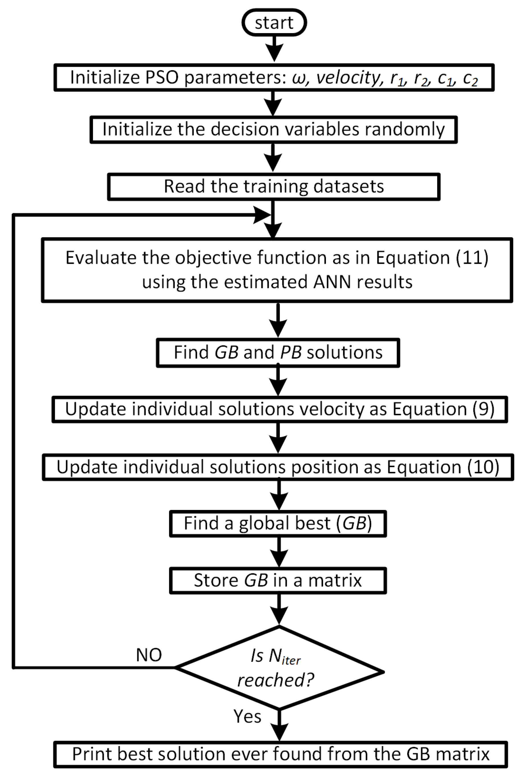
where X i denotes the decision variables included in the estimated data (y e ) and tested data y t , and n g denotes the total number of datasets. Thus, PSO is an important tool for determining the relevant decision variables as in Figure 5. The number of hidden layers and the number of neurons in each hidden layer constitute the decision variables in the current study.
The algorithm starts by reading the training data and initializes the decision variables randomly within the predetermined constrained. An iterative loop is set afterward, in which the ANN estimations are obtained and the objective function is then evaluated. In each iteration, the individual particles’ speed and position are updated according to Equations (9) and (10), respectively. The number of iterations is recorded, and the GB is then entered into a matrix to find the best solution ever obtained. The constraints are specified to keep the number of neurons and hidden layers to a maximum of ten. In addition to the RMSE, the following index is estimated as in Equation (12).
R E = R M S E y e ¯
where RMSE and RE are the relative and absolute errors, respectively. It’s worth noting that the lower the RMSE and RE, values are the better the developed ANN fits the provided datasets. Another important index is the correlation as in Equation (13), the variables marked with a bar denote the mean value of the associated parameters. On the other hand, as the value of R gets closer to the unity, it would imply the developed ANN regression behaves satisfactorily to best fit the given datasets.
R = i g ( y e y e ¯ ) i g ( y t y t ¯ ) i g ( y e y e ¯ ) 2 i g ( y t y t ¯ ) 2

Performance Indices 

In order to verify the robustness of the developed a near-optimal nn controller compared to the LLC and the ANFIS controllers, the robustness and effectiveness of the developed controllers are investigated by the following indices that are applied to the control effort (C f ) for 100 s as in Equations (14)–(17), in which t is the time. It is worth mentioning that the developed controllers’ time domain characteristics would be better when these indices are low [55].
I A E = 0 100 | C f 2 | d t
I T A E = 0 100 t | C f 2 | d t
I S E = 0 100 | C f | 2 d t
I T S E = 0 100 t | C f | 2 d t
where IAE is the integral absolute error, ITAE is the integral time-weighted absolute error, ISE is the integral square error and ITSE is the integral time-weighted square error.

4. Results and Discussion

In this section, the implementations of the developed controllers are investigated. Under different operational conditions, the developed ANN results are compared to both the ANFIS and LLC controllers. MATLAB/Simulink is used to elaborate the produced controllers. Afterward, we thoroughly discussed the simulation results of four different cases. Two-area power system with the SSSC under a three-phase fault is addressed in case 1, whereas case 2 presents the impact of the high-level penetration of the PV system on the two-area power system. Case 3 demonstrates the two-area power system performance with the three developed controllers under heavy load variation, taking into account the solar PV effect. Case 4 presents the impact of the 3-phase fault on the power system. In case 4, the effectiveness of the proposed controller is addressed under heavy loading conditions as well as the three-phase fault.

4.1. Implementation of the Neuro-Based Controllers

4.1.1. Implementation of the ANN Controller

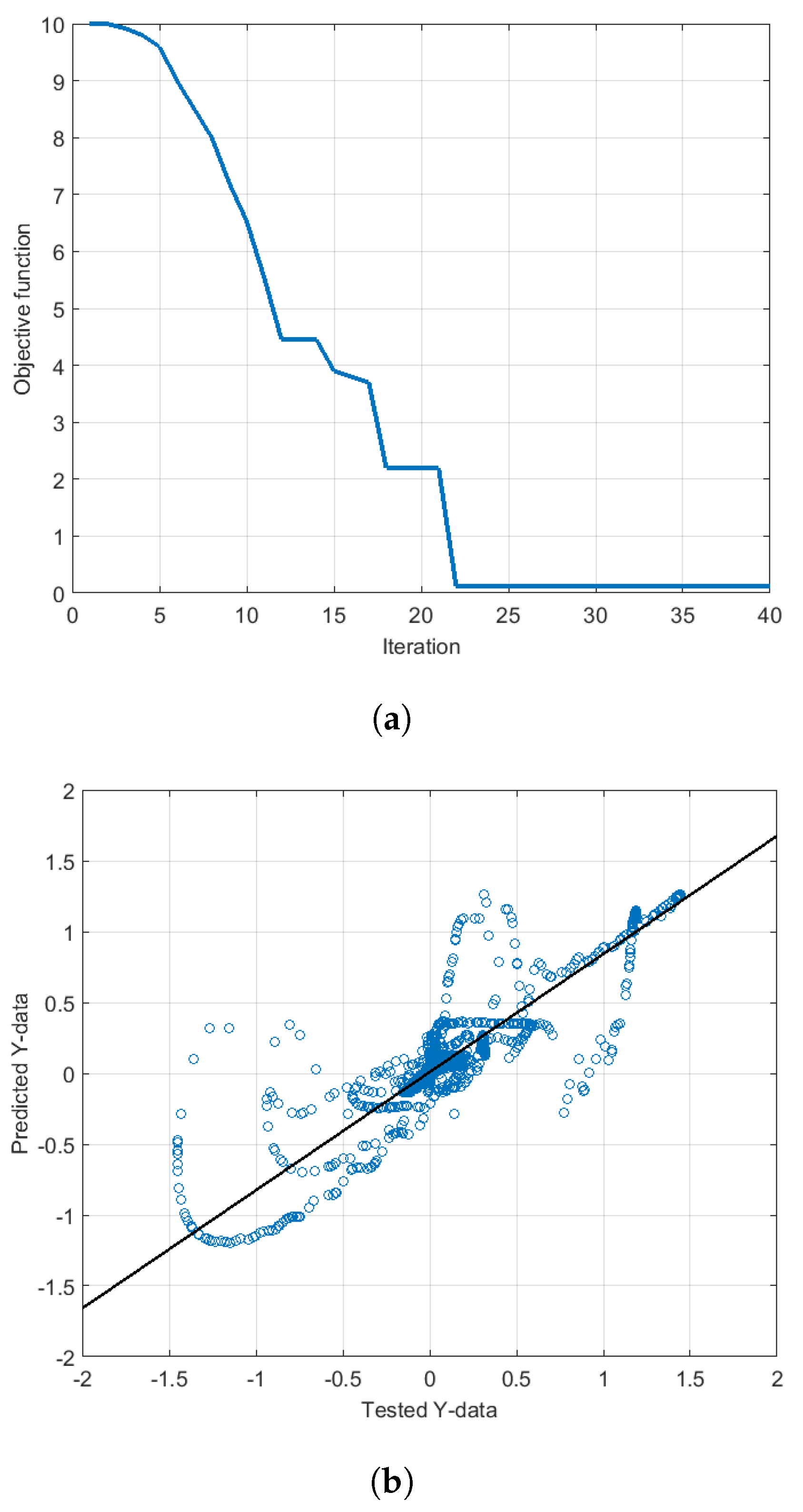
Over 100s, there would be 15,000 historical data sets, half of which are used for training and the remaining are used for testing. Such datasets’ dimensionality suggests either shallow or deep neural networks which will be investigated by the PSO. PSO was used to find the optimal number of the hidden layer and the number of neurons per layer. Primarily, a test number of the hidden layers (e.g., between 1 and 10 in this study) is assumed and the objective function in Equation (11) is minimized by the PSO. The PSO proceeds further to find the optimal number of neurons per layer. The cycle is repeated by the PSO by varying the test number of the hidden layers until a satisfactory solution is obtained. Each time the number of neurons and a number of hidden layers are recorded. The best solution is saved ever found during the number of iterations. The developed ANN’s configuration is shown in Figure 6. The developed ANN is made up of three hidden layers in addition to the output layer. Each hidden layer comprises several neurons with weights (W) and biases (b), and it is through these neurons that the output signals are supplied to a sigmoid function. The historical input and output data are obtained from the LLC counterpart under different faults and different levels of electrical demands. Such historical data are off-line given to the ANN as entering signals. The trained ANN is installed in the considered power system in order to validate the produced ANN-based controller. Since regression is the root of the developed ANN-based controllers, faults, PV penetration, load changes, and noises will be treated in an online manner through the regression nature. Figure 7a demonstrates the behavior of the objective function. In Figure 7b, the relationship between the predicted and the tested data is drawn, which demonstrates satisfactory performance. This is indicated by the straight-line approximation between the tested and predicted datasets. The features of the developed ANN are given in Table 1.

4.1.2. Implementation of the ANFIS Controller

In order to assess the predictive ability of the ANN-based regression controller, a comparison was made with the ANFIS findings. The ANFIS is a well-known generic predictive for academics, therefore it’s a good approach to be used. Half the datasets are used for training and the other half is utilized for testing the regression accuracy. ‘NeuroFuzzyDesigner’ in Matlab/Simulink library is employed to develop the ANFIS regressive-based controller [56], and based on this, the ANFIS features shown in Table 2 are obtained.
A comparison of the developed neuro-based controllers is demonstrated in Table 3. The results in Table 3 are achieved using three Sugeno-type membership functions. It is clear that the ANN controller shows satisfactory results in terms of the performance indices. The correlation R is closer to the unity, which implies better regression compared to the ANFIS. Besides, the RMSE and RE are smaller.

4.2. Case Studies

4.2.1. Case 1: Two-Area Power System with SSSC under Three-Phase Fault

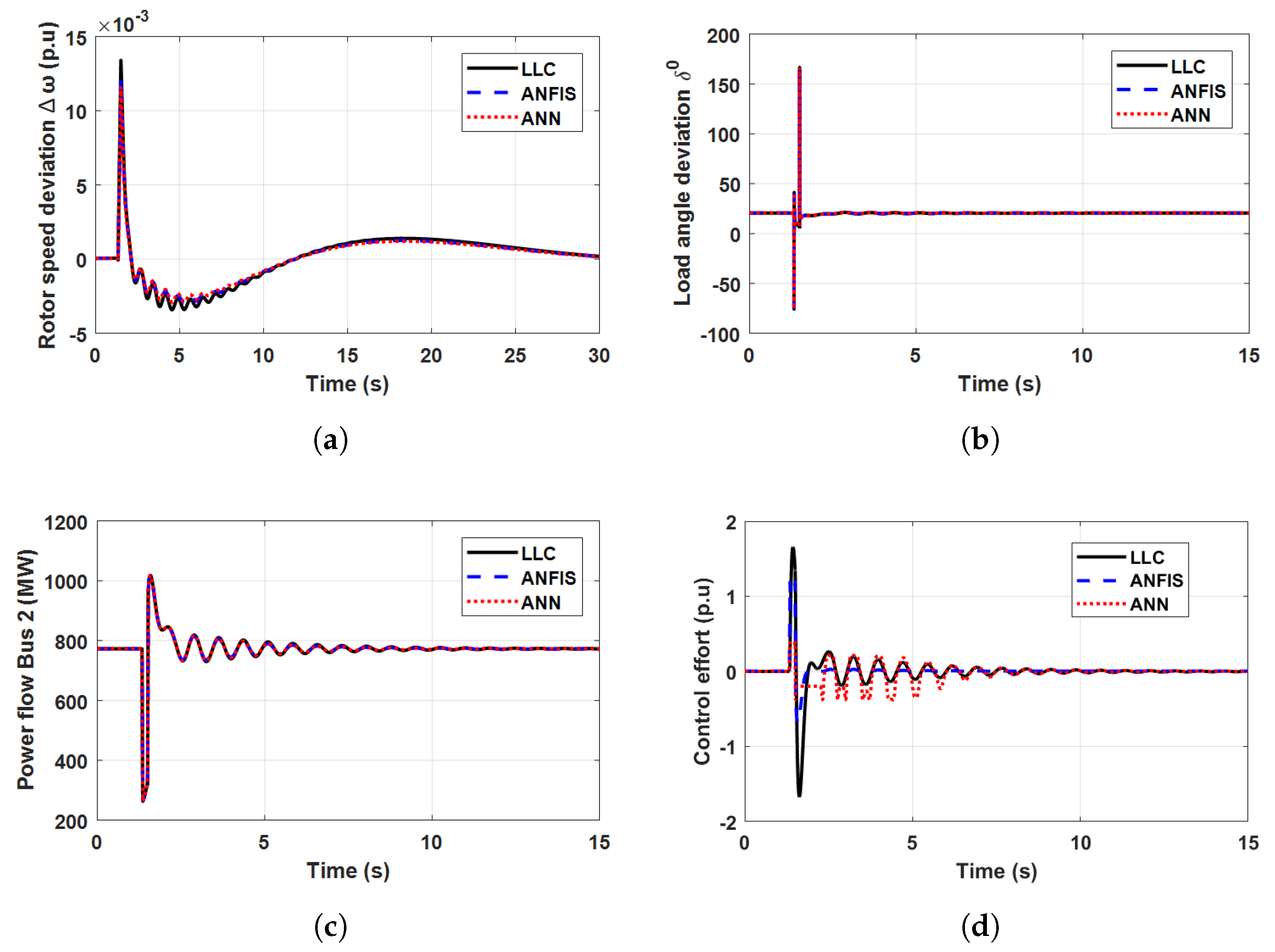
To investigate the effectiveness of the proposed controllers at nominal loading, which is tailored in the Appendix A and Appendix B, the solar PV is disconnected at bus 1. At t equals 1 s, a three-phase fault, which is self-cleared after ten cycles, takes place close by at bus 4 as in Figure 1. Figure 8 demonstrates the comparative results of the load angle and rotor speed deviations, the power flow through line 2, and the control effort. The developed neuro-based controllers perform admirably, suppressing system oscillations in a way that is comparable to that of the LLC controller. Nonetheless, all controllers restore system the stability adequately, and their usefulness is validated.

4.2.2. Case 2: Power System Performance with the Solar PV Injection

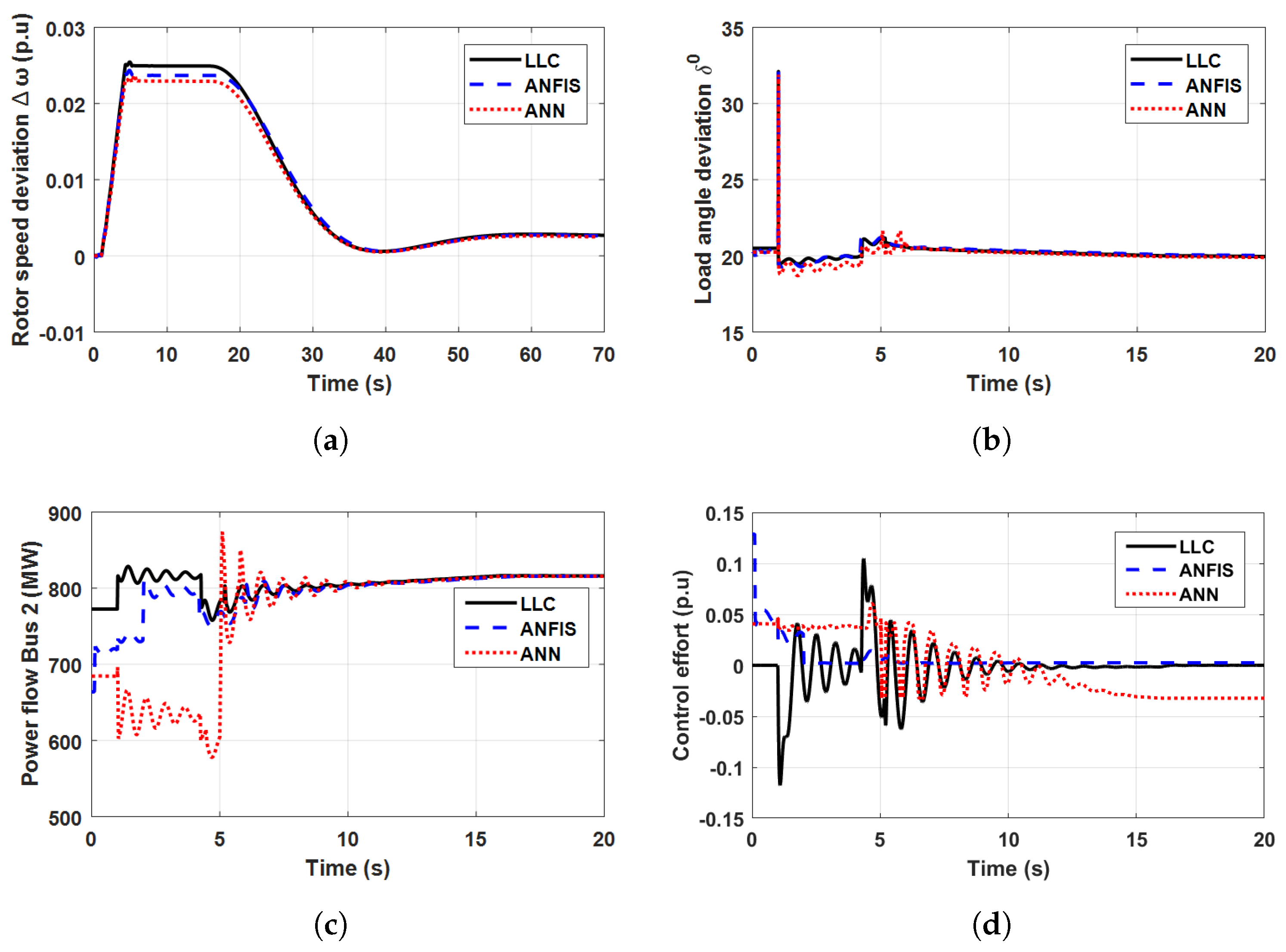
With the same loading conditions of the preceding case, at t equals 1s, the solar PV system is connected at bus 1. In this case, the fault conditions are not taken into account. The solar PV injection command (P r e f ) remains unchanged at 0.2 pu. In the section below, it is explained why this value was chosen. A comparison of the proposed ANN controller to the LLC and ANFIS with the SSSC power oscillation damping is demonstrated in Figure 9. The rotor speed deviation of the nearby area generator to the solar PV records an overshoot value of 0.025 pu compared to 0.027 pu for the LLC and yet it has outperformed the ANFIS controller by a little margin. Both the ANN and the ANFIS controllers still behave satisfactorily compared to the LLC controller to recover the steady-state stability of the system with small speed deviation overshoots and fewer oscillations. All controllers can deliver the energy flow through line 2 with satisfactory power angle and acceptable control effort behavior. The investigation of Figure 9 demonstrates the solar PV energy penetration considerably influences the rotor speed and the frequency deviations of the adjacent synchronous generator when compared to case 1 with the three-phase faults.

4.2.3. PV Penetrations Management

In this section, the impact of solar PV energy injection on conventional synchronous generator power plants is investigated. The influence of the PV penetration is demonstrated in Figure 10 under the assumption that the inverter can supply the PV power as quickly as per its time constant, which is quicker than the synchronous generator time constant. As expected, the results give rise to the essential impact of the solar PV upon the rotor speed deviations of the adjacent generator and so impact its area frequency. In Figure 10c, three P r e f , commands of the injected PV energy along with their corresponding real power are displayed. The PV energy management strategy disconnects the injected power in response to the frequency or terminal voltage limitations, which highlights the role of PV energy management. Because solar PV penetrations temporarily affect the electrical power supplied by conventional synchronous generators, the synchronous generator slows down for inconveniently long periods for PV injection commands greater than 0.5 pu. Accordingly, in the relevant investigated scenarios, 0.2 pu is chosen.

4.2.4. Case 3: Two-Area Power System under Heavy Loading

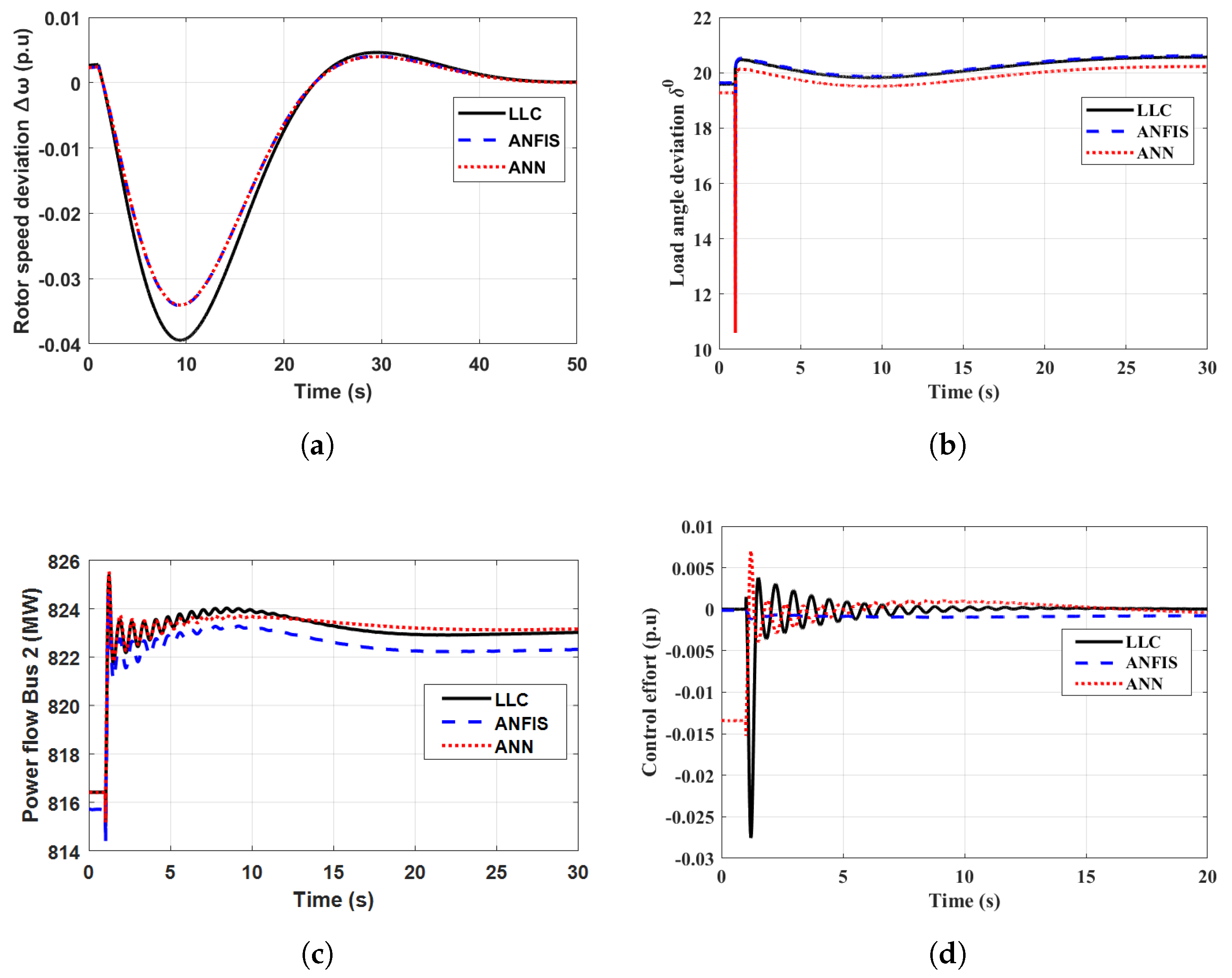
Under the same loading conditions of Section 4.2.1, at t equals 1s, a three-phase heavy load is connected at the middle of line 1 while the solar PV inverter provides energy to the system. The step load is 100MW, which represents 20% of the whole load demand. The fault conditions are not taken into account while evaluating the performance of the SSSC that is controlled by the developed controllers. Figure 11 shows the comparative results of the load angle and rotor speed deviations, the flow of power through line 2, and the corresponding control effort. The rotor speed deviation experiences the smallest undershoot for both the ANN and the ANFIS controller compared to the LLC controller. It is clear that the developed neuro-based controllers’ performance is satisfactory wherein the control effort is small and quickly able to dampen the oscillations.

4.2.5. Case 4: Impact of PV Injection with 3-Phase Fault

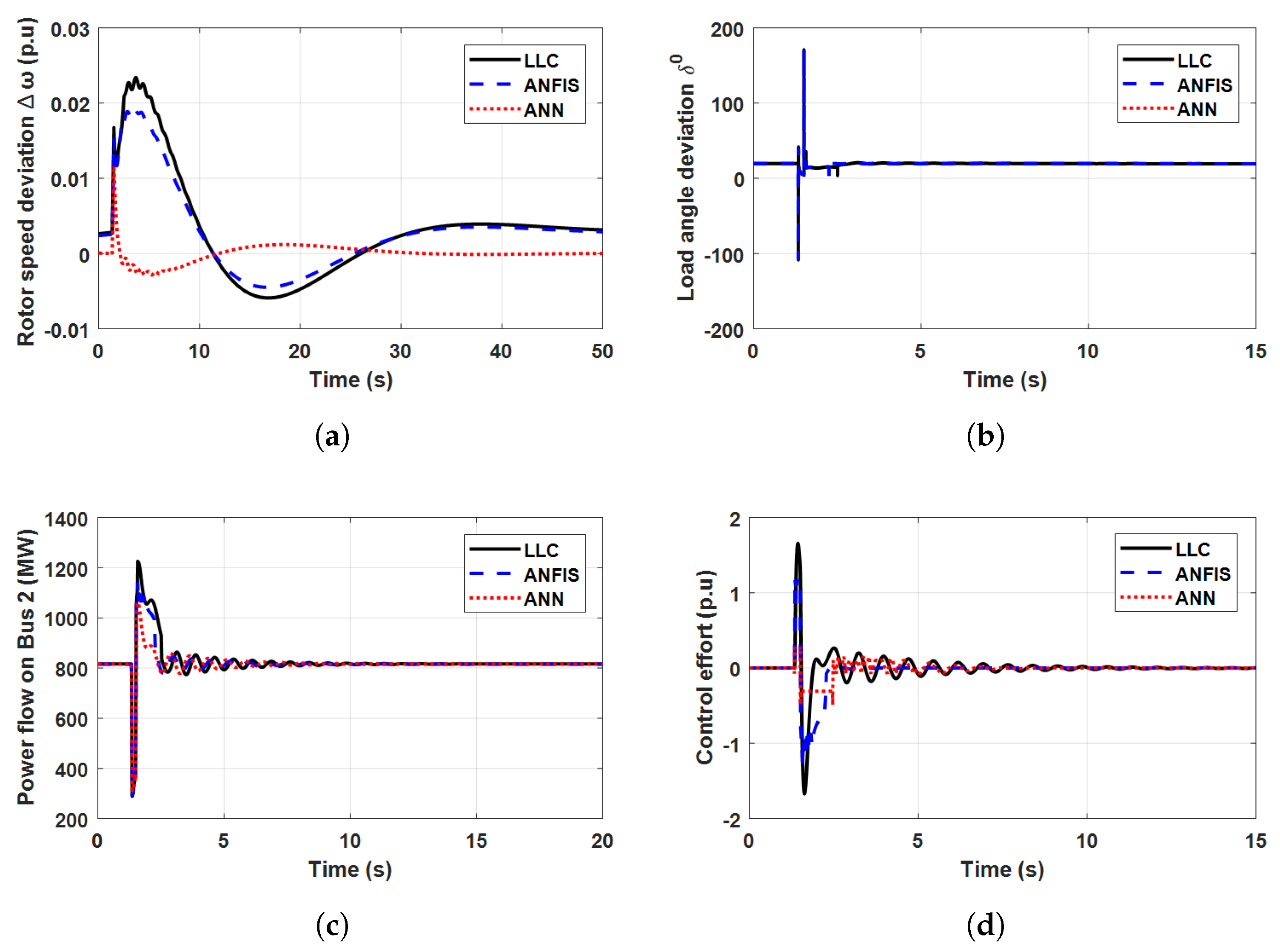
With the same loading conditions of Section 4.2.1, a three-phase fault occurs at transmission line 1. Meanwhile, the solar PV inverter delivers the electricity to the system at bus B1. As shown in Figure 12, the required time of the ANN controller to restore the system stability is remarkably less than those of ANFIS and LLC controllers. It is obvious that the ANN outperforms the other controllers. It demonstrates the smallest rotor speed overshoot of the solar PV nearby generator with zero steady-state error. Besides, the ANN controller performance is robust to suppress the oscillations with adequate control effort.

4.3. Two-Area Power System Performance Indices

The outputs in Figure 9c, Figure 11c and Figure 12c are dependent on the controller type. Different control efforts are made by each controller. The controller output, which is ultimately decoded as a PWM signal, represents the control effort and the line power flow typically changes as a result. A good controller will have reduced performance indices. Table 4 shows the different performance indices of the ANN, ANFIS, and LLC controllers as well as execution time. The biggest appeal is that the ANN controller records the shortest execution time. Besides, the ANN controller performance demonstrates the lowest system indices in most of the studies’ cases. It is clear that the developed ANN outperforms the other controllers and its robustness is affirmed.

5. Conclusions

In this study, the power damping oscillation of multi-machine hybrid microgrid systems is studied wherein two artificial intelligence neuro-based controllers are developed to suppress the low-frequency oscillations due to disruptive faults conditions. The SSSC is used to effectively dampen the adverse power frequency oscillations in two hydropower interconnected areas with considerable solar energy penetrations. The PSO is used to calculate the optimal architecture of artificial neural networks based on the ‘root mean square error’. Several performance indicators applied to the control effort signal are used to compare the effectiveness of the developed controllers. The generated optimum ANN controller is quantitatively evaluated and compared to the LLC and ANFIS controllers. Based on the simulation results and discussions, the following conclusions can be drawn: (1) when associated with appropriate controllers, SSSC provides efficient dampening of the adverse power frequency oscillations; (2) the artificial neural networks integrated with the SSSC technology, the developed PSO provides efficacy to minimize the “root mean square error” to optimally give structure to the number of hidden layers and the neurons in each layer; (3) the proposed artificial intelligence neuro-based controller serves as a supplemental control for the SSSC, providing a steady damping control signal; (4) in terms of system indices and execution time, it seems that the developed ANN controller outperforms the traditional LLC and ANFIS controllers. Furthermore, it performs well in restoring system stability, particularly in areas where solar energy penetration is considerable. Consequently, the current study recommends utilizing artificial neural networks for future hybrid microgrid applications after the unexpected barriers and disruptive faults to effectively collect big data and transform it into illuminating learning that increases stability.
For the purpose of future works, more renewable energy resources, as well as synchronous generators, might be added to hybrid microgrid systems to comprehensively study power-damping oscillations under more heavy data and communications restrictions.

Author Contributions

Conceptualization, M.A., A.Y.A. and F.K.A.-E.; Data curation, M.A. and F.K.A.-E.; Formal analysis, M.A. and F.K.A.-E.; Investigation, M.A. and F.K.A.-E.; Methodology, M.A.; Project administration, M.A. and J.H.; Resources, M.A., A.Y.A. and F.K.A.-E.; Software, M.A. and F.K.A.-E.; Supervision, A.Y.A. and Z.W.G.; Validation, M.A. and F.K.A.-E.; Visualization, M.A. and F.K.A.-E.; Writing—original draft, M.A., A.Y.A. and F.K.A.-E.; Writing, review, and editing, M.A., A.Y.A., Z.W.G., J.H. and F.K.A.-E. All authors have read and agreed to the published version of the manuscript.

Funding

This research was supported by the Energy Cloud R&D Program through the National Research Foundation of Korea (NRF) funded by the Ministry of Science, ICT (2019M3F2A1073164).

Conflicts of Interest

The authors declare no conflict of interest.

Appendix A. Parameters of the Particle Swarm Optimizer

‘PSO’ parameters are: population = 20,  ω  = 0.1, c 1  = 0.25, c 2  = 0.99, r 1  = 0.3, r 2  = 0.45, number of iterations = 40.

Appendix B. Distributed Network

The two-area power system parameters together with the solar PV energy penetration are demonstrated in Table A1.
Table A1. Parameters of the two-area power system.
QuantitySymbolValue
GeneratorsRatingP 1  = 2100 MW, P 1  = 1400 MW
Terminal voltage13.8 kV
[X d  X d  X d  X q  X q  X 1 ][1.305 0.296 0.252 0.474 0.243 0.18] pu
[T d  T d  T q o ][1.01 0.053 0.1] pu
armature resistance2.8544 m Ω
inertia constant (H)3.7 sW/VA
Number of poles32
Friction coefficient0.0
PVRating2100 MW
Terminal voltage (rms)13.8 kV
TransformerRating2100 MW
[V 1  R 1  L 1 ][13.8 kV 0.002  Ω  0.0  Ω ]
[V 2  R 2  L 2 ][500 kV 0.002  Ω  0.02  Ω ]
[R m  X m ][500  Ω  500  Ω ]
frequencyf60 Hz
Loadsat bus 1250 MW
at bus 250 MW
at bus 2220 MW + 100 MVAr
at mid-Line 1100 MW
SSSCRating100 MVA
V n o m i n a l 500 kV
V D C 40 kV
C D C 375  μ F
R0.00533  Ω
L0.16 H
Transmission LinesLine 1150 km + 150 km
Line 2280 km
Resistance0.00021 pu/km
Reactance0.003 pu/km
B C 0.00175 pu/km

References

  1. Kumar, R.; Diwania, S.; Khetrapal, P.; Singh, S.; Badoni, M. Multimachine stability enhancement with hybrid PSO-BFOA based PV-STATCOM. Sustain. Comput. Inform. Syst. 2021, 32, 100615. [Google Scholar] [CrossRef]
  2. Rachananjali, K.; Naik, S.; Bala, K.K.; Srinivasa, R.Y. Efficient modeling and simulation of grid connected MMC for sustainable photovoltaic and wind conversion system. Sustain. Comput. Inform. Syst. 2020, 28, 100402. [Google Scholar]
  3. Banaei, M.; Toloue, H.; Kazemi, F.M.; Oskuee, M.R.J. Damping of power system oscillations using imperialist competition algorithm in power system equipped by HVDC. Ain Shams Eng. J. 2015, 6, 75–84. [Google Scholar] [CrossRef] [Green Version]
  4. Moradi, M.H.; Amiri, F. Virtual inertia control in islanded microgrid by using robust model predictive control (RMPC) with considering the time delay. Soft Comput. 2021, 25, 6653–6663. [Google Scholar] [CrossRef]
  5. Saadatmand, M.; Gharehpetian, G.B.; Kamwa, I.; Siano, P.; Guerrero, J.M.; Haes Alhelou, H. A Survey on FOPID controllers for LFO damping in Power systems using synchronous generators, FACTS devices and inverter-based power plants. Energies 2021, 14, 5983. [Google Scholar] [CrossRef]
  6. Ortega, R.; García, V.H.; García-García, A.L.; Rodriguez, J.J.; Vásquez, V.; Sosa-Savedra, J.C. Modeling and Application of Controllers for a Photovoltaic Inverter for Operation in a Microgrid. Sustainability 2021, 13, 5115. [Google Scholar] [CrossRef]
  7. Pathan, M.I.H.; Rana, M.J.; Shahriar, M.S.; Shafiullah, M.; Zahir, M.H.; Ali, A. Real-time LFO damping enhancement in electric networks employing PSO optimized ANFIS. Inventions 2020, 5, 61. [Google Scholar] [CrossRef]
  8. Patsalides, M.; Papadimitriou, C.N.; Efthymiou, V. Low Inertia Systems Frequency Variation Reduction with Fine-Tuned Smart Energy Controllers. Sustainability 2021, 13, 2979. [Google Scholar] [CrossRef]
  9. Nikolaev, N.; Dimitrov, K.; Rangelov, Y. A Comprehensive Review of Small-Signal Stability and Power Oscillation Damping through Photovoltaic Inverters. Energies 2021, 14, 7372. [Google Scholar] [CrossRef]
  10. Gheisarnejad, M.; Khooban, M.H. Secondary load frequency control for multi-microgrids: HiL real-time simulation. Soft Comput. 2019, 23, 5785–5798. [Google Scholar] [CrossRef]
  11. Saleem, B.; Badar, R.; Judge, M.A.; Manzoor, A.; ul Islam, S.; Rodrigues, J.J. Adaptive recurrent NeuroFuzzy control for power system stability in smart cities. Sustain. Energy Technol. Assess. 2021, 45, 101089. [Google Scholar] [CrossRef]
  12. Mahendran, K.; Prabha, S. Optimal control strategies for a hybrid renewable energy system: An ALANN/RNN technique. Soft Comput. 2019, 23, 13459–13475. [Google Scholar] [CrossRef]
  13. Yousef, A.M.; Abo-Elyousr, F.K.; Elnozohy, A.; Mohamed, M.; Abdelwahab, S.A.M. Fractional Order PI Control in Hybrid Renewable Power Generation System to Three Phase Grid Connection. Int. J. Electr. Eng. Inform. 2020, 12, 470–493. [Google Scholar] [CrossRef]
  14. Abo-Elyousr, F.K.; Abbas, H.S.; Yousef, A.M.; Quynh, N.V.; Ali, Z.M.; Nazir, M.S. Oscillation Damping for Wind Energy Conversion System with Doubly Fed Induction Generator Association with Synchronous Generator. Energies 2020, 13, 5067. [Google Scholar] [CrossRef]
  15. Çelik, E. Design of new fractional order PI–fractional order PD cascade controller through dragonfly search algorithm for advanced load frequency control of power systems. Soft Comput. 2021, 25, 1193–1217. [Google Scholar] [CrossRef]
  16. Sahoo, S.; Jena, N.K.; Ray, P.K.; Sahu, B.K. Selfish Herd Optimisation tuned fractional order cascaded controllers for AGC Analysis. Soft Comput. 2021, 26, 2835–2853. [Google Scholar] [CrossRef]
  17. Abo-Elyousr, F.K.; Abdelaziz, A.Y. A Novel modified robust load frequency control for mass-less inertia photovoltaics penetrations via hybrid PSO-WOA approach. Electr. Power Components Syst. 2019, 47, 1744–1758. [Google Scholar] [CrossRef]
  18. Lei, B.; Fei, S. A brand new nonlinear robust control design of SSSC for transient stability and damping improvement of multi-machine power systems via pseudo-generalized Hamiltonian theory. Control. Eng. Pract. 2014, 29, 147–157. [Google Scholar] [CrossRef]
  19. Sonfack, L.L.; Kenné, G.; Fombu, A.M. An improved adaptive RBF neuro-sliding mode control strategy: Application to a static synchronous series compensator controlled system. Int. Trans. Electr. Energy Syst. 2019, 29, e2835. [Google Scholar] [CrossRef]
  20. Maleki, H.; Varma, R.K. Coordinated control of PV solar system as STATCOM (PV-STATCOM) and Power System Stabilizers for power oscillation damping. In Proceedings of the 2016 IEEE Power and Energy Society General Meeting (PESGM), Boston, MA, USA, 17–21 July 2016; pp. 1–5. [Google Scholar]
  21. Cabrera-Tobar, A.; Bullich-Massagué, E.; Aragüés-Pe nalba, M.; Gomis-Bellmunt, O. Active and reactive power control of a PV generator for grid code compliance. Energies 2019, 12, 3872. [Google Scholar] [CrossRef] [Green Version]
  22. Ambafi, J.G.; Adamu, S.S. Optimal siting, sizing, and parameter tuning of STATCOM and SSSC using MPSO and remote coordination of the FACTS for oscillation damping of power systems. Turk. J. Electr. Eng. Comput. Sci. 2019, 27, 4580–4595. [Google Scholar] [CrossRef]
  23. Panda, S.; Padhy, N.; Patel, R. Power-system stability improvement by PSO optimized SSSC-based damping controller. Electr. Power Components Syst. 2008, 36, 468–490. [Google Scholar] [CrossRef]
  24. Ghatak, A.; Pandit, T.; Ramanathan, V. Comparative Analysis of Control Systems of Distribution Static Synchronous Compensator. In Proceedings of the 2021 2nd International Conference on Smart Electronics and Communication (ICOSEC), Trichy, India, 7–9 October 2021; pp. 512–517. [Google Scholar]
  25. Kar, M.K.; Kumar, S.; Singh, A.K.; Panigrahi, S. A modified sine cosine algorithm with ensemble search agent updating schemes for small signal stability analysis. Int. Trans. Electr. Energy Syst. 2021, 31, e13058. [Google Scholar] [CrossRef]
  26. Hemeida, M.; Rezk, H.; Hamada, M.M. A comprehensive comparison of STATCOM versus SVC-based fuzzy controller for stability improvement of wind farm connected to multi-machine power system. Electr. Eng. 2018, 100, 935–951. [Google Scholar] [CrossRef]
  27. Roy, R.; Mukherjee, V.; Singh, R.P. Harris hawks optimization algorithm for model order reduction of interconnected wind turbines. ISA Trans. 2021, 128, 372–385. [Google Scholar] [CrossRef]
  28. Sakipour, R.; Abdi, H. Voltage stability improvement of wind farms by self-correcting static volt-ampere reactive compensator and energy storage. Int. J. Electr. Power Energy Syst. 2022, 140, 108082. [Google Scholar] [CrossRef]
  29. Abdelsattar, M.; Arafa Hafez, W.; A. Elbaset, A.; Kamel, S.; H. Kasem Alaboudy, A.; Khan, B.; A. Zaki Diab, A. Voltage stability improvement of an Egyptian power grid-based wind energy system using STATCOM. Wind Energy 2022, 25, 1077–1120. [Google Scholar] [CrossRef]
  30. Tavakoli, A.R.; Seifi, A.R.; Arefi, M.M. Fuzzy-PSS and fuzzy neural network non-linear PI controller-based SSSC for damping inter-area oscillations. Trans. Inst. Meas. Control. 2018, 40, 733–745. [Google Scholar] [CrossRef]
  31. Tavakoli, A.R.; Seifi, A.R.; Arefi, M.M. Designing a self-constructing fuzzy neural network controller for damping power system oscillations. Fuzzy Sets Syst. 2019, 356, 63–76. [Google Scholar] [CrossRef]
  32. Shi, Z.; Yao, W.; Li, Z.; Zeng, L.; Zhao, Y.; Zhang, R.; Tang, Y.; Wen, J. Artificial intelligence techniques for stability analysis and control in smart grids: Methodologies, applications, challenges and future directions. Appl. Energy 2020, 278, 115733. [Google Scholar] [CrossRef]
  33. Badar, R.; Dilshad, S. Type-II neuro fuzzy wavelet control for power system stability enhancement using STATCOM. In Proceedings of the 2016 19th International Multi-Topic Conference (INMIC), Islamabad, Pakistan, 5–6 December 2016; pp. 1–7. [Google Scholar]
  34. Abas, N.; Dilshad, S.; Khalid, A.; Saleem, M.S.; Khan, N. Power quality improvement using dynamic voltage restorer. IEEE Access 2020, 8, 164325–164339. [Google Scholar] [CrossRef]
  35. Jolfaei, M.G.; Sharaf, A.M.; Shariatmadar, S.M.; Poudeh, M.B. A hybrid PSS–SSSC GA-stabilization scheme for damping power system small signal oscillations. Int. J. Electr. Power Energy Syst. 2016, 75, 337–344. [Google Scholar] [CrossRef]
  36. Sahu, P.R.; Hota, P.K.; Panda, S. Modified whale optimization algorithm for coordinated design of fuzzy lead-lag structure-based SSSC controller and power system stabilizer. Int. Trans. Electr. Energy Syst. 2019, 29, e2797. [Google Scholar] [CrossRef]
  37. Gurung, S.; Naetiladdanon, S.; Sangswang, A. Coordination of power-system stabilizers and battery energy-storage system controllers to improve probabilistic small-signal stability considering integration of renewable-energy resources. Appl. Sci. 2019, 9, 1109. [Google Scholar] [CrossRef] [Green Version]
  38. Ibrahim, Y.; Kamel, S.; Rashad, A.; Nasrat, L.; Jurado, F. Performance Enhancement of Wind Farms Using Tuned SSSC Based on Artificial Neural Network. Int. J. Interact. Multim. Artif. Intell. 2019, 5, 118–124. [Google Scholar] [CrossRef] [Green Version]
  39. Badar, R.; Khan, L. Power system oscillations damping using HABsW based FACTS-SSSC. J. Intell. Fuzzy Syst. 2014, 27, 1575–1587. [Google Scholar] [CrossRef]
  40. Badar, R.; Khan, M.Z.; Javed, M.A. MIMO adaptive bspline-based wavelet neurofuzzy control for multi-type facts. IEEE Access 2020, 8, 28109–28122. [Google Scholar] [CrossRef]
  41. Gholipour, E.; Nosratabadi, S.M. A new coordination strategy of SSSC and PSS controllers in power system using SOA algorithm based on Pareto method. Int. J. Electr. Power Energy Syst. 2015, 67, 462–471. [Google Scholar] [CrossRef]
  42. Nahak, N.; Satapathy, O. Investigation and damping of electromechanical oscillations for grid integrated micro grid by a novel coordinated governor-fractional power system stabilizer. Energy Sources Part A Recover. Util. Environ. Eff. 2021, 1–29. [Google Scholar] [CrossRef]
  43. Waseem, M.; Lin, Z.; Liu, S.; Zhang, Z.; Aziz, T.; Khan, D. Fuzzy compromised solution-based novel home appliances scheduling and demand response with optimal dispatch of distributed energy resources. Appl. Energy 2021, 290, 116761. [Google Scholar] [CrossRef]
  44. Waseem, M.; Lin, Z.; Liu, S.; Sajjad, I.A.; Aziz, T. Optimal GWCSO-based home appliances scheduling for demand response considering end-users comfort. Electr. Power Syst. Res. 2020, 187, 106477. [Google Scholar] [CrossRef]
  45. Balouch, S.; Abrar, M.; Abdul Muqeet, H.; Shahzad, M.; Jamil, H.; Hamdi, M.; Malik, A.; Hamam, H. Optimal Scheduling of Demand Side Load Management of Smart Grid Considering Energy Efficiency. Front. Energy Res. 2022, 10, 861571. [Google Scholar]
  46. Elnozahy, A.; Abd-Elbary, H.; Abo-Elyousr, F.K. Efficient energy harvesting from PV Panel with reinforced hydrophilic nano-materials for eco-buildings. Energy Built Environ. 2022, in press. [Google Scholar] [CrossRef]
  47. Ramadan, H.S.; Helmi, A.M.; Abo-Elyousr, F.K. Optimal resilient facade thermal photovoltaic clustering allocation for microgrid enhanced voltage profile. Int. J. Electr. Power Energy Syst. 2023, 148, 108940. [Google Scholar] [CrossRef]
  48. SSSC (Phasor Model). Available online: https://www.mathworks.com/help/physmod/sps/ug/sssc-phasor-model.html/ (accessed on 13 March 2022).
  49. Abo-Elyousr, F.K.; Nassrat, L. Evaluation of flashover voltage levels of contaminated hydrophobic polymer insulators using regression trees, neural networks, and adaptive neuro-fuzzy. Telkomnika 2018, 16, 495–512. [Google Scholar] [CrossRef]
  50. Renjini, G.; Devi, V. Artificial neural network controller based cleaner battery-less fuel cell vehicle with EF2 resonant DC-DC converter. Sustain. Comput. Inform. Syst. 2022, 35, 100667. [Google Scholar]
  51. Ramezani, F.; Nikoo, M.; Nikoo, M. Artificial neural network weights optimization based on social-based algorithm to realize sediment over the river. Soft Comput. 2015, 19, 375–387. [Google Scholar] [CrossRef]
  52. Chatterjee, S.; Das, A. A novel systematic approach to diagnose brain tumor using integrated type-II fuzzy logic and ANFIS (adaptive neuro-fuzzy inference system) model. Soft Comput. 2020, 24, 11731–11754. [Google Scholar] [CrossRef]
  53. Suparta, W.; Putro, W.S. Comparison of tropical thunderstorm estimation between multiple linear regression, Dvorak, and ANFIS. Bull. Electr. Eng. Inform. 2017, 6, 149–158. [Google Scholar] [CrossRef]
  54. Fetzer, D. Development of a MATLAB/Simulink Framework for Phasor-Based Power System Simulation and Component Modeling Based on State Machines; Kassel University Press GmbH: Kassel, Germany, 2018; Volume 7. [Google Scholar]
  55. Abo-Elyousr, F.K.; Sharaf, A.M. A novel modified robust load frequency controller scheme. Energy Syst. 2020, 11, 1175–1198. [Google Scholar] [CrossRef]
  56. Train Adaptive Neuro-Fuzzy Inference Systems. Available online: https://www.mathworks.com/help/fuzzy/train-adaptive-neuro-fuzzy-inference-systems-gui.html (accessed on 13 March 2022).
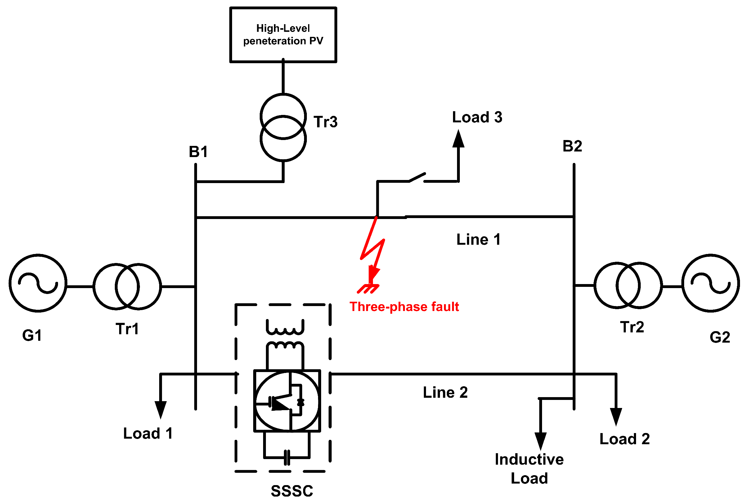
Figure 1. Investigated hybrid microgrid System.
Energies 16 02391 g001
Figure 2. Controller design for the SSSC.
Energies 16 02391 g002
Figure 3. Basic ANN construction. (a) Basic neuron construction [49]; (b) ANN design.
Energies 16 02391 g003
Figure 4. Phasor model of the on-grid solar PV.
Energies 16 02391 g004
Figure 5. Optimal ANN design for the SSSC controller.
Energies 16 02391 g005
Figure 6. Developed ANN model.
Energies 16 02391 g006
Figure 7. Basic ANN Performance. (a) RMSE against number of iteration. (b) Regression performance.
Energies 16 02391 g007
Figure 8. Case 1: Two-area power System with SSSC. (a) Rotor speed deviation. (b) Load angle deviation. (c) Flow of power through the line 2. (d) control effort.
Energies 16 02391 g008
Figure 9. Case 2: Two-area power System with microgrid based on PV. (a) Rotor speed deviation. (b) Load angle deviation. (c) Flow of power through the line 2. (d) control effort.
Energies 16 02391 g009
Figure 10. Influence of the PV penetrations. (a) Rotor speed deviation. (b) Load angle deviation. (c) Injected PV power at bus B1. (d) control effort.
Energies 16 02391 g010
Figure 11. Case 3: Two-area power system under heavy load variation. (a) Rotor speed deviation. (b) Load angle deviation. (c) Flow of power through the line 2. (d) control effort.
Energies 16 02391 g011
Figure 12. Case 4: Impact 3-phase fault upon the two-area power system. (a) Rotor speed deviation. (b) Load angle deviation. (c) Flow of power through the line 2. (d) control effort.
Energies 16 02391 g012
Table 1. ANN architecture information.
ParameterValue
number of layers4
number of hidden layers3
number of neurons per layer(10,7,4,1)
number of inputs1
number of outputs1
number of weightings134
Training functionLevenberg–Marquardt backpropagation
Table 2. ANFIS architecture features.
ParameterValue
Number of nodes16
Number of linear parameters6
Number of nonlinear parameters9
Number of training data pairs75,236
Number of fuzzy rules3
Membership function typegbellmf
Number of epoches40
Table 3. Regression architecture features.
ParameterANNANFIS
RMSE0.1190.143
RE2.1962.723
R0.9170.879
Table 4. Oscillation damping performance indices.
CaseControllerIAEISEITAEITSEExecution Time (s)
Case 1, three phase faultLLC1.270.638532.531.28 2.2480 × 10 3
ANFIS0.7070.23273611.88 2.0261 × 10 3
ANN1.40.2131.410.72 1.1160 × 10 3
Case 2, impact of PVLLC0.5260.04413.10.56 3.0113 × 10 3
ANFIS0.330.00512.370.0018 2.7140 × 10 3
ANN0.230.00128.4850.0016 1.4949 × 10 3
Case 3, impact of load variationLLC0.33320.0491.60.044   3.2313 × 10 3
ANFIS0.063380.00310.660.019 2.9123 × 10 3
ANN0.00980.001030.540.014 1.595 × 10 3
Case 4, impact of PV with severe faultLLC1.4760.975861.848 4.0281 × 10 3
ANFIS1.250.682452.4435.14 3.6304 × 10 3
ANN1.20.285551.410.72 1.9884 × 10 3
Disclaimer/Publisher’s Note: The statements, opinions and data contained in all publications are solely those of the individual author(s) and contributor(s) and not of MDPI and/or the editor(s). MDPI and/or the editor(s) disclaim responsibility for any injury to people or property resulting from any ideas, methods, instructions or products referred to in the content.