Article

Analysis of the Combustion Process in a Hydrogen-Fueled CFR Engine

by
Stefano Beccari
*,
Emiliano Pipitone
and
Salvatore Caltabellotta
Department of Engineering, University of Palermo, 90128 Palermo, Italy
*
Author to whom correspondence should be addressed.
Energies 2023, 16(5), 2351; https://doi.org/10.3390/en16052351
Submission received: 4 February 2023 / Revised: 21 February 2023 / Accepted: 26 February 2023 / Published: 1 March 2023
(This article belongs to the Special Issue Experiments and Simulations of Combustion Process)

Abstract

:
Green hydrogen, produced using renewable energy, is nowadays one of the most promising alternatives to fossil fuels for reducing pollutant emissions and in turn global warming. In particular, the use of hydrogen as fuel for internal combustion engines has been widely analyzed over the past few years. In this paper, the authors show the results of some experimental tests performed on a hydrogen-fueled CFR (Cooperative Fuel Research) engine, with particular reference to the combustion. Both the air/fuel (A/F) ratio and the engine compression ratio (CR) were varied in order to evaluate the influence of the two parameters on the combustion process. The combustion duration was divided in two parts: the flame front development (characterized by laminar flame speed) and the rapid combustion phase (characterized by turbulent flame speed). The results of the hydrogen-fueled engine have been compared with results obtained with gasoline in a reference operating condition. The increase in engine CR reduces the combustion duration whereas the opposite effect is observed with an increase in the A/F ratio. It is interesting to observe how the two parameters, CR and A/F ratio, have a different influence on the laminar and turbulent combustion phases. The influence of both A/F ratio and engine CR on heat transfer to the combustion chamber wall was also evaluated and compared with the gasoline operation. The heat transfer resulting from hydrogen combustion was found to be higher than the heat transfer resulting from gasoline combustion, and this is probably due to the different quenching distance of the two fuels.

1. Introduction

Over the last decades, changes in climate have dramatically drawn the attention of the scientific community, which has pledged to find a solution. The release of anthropogenic greenhouse gas emissions is the most important issue to address in order to reduce global warming. To this purpose, the only mid-long-term solution is to replace fossil fuels with renewable energy sources. To mitigate the intrinsic randomness and periodicity of solar and wind energies, an effective storage system is needed. A feasible solution is the electric energy storage by using batteries which, however, has some disadvantages: the great amount of energy needed for both manufacturing and end-of-life disposal, and the rarity of raw materials. Both Shu et al. [1] and Picatoste et al. [2] explored the lifecycle and environmental impact of the batteries used in electric passenger cars. A second feasible solution to store renewable energy is to produce hydrogen by electrolysis from water. Mazzeo et al. [3] discussed green hydrogen production by using photovoltaic and wind-renewable systems; Lee et al. [4] explored green hydrogen production via a hybrid system of alkaline water electrolysis and an energy storage system based on seasonal solar radiation. The combustion of hydrogen, under proper conditions, produces only water and thus it is the best candidate to substitute traditional fossil fuels. In particular, over the last few years, the use of hydrogen as a fuel in internal combustion engines (ICE) has been widely analyzed both in traditional vehicles and in Hybrid Electric Vehicles (HEV). White et al. [5] conducted a technical review on hydrogen-fueled ICE whereas Verhelst et al. [6,7] described the recent progress in the same topic. Saafi et al. [8] explored the potential of hydrogen in decarbonizing China’s light-duty vehicle market. Sopena et al. [9] compared the performance of a commercial spark ignition (SI) engine when fueled with gasoline and hydrogen. Keller et al. [10] explored the use of hydrogen in HEV and Wang et al. [11] conducted a state-of-the-art review on the same topic. Arat [12,13] tested an HEV engine with hydrogen-enriched traditional fuels. He et al. [14] and Nakajima et al. [15] performed a theoretical and experimental activity on an hydrogen-fueled HEV.
Green hydrogen has some unquestionable advantages over the traditional fossil fuels when used in ICE. First, owing to its high laminar flame speed, as reported by Dahoe [16], it produces a shorter combustion duration if compared with hydrocarbon fuels (gasoline or methane, for example) and this increases the engine thermodynamic efficiency. Despite having a lower standard density than conventional hydrocarbons, hydrogen’s volumetric power density is comparable to that of other gaseous fuels such as methane or propane due to its lower heating value per unit mass, which is almost three times higher than conventional hydrocarbons. Table 1 resumes some properties of hydrogen and hydrogen–air stoichiometric mixture and compares them with methane and isooctane.
There are also some issues related to the use of hydrogen as fuel for internal combustion engines: its high reactivity (low activation energy and high flame speed) often produces, for near stoichiometric mixtures, pre-ignition or auto-ignition phenomena, and in turn, knocking; and the high flame temperature and short quenching distance (Table 1) produce high heat transfer to the combustion chamber wall [17] and reduce engine efficiency. Moreover, the high combustion temperature produces high NOx emissions (the only pollutant emitted by hydrogen-fueled engines). All these issues may find a solution by using very lean mixtures, whose stable combustion is allowed by the very large flammability limits of hydrogen (Table 1). The very lean mixture lowers flame temperature and fuel reactivity, so it greatly reduces NOx emissions, heat transfer and knock occurrence. As a consequence, high engine volumetric compression ratios can be implemented with subsequent high engine efficiency. On the other hand, the use of a lean hydrogen–air mixture results in a reduced power density of internal combustion engines due to the mixture’s low volumetric energy. However, this issue can be effectively addressed by implementing supercharging or turbocharging. Both Nagalingam et al. [18] and Berckmüller et al. [19] explored the performance and potential of supercharged hydrogen-fueled SI engines; Natkin et al. [20] studied the performance and NOx emissions of a boosted hydrogen IC engine. Combustion is the most critical process in an ICE as its development greatly influences the engine performance and efficiency. The ideal combustion in a spark ignition (SI) engine should be instantaneous, which means at a constant volume and adiabatic in order to fully convert thermal energy into mechanical work. The study of hydrogen combustion, with particular reference to the flame front speed and the heat transfer to the cylinder wall, is fundamental to predict the hydrogen engine behavior and to fully exploit the benefits of this fuel. Salvi et al. [21] studied the influence of a hydrogen-fueled SI engine compression ratio (CR), spark advance (SA), exhaust gas recirculation (EGR) and A/F ratio on combustion duration. The authors analyzed two distinct phases of the combustion process, which are commonly known as the development phase and the rapid combustion phase. The development phase is characterized by a laminar flame speed and is conventionally defined as the period between the spark timing and the crank angle (CA) corresponding to 5% of mass fraction burned (MFB). On the other hand, the rapid combustion phase is characterized by a turbulent flame speed and is conventionally defined as the period between the two CAs corresponding to 5% and 90% of MFB. The engine CR was varied between 4.5 and 7.2, the equivalence ratio (stoichiometric A/F ratio divided by actual A/F ratio) was varied between 0.5 and 0.8 and the EGR was varied up to 25% by volume. It was found that both CR and equivalence ratio increments produce a decrease of combustion duration (both laminar and turbulent component); with a CR of 7.2, the equivalence ratio must be limited to 0.8 to avoid knocking and an EGR of 23.5% by volume allowed a knock-safe operation with an equivalence ratio of 0.9; however, this increased the combustion duration. Shudo et al. [17], using a SI engine with fixed CR, explored the effects of the hydrogen A/F ratio on heat exchanges with the chamber wall, making a comparison with methane combustion. The authors found that, with the stoichiometric A/F ratio, hydrogen combustion produces greater heat loss with respect to methane combustion, and this was ascribed to the following hydrogen properties: on the one hand, the lower quenching distance of hydrogen [7] reduces the temperature boundary layer and promotes heat transfer; on the other hand, the higher flame speed produces higher gas temperatures and increases the cylinder wall convective coefficient; the heat exchanges were effectively reduced by leaning the air-fuel mixture, as this reduces the average combustion temperature and increases the quenching distance [7].
Considering the growing interest in research on hydrogen-fueled engines, the authors decided to study the hydrogen combustion with particular reference to SI engines. In this work, some preliminary experimental tests were performed on a CFR (Cooperative Fuel Research) engine in order to explore some aspects of hydrogen combustion such as the combustion duration, the amount of NOx emitted, the engine thermal efficiency, the effects of wall heat transfer and the knock resistance. All the mentioned parameters were studied imposing a variation of engine CR and excess air ratio λ (i.e., the ratio between actual and stoichiometric A/F ratio). The CFR engine, which is the standard engine employed for fuel octane rating, was used in this research because its results are easily replicable by other laboratories and its compression ratio can be easily varied in order to simulate different SI engines geometries. The results obtained with hydrogen were compared with the ones obtained with gasoline in a reference operating condition in order to highlight the differences with respect to a conventional fuel.
The novelty of the present work lies mainly in two aspects. Firstly, it determines an experimental correlation between the engine compression ratio (CR) and the air-fuel (A/F) mixture ratio (λ) that defines a range of knock-free operating conditions. Secondly, the study establishes an experimental correlation between the engine CR and the amount of heat exchanged with the combustion chamber walls. Although other authors [21] have explored the impact of engine CR and A/F mixture ratio on combustion duration, this paper extends the range of these variables to obtain more comprehensive results.
In the subsequent section, the experimental setup and test execution are described in detail.

2. Materials and Methods

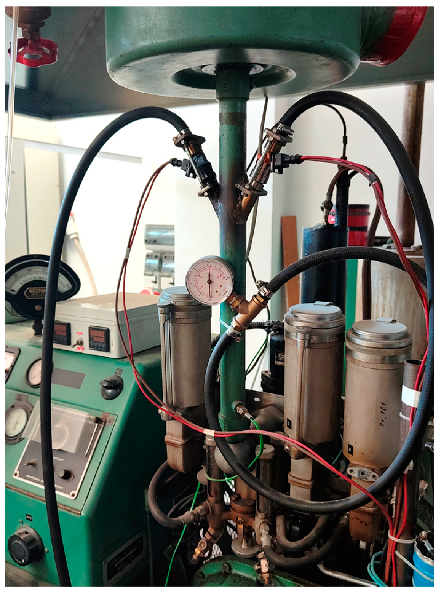
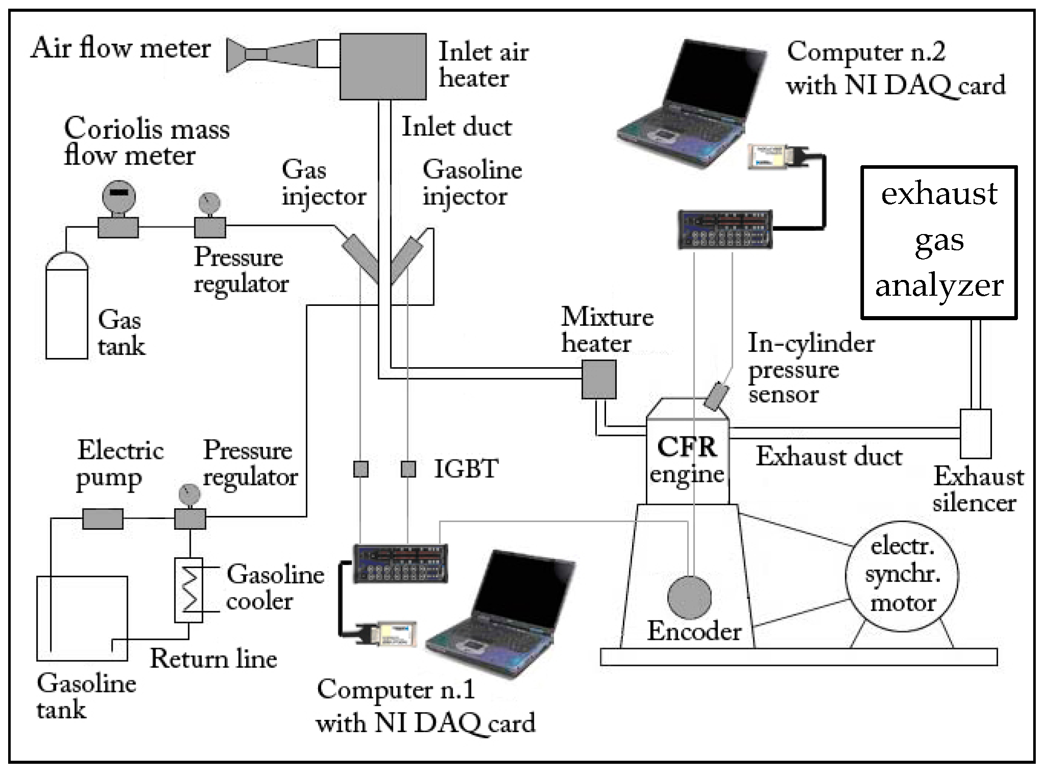
2.1. Experimental Setup

The engine employed in this work is a standard CFR S.I. engine [22] used to measure the octane number of liquid fuels.
Because the engine set-up and the measuring equipment have been widely described in previous works by the same authors [23,24,25], only a brief description will be given here. The CFR is a single cylinder, two-valve, variable CR, four-stroke SI engine. Its main specifications are reported in Table 2.
By moving the cylinder head, the CR of the engine can be adjusted over a wide range. The original CFR was modified by implementing two separate electronic injection systems (as reported in Figure 1) in order to be able to control the amount of gasoline or gaseous fuel injected and to obtain mixtures with different A/F ratios. In the test performed, both air and fuel were measured with proper mass flow meters. The in-cylinder pressure was measured by a piezoelectric sensor flush mounted on the combustion chamber whereas the piston position was evaluated by using an optical encoder connected to the engine crankshaft. The in-cylinder pressure sensor was also used to detect knocking, as described in [23]. An exhaust-gas analyzer was used to measure the NOx (ppm), unburned hydrocarbons HC (ppm), carbon monoxide CO (%vol.) and carbon dioxide CO2 (%vol.).
Table 3 reports the accuracies of the measurement equipment used in the tests.
Figure 2 shows a scheme of the experimental layout.

2.2. Test Execution and Data Manipulation

The above-described CFR engine, fueled with hydrogen, was used to perform a series of experimental test: the engine CR and A/F ratio was varied in a wide range and the corresponding pressure curves were acquired. The cylinder pressure was used to evaluate, by means of the Rassweiler and Withrow method [26], the experimental MFB curve in order to highlight the different phases of combustion (laminar and turbulent).
The cylinder pressure was used also to evaluate the engine indicated thermal efficiency (ITE):
I T E = P I N D G F · L H V
being PIND the indicated power, LHV the fuel lower calorific value, and GF the measured fuel mass flow; the indicated power was obtained by means of engine speed n, engine displacement V and net indicated mean effective pressure (IMEP):
P I N D = I M E P · V · n 120
The IMEP, in turn, was evaluated integrating the experimental pressure as a function of the in-cylinder volume:
I M E P = 0 720 p · d V V · N c y l
where Ncyl is the number of cylinders.
As is known, ITE may be considered the product of two different efficiencies that take into account different energy loss phenomena. The first is the ideal thermodynamic cycle efficiency that, in the case of SI engine, is the Otto cycle whose efficiency is:
η O t t o = 1 1 ( C R ) k 1
where k is the isentropic coefficient equal to 1.4 for air.
Besides incomplete combustion, there are two other significant phenomena that reduce the thermodynamic efficiency: heat loss to the combustion chamber wall and non-isochoric combustion. These effects are represented by the internal efficiency ηi as follows.
η i = I T E / η O t t o
In this way, a qualitative comparison between the different operating conditions in terms of heat losses can be performed because these are inversely proportional to the internal efficiency.
As most of the heat losses occur during combustion and are proportional to the burning mixture temperature, in the aforementioned comparison it is useful to evaluate the average combustion temperature T′c. The generic combustion temperature Tc, as a first and very large approximation, can be evaluated by means of the perfect gas law with the following equation:
T c = P c V c T I V C P I V C V I V C
where TIVC, PIVC and VIVC are the measured temperature, pressure and volume, respectively, at inlet valve closure (IVC). Pc and Vc are the generic, experimentally measured pressure and volume during combustion. T′c is the average Tc evaluated during the whole combustion duration from SA to 100% MFB CA.
The aforementioned approximation assumes that all the mass within the cylinder is involved in the combustion process at the same temperature Tc. However, in reality, two different masses should be considered: the burned and unburned gases. These gases follow distinct processes where the burned mass experiences a significant temperature increase and expansion due to combustion heat, whereas the unburned mass undergoes an almost adiabatic compression and limited temperature increase. Although they share the same pressure, these two masses have distinct temperatures and occupy different volumes within the cylinder. However, this scenario can be evaluated only by means of two-zone combustion models that are beyond the scope of this work. For a rough and qualitative comparison of the heat lost during combustion, T′c can be evaluated using the perfect gas law. To continue, the heat loss analysis consists in evaluating the experimental ITE for all the operating conditions tested, calculating the ηi, and qualitatively evaluating and comparing the amount of heat loss that is inversely proportional to ηi. The T′c evaluated in the different operating conditions is very useful during the qualitative heat loss comparison because it can highlight the role of both convective heat transfer coefficient and thermal boundary layer.
A test performed with stoichiometric gasoline–air mixture and engine CR equal to 6.5 was used as a reference operating condition to compare all the results obtained with hydrogen and to highlight the main differences (pro and cons) between a conventional and an innovative fuel. In all of the aforementioned experiments, the SA was adjusted to achieve a location of peak pressure (LPP) approximately 15 CAD after top dead center (ATDC), which is a commonly used indicator of optimal combustion phase, as reported by Heywood [27].
Table 4 resumes all the operating parameters used in the mentioned tests; in this table the spark advance (SA) is expressed in CAD before top dead center (BTDC).
During all the mentioned tests the engine pollutant emissions were measured.

3. Results and Discussion

A preliminary test was performed by varying the engine CR and finding the minimum λ value that allows a knock-free operation. The CR was varied between 4.75 and 13.5 and the corresponding λ value between 1.30 and 1.94. This test enables the measurement of knock resistance, which is indicated by the engine CR, for various lean hydrogen mixtures. This provides valuable initial guidance to engine designers about the maximum engine CR or minimum λ that can be used for knock-free operation. Obviously, to apply this method, a proper match between CFR and actual engine compression ratios must be defined. To this purpose, the authors experimentally determined that a CFR CR equal to 6.5 may correspond to a CR equal to 10 in a smaller displacement cylinder (310.5 cm3) of a series production automotive engine, as both cylinders produce incipient knocking at full load and at the same mean piston speed (3.43 m/s) if the maximum brake torque SA is adopted together with a stoichiometric gasoline–air mixture.
The results, shown in Figure 3, show a linear dependence between the two parameters. This means that, unlike gasoline, the leaner hydrogen–air mixtures exhibit an increased knock resistance.
This behavior can be explained with the different processes that lead the two fuels to knock. In gasoline–air mixtures, the knocking is mainly caused by the expiration of the auto-ignition time delay whose duration depends on the pressure and temperature. This enriches the mixture and increases the combustion speed and, in turn, allows the flame front to burn all the gasoline–air mixtures before the auto-ignition time expires. On the other hand, the stoichiometric hydrogen–air mixture is very reactive, and its minimum ignition energy is very small [7] (Table 1); consequently, the auto-ignition phenomena are often triggered by hot spots inside the combustion chamber. The increase in mixture A/F ratio greatly reduces both its reactivity and the end-gas temperature during combustion and, in turn, knock occurrence.
Through extrapolating the diagram in Figure 3, it can be concluded that a CFR engine having a CR of approximately 14 can operate with a hydrogen-air mixture of λ = 2. This seems a perfectly acceptable hypothesis given that the difference between a CR of 14 and 13.5 is less than 4%. The substantial increase in the CFR CR from 4.75 to 14, which corresponds to an increase in λ from 1.3 to 2, indicates that an automotive SI engine fueled with hydrogen and operated at λ = 2 could potentially employ a significantly higher CR than current engines without experiencing knock, resulting in a significant improvement in thermodynamic efficiency.
In order to highlight the effects of λ on combustion duration, a second set of tests was performed with a fixed CR of 6.5 and a variation in the hydrogen–air mixture λ from 1.5 to 2.5. To this purpose, the experimental pressure curves were manipulated to obtain the experimental MFB curves. The combustion was divided in three parts. First is the flame front development phase, which is mainly characterized by laminar flame speed propagation and ranges from spark timing to the CA corresponding to 5% of MFB. Second is the rapid combustion phase, delimited between 5% and 90% of MFB, which is often referred to as the actual combustion duration because the heat released during this phase produces the main effects on the thermodynamic engine cycle. The final 10% of the combustion duration, from 90% to 100% of MFB, is marked by flame quenching and is disregarded due to its negligible thermodynamic impacts and potential to introduce uncertainty regarding the actual cessation of combustion. Both flame front development phase (0–5% of MFB) and rapid combustion phase (5–90% of MFB) were evaluated as function of λ at constant CR (6.5).
In addition, by merging the first and second dataset, it was possible to determine the dependency between combustion duration and CR at constant λ.
In Figure 4, the duration of flame front development (a) and rapid combustion (b) are presented for two main datasets: one with a variable CR and the other with a constant CR of 6.5. The durations are plotted as a function of λ and are compared with the reference condition of gasoline stoichiometric. The flame front development duration, characterized by laminar flame propagation speed, increases almost linearly with λ, but the dataset with variable CR shows a lower slope. This can be explained considering that higher CR produces higher pressure and temperature at the ignition time and, in turn, higher laminar flame speed [16]. The gasoline stoichiometric combustion exhibits a much higher flame front development duration compared to hydrogen and this reflects its lower laminar flame speed [16]. The above results are coherent with other findings in the literature [21].
The rapid combustion duration, characterized by turbulent flame propagation speed, increases almost linearly with λ for the dataset with constant CR and more than linearly for the dataset with variable CR. This suggests that an increase in CR hampers turbulent combustion and further lengthens it. Moreso, in this case, the gasoline–stoichiometric mixture exhibits a longer rapid combustion phase compared with hydrogen except for λ = 2.5 and CR = 6.5.
In order to better highlight the influence of CR on the combustion phases duration, three couples of operating conditions were selected; each couple being identified by the same λ (and different CR). In Figure 5, the duration of both the flame front development phase (a) and the rapid combustion phase (b) are shown, for the three couples of operating conditions considered.
Figure 5a shows a decreasing trend of flame front development duration when increasing CR and this effect, as already stated, is due to the increment of pressure and temperature at the end of compression stroke that increases laminar flame speed; on the other hand, Figure 5b shows the trend of rapid combustion with CR and here a slight increase can be noted, in particular at higher λ values. This result contrasts with the findings in the literature [21], where both laminar and turbulent combustion phases decrease with increasing CR.
It can be concluded that CR has a strong reducing effect on flame front development and a weak increasing effect on rapid combustion whereas λ has an increasing effect on both combustion phases.
To give an overall view, the duration of the main part of the combustion, i.e., from spark timing to 90% of MFB, was plotted in Figure 6 as a function of λ (a) and as a function of CR (b).
Figure 6a shows an almost linear increasing trend of the main combustion duration as function of λ regardless of the dataset, variable or constant CR, and this means that the effect of λ on the duration of flame front development (Figure 4a) is roughly balanced by the effect on rapid combustion phase (Figure 4b). Figure 6b instead shows a slightly decreasing trend of the main combustion duration as function of CR; this means that the effect of CR on flame front development (Figure 5a) is greater than that on rapid combustion (Figure 5b). Compared with gasoline, hydrogen produces a shorter combustion duration, closer to the isochoric process, even with very lean mixtures, which improves the engine’s thermodynamic efficiency.
As stated in previous section, the CFR raw emissions were measured in all the operating conditions of Table 4. The only relevant pollutant emitted by the hydrogen-fueled CFR engine was NOx, except for a very small amount of unburned hydrocarbons due to the engine lubricant, so it is very important to find the low NOx operating conditions.
Figure 7 clearly shows that for λ > 1.4 the NOx levels are lower than the gasoline ones and around λ = 1.9 the measured NOx are near zero (30–40 ppm) confirming that to obtain a “zero emissions” hydrogen engine it is required to adopt A/F ratios double than stoichiometric, as widely described in the literature [5,18,19,20]. The engine CR has no effect on the emitted NOx as is clearly visible by the perfect overlap between the two curves of Figure 7.
Finally, Figure 8a shows the effects of CR and λ on ITE and Figure 8b the effects on internal efficiency, which has an inversely proportional trend with respect to the heat transfer with the chamber wall and to the combustion duration, as already stated earlier.
Figure 8a highlights that, except for the operating condition with λ = 1.35 and CR = 5.5, hydrogen-fueled CFR always exhibits a higher ITE with respect to the gasoline counterpart and this is the combined result of the faster combustion (Figure 6a), the higher CR (in the case of dataset labelled “variable CR”) and the yet-be-confirmed effects of the heat transferred to the chamber walls. To actually determine the effects of heat loss, the ηi (Figure 8b) must be considered, as this eliminates the effect of CR and takes into account only the effects of both heat transfers and non-isochoric combustion. The dataset with “variable CR” shows in Figure 8b a lower ηi compared to gasoline, despite the shorter combustion (Figure 6a), clearly evidencing the higher heat losses.
To further investigate this aspect, the average combustion temperature T′c was evaluated, as stated in Section 2.2, and reported in Table 4. Despite the hydrogen dataset with “variable CR” exhibiting lower values of T′c (around 1000 K) compared to gasoline (around 1200 K), it also shows higher heat loss, evidenced by the lower ηi, and this is due to the higher thermal diffusivity of the hydrogen flame and to the smaller quenching distance that produces a thinner thermal boundary layer and, in turn, higher thermal flux to chamber walls. The higher heat loss of hydrogen combustion with respect to conventional hydrocarbons is widely reported in the literature [5,7,17].
In order to highlight the effects of λ on the heat loss of hydrogen combustion, the dataset labeled “CR = 6.5” reported Figure 8b must be considered. The diagram shows an almost constant trend indicating that the negative effect of combustion duration increase (Figure 6a) is balanced by the positive effect of the reduced heat loss due to the decreasing T′c (last six rows of Table 4); for λ = 2.5 the negative effect dominates and ηi equals the gasoline one.
Figure 9 shows the great reducing effect of CR on ηi at constant λ and the main reasons are as followed. On the one hand, the operating conditions with higher CR in Figure 9 exhibit higher T′c (Table 4) and this contributes to increase the heat transfer; on the other hand, the higher CR amplifies the tumble motion breakdown, as reported by Falfari et al. [28]. This phenomenon promotes the in-cylinder turbulence that increases the convective coefficient and, in turn, the heat exchanges. The three segments in Figure 9 exhibit different slopes evidencing the combined effect of CR and λ. In particular, an increase in λ mitigates the effect of CR slightly reducing the heat exchanges and increasing the internal efficiency.

4. Conclusions

In this paper, the combustion of hydrogen in a CFR engine was analyzed in order to assess the effects of engine CR and mixture λ on both combustion speed and heat loss to the chamber wall. The combustion was divided in two parts: the first (flame front development phase) characterized by laminar flame speed and the second (rapid combustion phase) characterized by turbulent flame speed. The tests show the following results:
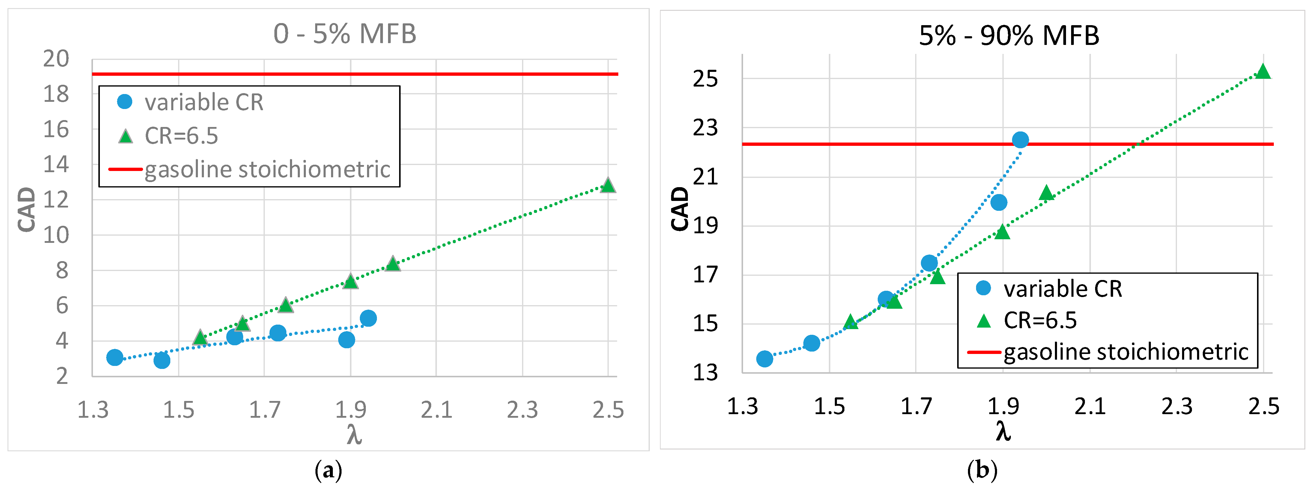
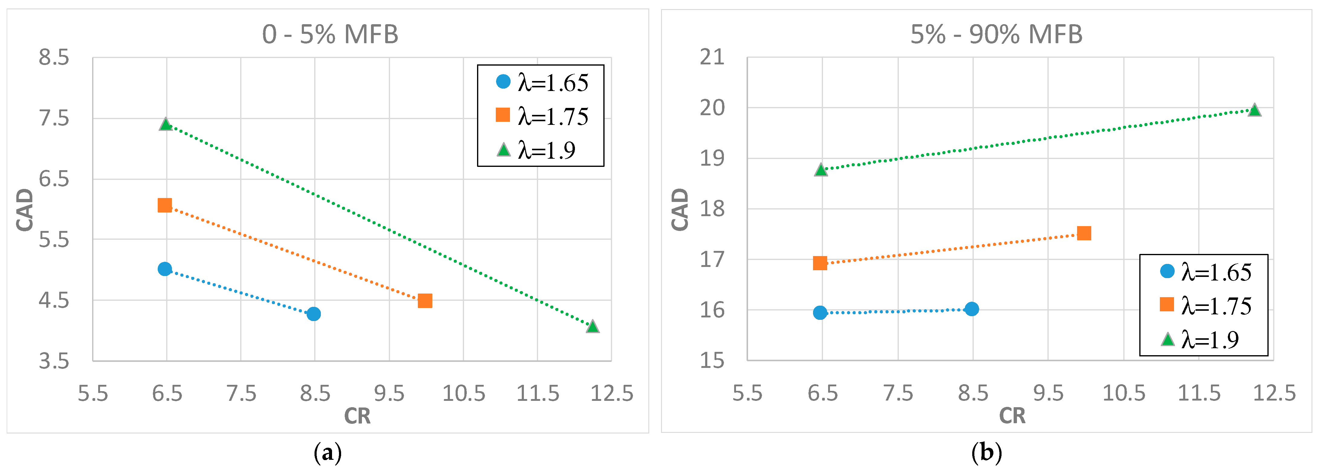
  • Increasing λ produces an increasing effect on the duration of both combustion parts;
  • Increasing CR produces a decrease of the laminar combustion duration and a slight increase in the turbulent one;
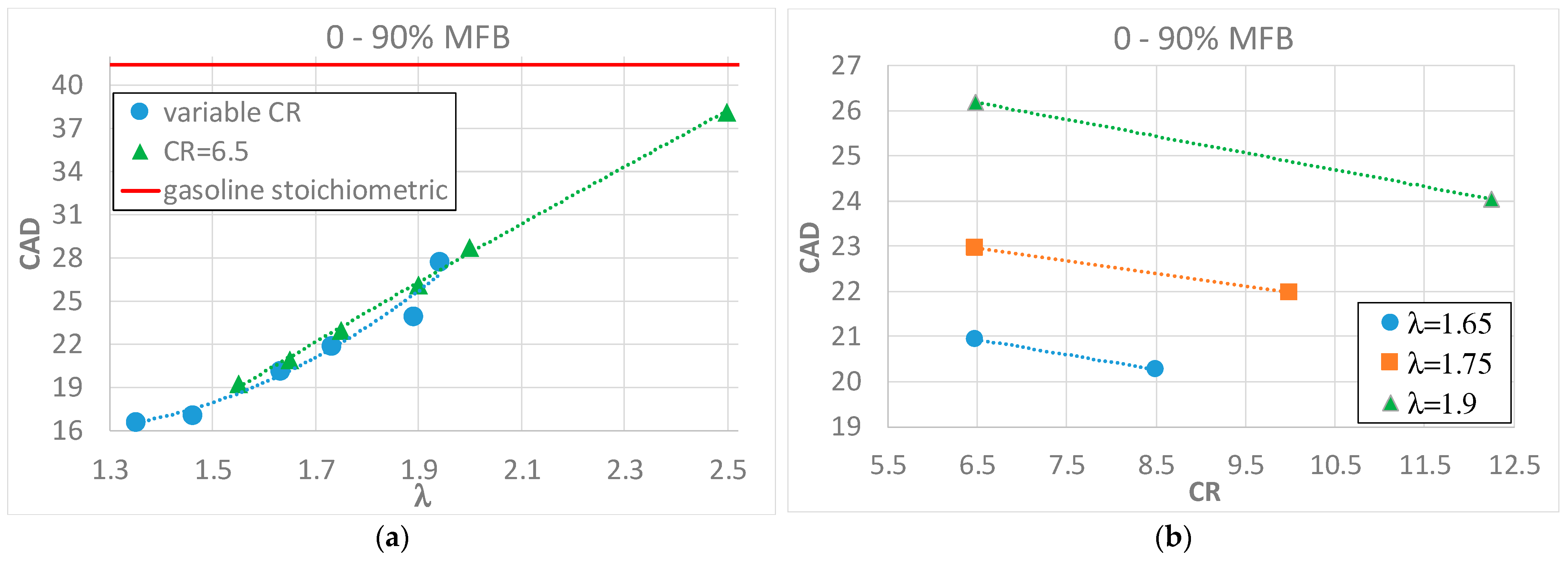
  • The whole combustion duration undergoes an increasing effect by λ and a decreasing effect by CR;
  • The heat loss to the combustion chamber wall undergoes a slight reduction by increasing λ (due to the combustion temperature reduction) and a great increase by increasing CR (due to the increase of both combustion temperature and convective heat transfer);
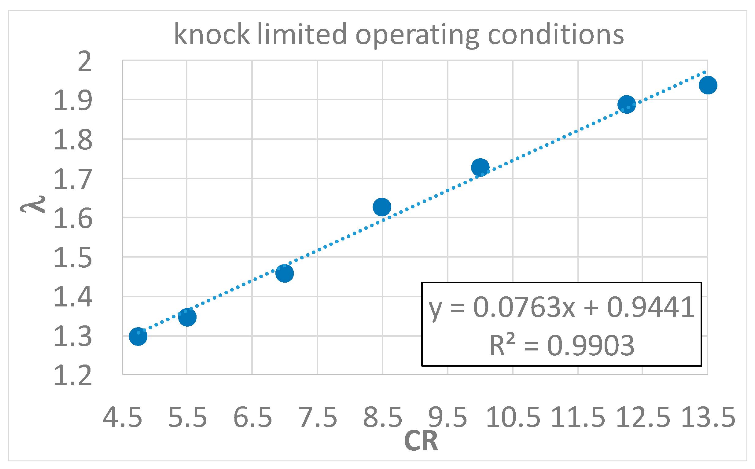
  • An experimental correlation between CR and λ was determined, in order to obtain knock-free operating conditions, and a linear trend between the two parameters was found.
The raw NOx emissions were also measured.
All the mentioned results were compared with a reference operating condition obtained fueling the CFR with stoichiometric air–gasoline mixture. The results of this comparison are:
  • Hydrogen combustion always shows a shorter duration with respect to gasoline combustion, in both the laminar and the turbulent part;
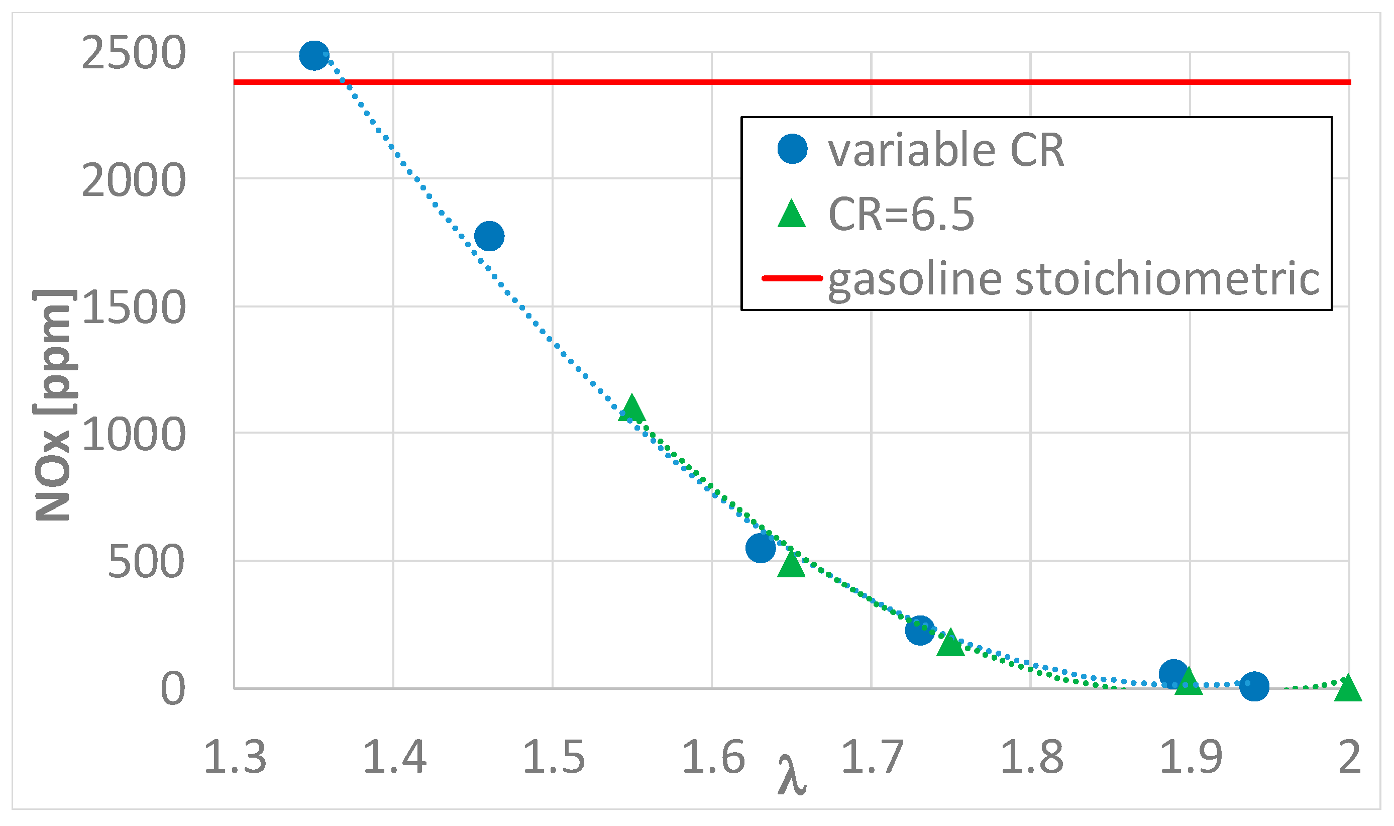
  • For λ > 1.4, the NOx levels are lower than the gasoline ones and for λ > 1.9, the measured NOx are near zero;
  • The heat transfer to the chamber wall is higher when fueling with hydrogen with respect to gasoline operation in particular for higher CR.
The above results confirm the findings mentioned in the literature [17,21] and also provide some new results: in [21] the engine CR was varied between 4.5 and 7.2 and the λ ratio between 1.25 and 2; whereas, in the present work, the engine CR was varied between 4.75 and 13.5 and the λ ratio between 1.3 and 2.5. In [17], the authors, using a SI engine with fixed CR, explored the effects of hydrogen A/F ratio on heat exchanges with the chamber wall; however, in the present work, the effects of both A/F ratio and engine CR on heat exchanges were explored.
It can be concluded that hydrogen allows, with proper λ values, a faster and cleaner combustion compared to gasoline with higher CR and consequently higher engine efficiency. These considerations identify green hydrogen as the most promising substitute for conventional fossil fuels in the modern automotive market.

Author Contributions

Conceptualization, S.B., S.C. and E.P.; Data curation, S.B. and S.C.; Formal analysis, S.B. and S.C.; Investigation, S.B. and S.C.; Methodology, S.B. and E.P.; Supervision, E.P.; Validation, E.P.; Writing—original draft, S.B.; Writing—review & editing, E.P. All authors have read and agreed to the published version of the manuscript.

Funding

This research and the related APC were funded by the University of Palermo—Italy, “Call for research projects developed by individual researchers” protocol n. 7666-01/10/2021, fund granted by DD n. 466/2021.

Data Availability Statement

Not applicable.

Conflicts of Interest

The authors declare no conflict of interest. The funders had no role in the design of the study; in the collection, analyses, or interpretation of data; in the writing of the manuscript; or in the decision to publish the results.

References

  1. Shu, X.; Guo, Y.; Yang, W.; Wei, K.; Zhu, G. Life-cycle assessment of the environmental impact of the batteries used in pure electric passenger cars. Energy Rep. 2021, 7, 2302–2315. [Google Scholar] [CrossRef]
  2. Picatoste, A.; Justel, D.; Mendoza, J.M.F. Circularity and life cycle environmental impact assessment of batteries for electric vehicles: Industrial challenges, best practices and research guidelines. Renew. Sustain. Energy Rev. 2022, 169, 112941. [Google Scholar] [CrossRef]
  3. Mazzeo, D.; Herdem, M.S.; Matera, N.; Wen, J.Z. Green hydrogen production: Analysis for different single or combined large-scale photovoltaic and wind renewable systems. Renew. Energy 2022, 200, 360–378. [Google Scholar] [CrossRef]
  4. Lee, H.; Choe, B.; Lee, B.; Gu, J.; Cho, H.S.; Won, W.; Lim, H. Outlook of industrial-scale green hydrogen production via a hybrid system of alkaline water electrolysis and energy storage system based on seasonal solar radiation. J. Clean. Prod. 2022, 377, 134210. [Google Scholar] [CrossRef]
  5. White, C.M.; Steeper, R.R.; Lutz, A.E. The hydrogen-fueled internal combustion engine: A technical review. Int. J. Hydrog. Energy 2006, 31, 1292–1305. [Google Scholar] [CrossRef]
  6. Verhelst, S. Recent progress in the use of hydrogen as a fuel for internal combustion engines. Int. J. Hydrog. Energy 2014, 39, 1071–1085. [Google Scholar] [CrossRef] [Green Version]
  7. Verhelst, S.; Wallner, T. Hydrogen-fueled internal combustion engines. Prog. Energy Combust. Sci. 2009, 35, 490–527. [Google Scholar] [CrossRef] [Green Version]
  8. Saafi, M.A.; Ou, S.; Jiang, Y.; Li, H.; He, X.; Lin, Z.; Gan, Y.; Lu, Z.; Dawson, S.T.M. Exploring the potential of hydrogen in decarbonizing China’s light-duty vehicle market. Int. J. Hydrog. Energy 2022, 47, 36355–36371. [Google Scholar] [CrossRef]
  9. Sopena, C.; Diéguez, P.M.; Sáinz, D.; Urroz, J.C.; Guelbenzu, E.; Gandía, L.M. Conversion of a commercial spark ignition engine to run on hydrogen: Performance comparison using hydrogen and gasoline. Int. J. Hydrog. Energy 2010, 35, 1420–1429. [Google Scholar] [CrossRef]
  10. Keller, J.; Lutz, A. Hydrogen Fueled Engines in Hybrid Vehicles. SAE Trans. 2001, 110, 481–486. Available online: http://www.jstor.org/stable/44724324 (accessed on 26 February 2023).
  11. Wang, Y.; Biswas, A.; Rodriguez, R.; Keshavarz-Motamed, Z.; Emadi, A. Hybrid electric vehicle specific engines: State-of-the-art review. Energy Rep. 2022, 8, 832–851. [Google Scholar] [CrossRef]
  12. Arat, H.T. Simulation of diesel hybrid electric vehicle containing hydrogen enriched CI engine. Int. J. Hydrog. Energy 2019, 44, 10139–10146. [Google Scholar] [CrossRef]
  13. Arat, H.T. Alternative fuelled hybrid electric vehicle (AF-HEV) with hydrogen enriched internal combustion engine. Int. J. Hydrog. Energy 2019, 44, 19005–19016. [Google Scholar] [CrossRef]
  14. He, X.; Maxwell, T.; Parten, M.E. Development of a Hybrid Electric Vehicle With a Hydrogen-Fueled IC Engine. IEEE Trans. Veh. Technol. 2006, 55, 1693–1703. [Google Scholar] [CrossRef]
  15. Nakajima, Y.; Yamane, K.; Shudo, T.; Hiruma, M.; Takagi, Y. Research and Development of a Hydrogen-Fueled Engine for Hybrid Electric Vehicles. SAE Trans. 2000, 109, 1175–1179. Available online: http://www.jstor.org/stable/44634296 (accessed on 26 February 2023).
  16. Dahoe, A.E. Laminar burning velocities of hydrogen–air mixtures from closed vessel gas explosions. J. Loss Prev. Process Ind. 2005, 18, 152–166. [Google Scholar] [CrossRef]
  17. Shudo, T.; Nakajima, Y.; Futakuchi, T. Thermal efficiency analysis in a hydrogen premixed combustion engine. JSAE Rev. 2000, 21, 177–182. [Google Scholar] [CrossRef]
  18. Nagalingam, B.; Dübel, M.; Schmillen, K. Performance of the Supercharged Spark Ignition Hydrogen Engine; SAE Technical Paper 831688; SAE International: Warrendale, PA, USA, 1983. [Google Scholar] [CrossRef]
  19. Berckmüller, M.; Rottengruber, H.; Eder, A.; Brehm, N.; Elsässer, G.; Müller-Alander, G.; Schwarz, C. Potentials of a Charged SI-Hydrogen Engine; SAE Technical Paper 2003-01-3210; SAE International: Warrendale, PA, USA, 2003. [Google Scholar] [CrossRef]
  20. Natkin, R.; Tang, X.; Boyer, B.; Oltmans, B.; Denlinger, A.; Heffel, J.W. Hydrogen IC Engine Boosting Performance and NOx Study; SAE Technical Paper 2003-01-0631; SAE International: Warrendale, PA, USA, 2003. [Google Scholar] [CrossRef]
  21. Salvi, B.L.; Subramanian, K.A. A novel approach for experimental study and numerical modeling of combustion characteristics of a hydrogen fueled spark ignition engine. Sustain. Energy Technol. Assess. 2022, 51, 101972. [Google Scholar] [CrossRef]
  22. ASTM Standard D2700; Standard Test Method for Motor Octane Number of Spark Ignition Engine Fuel. ASTM International: West Conshohocken, PA, USA, 2022. [CrossRef]
  23. Beccari, S.; Pipitone, E.; Genchi, G. Knock onset prediction of propane, gasoline and their mixtures in spark ignition engines. J. Energy Inst. 2016, 89, 101–114. [Google Scholar] [CrossRef]
  24. Beccari, S.; Pipitone, E.; Genchi, G. Calibration of a Knock Prediction Model for the Combustion of Gasoline-LPG Mixtures in Spark Ignition Engines. Combust. Sci. Technol. 2015, 187, 721–738. [Google Scholar] [CrossRef]
  25. Pipitone, E.; Beccari, S. A Comprehensive Model for the Auto-Ignition Prediction in Spark Ignition Engines Fueled With Mixtures of Gasoline and Methane-Based Fuel. J. Eng. Gas Turbines Power 2019, 141, 041009. [Google Scholar] [CrossRef]
  26. Rassweiler, G.; Withrow, L. Motion Pictures of Engine Flames Correlated with Pressure Cards; SAE Technical Paper 380139; SAE International: Warrendale, PA, USA, 1938. [Google Scholar] [CrossRef]
  27. Heywood, J.B. Internal Combustion Engine Fundamentals; McGraw-Hill: New York, NY, USA, 1988. [Google Scholar]
  28. Falfari, S.; Brusiani, F.; Pelloni, P. 3D CFD Analysis of the Influence of Some Geometrical Engine Parameters on Small PFI Engine Performances—The Effects on the Tumble Motion and the Mean Turbulent Intensity Distribution. Energy Procedia 2014, 45, 701–710. [Google Scholar] [CrossRef] [Green Version]
Figure 1. Modified CFR injection system.
Energies 16 02351 g001
Figure 2. Experimental layout.
Energies 16 02351 g002
Figure 3. Knock-free minimum λ as function of the CR.
Energies 16 02351 g003
Figure 4. Two combustion phases, for all the tested operating conditions, as a function of λ. (a) Flame front development and (b) rapid combustion.
Energies 16 02351 g004
Figure 5. Duration of flame front development and rapid combustion as a function of CR at constant λ. (a) Flame front development and (b) rapid combustion.
Energies 16 02351 g005
Figure 6. Duration of main part of combustion as a function of both λ and CR. (a) Main combustion duration as function of λ and (b) main combustion duration as function of CR.
Energies 16 02351 g006
Figure 7. NOx emissions of the hydrogen-fueled CFR as a function of λ.
Energies 16 02351 g007
Figure 8. The indicated (a) and internal (b) efficiencies as a function of λ. (a) CFR ITE as function of λ and (b) CFR ηi as function of λ.
Energies 16 02351 g008
Figure 9. Internal efficiency as a function of CR at constant λ.
Energies 16 02351 g009
Table 1. Hydrogen properties (at 300 K and 1 atm) compared with methane and isooctane (the fuel–air mixtures are stoichiometric) [7,16].
SpecificationH2CH4C8H18H2-AirCH4-AirC8H18-Air
laminar flame speed at 360 K [cm/s]---2904845
lower heating value [MJ/kg]1205044.3---
density [kg/m3]0.080.65692---
volumetric energy content [kJ/m3]---318930413704
minimum ignition energy [mJ]---0.020.280.28
adiabatic flame temperature [K]---239022262276
minimum quencing distance [mm]---0.642.033.5
stoichiometric air-fuel ratio [kg/kg]34.217.115---
flammability limits (λ)10–0.142–0.61.51–0.26---
Table 2. CFR engine specifications.
SpecificationValue
ManufacturerDresser waukesha
ModelF1/F2 Octane
Compression ratio4.5–16
Inlet mixture temperaturevariable
Spark advancevariable
Bore82.6 [mm]
Stroke114.3 [mm]
Connecting rod length254.0 [mm]
Displacement611.2 [cm3]
Speed (fixed)900 [rpm]
Table 3. Accuracy of the instrumentation used in the tests.
SensorAccuracy
Gasoline mass flow meter±1% of reading
Hydrogen mass flow meter±1% of reading
Air mass flow meter±1% of reading
Combustion chamber pressure sensorlinearity error < ±0.3% FSO
Combustion chamber pressure sensorthermal sensitivity shift < ±0.5% at temperature between 200 and 300 °C
NOx sensor±4% or 25 ppm absolute
Table 4. Operating parameters.
FuelA/F Mixture Inlet Temperature (°C)Engine CRλSA (CAD BTDC)Average Combustion Temperature T′c [K]
gasoline426.51.00251237
hydrogen434.751.351053
hydrogen435.51.3541037
hydrogen437.01.4641060
hydrogen448.51.6351030
hydrogen4410.01.7351022
hydrogen4412.31.896982
hydrogen4513.51.943951
hydrogen446.51.5541034
hydrogen446.51.6571006
hydrogen456.51.759973
hydrogen456.51.9012945
hydrogen456.52.0015916
hydrogen456.52.5021835
Disclaimer/Publisher’s Note: The statements, opinions and data contained in all publications are solely those of the individual author(s) and contributor(s) and not of MDPI and/or the editor(s). MDPI and/or the editor(s) disclaim responsibility for any injury to people or property resulting from any ideas, methods, instructions or products referred to in the content.

