Article

Design and Optimization of a Magnetic Field Exciter for Controlling Magnetorheological Fluid in a Hybrid Soft-Rigid Jaw Gripper

by
Marcin Białek
1,* and
Cezary Jędryczka
2,*
1
Division of Mechatronic Devices, Institute of Mechanical Technology, Poznan University of Technology, 60-965 Poznan, Poland
2
Division of Electrical Machines and Mechatronics, Institute of Electrical Engineering and Electronics, Poznan University of Technology, 60-965 Poznan, Poland
*
Authors to whom correspondence should be addressed.
Energies 2023, 16(5), 2299; https://doi.org/10.3390/en16052299
Submission received: 1 February 2023 / Revised: 20 February 2023 / Accepted: 24 February 2023 / Published: 27 February 2023

Abstract

:
The paper deals with an optimization of a magnetic circuit of the field exciter designed to control magnetorheological fluid (MRF) in a hybrid soft–rigid jaw gripper. The case discussed includes sealing of the MRF inside a cushion made of thermoplastic polyurethane (TPU). The shear stress distributions in the MRF upon magnetic field excitation have been analyzed for various permanent magnet, yoke, and air gap dimensions. In the developed numerical model of the magnetic field exciter, the geometry of the considered domain was parameterized. As part of the simulation study, more than 4600 variants of the magnetic circuit were analyzed, for which the shear stress distribution in the MRF inside the cushion was determined. The numerical model has been implemented in the Ansys Electronics Desktop 2020 finite element method (FEM) package. Research was focused on finding dimensions of the magnetic circuit that ensure the desired distribution of the shear stress in the MRF inside the cushion. The undeformed and deformed by axial plunging of the pin cushions geometries have been analyzed. The evaluation criteria were the achievement of the highest possible value of the shear stress and the uniformity of its distribution in the given cross-sectional area of the MRF inside the cushion. The main objective of the analysis was to design the magnetic field exciter for application in the jaw pads of a gripper using MRF cushions. Through research, a suitable configuration tailored to the needs of the application was proposed.

1. Introduction

The continued interest in new robotic gripper structures is generating further iterations of new solutions based on pneumatics [1,2] and mechanically driven jaws [3,4]. Experimental studies comparing commercially available devices are also essential [5]. Soft structures have become popular, allowing them to adapt to the surface and shape of the gripped object. At the same time, they have limitations on the generated forces and the lifting capacity compared to rigid structures with fewer degrees of freedom [6]. Therefore, attention is currently focused on the development and implementation of hybrid structures consisting of rigid and soft elements. They are designed to integrate the advantages of both approaches into a single versatile device with enhanced structural adaptation properties and the ability to manipulate a wide range of objects in terms of shape, size, and mass. One approach is to use silicone soft pads in the classic hand prosthesis structure [7]. Another solution studied is the use of air-filled membranes that provide softness to the jaw [8]. Particularly interesting is the study of the adaptation of their structure to the grasped object. Compared to rigid jaws with defined geometry, they have added the ability to fill the free space between structures and thus increase the contact area between the two components. In the design process, the authors of the mentioned research used FEM analysis. Another solution is based on a gel–silicone structure placed on the jaws of the gripper in the form of cushions [9,10]. The volume of gel inside the pad is adjustable and adaptable depending on the structure of the gripped object. Jamming gripper-based structures [11,12] are among these solutions at the same time. The subject of this article specifically covers the application of magnetorheological fluids in the soft–rigid structures of robotic grippers [13]. An extension taken from the jamming grippers is the use of magnetorheological fluid (MRF) instead of granular [14,15]. The change in its viscosity depends on the supply current of an electromagnet located at the base of the vessel [16]. An additional aspect tested was the interference with the structure of the MRF itself through the addition of nonmagnetic particles that thicken the colloidal compound, intensifying its stiffening effect upon exposure to a magnetic field. The next iteration was to reduce the dimensions of the cushion and place them on parallel chuck jaws [17]. The insertion of the magnetic field into the volume of the MRF vessel is performed through a belt-geared mechanism and a pull screw, and the source is a permanent magnet with a yoke. In this case, the authors also used an MRF enhanced with carbon microbeads. At the same time, it is worth noting that research is being carried out on progressive magnetic field source designs for gripper applications using MRFs [18]. Regarding the use of magnetorheology, it is also worth pointing out studies of the use of magnetorheological elastomer (MRE) in grippers [19,20]. Since the functional parameters of the gripper depend on its stiffness controlled by the change in the MRF viscosity, precise methods for modelling magnetic field distribution, such as FEM, are applied [21]. The article [22] presents the distribution of the magnetic field in a truncated cone bladder filled with MR fluid, with a design based on a jamming gripper. In addition, a study of the magnetic flux density along the axis of symmetry of the bladder above the face of the electromagnet is provided. In the article [23], FEM was used to correlate simulation data with experimental measurements of the real object to then perform a study of the magnetic flux density inside the core of the coil containing the MRF. In the aforementioned papers, FEM simulations have been used to represent the magnetic field distribution of the proposed gripper solutions or to study the behaviour of the MRF. However, they include a reflection of real conditions, which are difficult to measure with an apparatus. FEM is also used in the analysis of dampers [24,25], valves [26], or brakes [27,28] with MRF. The main consideration is the presence of a coil in most of these applications [22,23,24,25,26,27,28,29]. The aforementioned approaches present solutions using MRF, to which FEM analysis has been applied. However, it should be noted that the results presented cover only the final solution, implemented as part of the research conducted. Discussion and justification of the reasons for the implementation of certain device geometry and operating conditions are limited in terms of additional FEM analysis.
Figure 1 shows a classification of solutions using MRFs based on [6]. In addition to the proposed criteria, the authors included an axis that defines the subjective level of participation of the MRF in the grasping process. It can be partially identified with the second group classified within [30]. The higher the level, the greater the impact in the gripping process of changing the stiffness of the MR fluid on the gripper concerned. Due to the various forms of MRF application in grippers, the authors of the paper also introduced a form of classification of individual solutions due to the aspect of the design of the described devices. Based on [6], it is possible to recognise three general groups in term of gripping versatility and the ability to change the orientation of the object being held. These are jaw grippers, grippers based on a tentacle structure, and grippers based on a jamming gripper design. The fourth group that the authors of the article propose in this list is a set of solutions based on enhanced adhesion [31,32]. These are concerned with soft grippers (based on a tentacle structure) [33,34]. Among jaw grippers, an extreme division is evident in terms of participation of the degree of MRF in the gripping process. The solutions described in [35,36,37,38,39,40] have elements (such as clutches or pistons) in their construction. Due to their indirect participation in grasping objects, they were classified as devices with a low degree of participation of MRF in the grasping process. The other group are solutions based on jamming grippers [15,16,21,22,41]. Without the presence of the fluid, these solutions would not make sense, since the gripping properties of these devices are fully dependent on the phenomena that occurs when the stiffness of the MRF is increased by inserting a magnetic field. Therefore, they were placed at the end of the scale in question. By subjecting Figure 1 to further analysis, it is possible to recognise hybrid solutions. These are the ones that are simultaneously in at least two groups. These include, in particular, the solutions described in [14] and [17,21]. While [21] uses MR fluid indirectly through valves located outside the gripper tentacles, in [14,17] the MR fluid plays a very crucial role. The design of the jaws simultaneously allows for the action of pressure (actuation) on the object, and the soft cushions limit the movement of the grasped object by changing their stiffness. This area of Figure 1 is an embedded place in the classification of grippers, which is the focus of research in this article.
The Materials and Methods section presents the research object, which is the author’s gripper jaw, along with a description of the operating principle. In addition, the geometric parameters of the magnetic circuit discussed within the article are introduced as well as MRF used in simulations and conditions under consideration. Section 3 describes the results of the simulation studies, first introducing the results discussing, respectively, the influence of magnet thickness, analysis of parameters, and assessment of the stress distribution. The Discussion section then summarizes the presented research and selects magnetic circuit configurations in accordance with the established criteria. The article closes with the conclusion section that provides general observations on the work carried out. The objective approach resulted in the presentation of critical comments and outlooks on the proposed solution and the use of MR fluids in grippers.
Articles described in the Introduction inspired the authors of this article to conduct optimisation studies and consider other design options for a permanent magnet and yoke-based device as a source of controllable magnetic field in MRF based soft–rigid gripper. Simplifying the mechanics of the solution [17] and thoroughly studying the magnetic field exciter, which was still lacking, was the main goal of the authors of this article. A review of the literature showed a particular potential for carrying out and presenting the design calculations of a magnetic field exciter employing FEM. In particular, this concerns the shear stresses that occur in the volume of the cushion filled with MRF, which is crucial for this type of application [22,42,43,44]. More than 4600 variants of the magnetic circuit were analyzed for various configurations of permanent magnet, yoke, and air gap dimensions. For the above, the shear stress distribution that occurs in the MRF was determined. The research carried out on magnetic field exciter synthesis is applied with the Robotiq 2F-140 gripper design (Figure 2). The solution presented in this article is based on the design described in Polish patent application P.438636.

2. Materials and Methods

2.1. Research Object

The principle of operation of the proposed solution is illustrated in Figure 3. The change of the cushion stiffness (by means of the change of MRF fluid viscosity) is based on the use of magnetic field attraction and the spring reaction forces. Three phases of movement are specified (Figure 3). In Phase 1, the gripper jaws are directed at the object to be gripped. Closing the jaws reduces the distance between the pad and the edges of the object. The springs remain fixed, and the cushion is undeformed. Phase 2 involves plunging the pin and deformation of the cushion. The depth of the plunge is determined by the force of the clamping jaws. Further plunging causes an increase in force, which the springs take over in Phase 3, reducing the distance from the magnetic field exciter. Phase 3 ends with the closing of the air gap between the bottom of the cushion and the face of the permanent magnet. The main advantages of this solution are simplicity of operation, low energy cost, lack of coil, stability of operating temperature conditions, and in particular, lack of an additional control system for the magnetic field excitation. At the same time, the main objective of the application of stiffening the cushion structure after grasping the object is preserved. The release of the grip is conducted in reverse order from Phase 3 to Phase 1.

2.2. FEM Model of the Magnetic Circuit

The magnetic circuit considered by the authors provides a magnetic field that can be used to activate the MRF inside the cushion, as discussed in the paper [43,44]. It consists of a permanent magnet (N38 grade NdFeB), an air gap, and a ferromagnetic yoke (steel 1010). To determine the magnetic field distribution, a numerical model based on FEM has been developed in an Ansys Maxwell environment; the axial symmetry of the magnetic circuit has been assumed. The nonlinear magnetic properties of the MRF as well as ferromagnetic yoke have been taken into account. In order to determine distribution of the shear stress in MRF, the nonlinear rheological properties of the fluid have been implemented in the developed FE model as a postprocessing quantity based on the determined distribution of the magnetic field. The exemplary FE mesh plot, magnetic flux lines, and density plots, as well as distribution of the determined stress in the MRF are shown in Figure 4.
In order to enable optimization of the magnetic circuit, its geometry was parameterized. The introduced geometry parameters of the developed FE model are described in Figure 5 and Figure 6. They are defined as follows. The gm parameter is used to describe the thickness of the magnet, assuming a design space if gm is 2–8 mm (1 mm step). It is also assumed that the yoke at the base has a constant thickness of 2 mm (Figure 5). Figure 5 shows the other two important parameters in the study. The first is the diameter of the permanent magnet dpm, according to Formula (1), expressed by the kpm factor with values between 0.7 and 0.9 (0.05 step) (Figure 6). It represents the percentage of the diameter of the magnet in the diameter of the entire setup, which is 23.7 mm (the diameter 25 mm of the cushion base minus twice its thickness).
dpm = 23.7·kpm
From now on, kpm parameter will be used to describe the geometry of the studied magnetic circuit. The second parameter in the geometry represents the width of the yoke wj and thus the width of the air gap separating the yoke ring and the permanent magnet. It is described by Formula (3), which uses the width wr as half of the residual from subtracting the diameter of the whole setup and the diameter of the permanent magnet (described by Formula (2)).
wr = (23.7 − dpm)/2
wj = wr·kj
Due to the variability of dpm as a result of kpm, each time, the kj factor introduces an individual wj value within the configuration. The analyzed values of the kj factor according to Figure 6 are between 0.35 and 0.90 (0.05 step). The dpm and wj dimensions for each kj/kpm configuration are shown in Figure 6.

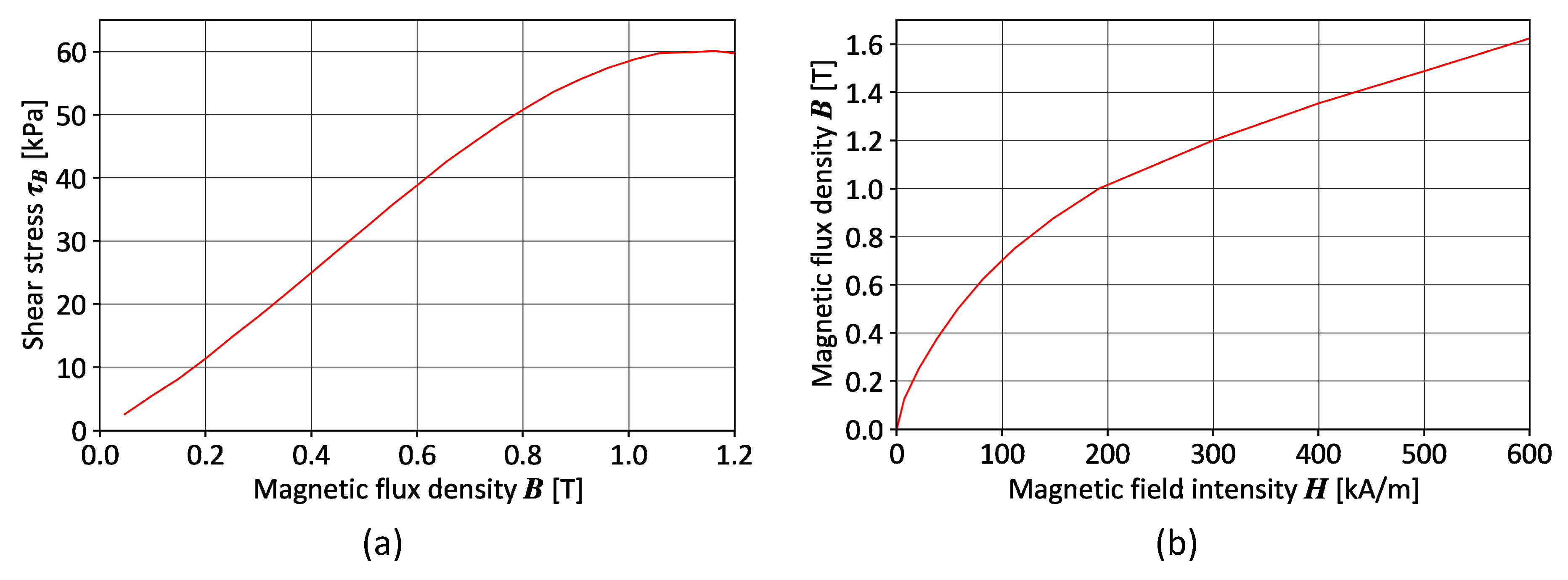
2.3. MRF Used in Simulations

To carry out the study, it was necessary to implement the properties of the MR fluid in the developed FEM model. The authors chose LORD MRF-140CG fluid [45] due to their experience in research and design of MRF-based devices [43,44,46]. The nonlinear relationship of shear stress and magnetic flux density for MRF-140CG based on data from [47] is shown in Figure 7a, while nonlinear magnetic properties of the selected MRF have been described by the BH curve [45] shown in Figure 7b.

2.4. Conditions under Consideration

The stresses in MRF were analyzed along the length of the segment indicated by r in red in Figure 8 in three cases. For Instance 1, the section of the undeformed cushion is 2 mm from the bottom of the cushion. For Instance 2, the section of the deformed cushion is 2 mm from the bottom of the cushion. For Instance 3, the section of the deformed cushion is 6.4 mm from the bottom of the cushion. It should be noted that r = 0 determines the symmetry axis of the MR cushion and the entire permanent magnet and yoke setup. Stress analysis was performed at different distances from the magnetic field exciter to the bottom of the MR cushion (Figure 5 and Figure 8). The value z = 0 defines the situation in which the front of the permanent magnet rests against the base of the MR cushion. The purpose of the study was to determine the distribution of shear stress within the MR cushion for different configurations of the magnetic field source system geometry and the distance z of the exciter from the cushion.

3. Results

3.1. Influence of Magnet Thickness gm

Figure 9 shows the average values of stresses occurring in the cross section of the cushion at a height of 2 mm from its base for different values of gm. The first observation is that the value of shear stresses increases with an increase in the gm dimension. It determines the geometry of the permanent magnet and, therefore, the source of the magnetic field. In doing so, it is important to note the differences between smaller gm values, such as 2, 3, and 4 mm, which bring a significant change to the setup performance. For larger values, such as 6, 7, and 8 mm, the changes are smaller and mainly include an increase in average shear stress values for configurations with kpm equal to 0.9. The highest value of the mean shear stress for gm = 6 mm was achieved with a configuration of kpm = 0.8 and kj = 0.65; for gm = 7 mm; it was kpm = 0.8 and kj = 0.6, while for gm = 8 mm; the configuration was kpm = 0.8 and kj = 0.6.

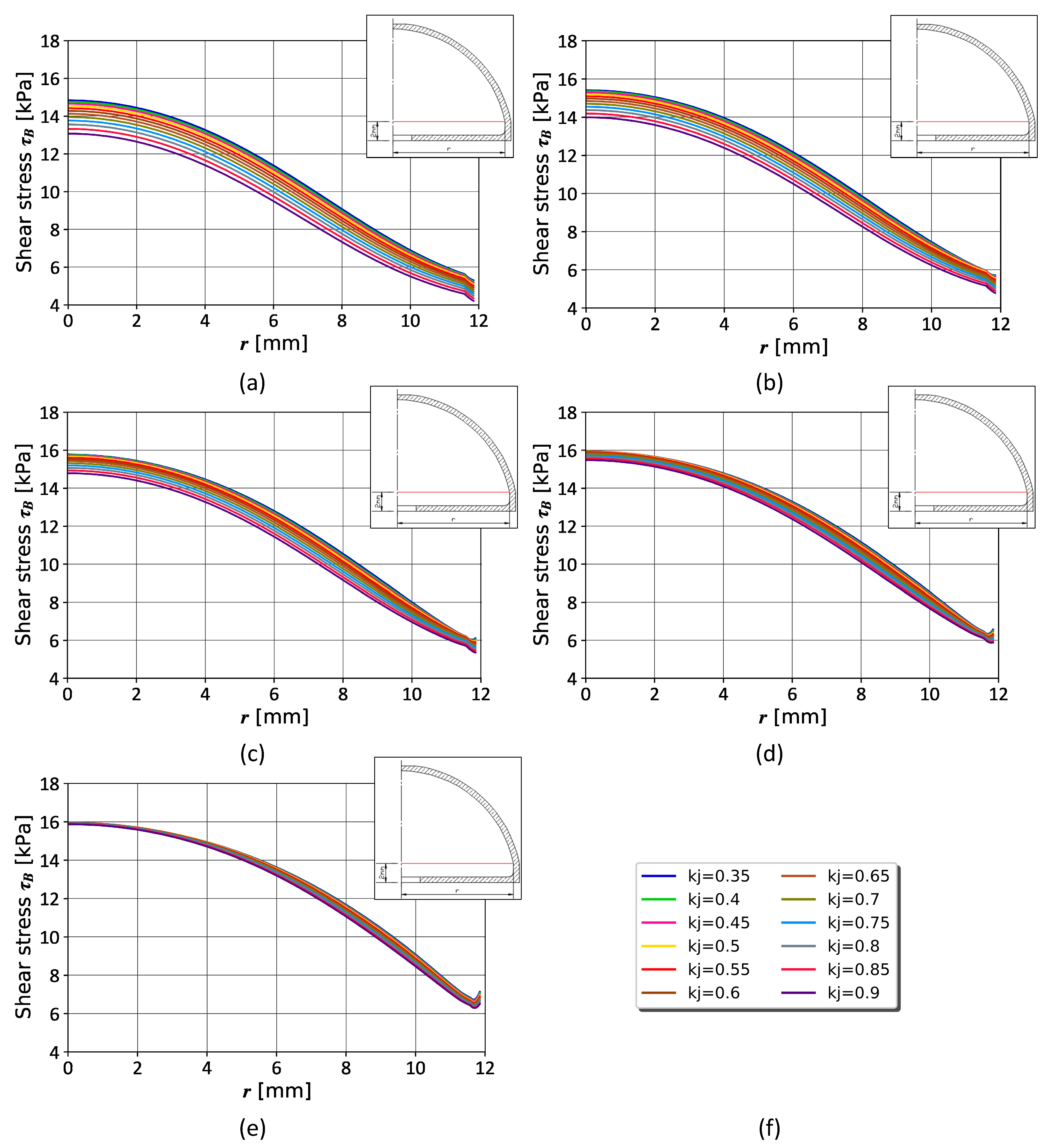
3.2. Analysis of Parameters kpm and kj

The initial assumption is that higher shear stresses are expected to be obtained for higher values of kpm and gm. These affect the geometry of the permanent magnet. As studies discussed in the framework of this article have shown, the air gap and yoke geometry also have a significant impact on the distribution of the shear stress in MRF. Stress distributions along the length of the section r at a height of 2 mm from the bottom of the cushion are shown in Figure 10, Figure 11 and Figure 12. Analyzing the configurations for z = 1 (Figure 10), it is clear that there is a simple relationship between increased stress and a decrease in the kj factor for kpm = 0.7 (Figure 10a). On the other hand, an increase in the value of the kj coefficient for configurations with kpm equal to 0.85 and 0.9 results in an increase in stress values along the entire length of the cushion cross section (Figure 10d,e). Configurations with kpm equal to 0.75 and 0.8 seem to integrate both trends discussed. For kpm = 0.75 and a factor kj with values up to 0.6, it increases the stresses acting as configurations with kpm of 0.85 and 0.9. After that, it reduces the stress values for the extreme points farthest from the cushion axis of symmetry (r > 6), thus exhibiting the configurations with kpm = 0.7. With kpm = 0.8 and a factor kj with values up to 0.6, it increases stress values behaving like configurations with kpm of 0.85 and 0.9. Then, it maintains the stress level built thereby to kj = 0.8 and reduces the stress values for the extreme points farthest from the cushion’s axis of symmetry (r > 6). Figure 10 shows very well the consequences of higher stress values near the axis of symmetry of the cushion for smaller kpm parameters. Looking at the stress values for r equal to 8 mm (2/3 of the cushion base radius distance), it can be observed that for kpm equal to 0.7 and 0.75 they do not exceed 28 kPa. For kpm of 0.8 and 0.9 the stress values are concentrated around 28 kPa. On the other hand, for kpm equal to 0.85, all kj configurations provide stress values greater than 28 kPa. Thus, it is worth noting the stress values close to the axis of symmetry. For kpm equal to 0.7 and 0.75, they oscillate around 36 kPa; for kpm equal to 0.8 and 0.85, they oscillate below the value of 36 kPa, and for kpm equal to 0.9, they oscillate around 32 kPa. It follows that for magnet thickness gm = 6 mm and distance z = 1 mm, the configuration with kpm = 0.8 and kj = 0.65 presents the most favorable in terms of uniformity of distribution of shear stress values in the cross section of the cushion. In the following section, a similar analysis is described for permanent magnet distances z equal to 5 and 10 mm.
Figure 11 shows, analogously to Figure 10, the stress values for various configurations kpm/kj at gm = 6 mm, this time for distance z = 5 mm. It should be noted that there is a common trend among the different configurations of kpm, suggesting the highest stress values in the configurations kj = 0.35. The conclusion in this case is that the air gap has a positive impact on the magnetic field excitation depth into the cushion. The second observation is the leveling of disproportions between configurations with individual kj with an increase in the value of the kpm coefficient, which shows a reduction in the separation between the characteristics. Similarly, for the analysis for z = 1 mm, it is worth noting the stress values further away from the axis of the symmetry. Looking at the stress values for r equal to 8 mm (2/3 of the distance of the cushion base radius), we can observe that for kpm equal to 0.7, they exceed 9 kPa. For kpm = 0.75, they are in the range of 8–10 kPa; for kpm = 0.8, the range is approximately 9–10.5 kPa. For kpm = 0.85, the range is between 10 and 11 kPa, and for kpm = 0.9, the stress values are greater than 11 kPa. It follows that for magnet thickness gm = 6 mm and permanent magnet face distance z = 5 mm, the configuration with kpm = 0.9 and kj = 0.35 presents the most favorable in terms of uniformity of distribution of shear stress values in the cross section of the cushion. Interestingly, compared to the graphs in Figure 10, this configuration provides the highest values of shear stress on the axis of cross-section symmetry. For illustrative purposes, Figure 12 presents the stress distributions in the cushion section at a distance of z = 10. They demonstrate the impact of the various configurations, and thus the justification of the thesis proposed in the analysis for z = 5.

3.3. Assessment of the Average Stress Distribution

Due to the large range of data, it is difficult to evaluate and compare individual configurations. For this reason, the author’s method of comparing average values on the measurement section r was proposed. This method also allows us to identify configurations with the desired uniform distribution of shear stresses inside the cushion.
The effect of the configuration of the geometry of the magnetic field exciter setup on the distribution of the average shear stress along the measurement section was analyzed. Figure 13 shows the average values of shear stresses occurring along length r for permanent magnet configurations with thickness gm = 6 mm and the distance of the magnetic field source z equal to 0, 1, 5, and 10 mm. For the first case, in which we assume perfect overlap between the permanent magnet face and the cushion base (z = 0, Figure 13a), the highest average shear stress value of 40.69 kPa is observed for kpm = 0.8 and kj = 0.75. On the other hand, as discussed in Section 3.2 and Section 3.3, the lowest value of average shear stress of 34.416 kPa is obtained for configurations kpm = 0.9 and kj = 0.35. The case in Figure 13b (z = 1) represents a situation in which there is a certain air space of 1 mm between the bottom of the MRF cushion and the face of the permanent magnet. The shape of the surface plot does not differ much from that obtained at z = 0. It is worth noting the reduction in shear stress values and the lowering of the hooked apex in the border configuration for kpm = 0.7 and kj = 0.9, confirming the observations in Figure 10a. The highest value of the mean shear stress in this case is 30.49 kPa for kpm = 0.8 and kj = 0.65. Observation of the surface plots for z = 5 (Figure 13c) and z = 10 (Figure 13d) leads to an identical conclusion. Taking into account the goal of obtaining the highest values of shear stress when moving the magnetic field exciter away, the most favourable geometry configuration is to use as large a permanent magnet diameter as possible (large kpm) and as small a yoke width as possible (small kj). However, because of the application of the system in question, it is advantageous to obtain high values of shear stress in close proximity to the magnetic field source and low values when moving away. This will make it possible to obtain the appropriate softness of the cushion when the object appears in its area and adapts to its shape. When the jaws are further, in turn, the insertion of a magnetic field into the volume of the cushion stiffens the structure, providing a more stable grip.
The authors carried out an analogous analysis of the values of average stresses along the length of the measuring section r, also for the case with a plunged pin noted as Instance 2 (Figure 14). Although the shape of the surface plots is the same as in Figure 13, the indications of the shear stress magnitudes are slightly different. Instance 2 tends to achieve slightly lower stress values compared to Instance 1. This difference reduces as the distance z increases.
Analysis of the difference in the average shear stress values for Instances 1 and 2 led the authors to check the distribution of the average stress values at the height of the plunged pin (Instance 3). The results are shown in Figure 15. This area is extremely important from the point of view of the application and the expected effects of inserting a magnetic field into the cushion. The occurrence of high shear stresses promotes a reduction in the ability of the held object to move, due to the hardening of the cushion structure. As can be seen in this area, the highest values of average stresses are achieved for configurations with kpm equal to 0.9, regardless of the distance z. The lowest values, on the other hand, are achieved for kpm = 0.7 and kj = 0.9. A particularly important area are configurations with kpm 0.8 and 0.85, which for a low distance z reach comparable values with kpm = 0.9. In turn, as the distance z increases, they decrease much more.

4. Discussion

As a result of the analysis, four kpm/kj configurations were selected for gm = 6 mm, as shown in Figure 16. The first is a variant with kpm = 0.7 and kj = 0.9 (Figure 16a), where high stress values could be observed near the axis of symmetry. As the distance r increased, there was a significant reduction relative to the other configurations. This resulted in the lowest average shear stress values in both Instances 1 (Figure 13) and 3 (Figure 15) analyzed. The configuration in Figure 16d is a variant with kpm = 0.9 and kj = 0.35, which also represents an edge case. It is worth noting that the distributions for Instance 1 (Figure 13) represent the lowest values of average stresses, so for Instance 3 (Figure 15), they allow the highest values with increasing distance z. The two middle configurations in Figure 16b,c are the favorites of the analysis, characterized by high shear stresses both in the area near the bottom of the cushion and around the plunged object. Moreover, they allow one to achieve the expected effect of high stresses for small values of z and low ones while increasing it.
Figure 17a shows the principle of operation of the spring-permanent magnet mechanism introduced in Section 1 (Figure 2 and Figure 3). Figure 17b shows plots of the magnetic field exciter’s attraction force as a function of the size of the air gap between the cushion (determined by the height z). They are shown for the configurations selected in Figure 16. These data are the culmination of the analysis performed and are helpful in the selection of counter springs for the proposed mechanism. According to Figure 17a, there are two opposite facing forces. The first comes from the springs FS, which react to a change in distance z. This response is linear and depends on the spring deflection. For design reasons, a spring deflection of 8.8 mm was assumed. The second force comes from the attraction of the permanent magnet FM, which increases as the air gap z decreases. It is exponential in nature and for the given configurations reaches values above 25 N. However, it should be borne in mind that there is one plate between the face of the permanent magnet and the MR fluid, and the thickness of its bottom. On the basis of experience with prototypes, this size was taken as 1.8 mm. In order to ensure correct operation at the z-point equal to 0, the two forces must at least align with each other. The minimum difference in favor of springs is necessary to move the cushion away from the permanent magnet while removing the pressure from the jaws (releasing the grasped object). However, it is not recommended to insert hard springs, which will significantly exceed the value of the force at the z-point equal to 0. This is due to the biggest limitation of the proposed solution, which is the force required to plunge the object into the cushion. The higher the reaction force of the springs, the more force must be applied on the jaw side to plunge the object into the cushion and bring it closer to the source of the magnetic field. Thus, this disqualifies the use of the cushion for brittle active grasping of fragile objects. Grasping in this case can only be passive without the involvement of a magnetic field, taking advantage of the soft structure of the cushion.

5. Conclusions

The study analyzed the results of a simulation study of a magnetic setup inserting a magnetic field into a cushion filled with magnetorheological fluid. The measured quantities were the shear stresses occurring in the MRF, considered for different configurations of the dimensions of the permanent magnet, yoke, and air gap. These quantities were defined as factors, and the article discusses their influence on the stress distribution.
After the analysis, the following observations were developed. The factors kpm and gm affect mainly the value of shear stresses in the cushion as the air gap between the exciter increases (increasing the distance z). This is because they determine the most important element of the magnetic field exciter, namely the geometry of the permanent magnet. The highest kpm value of 0.9 allows for the highest values of shear stress to be obtained in the measurement section as the distance z increases. This is true for the axis of rotation of the cushion, as well as for points r away from it, compared to the other configurations. Marginally influential in this case is also the chosen value of kj (Figure 11e and Figure 12c). A levelling-down the disparity between configurations with individual kj is observed as the value of the kpm factor increases. This shows a decrease in the separation between the characteristic waveforms. However, because of the nature of the application, it is expected to obtain a stress as high as possible for small values of distance z, with simultaneously low stresses as this distance increases. This will allow the cushion to become sufficiently soft as the object enters its area and conform to its shape. In turn, when the jaws extend further, the introduction of a magnetic field into the volume of the cushion will allow the structure to stiffen, providing a more stable grip. Therefore, the criterion for selecting the geometry of the setup should be determined by analysis for low values of distance z, such as 0, 1, and 2 mm. The goal is to obtain the highest possible values of shear stress on the entire length of r. For this reason, the following analysis details the average stress value for each configuration. For z = 0 and z = 1, the highest average value was obtained for configurations with kpm = 0.8 and kj = 0.75, and kj = 0.65, respectively. Similar conclusions were also observed when stresses in the air gap region between the permanent magnet and the yoke were analyzed. The analysis of the cushion model with a plunged pin allowed us to show differences in the values of average stresses values, which are higher at small values of z and decrease with the distance of the permanent magnet from the cushion. The authors decided to perform an analysis of the average shear stress at the height of the plunged pin model, which confirmed the previous observations and conclusions. Therefore, in the system application, they recommend configurations with kpm equal to 0.8 and 0.85 and kj oscillating around 0.7.
Summarizing the simulation analysis aspects, one should keep in mind their coverage in real (experimental) conditions. The situations considered include the full filling of the tank with MR fluid, which with the proposed geometry is about 3.2 ml. Thus, the simulation takes into account the same conditions occurring throughout its volume. In practise, the gripper operates at different orientations; therefore, there may be a local accumulation of ferromagnetic particles. This will affect a different distribution of shear stress and magnetic field induction in the volume of the cushion. Another issue is the limitation in the ability to fully fill the tank with MR fluid. Experiments show that partial filling of jamming gripper solutions positively affects the performance of the gripper [15,16,22]. Additionally, such conditions make it difficult to model the actual operating conditions of the proposed solutions.
The suggested approach is characterised by an innovative design considering the proposed solutions presented in the literature review (Section 1). It is featured by the absence of the need to provide a control module, and the gripper itself can operate with the manufacturer’s software. The proposed jaw solution will find its application in the design of almost any jaw gripper. Modernisation itself is not expensive, taking into account the materials and technology used. An important aspect in this case is also the low weight of the device. The original Robotiq 2F-140 gripper jaw weighs approximately 32.2 g, while the proposed one weighs 58.5 g. At the same time, the ∅25 × 20 electromagnet itself weighs about 50 g. This is especially important for small manipulators with a low lifting capacity. Among the disadvantages of the proposed solution will be, in particular, the plate under the cushion, which increases the distance between the magnetic field source and the MR fluid inside the cushion. The low magnetic permeability of the TPU does not help either. Among the challenges is the potential to develop a built-in version to prevent clogging of the mechanism (for example, the appearance of third-party objects between the face of the magnet and the bottom of the cushion). Further analysis is possible for other materials for structural components. The use of MR liquids in this type of gripper solution always carries the risk of leakage during operation. The authors’ further plans include experimental studies of the proposed setup for inserting a magnetic field into an MR fluid-filled cushion and tests on the robotic manipulator.

Author Contributions

Conceptualization, M.B. and C.J.; methodology, M.B. and C.J.; software, C.J.; validation, C.J. and M.B.; formal analysis, C.J. and M.B.; investigation, C.J. and M.B.; resources, C.J. and M.B.; data curation, M.B.; writing—original draft preparation, M.B.; writing—review and editing, C.J.; visualization, M.B.; supervision, C.J.; project administration, M.B.; funding acquisition, M.B. All authors have read and agreed to the published version of the manuscript.

Funding

This research was funded in part by the National Science Centre, Poland grant number: 2021/41/N/ST8/02619 and C.J. was supported by the National Ministry of Science and Higher Education in Poland as a part of research subsidy 0212/SBAD/0568. For the purpose of Open Access, the author has applied a CC-BY public copyright licence to any Author Accepted Manuscript (AAM) version arising from this submission.

Data Availability Statement

The authors are eager to share the results obtained and encourage contact with the corresponding author.

Acknowledgments

M.B. would like to thank Dominik Rybarczyk for supervision of a project 2021/41/N/ST8/02619.

Conflicts of Interest

The authors declare no conflict of interest.

References

  1. Sun, K.; Tian, Y. Numerical investigation of a bioinspired multi-segment soft pneumatic actuator for grasping applications. Mater. Today Commun. 2022, 31, 103449. [Google Scholar] [CrossRef]
  2. Zhu, Y.; Chu, K.; Chen, X.; Wang, X.; Su, H. Research and application of a multi-degree-of-freedom soft actuator. Sens. Actuators A Phys. 2022, 338, 113492. [Google Scholar] [CrossRef]
  3. Lee, D.; Jahanbin, R.; Rahman, S. Robust design optimization by spline dimensional decomposition. Probab. Eng. Mech. 2022, 68, 103218. [Google Scholar] [CrossRef]
  4. Yu, Q.; Jiang, M.; Gravish, N. Flexoskeleton Fingers: 3D Printed Reconfigurable Ridges Enabling Multi-Functional and Low-Cost Underactuated Grasping. IEEE Robot. Autom. Lett. 2021, 6, 3971–3978. [Google Scholar] [CrossRef]
  5. Terrile, S.; Argüelles, M.; Barrientos, A. Comparison of Different Technologies for Soft Robotics Grippers. Sensors 2021, 21, 3253. [Google Scholar] [CrossRef] [PubMed]
  6. Hughes, J.; Culha, U.; Giardina, F.; Guenther, F.; Rosendo, A.; Iida, F. Soft Manipulators and Grippers: A Review. Front. Robot. AI 2016, 3, 69. [Google Scholar] [CrossRef] [Green Version]
  7. Liu, Z.; Zhang, Z.; Liu, W.; Huang, G.; Jiang, Y.; Chen, D. Configuration Design and Verification of Soft-Rigid Hybrid Hand with Ab/Adduction Movement. In Advances in Mechanical Design; Springer: Singapore, 2021. [Google Scholar]
  8. Choi, H.; Koç, M. Design and feasibility tests of a flexible gripper based on inflatable rubber pockets. Int. J. Mach. Tools Manuf. 2006, 46, 1350–1361. [Google Scholar] [CrossRef]
  9. Maruyama, R.; Watanabe, T.; Uchida, M. Delicate Grasping by Robotic Gripper with Incompressible Fluid-Based Deformable Fingertips. In Proceedings of the 2013 IEEE/RSJ International Conference on Intelligent Robots and Systems, Tokyo, Japan, 3–7 November 2013; pp. 5469–5474. [Google Scholar]
  10. Nishimura, T.; Suzuki, Y.; Tsuji, T.; Watanabe, T. Fluid Pressure Monitoring-Based Strategy for Delicate Grasping of Fragile Objects by A Robotic Hand with Fluid Fingertips. Sensors 2019, 19, 782. [Google Scholar] [CrossRef] [PubMed] [Green Version]
  11. Nishida, T.; Shigehisa, D.; Kawashima, N.; Tadakuma, K. Development of Universal Jamming Gripper with a Force Feedback Mechanism. In Proceedings of the 2014 Joint 7th International Conference on Soft Computing and Intelligent Systems (SCIS) and 15th International Symposium on Advanced Intelligent Systems (ISIS), Kitakyushu, Japan, 3–6 December 2014; pp. 242–246. [Google Scholar]
  12. Amend, J.R.; Brown, E.; Rodenberg, N.; Jaeger, H.M.; Lipson, H. A Positive Pressure Universal Gripper Based on the Jamming of Granular Material. IEEE Trans. Robot. 2012, 28, 341–350. [Google Scholar] [CrossRef]
  13. Cramer, J.; Cramer, M.; Demeester, E.; Kellens, K. Exploring the potential of magnetorheology in robotic grippers. Procedia CIRP 2018, 76, 127–132. [Google Scholar] [CrossRef]
  14. Pettersson, A.; Davis, S.; Gray, J.; Dodd, T.; Ohlsson, T. Design of a magnetorheological robot gripper for handling of delicate food products with varying shapes. J. Food Eng. 2010, 98, 332–338. [Google Scholar] [CrossRef]
  15. Choi, Y.T.; Hartzell, C.; Leps, T.; Wereley, N.M. Gripping characteristics of an electromagnetically activated magnetorheological fluid-based gripper. AIP Adv. 2018, 8, 056701. [Google Scholar] [CrossRef] [Green Version]
  16. Nishida, T.; Okatani, Y.; Tadakuma, K. Development of Universal Robot Gripper Using MRα Fluid. Int. J. Hum. Robot. 2016, 13, 1650017. [Google Scholar] [CrossRef]
  17. Tsugami, Y.; Barbie, T.; Tadakuma, K.; Nishida, T. Development of universal parallel gripper using reformed magnetorheological fluid. In Proceedings of the 11th Asian control conference (ASCC) IEEE, Gold Coast, QLD, Australia, 17–20 December 2017; pp. 778–783. [Google Scholar] [CrossRef]
  18. Cramer, J.; Cramer, M.; Demeester, E.; Kellens, K. Simulation-driven parameter study of concentric Halbach cylinders for magnetorheological robotic grasping. J. Magn. Magn. Mater. 2022, 546, 168637. [Google Scholar] [CrossRef]
  19. Naimzad, A.; Ghodsi, M.; Hojjat, Y.; Maddah, A. MREs Development and Its Application on Miniature Gripper. In Proceedings of the 2011 International Conference on Advanced Materials Engineering, Cairo, Egypt, 1–3 October 2011. [Google Scholar]
  20. Skfivan, V.; Sodomka, O.; Mach, F. Magnetically Guided Soft Robotic Grippers. In Proceedings of the 2019 2nd IEEE International Conference on Soft Robotics (RoboSoft), Seoul, South Korea, 14–18 April 2019; pp. 126–130. [Google Scholar]
  21. Balak, R.; Mazumdar, Y.C. Bistable Valves for MR Fluid-Based Soft Robotic Actuation Systems. IEEE Robot. Autom. Lett. 2021, 6, 8285–8292. [Google Scholar] [CrossRef]
  22. Hartzell, C.M.; Choi, Y.-T.; Wereley, N.M.; Leps, T.J. Performance of a magnetorheological fluid-based robotic end effector. Smart Mater. Struct. 2019, 28, 035030. [Google Scholar] [CrossRef]
  23. Widodo, P.J.; Budiana, E.P.; Ubaidillah, U.; Imaduddin, F. Magnetically-Induced Pressure Generation in Magnetorheological Fluids under the Influence of Magnetic Fields. Appl. Sci. 2021, 11, 9807. [Google Scholar] [CrossRef]
  24. Özsoy, K.; Usal, M.R. A mathematical model for the magnetorheological materials and magneto reheological devices. Eng. Sci. Technol. Int. J. 2018, 21, 1143–1151. [Google Scholar] [CrossRef]
  25. Salloom, M.Y.; Samad, Z. Finite element modeling and simulation of proposed design magneto-rheological valve. Int. J. Adv. Manuf. Technol. 2011, 54, 421–429. [Google Scholar] [CrossRef]
  26. Ma, L.; Yu, L.; Song, J.; Xuan, W.; Liu, X. Design, Testing and Analysis of a Novel Multiple-Disc Magnetorheological Braking Applied in Vehicles. In Proceedings of the SAE 2015 World Congress & Exhibition, Detroit, MI, USA, 21–23 April 2015. [Google Scholar] [CrossRef]
  27. Ismail, I.; Mazlan, S.A.; Olabi, A.G. Magnetic Circuit Simulation for Magnetorheological (MR) Fluids Testing Rig in Squeeze Mode. Adv. Mater. Res. 2010, 123–125, 991–994. [Google Scholar] [CrossRef]
  28. Coon, A.; Yang, T.-H.; Kim, Y.-M.; Kang, H.; Koo, J.-H. Application of Magneto-Rheological Fluids for Investigating the Effect of Skin Properties on Arterial Tonometry Measurements. Front. Mater. 2019, 6, 45. [Google Scholar] [CrossRef]
  29. Guo, C.-W.; Chen, F.; Meng, Q.-R.; Dong, Z.-X. Yield shear stress model of magnetorheological fluids based on exponential distribution. J. Magn. Magn. Mater. 2014, 360, 174–177. [Google Scholar] [CrossRef]
  30. Shintake, J.; Cacucciolo, V.; Floreano, D.; Shea, H. Soft Robotic Grippers. Adv. Mater. 2018, 30, 1707035. [Google Scholar] [CrossRef] [PubMed] [Green Version]
  31. Lanzetta, M.; Iagnemma, K. Gripping by controllable wet adhesion using a magnetorheological fluid. CIRP Ann. 2013, 62, 21–25. [Google Scholar] [CrossRef]
  32. Koivikko, A.; Drotlef, D.-M.; Sitti, M.; Sariola, V. Magnetically switchable soft suction grippers. Extreme Mech. Lett. 2021, 44, 101263. [Google Scholar] [CrossRef] [PubMed]
  33. Zhang, M.; Chen, X.; Sun, Y.; Gan, M.; Liu, M.; Tang, S.-Y.; Zhang, S.; Li, X.; Li, W.; Sun, L. A Magnetically and Thermally Controlled Liquid Metal Variable Stiffness Material. Adv. Eng. Mater. 2022, 2201296. [Google Scholar] [CrossRef]
  34. Zhou, X.; Shu, J.; Jin, H.; Ren, H.; Ma, G.; Gong, N.; Ge, D.-A.; Shi, J.; Tang, S.-Y.; Yun, G.; et al. Variable stiffness wires based on magnetorheological liquid metals. Int. J. Smart Nano Mater. 2022, 13, 232–243. [Google Scholar] [CrossRef]
  35. Cassar, D.J.; Saliba, M.A. A Force Feedback Glove Based on Magnetorheological Fluid: Preliminary Design Issues. In Proceedings of the Melecon 2010–2010 15th IEEE Mediterranean Electrotechnical Conference, Valletta, Malta, 26–28 April 2010; pp. 618–623. [Google Scholar]
  36. Nguyen, Q.H.; Choi, S.; Lee, Y.S.; Han, M.S. Optimal design of a new 3D haptic gripper for telemanipulation, featuring magnetorheological fluid brakes. Smart Mater. Struct. 2013, 22, 015009. [Google Scholar] [CrossRef]
  37. Liu, Q.; Jing, T.; Mo, A.; Xu, X.; Zhang, W. A Novel Robot Hand with the Magneto-Rheological Fluid Solidification. In Proceedings of the 2015 IEEE International Conference on Robotics and Biomimetics (ROBIO), Zhuhai, China, 6–9 December 2015; pp. 2495–2500. [Google Scholar]
  38. Shembekar, S.; Kamezaki, M.; Zhang, P.; He, Z.; Tsunoda, R.; Sakamoto, H.; Sugano, S. Preliminary Development of a Powerful and Backdrivable Robot Gripper Using Magnetorheological Fluid. In Proceedings of the 2020 Proceedings of the 37th ISARC, Kitakyushu, Japan, 27–28 October 2020; pp. 1458–1463. [Google Scholar] [CrossRef]
  39. Pisetskiy, S.; Kermani, M.R. A Concept of a Miniaturized MR Clutch Utilizing MR Fluid in Squeeze Mode. In Proceedings of the 2020 IEEE/RSJ International Conference on Intelligent Robots and Systems (IROS), Las Vegas, NV, USA, 24 October 2020–24 January 2021; pp. 6347–6352. [Google Scholar]
  40. Fernandez, M.A.; Chang, J.-Y. Design of an Adjustable Fail-Safe MRF Clutch with a Novel Field Blocking Mechanism for Robotic Applications. IEEE Access 2021, 9, 164912–164927. [Google Scholar] [CrossRef]
  41. Weiss, K.D.; Duclos, G.T.; Chrzan, M.J.; Yanyo, L.C. Magnetorheological Fluid Composite Structures. U.S. Patent US005547049A, 20 August 1996. [Google Scholar]
  42. Ghaffari, A.; Hashemabadi, S.H.; Ashtiani, M. A review on the simulation and modeling of magnetorheological fluids. J. Intell. Mater. Syst. Struct. 2015, 26, 881–904. [Google Scholar] [CrossRef]
  43. Białek, M.; Jędryczka, C.; Milecki, A. Investigation of Thermoplastic Polyurethane Finger Cushion with Magnetorheological Fluid for Soft-Rigid Gripper. Energies 2021, 14, 6541. [Google Scholar] [CrossRef]
  44. Białek, M.; Rybarczyk, D. A Comparative Study of Different Fingertips on the Object Pulling Forces in Robotic Gripper Jaws. Appl. Sci. 2023, 13, 1247. [Google Scholar] [CrossRef]
  45. LORD Company MRF-140CG documentation. Available online: https://lordfulfillment.com/pdf/44/DS7012_MRF-140CGMRFluid.pdf (accessed on 28 November 2022).
  46. Jędryczka, C. FE analysis of electromagnetic field coupled with fluid dynamics in an MR clutch. COMPEL-Int. J. Comput. Math. Electr. Electron. Eng. 2007, 26, 1028–1036. [Google Scholar] [CrossRef]
  47. Pilch, Z.; Domin, J. Conception of the throttle-return valve for the magnetorheological fluid. Arch. Electr. Eng. 2018, 67, 37–49. [Google Scholar] [CrossRef]
Figure 1. Classification of grippers using MRF, based on [6]. The grey rectangle indicates the area covered by the article. The Grippers’ images are from the following publications [6,14,15,16,17,21,22,30,31,32,33,34,35,36,37,38,39,40,41].
Energies 16 02299 g001
Figure 2. Research object, i.e., Robotiq 2F-140 gripper equipped with the cross section of a custom MRF cushion fingerpad.
Energies 16 02299 g002
Figure 3. The principle of operation of the proposed magnetic spring solution in cross-sectional view of the jaw.
Energies 16 02299 g003
Figure 4. Simulation environment: (a) exemplary FE mesh; (b) magnetic flux and magnetic flux density plots; (c) determined stress distribution in MRF.
Energies 16 02299 g004
Figure 5. Graphical explanation of the geometry factors of the analyzed configuration and the cushion. Defined factors dpm, wr, wj, and distances z from the magnetic field exciter to the base of the cushion.
Energies 16 02299 g005
Figure 6. Supplement of Figure 5 with dimensions of dpm and wj depending on the kj/kpm configuration.
Energies 16 02299 g006
Figure 7. Information about MRF and stress analysis within the article: (a) shear stress τB versus magnetic flux density B curve [47]; (b) magnetic flux density B versus magnetic field intensity H for MRF-140CG [45].
Energies 16 02299 g007
Figure 8. The configuration matrix of optimisation study setups including kj, kpm, gm geometry parameters, and z-distance scenarios. Three instances were studied.
Energies 16 02299 g008
Figure 9. Average τB shear stress distributions for Instance 1 with z = 1 and gm equal to: (a) 2 mm; (b) 3 mm; (c) 4 mm; (d) 5 mm; (e) 6 mm; (f) 7 mm; (g) 8 mm; (h) color scale indicating shear stress value.
Energies 16 02299 g009
Figure 10. Shear stress distribution τB for Instance 1—distance z = 1 mm and thickness gm = 6 mm with different configurations of the kj factor for kpm equal to: (a) 0.7; (b) 0.75; (c) 0.8; (d) 0.85; (e) 0.9; (f) legend.
Energies 16 02299 g010
Figure 11. Shear stress τB distribution for Instance 1—distance z = 5 mm and thickness gm = 6 mm using different configurations of the kj factor for kpm equal to: (a) 0.7; (b) 0.75; (c) 0.8; (d) 0.85; (e) 0.9; (f) legend.
Energies 16 02299 g011
Figure 12. Shear stress τB distribution for Instance 1 distance z = 10 mm and thickness gm = 6 mm using different configurations of the kj coefficient for kpm equal to: (a) 0.7; (b) 0.8; (c) 0.9; (d) legend.
Energies 16 02299 g012
Figure 13. Average values of shear stress τB along the measurement section of the MR cushion cross section (Instance 1) for all configurations kpm/kj. Analysis was performed for the value gm = 6 mm and the magnetic field exciter distance z equal to: (a) 0 mm; (b) 1 mm; (c) 5 mm; (d) 10 mm; (e) color scale indicating shear stress value.
Energies 16 02299 g013
Figure 14. Average values of shear stress τB along the measurement section of the MR cushion cross section (Instance 2) for all configurations kpm/kj. Analysis was performed for the value gm = 6 mm and the magnetic field exciter distance z equal to: (a) 0; (b); (c) 5; (d) 10 mm; (e) color scale indicating shear stress value.
Energies 16 02299 g014
Figure 15. Average values of τB shear stress along the measurement section of the MR cushion section of the Instance 3 variant for all configurations kpm/kj. Analysis was performed for the value gm = 6 mm and the distance of the magnetic field exciter z equal to: (a) 0; (b) 1; (c) 5; (d) 10 mm; (e) color scale indicating shear stress value.
Energies 16 02299 g015
Figure 16. Shear stress distribution in the cushion cross section at gm = 6 mm for configurations: (a) kpm = 0.7 and kj = 0.35; (b) kpm = 0.8 and kj = 0.7; (c) kpm = 0.85 and kj = 0.65; (d) kpm = 0.9 and kj = 0.35; (e) color scale indicating shear stress value.
Energies 16 02299 g016
Figure 17. The value of the attraction force of the exciter as a function of the change in the distance of the magnetic field source z for selected geometry configurations in conjunction with spring reaction: (a) graphical explanation; (b) chart.
Energies 16 02299 g017
Disclaimer/Publisher’s Note: The statements, opinions and data contained in all publications are solely those of the individual author(s) and contributor(s) and not of MDPI and/or the editor(s). MDPI and/or the editor(s) disclaim responsibility for any injury to people or property resulting from any ideas, methods, instructions or products referred to in the content.

