Abstract
Recently, controlling a wind energy conversion system (WECS) under fluctuating wind speed and enhancing the quality of power delivered to the grid has been a demanding challenge for many researchers. This paper provides a comprehensive review of synchronous generator-based WECSs. This paper will investigate the growth of wind energy in Egypt and throughout the world, as well as the technological and financial significance of wind energy. The block diagram of a typical grid-connected WECS, power control techniques, characteristic power curve-based maximum power point tracking (MPPT), and MPPT techniques are also presented in this study. Moreover, this study compares different power converter topologies for grid-connected and independent WECSs that use a permanent magnet synchronous generator (PMSG).
1. Introduction
Before the emergence of industrial society, societies fulfilled their energy demands mostly via the utilization of human and animal effort with some aid from wood burning for cooking, heating, and metal smelting. The industrial revolution was powered by the discovery of plentiful coal and the corresponding technological advancements in its usage. Steam engines, automated manufacturing, and better transportation all run entirely on coal. The discovery and consumption of oil increased throughout the interwar period. During the Second World War, obtaining access to this essential fuel became a major concern. Oil had a significant role in post-World War II economic expansion and prosperity, as well as a significant rise in the usage of private automobiles. During the Second World War, obtaining access to this essential fuel became a major concern. Oil was a major factor in both the large increase in private automobile use and post-World War II economic expansion. Recently, natural gas has played a major role in supporting a new era of economic expansion [1,2,3,4].
Since more than a century ago, electricity has been widely available, and a large portion of it is produced using coal and gas. Because of its adaptability and simplicity of delivery, electricity is a premium kind of energy. Global demand is rising because of rising consumer electronics, associated industrial activities, and greater consumer access in emerging nations. The most reliable and progressive renewable energy source in recent decades is wind power [1,2,3,4]. Utilizing the highest amount of wind power available and operating the wind turbine (WT) at its maximum energy conversion output is essential for the rapid adoption of wind generators in electrical grids. To complete this, a wind energy conversion system (WECS) must track or run at the maximum power point. A significant number of publications have studied different maximum power point tracking (MPPT) techniques for a WECS [5,6,7,8]. The authors of [5] presented a straightforward control technique for optimum output power extraction from grid-connected variable speed WECSs. The system consists of a diode bridge rectifier, a DC-to-DC boost converter, a current-regulated voltage source inverter, a variable speed wind turbine, and a permanent magnet synchronous generator (PMSG). MATLAB-Simulink software (MathWorks (Natick, MA, United States)) was used to model the PWM controllers for the DC–DC and DC–AC converters as well as the MPPT step and search algorithms. The developed simulation results verified that the goals of capturing the largest amount of wind energy and properly distributing it to the grid are accomplished. The authors of [6] proposed a Simulink model of the wind generation system and discussed the key models of the system’s components. To simulate a stand-alone wind power generating system, the model of a wind turbine was coupled with a PMSG. The suggested model was simulated, whereas the rectified output voltage of the PMSG was connected to a battery and a load through a DC–DC buck converter. The obtained results indicated that the output power of the standalone wind system varied with wind speed. This model was modified further so that it can be used for the analysis and modeling of hybrid or grid-connected wind systems [7]. A PMSG based on a WT and connected to the grid through back-to-back converters was modeled as a tiny signal. Two MPPT controllers were included in the suggested small signal model: tip speed ratio (TSR) control and optimal torque control (OTC). To demonstrate the capabilities of MPPT and power smoothing, these approaches were analytically compared. Then, simulations were performed in the MATLAB/Simulink program to compare the MPPT and the power smoothing operation of the aforementioned approaches. According to the simulation results, TSR control has unquestionably quick responses to changes in wind speed at the expense of higher fluctuations because of its nonminimum phase characteristic, whereas OTC is highly effective in power smoothing enhancement and has good performance to extract the maximum power from wind [8]. Concerning a WECS built on a PMSG, the authors have employed the classical, P and O, and PSF approaches. They have determined the electrical and mechanical characteristics of the turbine and the PMSG to acquire the WECS’s actual behavior [9]. The behavior of each optimization approach has been highlighted through a comparison of several optimization techniques. Better stability is presented by P and O and PSF techniques with a tolerable overshoot. Combining the PSF approach with the traditional one to improve performance will be fascinating. However, selecting the precise MPPT method for a given instance requires significant expertise because each technique has advantages and disadvantages of its own. This makes a proper examination of those techniques imperative. Furthermore, the benefits, drawbacks, and comprehensive comparisons of the various MPPT techniques [9] are highlighted. Wind energy, the most frequently utilized renewable energy source, has continued to play an important role. However, the efficiency and cost-effectiveness of a WT system in terms of wind application are highly dependent on its control. Wind energy control techniques have lately been created. Although, there has been an attempt to examine various control strategies [10]. In [10], the authors have placed more of their attention on techniques that use MPPT for wind turbine systems to significantly increase efficiency and energy extraction. One of the common MPPT techniques is the method through the typical power curve. Without the need for real-time wind speed data, the reference current can be calculated using the power-current relationship [11]. These MPPT algorithms can be broadly divided into main control methods, including the optimal torque control (OTC), power signal feedback control (PSF), tip speed ratio control (TSR), hill climb search control (HCS), perturb and observation control (P and O), and incremental conductance control (INC) control [12].
In the fields of renewable energy research, wind energy conversion technologies are gaining popularity. The squirrel cage induction generator (SCIG), doubly fed induction generator (DFIG), wound field synchronous generator (WFSG), and permanent magnet synchronous generator (PMSG) are the most often utilized generators with WECSs. Table 1 shows a comparison of different types of wind turbines [13,14]. PMSG is becoming more and more popular lately because it offers numerous advantages over traditional generators. Since wind is unpredictable, PMSG cannot be connected to the grid directly. The generator and the grid must be connected through an intermediate power electronic link. PMSG uses a variety of power electronic converter topologies [15].

Table 1.
Wind Turbine System Comparison [13,14,15].
This paper provides a comprehensive study of synchronous generator-based WECSs. This paper will investigate the wind energy equation, classification of wind turbine rotors, features of horizontal axis wind turbines (HAWTs) and vertical axis wind turbines (VAWTs), the world wind energy scenario, and the history of wind energy production in Egypt and throughout the world in addition to its technoeconomic relevance. Furthermore, the block diagram of a typical grid-connected WECS is discussed. Moreover, the different power control techniques in wind turbines, such as stall control, pitch control, and summary of passive, active, and pitch control of WTs, will be introduced. Moreover, the classification of different MPPT techniques, such as optimal torque control (OTC), power signal feedback (PSF), tip speed ratio (TSR), hill climb search (HCS), perturbation and observation (P and O), incremental conductance (INC), and a summary of MPPT control techniques will be discussed and compared in this study. Finally, different power converters, such as grid-side converters, standalone converters, such as thyristor grid-side converters, hard switched grid-side converters, matrix converters, multilevel converters, and Z-source inverters, will be comprehensively discussed.
2. Wind Energy
Wind energy is one of the fastest-growing approaches to producing electrical power in the world. Wind power or wind energy is the process of using the wind to produce mechanical or electrical power. Wind energy has been utilized for at least 3000 years [16,17]. Up to the 20th century, wind energy was employed to generate mechanical power for tasks such as water pumping or grinding grain applications [16,17]. At the outset of modern industrialization, the use of erratic wind energy supply has been superseded using fossil fuel-fired engines or electrical grids, which are considered a reliable power source. Therefore, the usage of wind energy is separated into two categories: (1) the generation of mechanical power and (2) the generation of electrical power.
Wind is simple air in motion, and it is caused by the uneven heating of the earth’s surface by the sun. The sun’s heat is absorbed by the earth’s surface at varying rates since the land and water types are so diverse. The air above land warms up during the daytime quicker than the air above the sea. The heavier and cooler air rushes in to replace the expanding and rising warm air over the ground, causing winds. Because the air cools quicker over land than it does over water at night, the winds are inverted. Similar to how the area around the equator is scorched by the sun more than the land near the North and South Poles, the huge air winds that circle the world are generated. Today, electricity is primarily produced via wind energy. Since wind will continue to blow if the sun is shining, wind is referred to as a renewable energy source [16,17].
2.1. Wind Energy Equation
Environmental conditions can influence the available wind energy in a location. However, wind turbine design aspects also play a key role in the energy capacity of the turbine. The amount of energy produced by a turbine is given as follows [18]:
Environmental conditions, such as air density, , and wind velocity, U, are uncontrollable parameters of nature. Air density changes with elevation, temperature, and humidity. The speed, direction, and intensity of the wind are functions of the site location [19]. Design parameters such as the swept area, A, and coefficient of performance,, influence the energy capacity of the turbine and can be maximized with proper design [20].
2.2. Classification of Wind Turbine Rotors
According to how the axis of rotation faces the direction of the wind, wind turbines are often divided into two groups [21,22,23,24]:
- Vertical-axis turbines;
- Horizontal-axis turbines.
2.2.1. Vertical-Axis Wind Turbines
The vertical-axis framework served as the foundation for the earliest windmills. Only small-scale installations of this kind have used it. The Darrius rotor, as seen in Figure 1, is a common component of vertical-axis wind turbines (VAWTs) [21,22]. Rotor shafts in VAWTs are placed vertically. It is not necessary for the vertical shaft that the blades revolve around to face the wind to be vertical. The advantage of a vertical axis rotating shaft is that the generator and electrical components may be positioned close to the ground. The blades of a VAWT are subject to turbulence and drag forces. Because it is difficult to put vertical blades on a tall tower, the turbine must be located close to the ground. This causes the turbine to be influenced by sluggish wind and greater turbulence, which causes vibration and requires more maintenance [23,24].
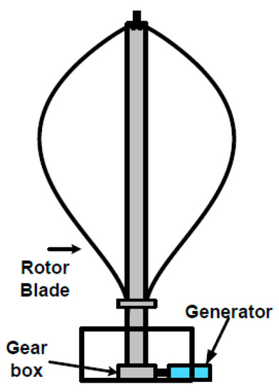
Figure 1.
A typical vertical-axis turbine (the Darrius rotor).
2.2.2. Horizontal-Axis Wind Turbines
The most widespread form of a wind turbine is horizontal axis wind turbine (HAWT). The structure of a HAWT is modeled after windmills, which feature blades that revolve and spin along a horizontal axis, as seen in Figure 2 [21,22]. The rotor shaft, which is regarded as the shaft of the electrical generator, is primarily the horizontal axis. When the wind turbine is modest in size. The horizontal shaft is linked to the generator shaft directly; however, when the wind turbine is large, it is connected via a gearbox. The gearbox serves to improve the speed while reducing stress and vibration. It is situated between moderate and fast rotational speeds. VAWTs can face upwind or face downwind [23,24]. Since mounting and pointing the blades upwind would reduce the turbulence impact created by the tower, upwind turbines must be constructed with robust blades to resist bending by high winds toward the tower [23]. The blades may be constructed with less stiffness in downwind turbines because they have more room to bend and will not bend toward the tower, which solves the problem of turbulence created by the tower. Most wind turbines are constructed upwind because turbulence stresses the blades and produces fatigue problems [23,24]. Table 2 shows the features of HAWTs and VAWTs [25,26].
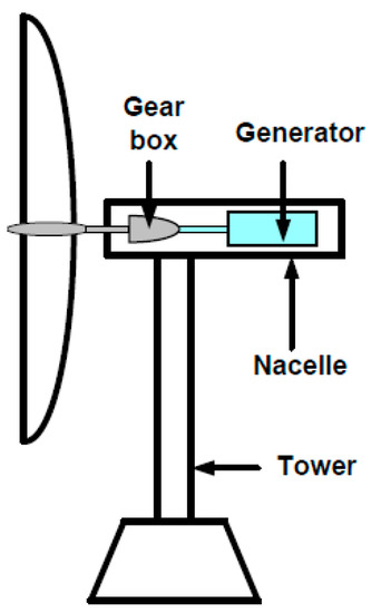
Figure 2.
A horizontal-axis wind turbine.
Table 2.
Features of HAWTs and VAWTs [25,26,27].
2.3. World Wind Energy Scenario
According to records from the Global Wind Energy Council (GWEC), installed wind power increased globally in 2021 to 837 GW, preventing the emission of more than 1.2 billion tons of CO2 annually. With 93.6 GW of the new installed capacity, 2021 is now the second-best year in the history of growth for the global wind industry, trailing only the record-breaking year of 2020, which was 1.8% higher. The top producers globally are China, the United States of America, Germany, India, and Spain [28]. The global wind power output for the last ten years in 2021 is shown in Figure 3a. Figure 3b shows the wind energy output for the top five countries in the globe in 2021. With 328,973 GW, China produces the most wind energy worldwide. With 132,738 GW, the United States ranks in second place in the world and first place in North America for wind energy. With 63,776 GW, Germany has the biggest capacity in Europe. Figure 3c shows the top five African countries in terms of wind energy production in 2021. With 2956 MW, South Africa has the most wind power generation in Africa. Morocco comes in third place with a production of around 1435 MW, while Egypt is in second place with over 1640 MW. In Egypt, the production of electrical power from wind energy began in 2011 with 550 MW and expanded progressively, as seen in Figure 3d, to reach 1640 MW in 2021 [29]. The GWEC anticipates a sharp increase in new installations through 2026 (+6.6%/year), with annual onshore wind installations rising from 72.5 GW in 2021 to 97.4 GW in 2026. Annual offshore wind capacity additions should also pick up from 21.1 GW in 2021 to 31.4 GW in 2026. In total, wind capacity additions should surpass 100 GW/year as of 2022, reaching 128.8 GW in 2026. In terms of capacity increase, China should continue to dominate installations (41% in 2026) followed by Europe (14% in 2026) and North America (7% in 2026) [30].
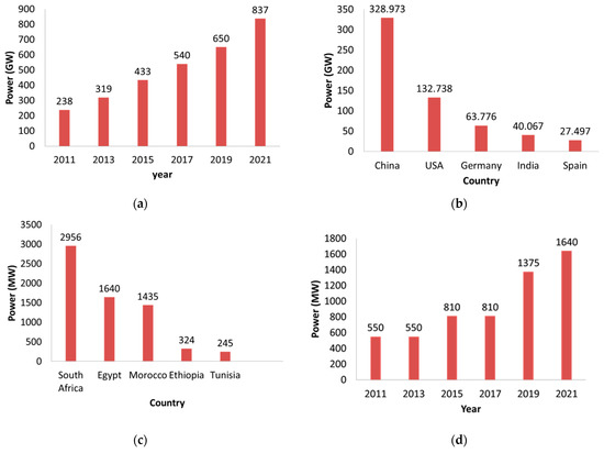
Figure 3.
Wind energy trend in the world and in Africa and Egypt: (a) wind energy trend in the world; (b) top five wind power production in the world in 2021; (c) top five wind power production in Africa in 2021; (d) wind energy trend in Egypt.
3. Block Diagram of a Typical Grid-Connected WECS
In WECSs, a wind turbine and an electric generator are used to produce electrical energy from the wind. The prime mover and the wind turbine can be connected directly or through a gearbox configuration. The rotor of the generator is where the prime mover is connected, and the stator is where the utility grid or separate loads are connected via an appropriate power electronic interface. For the utility grid, this system transforms mechanical energy into magnetic energy and then electrical energy. Figure 4 depicts the block diagram of a typical grid-connected WECS. Depending on their unique operating characteristics at various wind speeds, wind turbines are divided into two groups: variable speed wind turbines (VSWT) and fixed speed wind turbines (FSWT). The generator in FSWTs is directly plugged into the grid. The energy produced by the wind is subject to unpredictable fluctuations until the rotor speed catches up with the grid frequency. The grid’s power quality is significantly impacted by these variations. Power electronics can regulate the generator and rotor speed in VSWT. By adjusting the rotor speed with this control, wind-related power variations can be reduced [31,32,33].
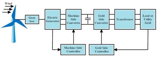
Figure 4.
Block diagram of a typical grid-connected WECS.
4. Power Control Techniques in Wind Turbines
WTs are normally made to tolerate severe weather, but they are not made to handle high rotating speeds or torques. The force acting on the WT’s blades is massive and has the potential to destroy the turbine at very high aerodynamic torques or rotational speeds. WTs are always built with a cut-out speed below which brakes will bring the turbine to a stop and prevent this destruction from happening. The WT uses a variety of control mechanisms to deal with high wind speeds that might otherwise endanger the turbines during a range of wind speeds before the cut-out speed. As a result, all WTs are created with some sort of power control method. Stall control or pitch control are the two options here. Passive and active stall control are additional categories for WT stall management. These control strategies are described in Figure 5 [34,35].
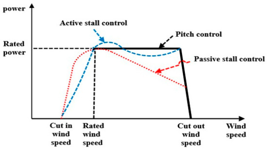
Figure 5.
Power control of WTs.
4.1. Stall Control
The primary benefit of stall control is the avoidance of complicated control systems and moving elements in the rotor itself. On the other side, stall management poses extremely challenging design difficulties in both aerodynamics and the structural dynamics of the entire wind turbine, such as how to prevent stall-induced vibrations. Stall-controlled devices are used in almost two-thirds of the wind turbines that are now installed in the world.
To limit the power in very high wind speeds and prevent wind turbine damage, there are many approaches to managing aerodynamic forces on the turbine’s rotor. As a result, WECSs are divided into three types by the input wind power control ability: passive stall, active stall, and pitch control [36,37,38,39].
4.1.1. Passive Stall Power Control
Blades on passively stalled controlled WTs are fixedly angled when fastened to the hub. To induce turbulence on the side of the rotor blade that is not facing the wind, the geometry of the rotor blade profile is aerodynamically optimized. This stall stops the rotor from being lifted by the rotor blade’s lifting force. When the wind speed approaches its critical value, the rotor blade of a passively stalled controlled WT is gradually twisted along its longitudinal axis to guarantee a progressive stalling rather than a sudden one. This is a straightforward and inexpensive technology that does not need the installation of extra actuators, but since it relies so heavily on the natural stalling of the turbine blades, the controllability of the WT is severely constrained. With passive stall management, as shown in Figure 5, the output power of the WT marginally exceeds the rated limit before falling until it approaches the cut-out speed. By acting in this way, the wind generator is protected from overloading when the wind speed exceeds the nominal values. With no complexity related to WT control or the moving elements of the WT rotor, the passive stall control of WTs offers a relatively straightforward control scheme. Under fixed-speed WT systems, passive stall control is used to ensure that the WT’s rated power is not exceeded in high wind conditions. Because of the limited activities, this usually results in poor power control [37,38,39].
4.1.2. Active stall Power Control
The active stall power control of WTs was devised in reaction to what seemed to be a failure of the passive stall control. Similar to pitch-controlled WTs, active stall-controlled WTs include patchable blades and active power control devices. Although it may also be used with fixed-speed WTs created to operate in high-speed wind situations, active stall management of WTs is common with bigger WTs rated at 1 MW and beyond. The WT blades are pitched in stages when there is little wind to provide a powerful torque. The WT generator must not be overloaded at its rated power; therefore, instead of reducing the angle of attack to decrease the lift and rotational speed of the rotor blades, the active stall-controlled WT increases the angle of attack to cause the blades to enter a deeper stall. Active stall control, as opposed to passive stall control, offers more precise power output management to prevent exceeding the WT’s rated power at the start of a wind gust. Running the WT nearly at rated power at all high wind speeds is another benefit of active stall control over passive stall control. For increasing wind speeds, a passive stall-controlled WT typically experiences a decrease in electrical power production as the rotor blades enter a deeper stall [37,38,39].
4.2. Pitch Control
Pitch-regulated WTs uses an electronic controller to continuously measure the output power of the WT. An electrical signal is generated when the power level exceeds the advised safe limit, which forces the turbine blades to tilt away from the wind. The turbine blades are pitched or turned back toward the wind at the highest angle of attack to collect the wind when the power level declines. By pitching the WT blades, minimal power loss may be accomplished, resulting in the collected power being equivalent to the electrical power generated by the wind generator. To reduce the torque and rotational speed in WTs, pitch-regulated WTs use an active control system that changes the pitch angle of the turbine blades. This type of control is normally employed only when high rotational speeds and aerodynamic torques might destroy the equipment.
Strong wind conditions make the distinctions between the pitch control and stall control of WTs clear. In contrast to stall-controlled systems, pitch-controlled systems actively adjust the pitch of the blades. As a result, the pitch-controlled system can maintain a steady power output above the specified wind speed, but the stall-controlled systems cannot do so in strong winds. WTs’ active stall control and pitch control both depend on the spinning movements of the WT blade. The rotation of the WT blades distinguishes the two modes of operation. In contrast to pitch control, which spins the blade away from the wind to minimize lift force on the turbine blades, active stall control of the WT moves the turbine blades into the wind. Individual pitch control (IPC) and collective pitch control (CPC) are the two control methods used for pitch control of WTs. An electric controller or a hydraulic controller can be used to accomplish either control technique [36,37,38], and a list of the advantages and disadvantages of the stall and pitch control techniques is included in the Table 3 [36,37,38,39].
Table 3.
Summary of passive, active, and pitch control of WTs [36,37,38,39].
5. Characteristic Power Curve-Based MPPT
Most wind energy control systems are based on the monitoring of wind speed. Anemometers are often used in these systems to measure wind speed. Such systems are complicated and have higher sensor costs. Wind speed estimate techniques have been described as a solution to this issue. The wind speed may be measured and used to regulate the ideal tip–speed ratio so that the MPPT can be used. This is conducted by using sophisticated software algorithms. Additionally, directly monitoring the output power might be used to track the maximum power. To obtain the most power out of the wind turbine system, this approach involves measuring the output power in real-time and examining the rate at which power changes with speed, (dP/dω) [40]. By altering the converter’s rotor speed or duty cycle, MPPT may be obtained when dP/dω = 0. Since this approach is heavily reliant on online computing, it would be challenging to accomplish MPPT for rapidly fluctuating wind speeds. Even though the variable tracking step might be utilized to speed up the calculation, this drawback cannot be overcome [40]. Due to its ease of usage in both hardware and software, a recently developed approach of using the power versus rotor speed characteristic curve is widely employed. The best reference power curve is created based on trial results and written into the memory of a microcontroller, acting as a lookup table as shown in Figure 6 to control power, one could either measure the wind speed and receive the power reference (), or one could measure the rotor speed () and obtain the power reference. While the latter will have a quicker control response, the former delivers more precise output power. In addition to a precise reference power curve, analysis is required to confirm the method’s stability under a range of output power and wind speeds. Few papers just discuss the method’s stability problem, but a more thorough quantitative study must be conducted [40].
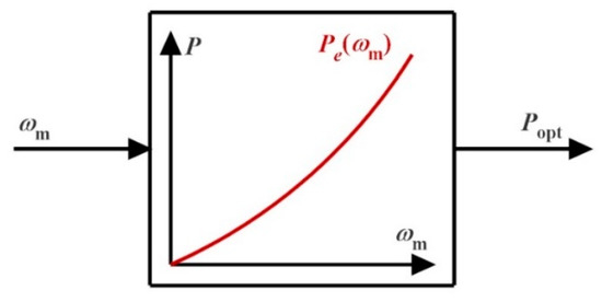
Figure 6.
Characteristic power curve-based MPPT.
6. MPPT in Wind
Figure 7 depicts the typical power–speed characteristic of a wind turbine. There are four separate operating areas based on wind speed. Because a reliable power output cannot be anticipated before the cut-in (Cin) and after the cut-off (Coff) speeds, Regions 1 and 4 are not possible, and it is not advised to operate wind turbines during these times for grid connection. The best zone for power production with WECS is now the second region between NW − Cin, and Nrated. Furthermore, only once the wind turbine runs in this area, a maximum power point operating point is achieved. The control of the mechanical output power is necessary because, in the third region (Nrated − NW − Coff), the turbine has already achieved its maximum power limit. The abovementioned discussion implies that Area 2 is the best place to apply WECS maximum power point tracking [41,42,43].
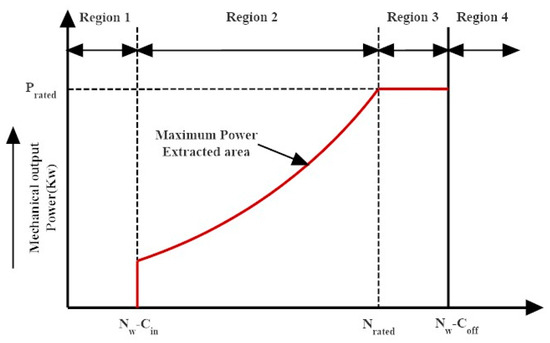
Figure 7.
Different operating regions of wind turbines are based on wind velocity.
The MPPT techniques, as previously noted, may be divided into IPC and DPC groups, as shown in Figure 8. Additionally, various cutting-edge MPPT approaches based on artificial intelligence are taken into consideration. IPC control systems use the tip speed ratio (TSR), optimum torque (OT), and power signal feedback (PSF) techniques in the context of MPPT techniques. On the other hand, the P and O, incremental conductance (INC), and optimal relation-based (ORB) MPPT techniques are used to accomplish the pre-established optimum relationship. This section provides a quick overview of several MPPT techniques [44,45].
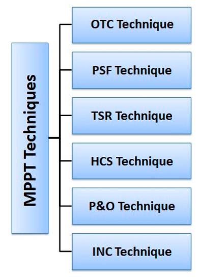
Figure 8.
Classification of MPPT Techniques.
6.1. Optimal Torque Control (OTC)-Based MPPT Technique
Figure 9 illustrates the OTC technique. The fundamental idea of this technique is to change the generator’s torque from the target wind turbine speed (WTS) to the best energy reference torque. The final speed and the ratio of TS can be used to predict turbine performance. Therefore, the wind speed may be calculated using the best torque equation as follows:
where, are rotor angular speed in rad/s, the optimal output power, optimal torque, optimal power coefficient, and air density, respectively.
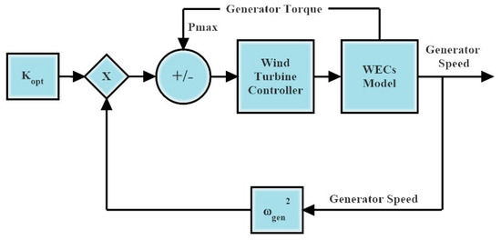
Figure 9.
OT control method.
Where Equation (3) is an analytical formulation of the OT curve that may be used to adjust mechanical torque. There aren’t many differences in terms of complexity and power between the MPPT controller and the OTC-based MPPT controller. The OT control approach is productive, quick to use, and easy to plan. OTC’s efficiency is lower than TSR because it cannot anticipate WS smoothly [46,47,48].
6.2. Power Signal Feedback (PSF)-Based MPPT Technique
PSF technology, which differs from MPPT in many ways, relies on algorithms for power sensor feedback in the absence of power signals. To find the optimal efficiency using this MPPT approach, basic training of optimal curves is necessary. Figure 10 illustrates the basic PSF block diagram. The highest force at a specific wind speed is used as the reference force in the PSF technique. Due to the need for previous knowledge of WT characteristics and wind speed data, this has led to issues [46,47,48].
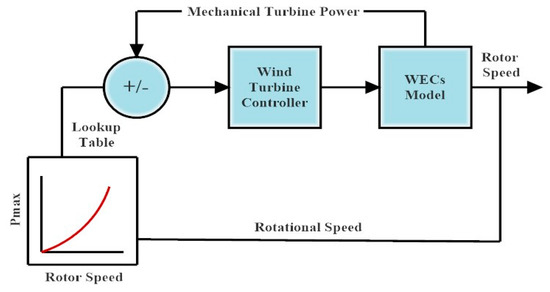
Figure 10.
Basic block diagram of PSF.
6.3. Tip Speed Ratio (TSR)-Based MPPT Technique
The MPPT approach based on tip speed ratio (TSR) is simple since experimentally anticipated straight and continuous wind movement may be considered. Independent of wind speed, the optimal TSR for a given WT is found. As shown in Figure 11, the wind speed is measured to obtain the ideal rotor speed above the ideal end speed level. Using the power and speed of the WT to estimate the approximate wind speed, the prediction approach is based on the auxiliary vector’s repulsion.
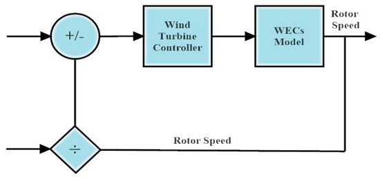
Figure 11.
Basic block illustration of TSR.
With its rapid reaction and excellent efficacy, TSR control recommends the highest efficiency. There is no way to quantify the actual wind speed. The price of the system increases due to the high cost of the ideal anemometer.
TSR can be expressed as follows:
where
ω = rotor tip speed;
V = wind speed;
r = rotor radius [46,47,48].
6.4. Hill Climb Search (HCS)-Based MPPT Technique
The inverted U-shaped graph between the power and rotor speed is used by the HCS technique of MPPT. The technique compares the current power at a given instant to the power gained at the previous step since there is a certain peak power that corresponds to a given rotor speed. To obtain the operating point closer to the peak power, the duty cycle of the gating pulse supplied to the converter switches is raised if it is discovered that the power is rising. The duty cycle is decreased if it is discovered that the power is dropping. This method’s simplicity and independence from wind turbine parameters are its main advantages. The HCS technique’s serious drawback is its inability to follow the greatest power point in situations with drastically changing wind conditions. The increments and decrements delivered to the duty cycle in conventional HCS approaches are fixed [49,50].
6.5. Perturbation and Observation (P and O)-Based MPPT Technique
The mathematical optimization approach called perturbation and observation (P and O) or hill climb searching (HCS) is used to look for the local maximum points of a given function. It is frequently used in wind energy systems to determine the ideal operating position that optimizes the energy collected. This approach is based on changing a control parameter in tiny steps and monitoring how the target function changes as a result all the way up to the point where the slope is zero. According to Figure 12, if the operating point is to the left of the peak point, the controller must change the operating point to the right to be closer to the MPPT and vice versa if it is to the right. While studying the mechanical force, some authors adjust the speed of the spin. Others keep an eye on the generator’s electrical output power while altering the inverter’s input voltage or another converter variable, such as the duty cycle, d, input current, Iin, or input voltage, Vin. Mechanical sensors are more dependable and less expensive since they are not needed in approaches that employ electrical power measurement.
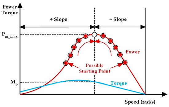
Figure 12.
Wind turbine output power and torque characteristics with MPPT tracking process [51].
The P and O approach is independent, straightforward, and adaptable since it does not require prior knowledge of the characteristic curve of a wind turbine as illustrated in Table 4. If it is utilized for big and medium inertia wind turbines, it does not, however, attain the maximum power points with fast wind fluctuations. Additionally, selecting the right step size is a difficult issue since a bigger step size results in a faster reaction time but less efficiency, whereas a smaller step size increases efficiency but slows down convergence speed [51,52,53,54].
6.6. Incremental Conductance (INC)-Based MPPT Technique
The INC technique’s independence from sensor specifications and wind turbine and generator technical requirements lowers system costs and boosts system dependability. This technique also excels at handling nonlinearity, responding dynamically, and is simple to use. The operational point of the MPPT may be identified using the power–speed slope according to the authors. If the slope is positive, the operating point is said to be on the right side of the speed–power characteristics, and if the slope is negative, the opposite is true. This technique’s weakness is that it is unstable when the inertia of the turbine varies in a variable-speed wind environment as illustrated in Table 4. A unique INC technique known as fractional order INC (FO-INC) was introduced to address the issue of instability. To reduce excessive power losses, the MPPT is tracked using a variable step size for rapidly changing feasible wind conditions [55,56,57]. Table 4 highlights the advantages and the disadvantages of the previously discussed MPPT techniques.
Table 4.
Summary of MPPT control techniques [7,34,46,50,54,57].
Table 4.
Summary of MPPT control techniques [7,34,46,50,54,57].
| MPPT Strategy | Advantages | Disadvantages |
|---|---|---|
| Optimal torque control (OTC) | OTC can give smoother output power. High efficiency and simplicity of usage. OTC can extract maximum power points from wind in wind speed-varying conditions. | OTC has slow transient responses. |
| Power signal feedback (PSF) | The PSF offers the WT reliable and economical maximum power control. It also has a quick speed of convergence and is easy to operate. | Low efficiency in variable wind conditions because it takes time to reflect changes in wind speed. |
| Tip speed ratio (TSR) measurement. | High performance and efficiency with a quick convergence rate. The best place to find it is conceptually or empirically. | High operating costs, particularly for small WT systems. It cannot give smooth output power. |
| Hill climb search (HCS) | Great adaptability, outstanding performance in a range of wind situations, and straightforward implementation. | In smaller WTs, it may result in stalling. Particularly in big and medium inertia WTs with a quick wind shift, there is a delayed reaction and inaccurate direction recognition for maximum power. |
| Perturbation and observation (P and O) | It is autonomous, straightforward, and flexible; it does not require prior knowledge of the wind turbine characteristic curve. | If it is utilized for big and medium inertia wind turbines, it is unable to attain the maximum power points during rapid wind fluctuations. |
| Incremental conductance (INC) | Improved system stability and cost savings. Simple implementation and handling of nonlinearity | High instability when there is fluctuating wind speed. |
7. Power Converters
In WECSs, the generated power is converted using power converters as shown in Figure 13. The advancement of power electronics and their use in capturing wind energy made it possible for wind turbines to run at different speeds. Standalone topology and grid-linked topology are the two primary converter topologies for power converters with PMSGs [58,59,60,61,62,63].
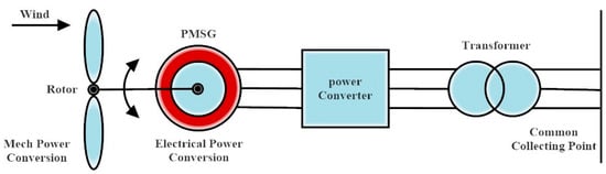
Figure 13.
Wind energy conversion system for PMSG.
7.1. Grid-Side Converter
Thyristor converters are the converters utilized on the grid side. They are mostly employed in high-power applications due to their large power capacity [58,60].
7.2. Standalone Converter
Independent converter systems often employ PWM control. Due to its ability to shut off, the IGBT is a semiconductor that is mostly used. Due to the high-frequency switching used in PWM converters, harmonics and interharmonics may be produced. To eliminate harmonics, filters are linked [58,60].
Grid-side converters are used to categorize PMSG-connected grid topologies:
- Thyristor grid-side converter;
- Hard-switched grid-side converter;
- Matrix converter;
- Multilevel converter;
- Z-source inverter [58,60,61,62].
7.2.1. Thyristor Grid-Side Converter
Continuous control of the inverter firing angle is possible with a thyristor grid-side inverter. As shown in Figure 14, thyristor grid-side inverters control turbine speed by controlling the DC link voltage to provide the most energy. The compensator is a voltage source converter (VSC), and the pulse width modulated (PWM) control is driven by the error signal between the reference and real compensator current [58,60,61,62].
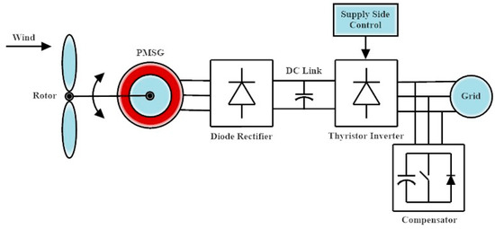
Figure 14.
Thyristor grid-side converter.
Advantages:
- Lower price and higher power rating.
Disadvantages:
- Reactive power demand requires active compensation, and total harmonic distortion must be reduced.
7.2.2. Hard-Switched Grid-Side Converter
A power mapping approach is used to match the maximum power to the DC-link voltage to maximize the system’s power output. The stator frequency is additionally managed using a derivative control, as it varies with the DC-linked voltage. The control system functions similarly to maximum power point tracking (MPPT), which converts the power generated into a reference power and uses that information to determine the operational DC voltage [58,60,61,62]. The configuration of the hard-switched grid-side converter is shown in Figure 15.
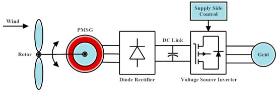
Figure 15.
Hard Switching Supply Side Inverter with Voltage Source Inverter (VSI).
Grid-side PWM converters are used with the following topologies:
Back-to-Back PWM VSI
The most traditional sort of converter is a back-to-back PWM converter which is shown in Figure 16. Because two voltage source inverters (VSI) are coupled to the generator side and grid side, it is known as a two-levels PWM-VSI converter. Two PWM-VSIs are connected via a DC link capacitor. Decoupling capacitors, also known as DC link capacitors, give the inverter distinct controls on the generator side and grid side [58,60,61,62].
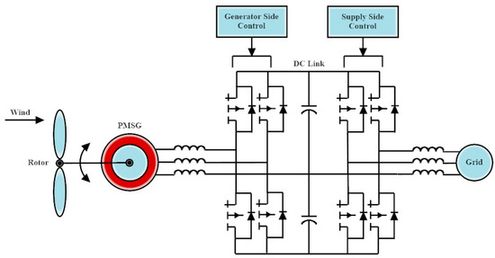
Figure 16.
Back-to-back PWM VSI converter.
Advantages:
- Lower price [58,60].
Disadvantages:
- Switching losses and high-frequency harmonic emissions.
- A decoupling capacitor shortens the system’s lifespan [58,60].
Generator-Side Uncontrolled Rectifier with the Boost Converter
This topology uses a boost converter to achieve MPPT and an unregulated rectifier to rectify the output of the PMSG as shown in Figure 17 [58,60,61,62].
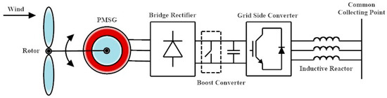
Figure 17.
Generator-side uncontrolled rectifier with boost converter [58].
Advantages:
- No need to gauge the wind.
- The controller adjusts to the PMSG’s parameter adjustments.
Generator-Side Phase-Shifting Transformer-Feeding Series Type 12 Pulse Uncontrolled Rectifier
This kind of inverter utilized an original and straightforward MPPT control method. To lessen harmonics and increase efficiency, a passive filter is connected to the generator terminal [58,60,61,62].
Advantages:
- Offer excellent efficiency and reduce voltage and current aberrations in the PMSG.
Generator-Side Semicontrolled Rectifier
The main advantages of the topology are the following:
- Simple, uncomplicated circuit design.
- There cannot be a shoot-through error.
- High performance.
- Low price [59,60,61,62].
7.2.3. Matrix Converter
The matrix converter is an alternative to both an AC–AC converter and a DC link voltage-sourced converter. Using a matrix converter’s several control levers, it is possible to separately change the output voltage magnitude, frequency, phase angle, and input power factor [58,59,60,61,63].
Advantages:
- Remove any reactive components from the DC link, such as large capacitors and/or inductors.
- No requirement for any significant energy storage component.
- High performance.
- Emission of harmonics.
Disadvantages:
- Insufficient decoupling between the converter’s two sides.
- Low gain in voltage.
- Increased conductor losses.
- It has not been accepted for industrial application due to the difficult control.
Some different types of matrix converters are the following:
Conventional Matrix Converter
Nine bidirectionally controlled insulated gate bipolar transistors (IGBTs) make up the standard matrix converter as shown in Figure 18. To adjust the output’s amplitude, frequency, phase angle, and input displacement angle, the matrix’s switches must function properly [58,60,62].
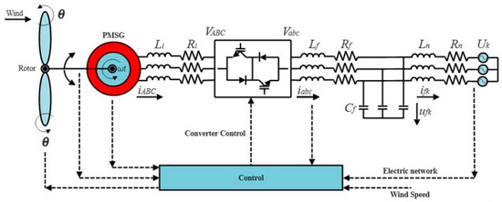
Figure 18.
Matrix converter connected between PMSG and grid.
Disadvantages:
- A commutation issue occurs while the switches are in use.
- Complicated switching is needed for the switches to operate safely.
Improved Matrix Converter
The enhanced matrix converter is built on the concept of a "fictitious DC connection," which is used to control the matrix converter. There is no energy storage component between the line side and load side converters. The second-order type filter is connected to an electrical network, the matrix converter is connected between two filters, and the PMSG is coupled with a first-order type filter [58,59,60,62].
Advantages:
- The switch-related commutation issue has been resolved.
- At zero current, all the switches on the line side turn on and off.
7.2.4. Multilevel Converter
Most applications for high-power variable wind generation employ multilevel converters shown in Figure 19. The output of a multilevel converter produces voltages with a stepped waveform and is made up of a variety of power semiconductors and capacitor voltage sources [59,61,62,63].
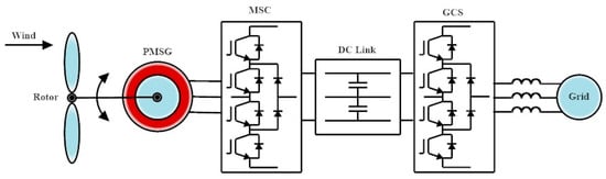
Figure 19.
Multilevel converter.
Advantages:
- Divide the overall voltage into many voltages to get lower.
- With extremely little distortion, draw input current.
- It has the ability to decrease switching losses by operating at a reduced switching frequency.
Disadvantages:
- Unbalanced voltage caused by the connection capacitor.
- High cost due to the number of switches.
- Complex control.
- Because of the features of the circuit design, switches are under uneven current stress.
7.2.5. Z-Source Inverter (ZSI)
Power delivery to the grid and maximum power tracking management is accomplished with Z-source inverters. Due to its dual voltage buck and boost characteristics, ZSI is a notion for alternative power, as discussed in Table 5 [61,62,63].
Table 5.
Comparison of types of Power Converters [59,60,61,62,63].
Advantages:
- Less susceptible to mitigating and EMI noise.
- Low harmonic distortion.
- There are fewer switching semiconductors.
- The system’s dependability is increased.
The ZSI main circuit is seen in Figure 20. It uses an X-shaped network of split inductors L1 and L2 and capacitors C1 and C2 as an impedance coupler between the power sources and the converter.
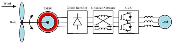
Figure 20.
Z-Source inverter (ZSI).
8. Conclusions
The history of wind energy generation across the globe and in Egypt and the many WT control approaches discussed in the literature have all been addressed in this essay, which also provides a thorough background and literature study on the topic of WT control, and a summary of the possible MPPT techniques has also been provided. In this paper, various PMGS-based generating system topologies have been examined and contrasted. It has been discovered that while the thyristorized grid-side converter topology used in PMSG-based WECS is inexpensive, it produces harmonics in the current, increasing losses and shortening the life of the generators. The most common hard-switched inverter design is back-to-back PWM VSI, although this multilevel converter saves weight and is frequently used for offshore wind farms. In comparison to previous systems, the matrix converter eliminates the DC-link step and offers a more dependable system. The matrix converter architecture is not employed in industrial applications because its involutes control and expense. Because it does not depend on the inaccurate and constantly changing wind energy power–speed characteristics, the hill climbs search technique, one of six power management systems, is better than the other five. Multilevel converters lighten the load, yet they are frequently employed in offshore wind farms. Z-source inverters increase system dependability because they can avoid shoot-through faults. Small wind energy applications employ freestanding side systems, which use the boost and buck-boost converters as their converters of choice.
Author Contributions
Conceptualization, A.R. and K.B.T.; methodology, K.B.T.; software, K.B.T.; validation, K.B.T.; investigation, K.B.T.; writing—original draft preparation, A.R. and H.Y.; writing—review and editing, K.B.T., E.T.E. and E.E.E.-K.; visualization, A.R. and H.Y.; supervision, E.T.E. and E.E.E.-K. All authors have read and agreed to the published version of the manuscript.
Funding
This research received no external funding.
Conflicts of Interest
The authors declare no conflict of interest.
References
- Beurskens, J. The history of wind energy. In Understanding Wind Power Technology: Theory, Deployment and Optimisation; John Wiley & Sons: Hoboken, NJ, USA, 2014; pp. 1–44. [Google Scholar]
- Wagner, H.J. Introduction to wind energy systems. In EPJ Web Conferences; EDP Sciences: Les Ulis, France, 2020; Volume 246, p. 00004. [Google Scholar]
- Infield, D.; Freris, L. Renewable Energy in Power Systems; John Wiley & Sons: Hoboken, NJ, USA, 2020. [Google Scholar]
- Jenkins, N.; Burton, T.L.; Bossanyi, E.; Sharpe, D.; Graham, M. Wind Energy Handbook; John Wiley & Sons: Hoboken, NJ, USA, 2021. [Google Scholar]
- Kesraoui, M.; Korichi, N.; Belkadi, A. Maximum power point tracker of wind energy conversion system. Renew. Energy 2011, 36, 2655–2662. [Google Scholar] [CrossRef]
- Husain, M.A.; Tariq, A. Modeling and study of a standalone PMSG wind generation system using MATLAB/SIMULINK. Univers. J. Electr. Electron. Eng. 2014, 2, 270–277. [Google Scholar] [CrossRef]
- Nasiri, M.; Milimonfared, J.; Fathi, S.H. Modeling, analysis and comparison of TSR and OTC methods for MPPT and power smoothing in permanent magnet synchronous generator-based wind turbines. Energy Convers. Manag. 2014, 86, 892–900. [Google Scholar] [CrossRef]
- Mezzai, N.; Rekioua, D.; Rekioua, T. Control of Wind Energy Conversion System based on PMSG. In Proceedings of the 2017 International Renewable and Sustainable Energy Conference (IRSEC), Tangier, Morocco, 4–7 December 2017. [Google Scholar]
- Mousavi, Y.; Bevan, G.; Kucukdemiral, I.B.; Fekih, A. Sliding mode control of wind energy conversion systems: Trends and applications. Renew. Sustain. Energy Rev. 2022, 167, 112734. [Google Scholar] [CrossRef]
- Almihat, M.G.M.; Kahn, M.T. Wind Turbines Control Trends and Challenges: An Overview. Int. J. Innov. Res. Sci. Stud. 2022, 5, 378–390. [Google Scholar] [CrossRef]
- Yao, Q.; Hu, Y.; Liu, J.; Zhao, T.; Qi, X.; Sun, S. Power Curve Modeling for Wind Turbine using Hybrid-Driven Outlier Detection Method. J. Mod. Power Syst. Clean Energy 2022, 1–11. [Google Scholar] [CrossRef]
- Zhang, X.; Jia, J.; Zheng, L.; Yi, W.; Zhang, Z. Maximum power point tracking algorithms for wind power generation system: Review, comparison and analysis. Energy Science. Eng. 2022, 11, 430–444. [Google Scholar] [CrossRef]
- Alkul, O.; Syed, D.; Demirbas, S. A Review of Wind Energy Conversion Systems. In Proceedings of the 2022 10th International Conference on Smart Grid (icSmartGrid), Istanbul, Turkey, 27–29 June 2022. [Google Scholar]
- Zhang, S. Investigations of Grid-Connected Wind Power System: Low Voltage Ride through and Power Quality Issues. Ph.D. Thesis, Nanyang Technological University, Singapore, 2011. [Google Scholar]
- Beainy, A.; Maatouk, C.; Moubayed, N.; Kaddah, F. Comparison of different types of generator for wind energy conversion system topologies. In Proceedings of the 2016 3rd International Conference On Renewable Energies for Developing Countries (REDEC), Zouk Mosbeh, Lebanon, 13–15 July 2016. [Google Scholar]
- Ali, M.H. Wind Energy Systems: Solutions for Power Quality and Stabilization; CRC Press: Boca Raton, FL, USA, 2012. [Google Scholar]
- Ackermann, T.; Söder, L. Wind energy technology and current status: A review. Renew. Sustain. Energy Rev. 2000, 4, 315–374. [Google Scholar] [CrossRef]
- Tawfiq, K.B.; Mansour, A.S.; Ibrahim, M.N.; El-Kholy, E.E.; Sergeant, P. Implementation of Matrix Converter in Wind Energy Conversion System with Modified Control Techniques. Electric Power Components and Systems 2019, 47, 1316–1331. [Google Scholar] [CrossRef]
- Moran, M.J.; Shapiro, H.N.; Boettner, D.D.; Bailey, M.B. Fundamentals of Engineering Thermodynamics; John Wiley & Sons: Hoboken, NJ, USA, 2010. [Google Scholar]
- Liljestrom, K.W. Integrating Horizontal and Vertical Axis Wind Turbines for a Point Conversion. Ph.D. Thesis, San Diego State University, San Diego, CA, USA, 2016. [Google Scholar]
- Zobaa, A.F.; Bansal, R.C. (Eds.) Handbook of Renewable Energy Technology; World Scientific: Singapore, 2011. [Google Scholar]
- Rao, K.R. Wind Energy for Power Generation: Meeting the Challenge of Practical Implementation; Springer Nature: Berlin/Heidelberg, Germany, 2019. [Google Scholar]
- Yousef, A.; Nasiri, A.; Abdelbaqi, O. Wind turbine level energy storage for low voltage ride through (LVRT) support. In Proceedings of the 2014 IEEE Symposium on Power Electronics and Machines for Wind and Water Applications, Milwaukee, WI, USA, 24–26 July 2014. [Google Scholar]
- El-Sharkawi, M.A. Wind Energy: An Introduction; CRC Press: Boca Raton, FL, USA, 2015. [Google Scholar]
- Tawfiq, K.B.; Mansour, A.S.; Ramadan, H.S.; Becherif, M.; El-Kholy, E.E. Wind energy conversion system topologies and converters: Comparative review. Energy Procedia 2019, 162, 38–47. [Google Scholar] [CrossRef]
- Johari, M.K.; Jalil, M.; Shariff, M.F.M. Comparison of horizontal axis wind turbine (HAWT) and vertical axis wind turbine (VAWT). Int. J. Eng. Technol. 2018, 7, 74–80. [Google Scholar] [CrossRef]
- Palomino Ramirez, H. An Economic Assessment of Micro-Scale Use of Renewable Energy Sources: Two Case Studies. 2015. Available online: http://urn.fi/URN:NBN:fi:jyu-201510073332 (accessed on 1 November 2022).
- Available online: https://aeeolica.org/en/about-wind-energy/wind-energy-in-the-world/ (accessed on 1 November 2022).
- “Wind Data”. Available online: http://www.thewindpower.net/country_list_en.php (accessed on 1 November 2022).
- Available online: https://www.enerdata.net/publications/daily-energy-news/global-wind-capacities-increased-94-gw-2021-837-gw.html (accessed on 1 November 2022).
- Kumar, D.; Chatterjee, K. A review of conventional and advanced MPPT algorithms for wind energy systems. Renew. Sustain. Energy Rev. 2016, 55, 957–970. [Google Scholar] [CrossRef]
- Bekiroglu, E.; Yazar, M.D. MPPT Control of Grid Connected DFIG at Variable Wind Speed. Energies 2022, 15, 3146. [Google Scholar] [CrossRef]
- Zhang, Y.; Zhang, L.; Liu, Y. Implementation of maximum power point tracking based on variable speed forecasting for wind energy systems. Processes 2019, 7, 158. [Google Scholar] [CrossRef]
- Apata, O.; Oyedokun, D.T.O. An overview of control techniques for wind turbine systems. Sci. Afr. 2020, 10, e00566. [Google Scholar] [CrossRef]
- Rosmin, N. Internal Model Control (IMC) Design for a Stall-Regulated Variable-Speed Wind Turbine System. Ph.D. Thesis, Loughborough University, Loughborough, UK, 2015. [Google Scholar]
- Deode, D.; Kishore, N. A Review on Performance Analysis of PMSG in Wind Energy Conversion System. Int. J. Eng. Innov. Technol. (IJEIT) 2016, 5, 42–49. [Google Scholar]
- Chaudhuri, A.; Datta, R.; Kumar, M.P.; Davim, J.P.; Pramanik, S. Energy conversion strategies for wind energy system: Electrical, mechanical and material aspects. Materials 2022, 15, 1232. [Google Scholar] [CrossRef]
- Hiremath, R.; Moger, T. Comprehensive review on low voltage ride through capability of wind turbine generators. Int. Trans. Electr. Energy Syst. 2020, 30, e12524. [Google Scholar] [CrossRef]
- Wagner, H.J.; Mathur, J. Introduction to Wind Energy Systems: Basics, Technology and Operation; Springer: Berlin/Heidelberg, Germany, 2018. [Google Scholar]
- Zou, Y.; Elbuluk, M.; Sozer, Y. Stability analysis of maximum power point tracking (MPPT) method in wind power systems. IEEE Trans. Ind. Appl. 2013, 49, 1129–1136. [Google Scholar] [CrossRef]
- Ram, J.P.; Rajasekar, N.; Miyatake, M. Design and overview of maximum power point tracking techniques in wind and solar photovoltaic systems: A review. Renew. Sustain. Energy Rev. 2017, 73, 1138–1159. [Google Scholar] [CrossRef]
- Abdullah, M.A.; Yatim, A.H.M.; Tan, C.W.; Saidur, R. A review of maximum power point tracking algorithms for wind energy systems. Renew. Sustain. Energy Rev. 2012, 16, 3220–3227. [Google Scholar] [CrossRef]
- Malik, M.Z.; Baloch, M.H.; Gul, M.; Kaloi, G.S.; Chauhdary, S.T.; Memon, A.A. A research on conventional and modern algorithms for maximum power extraction from wind energy conversion system: A review. Environ. Sci. Pollut. Res. 2021, 28, 5020–5035. [Google Scholar] [CrossRef]
- Mousa, H.H.; Youssef, A.R.; Mohamed, E.E. State of the art perturb and observe MPPT algorithms-based wind energy conversion systems: A technology review. Int. J. Electr. Power. Energy Syst. 2021, 126, 106598. [Google Scholar] [CrossRef]
- Mishra, S.; Shukla, S.; Verma, N. Comprehensive review on maximum power point tracking techniques: Wind energy. In Proceedings of the 2015 Communication Control and Intelligent Systems (CCIS), Mathura, India, 7–8 November 2015; pp. 464–469. [Google Scholar]
- Koondhar, M.A.; Ali, M.; Keerio, M.U.; Junejo, A.K.; Laghari, I.A.; Chandio, S. Wind energy conversion system using maximum power point tracking technique—A comprehensive survey. Appl. Eng. Lett. 2021, 6, 148–156. [Google Scholar] [CrossRef]
- Hussain, M.; Baloch, M.H.; Memon, A.H.; Pathan, N.K. Maximum power tracking system based on power electronic topology for wind energy conversion system applications. Eng. Technol. Appl. Sci. Res. 2018, 8, 3392–3397. [Google Scholar] [CrossRef]
- Pande, J.; Nasikkar, P.; Kotecha, K.; Varadarajan, V. A review of maximum power point tracking algorithms for wind energy conversion systems. J. Mar. Sci. Eng. 2021, 9, 1187. [Google Scholar] [CrossRef]
- Badawi, A.; Hasbullah, N.F.; Yusoff, S.H.; Aisha, H.; Zyoud, A. Novel technique for hill climbing search to reach maximum power point tracking. Int. J. Power Electron. Drive Syst. (IJPEDS) 2020, 11, 2019. [Google Scholar] [CrossRef]
- Zebraoui, O.; Bouzi, M. Comparative Study of Different MPPT Methods for Wind Energy Conversion System. Int. J. Trend Innov. Res. (IJTIIR) 2021, 3. [Google Scholar] [CrossRef]
- Abdullah, M.A.; Yatim, A.H.M.; Tan, C.W. A study of maximum power point tracking algorithms for wind energy system. In Proceedings of the 2011 IEEE Conference on Clean Energy and Technology (CET), Kuala Lumpur, Malaysia, 27–29 June 2011. [Google Scholar]
- Dursun, E.H.; Kulaksiz, A.A. MPPT control of PMSG based small-scale wind energy conversion system connected to DC-bus. Int. J. Emerg. Electr. Power Syst. 2020, 21, 1–13. [Google Scholar] [CrossRef]
- Fatah, A.; Benlaloui, I.; Mechnane, F.; Boutabba, T.; Khamari, D.; Drid, S.; Chrifi-Alaoui, L. A Modified Perturbe and Observe MPPT Technique for Standalone Hybrid PV-Wind with Power Management. In Proceedings of the 2021 International Conference on Control. Automation and Diagnosis (ICCAD), Grenoble, France, 3–5 November 2021. [Google Scholar]
- Youssef, A.R.; Mousa, H.H.; Mohamed, E.E. Development of self-adaptive P&O MPPT algorithm for wind generation systems with concentrated search area. Renew. Energy 2020, 154, 875–893. [Google Scholar]
- Govinda Chowdary, V.; Udhay Sankar, V.; Mathew, D.; Hussaian Basha, C.H.; Rani, C. Hybrid fuzzy logic-based MPPT for wind energy conversion system. In Soft Computing for Problem Solving; Springer: Singapore, 2020; pp. 951–968. [Google Scholar]
- Tidhaf, B. A New Maximum Power Point Tracking Based on Neural Networks and Incremental Conductance for Wind Energy Conversion System. In E3S Web of Conferences; EDP Sciences: Les Ulis, France, 2022; Volume 336, p. 00055. [Google Scholar]
- Ridwan, M.; Pradipta, A.; Anam, S.; Ashari, M. Comparison of P&O and inceremental conductance based maximum power point tracking for wind turbine application in remote area (Case study: Gili genting Island, Madura, East Java, Indonesia). In Proceedings of the 2018 IEEE International Conference on Innovative Research and Development (ICIRD), Bangkok, Thailand, 11–12 May 2018. [Google Scholar]
- Devika, M.; Geetha, R.; Hemalatha, G. A Review on Power Converter Topology for Wind Energy System for Permanent Magnet Synchronous Generator. Int. J. Electron. Commun. Comput. Eng. 2017, 8, 22–25. [Google Scholar]
- Melício, R.; Mendes, V.M.; Catalão, J.P. Wind Turbines with Permanent Magnet Synchronous Generator and Full-Power Converters: Modelling, Control and Simulation. In Wind Turbines; IntechOpen: London, UK, 2011; pp. 465–470. [Google Scholar]
- Devika, M.; Geetha, R. Wind Energy System for Permanent Magnet Synchronous Generator using Power Converter Topology. Int. J. Trend Res. Dev. 2017, 4, 105–108. [Google Scholar]
- Jamil, M.; Gupta, R.; Singh, M. A review of power converter topology used with PMSG based wind power generation. In Proceedings of the 2012 IEEE Fifth Power India Conference, Murthal, India, 19–22 December 2012; pp. 1–6. [Google Scholar]
- Yadav, R.; Thombre, A.D. Review of PMSG Based Distributed Generation System. Int. J. Electr. Electron. Data Commun. 2017, 5, 13–17. [Google Scholar]
- Tripathi, S.M.; Tiwari, A.N.; Singh, D. Grid-integrated permanent magnet synchronous generator-based wind energy conversion systems: A technology review. Renew. Sustain. Energy Rev. 2015, 51, 1288–1305. [Google Scholar] [CrossRef]


Disclaimer/Publisher’s Note: The statements, opinions and data contained in all publications are solely those of the individual author(s) and contributor(s) and not of MDPI and/or the editor(s). MDPI and/or the editor(s) disclaim responsibility for any injury to people or property resulting from any ideas, methods, instructions or products referred to in the content. |
© 2023 by the authors. Licensee MDPI, Basel, Switzerland. This article is an open access article distributed under the terms and conditions of the Creative Commons Attribution (CC BY) license (https://creativecommons.org/licenses/by/4.0/).