
Applications of Supercritical Water in Waste Treatment and Valorization: A Review


 ,
, 

 and
and
Abstract
1. Introduction
2. Properties of Supercritical Water
3. Supercritical and Subcritical Water Applications
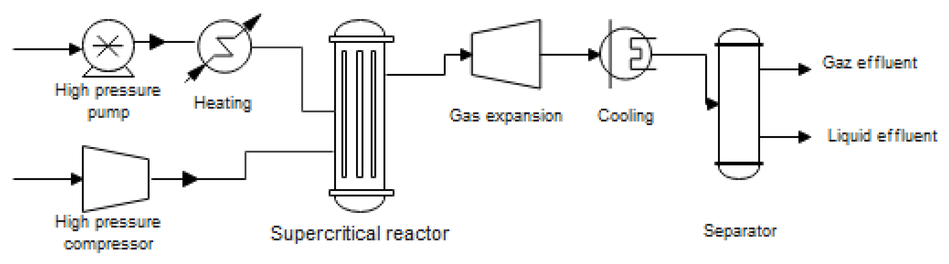
3.1. SCWO Process
3.1.1. Preparation of Feed and Pressurization
3.1.2. The Reaction
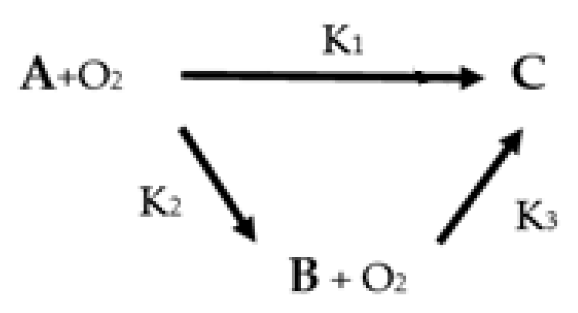
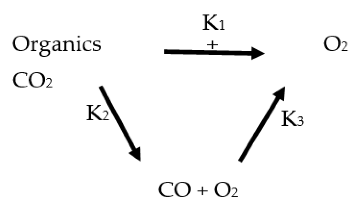
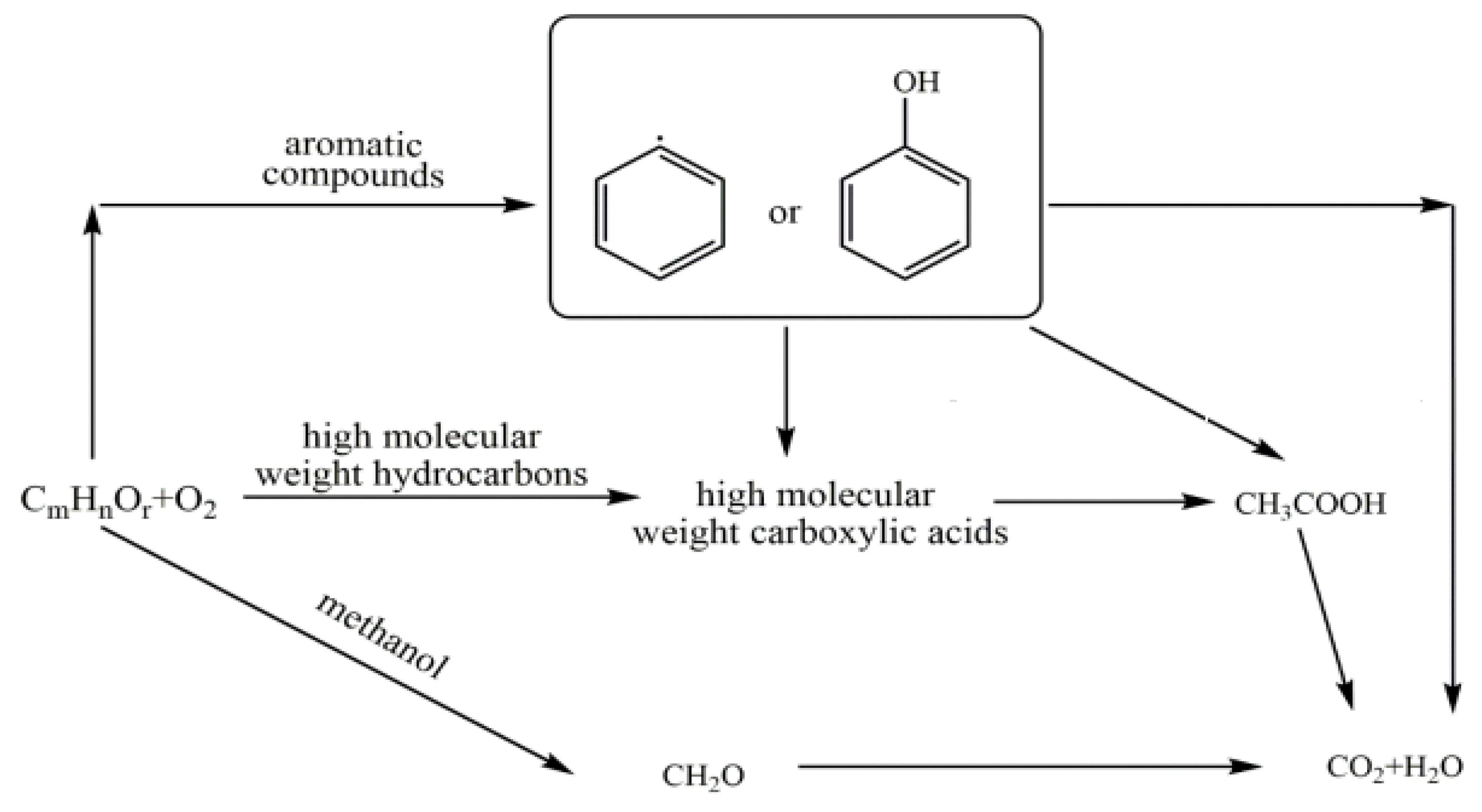
3.1.3. Chemical Kinetics of the Oxidation Reaction
3.1.4. Formation and Separation of Salts
3.1.5. Cooling and Heat Recovery
4. Supercritical Water Oxidation Reactor
5. CFD Modeling of SCWO Reactor
5.1. The Hydrodynamics
- -
- Conservation of Mass
- -
- Conservation of Momentum
5.2. Conservation of Species
5.3. The Heat Transfer
Heat Transfer Coefficient for SCWO Reactors
6. Problems with SCWO and Suggested Solutions in Literature
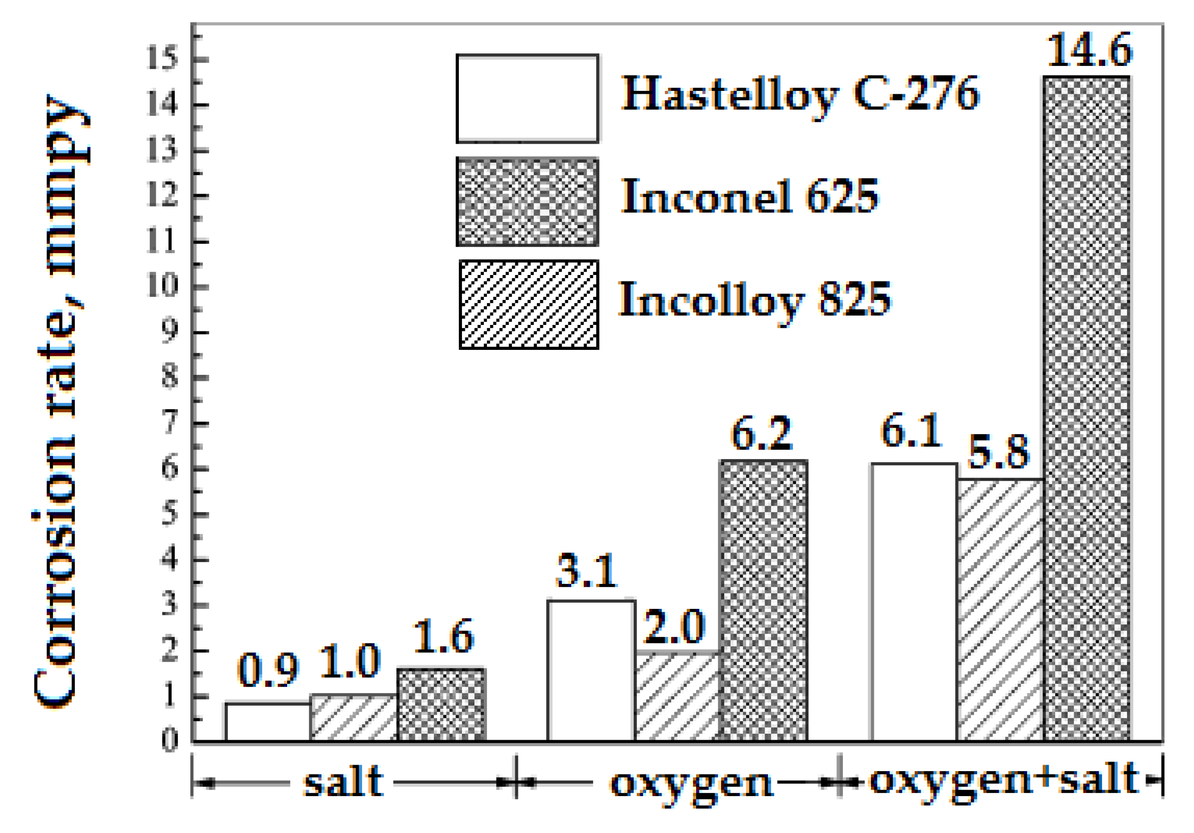
6.1. Corrosion
6.2. Salts Precipitation
6.3. Energy Recovery Solution
7. Conclusions
Funding
Data Availability Statement
Conflicts of Interest
References
- Pourmortazavi, S.M.; Saghafi, Z.; Ehsani, A.; Yousefi, M. Application of supercritical fluids in cholesterol extraction from foodstuffs: A review. J. Food Sci. Technol. 2018, 55, 2813–2823. [Google Scholar] [CrossRef] [PubMed]
- Aymonier, C. Traitement Hydrothermal de Déchets Industriels Spéciaux. Données Pour le Dimensionnement D’installations Industrielles et Concepts Innovants de Réacteurs Sonochimique et Électrochimique. Ph.D. Thesis, Université Sciences et Technologies-Bordeaux, Bordeaux France, 2000. [Google Scholar]
- Perrut, M. Supercritical fluid applications: Industrial developments and economic issues. Ind. Eng. Chem. Res. 2000, 39, 4531–4535. [Google Scholar] [CrossRef]
- Tarczykowska, A. Green solvents. J. Educ. Health Sport 2017, 7, 224–232. [Google Scholar]
- Hrncic, M.K.; Cor, D.; Verboten, M.T.; Knez, Z. Application of supercritical and subcritical fluids in food processing. Food Qual. Saf. 2018, 2, 59–67. [Google Scholar] [CrossRef]
- Chen, F.; Chen, J.H.; Wu, S.; Rong, S. Cod Removal Efficiency of Aromatic Compounds in Supercritical Water. In Proceedings of the China-Japan International Academic Symposium, Sendai, Japan, 6 March 2000; pp. 115–122. [Google Scholar]
- Benjumea, T.J.M. Diseño y Optimización de Plantas de Oxidación en Agua Supercrítica: Aplicación a Residuos Agroalimentarios. Ph.D. Thesis, University of Cádiz, Cádiz, Spain, 2017. [Google Scholar]
- Sengers, J.M.H.L.; Erdogan, K. (Eds.) Supercritical Fluids: Fundamentals for Application; Kluwer Academic Publishers: New York, NY, USA, 1994. [Google Scholar]
- Benmakhlouf, N.; Outili, N.; Meniai, A.-H. Modeling of hydrothermal oxidation in supercritical water oxidation with energy recovery. In Proceedings of the 2016 7th International Renewable Energy Congress (IREC), Hammamet, Tunisia, 22–24 March 2016. [Google Scholar]
- Outili, N.; Benmakhlouf, N. An energy recovery study of acetic acid wet air oxidation process. In Proceedings of the 2015 3rd International Renewable and Sustainable Energy Conference (IRSEC), Marrakech, Morocco, 10–13 December 2015. [Google Scholar]
- Lachos-Perez, D.; Brown, A.B.; Mudhoo, A.; Martinez, J.; Timko, M.T.; Rostagno, M.A.; Forster-Carneiro, T. Applications of subcritical and supercritical water conditions for extraction, hydrolysis, gasification, and carbonization of biomass: A critical review. Biofuels 2017, 14, 611–626. [Google Scholar] [CrossRef]
- Available online: http://www.portail-fluides-supercritiques.com/fileadmin/userupload/Flash_Infos/IFS_Lettre_info_N°8 (accessed on 1 December 2011).
- Gandhi, K.; Sumit, A.; Kumar, A. Industrial applications of supercritical fluid extraction: A review. Int. J. Chem. Stud. 2017, 5, 336–340. [Google Scholar]
- Oh, C.H. Hazardous and Radioactive Waste Treatment Technologies Handbook, 1st ed.; CRC Press: Boca Raton, FL, USA, 2001. [Google Scholar]
- Uematsu, M.; Frank, E.U. Static Dielectric Constant of Water and Steam. Phys. Chem. Ref. Data 1980, 9, 1291–1306. [Google Scholar] [CrossRef]
- Loppinet-Serani, A.; Cansell, F.; Frédéric, M.; Mercadier, J. Hydrothermal oxidation of industrial wastewater: An environmental friendly process. In Récents Progrès en Génie des Procédés; Société Française du Génie des Procédés (SFGP): St Etienne, France, 2007. [Google Scholar]
- Swallow, K.C.; Killilea, W.R.; Malinowski, K.C.; Staszak, C.N. The modar process for the destruction of hazardous organic wastes—Field test of a pilot-scale unit. J. Waste Manag. 1989, 9, 19–26. [Google Scholar] [CrossRef]
- Thomason, T.B.; Hong, G.T.; Swallow, K.C.; Killilea, W.R. The Modar supercritical water oxidation process. Innov. Waste Treat. Technol. Ser. 1990, I, 31–42. [Google Scholar]
- Bermejo, M.D.; Rincon, D.; Vazquez, V.; Cocero, J.M. Supercritical water oxidation fundamentals and reactor modeling. Chem. Ind. Chem. Eng. Q. 2007, 13, 79–87. [Google Scholar] [CrossRef]
- Marrone, P.A. Supercritical water oxidation-current status of full-scale commercial activity for waste destruction. J. Supercrit Fluids 2013, 79, 283–288. [Google Scholar] [CrossRef]
- Marrone, P.A.; Lachance, R.P.; DiNaro, J.L.; Phenix, B.Q.; Meyer, J.C.; Tester, J.; Peters, W.; Swallow, K.C. Methylene chloride oxidation and hydrolysis in supercritical water as a means of remediation. ACS Symp. Ser. 1995, 608, 197–216. [Google Scholar]
- Moussiere, S. Etude par Simulation Numérique des Ecoulements Turbulents Réactifs dans les Réacteurs d’Oxydation Hydrothermale: Application à un Réacteur Agité Double Enveloppe. PhD Thesis, Université Aix-Marseille-3 Paul Cézanne, Aix-en-Provence, France, 2006. [Google Scholar]
- Savage, P.E.; Gopalan, S.; Mizan, T.I.; Martino, C.J.; Brock, E.E. Reactions at Supercritical Conditions: Applications and Fundamentals. AIChE J. 1995, 41, 1723–1778. [Google Scholar] [CrossRef]
- Mancini, F.; Cansell, F.; Marias, F.; Mercadier, J. Hydrothermal oxidation of waste from biomass to generate energy. In Proceedings of the Oral Communication in WasteEng, Albi, France, 17–19 May 2005. [Google Scholar]
- Joussot-Dubien, M.C. Etude de L’oxydation Hydrothermal de Déchets Organiques, Cas de Deux Molécules Modèles: Le Dodécane et le Méthanol. Ph.D. Thesis, Université de Bordeaux 1, Bordeaux, France, 1996. [Google Scholar]
- Moussiere, S.; Joussot-Dubien, C.; Guichardon, P.; Boutin, O.; Turc, H.-A.; Roubaud, A.; Fournel, B. Modeling of heat transfer and hydrodynamic with two kinetics approaches during supercritical water oxidation process. J. Supercrit. Fluids 2007, 43, 324–332. [Google Scholar] [CrossRef]
- Giulia, G.; Ding Pan, D. A closer look at supercritical water. Proc. Natl. Acad. Sci. USA 2013, 110, 6250–6251. [Google Scholar]
- Marulanda, V. Reacting flow simulations of supercritical water oxidation of BCB-contaminated transformer oil in a pilot plant reactor. J. Chem. Eng. 2011, 28, 285–294. [Google Scholar]
- Loppinet-Serani, A.; Aymonier, C.; Cansell, F. Supercritical water for environmental technologies. J. Chem. Technol. Biotechnol. 2010, 85, 583–589. [Google Scholar] [CrossRef]
- Japas, M.L.; Franck, E.U. High Pressure Phase Equilibria and P VT-Data of the Water-Oxygen System Including Water-Air to 673 K and 250 MPa. Ber. Bunsenges. Phys. Chem. 1985, 89, 1268–1275. [Google Scholar] [CrossRef]
- Fernandez-Prini, R. High-Temperature Aqueous Solutions: Thermodynamic Properties, 1st ed.; CRC Press: Boca Raton, FL, USA, 1991. [Google Scholar]
- Cocero, M.J. Supercritical Water Oxidation (SCWO). Application to industrial wastewater treatment. High Pressure in Chemical Engineering. Fundam. Appl. 2001, 9, 509–526. [Google Scholar]
- Fourcault, A.; García-Jarana, B.; Sánchez-Oneto, J.; Marias, F.; Portela, J.R. Supercritical water oxidation of phenol with air. Experimental results and modeling. Chem. Eng. J. 2009, 152, 227–233. [Google Scholar] [CrossRef]
- Mercadier, J.; Marias, F.; Vielcazals, S.; Mancini, F.; Bottreau, M.; Cansell, F. Supercritical Water Oxidation of Organic Compounds: Experimental and Numerical Results. Environ. Eng. Sci. 2007, 24, 1379–1388. [Google Scholar] [CrossRef]
- Vielcazals, S.; Mercadier, J.; Marias, F.; Matéos, D.; Bottreau, M.; Cansell, F.; Marraud, C. Modeling and simulation of hydrothermal oxidation of organic compounds. AIChE J. 2006, 52, 818–825. [Google Scholar] [CrossRef]
- Bermejo, M.D.; Fdez-Polanco, F.; Cocero, M.J. Transpiring Wall Reactor for the Supercritical Water Oxidation Process: Operational Results, Modeling and Scaling. In Proceedings of the 10th European Meeting on Supercritical Fluids, Reactions, Materials and Natural Products Processing, Colmar, France, 12 December 2005. [Google Scholar]
- Sengers, J.V.; Watson, J.T.R. Improved international formulations for the viscosity and thermal conductivity of water substance. J. Phys. Chem. Ref. Data 1986, 15, 1291–1312. [Google Scholar] [CrossRef]
- Chung, T.H.; Ajlan, M.; Lee, L.L.; Starling, K.E. Generalized Multiparameter Correlation for Nonpolar and Polar Fluid Transport Properties. Ind. Eng. Chem. Res. 1988, 27, 671–679. [Google Scholar] [CrossRef]
- Wagner, W.; Kretzschmar, H.-J. International Steam Tables, Properties of Water and Steam Based on the Industrial Formulation IAPWS; Springer: Berlin/Heidelberg, Germany, 1998. [Google Scholar]
- Benmakhlouf, N.; Outili, N.; Meniai, A.-H. Modeling and optimization of phenol hydrothermal oxidation in supercritical water. Int. J. Hydrog. Energy 2016, 42, 12926–129328. [Google Scholar]
- Withag, J.A.M.; Sallevelt, J.L.H.P.; Brilman, D.W.F.; Bramer, E.A.; Brem, G. Heat transfer characteristics of supercritical water in a tube: Application for 2D and an experimental validation. J. Supercrit. Fluids 2012, 70, 156–170. [Google Scholar] [CrossRef]
- Serin, J.P.; Mercadier, J.; Marias, F.; Cezac, P.; Cansell, F. Use of CFD for the Design of Injectors for Supercritical Water Oxidation. 2014. Available online: https://www.isasf.net/fileadmin/files/Docs/Colmar/Paper/Rw9.pdf (accessed on 1 December 2022).
- Miguel, H.; Cifuentes, A.; Ibañez, E. Sub-and supercritical fluid extraction of functional ingredients from different natural sources: Plants, food-by-products, algae and microalgae: A review. Food Chem. 2006, 98, 136–148. [Google Scholar]
- Hanna, P.; Wolak, P.; Złocińska, A. Hydrothermal decomposition of xylan as a model substance for plant biomass waste–hydrothermolysis in subcritical water. Biomass Bioenergy 2011, 35, 3902–3912. [Google Scholar]
- Marta, S.; Fuertes, A.B. Chemical and structural properties of carbonaceous products obtained by hydrothermal carbonization of saccharides. Chem. Eur. J. 2009, 15, 4195–4203. [Google Scholar]
- Marta, S.; Fuertes, A.B.; Mokaya, R. High density hydrogen storage in superactivated carbons from hydrothermally carbonized renewable organic materials. Energy Environ. Sci. 2011, 4, 1400–1410. [Google Scholar]
- Houcinat, I.; Outili, N.; Meniai, A.-H. Parametric study via full factorial design for glycerol supercritical gasification. Biofuels 2019, 13, 265–278. [Google Scholar]
- Istok, G.N.; Zasetsky, A.Y.; Svishchev, I.M. Nucleation of NaCl nanoparticles in supercritical water: Molecular dynamics simulations. J. Phys. Chem. 2008, 112, 7537–7543. [Google Scholar]
- Bagheri, H.; Soltani, R.; Shahmirzaei, M.; Yahyanejad, M.; Fijani, F.; Hashemipour, H. Nanotechnology and supercritical fluids. J. Fund. Appl. Sci. 2016, 8, 839–859. [Google Scholar]
- Benjamin, K.E.; Savage, P.E. Supercritical Water Oxidation of Methylamine. Ind. Eng. Chem. Res 2005, 44, 5318–5324. [Google Scholar] [CrossRef]
- Hatakeda, K.; Ikushima, Y.; Sato, O.; Aizawa, T.; Saito, N. Supercritical water oxidation of polychlorinated biphenyls using hydrogen peroxide. Chem. Eng. Sci. 1999, 54, 3079–3084. [Google Scholar] [CrossRef]
- Bermejo, M.D.; Cocero, M.J. Supercritical Water Oxidation: A Technical Review. AIChE J. 2006, 52, 3933–3951. [Google Scholar] [CrossRef]
- Turbosystems Engineering. Overview of Supercritical Water Oxidation (SCWO); Turbosystems Engineering: San Rafael, CA, USA, 2004. [Google Scholar]
- Leybros, A. Etude de la Destruction de Systèmes Polyphasiques en Milieu Eau Supercritique. Ph.D. Thesis, Université de Marseille III, Marseille, France, 2009. [Google Scholar]
- Dubois, M.-A.; Dozol, J.; Massiani, C.; Ambrosio, M. Reactivities of polystyrenic polymers with supercritical water under nitrogen or air. Identification and formation of degradation compounds. Ind. Eng. Chem. Res. 1996, 35, 2743–2747. [Google Scholar] [CrossRef]
- Akai, Y.; Yamada, K.; Sako, T. Ion-exchange resin decomposition in supercritical water. High Press. Res. 2001, 20, 515–524. [Google Scholar] [CrossRef]
- Barnes, C.M. Evaluation of Tubular Reactor Designs for Supercritical Water Oxidation of U.S. Department of Energy Mixed Waste; Lockheed Idaho Technologies Co.: Idaho Falls, ID, USA, 1994. [Google Scholar]
- Gidner, A.; Stenmark, L. Supercritical Water Oxidation of Sewage Sludge-State of Art; Chematur Engineering AB: Karlskoga, Sweden, 2000. [Google Scholar]
- Lixiong, L.; Chen, P.; Gloyna, E.F. Generalized kinetic model for wet oxidation of organic compounds. AIChE J. 1991, 37, 1687–1697. [Google Scholar]
- Hornton, T.D.; Savage, P.E. Kinetics of phenol oxidation in supercritical water. AIChE J. 1992, 38, 321–327. [Google Scholar] [CrossRef]
- Portela, J.R.; Nebot, E.; Martinez de la Ossa, E. Generalized kinetic models for supercritical water oxidation of cutting oil wastes. J. Supercrit. Fluids 2001, 21, 135–145. [Google Scholar] [CrossRef]
- Zhang, F.; Chen, S.; Xu, C.; Chen, G.; Ma, C. Energy consumption and exergy analyses of a supercritical water oxidation system with a transpiring wall reactor. Energy Converv. Manag. 2017, 145, 82–92. [Google Scholar] [CrossRef]
- Sànchez-Oneto, J.; Portela, J.R.; Nebot, E.; Martinez de la Ossa, E. Hydrothermal oxidation: Application to the treatment of different cutting fluid wastes. J. Hazard. Mater. 2007, 144, 639–644. [Google Scholar] [CrossRef] [PubMed]
- Vadillo, V.; Belin Garcia-Jarana, M.; Sànchez-Oneto, J.; Portela, J.R.; Martinez de la Ossa, E. Simulation of real waste water supercritical water oxidation at high concentration on a pilot plant scale. Ind. Eng. Chem. Res. 2011, 50, 12512–12520. [Google Scholar] [CrossRef]
- Sanchez-Oneto, J.; Mancini, F.; Portela, J.R.; Nebot, E.; Cansell, F.; Martınez de la Ossa, E. Kinetic model for oxygen concentration dependence in the supercritical water oxidation of an industrial wastewate. Chem. Eng. J. 2008, 144, 361–367. [Google Scholar] [CrossRef]
- Benjumea, J.M.; Sanchez-Oneto, J.; Portela, J.R.; Jiménez-Espadafor, F.J.; de la Ossa, E.M. Simulation of supercritical water oxidation reactor in transitory state: Application to time-dependent processes. J. Supercrit. Fluids 2016, 117, 219–229. [Google Scholar] [CrossRef]
- Zhou, L.; Wang, S.; Ma, H.; Gong, Y.; Xu, D. Oxidation of Cu(II) EDTA in supercritical water: Experimental results and modeling. Chem. Eng. Res. Des. 2013, 91, 286–295. [Google Scholar] [CrossRef]
- Portela, J.R.; Nebot, E.; Cansell, F.; de la Ossa, E.M. Kinetic comparison between subcritical and supercritical water oxidation of phenol. Chem. Eng. 2001, 81, 287–299. [Google Scholar] [CrossRef]
- Mateos, D.; Portela, J.R.; Mercadier, J.; Marias, F.; Marrau, C.; François Cansell, F. New approach for kinetic parameters determination for hydrothermal oxidation reaction. J. Supercrit. Fluids 2005, 34, 63–70. [Google Scholar] [CrossRef]
- Tester, J.W.; Webley, P.A.; Holgate, H.R. Revised Global Kinetic Measurements of Methanol Oxidation in Supercritical Water. Ind. Eng. Chem. Res. 1993, 32, 236–239. [Google Scholar] [CrossRef]
- Aymonier, C.; Gratias, A.; Cansell, F. Determination of Hydrothermal Oxidation Reaction Heats by Experimental and Simulation Investigation. Ind. Eng. Chem. Res. 2001, 40, 114–118. [Google Scholar]
- Maharrey, S.P.; Miller, D.R. Quartz Capillary Microreactor for Studies of Oxidation in Supercritical Water. AIChE J. 2001, 47, 1203–1211. [Google Scholar] [CrossRef]
- Koido, K.; Hasegawa, T. Kinetics of ethanol oxidation in high-pressure steam. J. Therm. Sci. Technol. 2011, 6, 34–42. [Google Scholar] [CrossRef]
- Cui, B.; Cui, F.; Jing, G.; Xu, S.; Huo, W.; Liu, S. Oxidation of oily sludge in supercritical water. J. Hazard. Mater. 2009, 165, 511–517. [Google Scholar] [CrossRef]
- Rivas, F.J.; Gimeno, O.; Portela, J.R.; de la Ossa, E.M.; Beltran, F.J. Supercritical Water Oxidation of Olive Oil Mill Wastewaters. Ind. Eng. Chem. Res. 2001, 40, 3670–3674. [Google Scholar] [CrossRef]
- Chkoundali, S.; Sahbi Alaya, S.; Launay, J.C.; Gabsi, S.; Cansell, F. Hydrothermal Oxidation of Olive Oil Mill Wastewater with Multi-Injection of Oxygen: Simulation and Experimental Data. Environ. Eng. Sci. 2008, 25, 173–179. [Google Scholar] [CrossRef]
- Erkonak, H.; Sogut, O.O.; Akgun, M. Treatment of olive mill wastewater by supercritical water oxidation. J. Supercrit. Fluids 2008, 46, 142–148. [Google Scholar] [CrossRef]
- Veriansyah, B.; Jae-Duck Kim, J.D.; Lee, J.C.; Lee, Y.W. OPA oxidation rates in supercritical water. Hazard. Mater. 2005, B124, 119–124. [Google Scholar] [CrossRef]
- Ploeger, J.M.; Madlinger, D.C.; Tester, J.W. Revised Global Kinetic Measurements of Ammonia Oxidation in Supercritical Water. Ind. Eng. Chem. Res. 2006, 45, 6842–6845. [Google Scholar] [CrossRef]
- Ashraful, A.M.; da Silva, G.A. Detailed chemical kinetic model for the supercritical water oxidation of methylamine: The importance of imine formation. Int. J. Chem. Kinet. 2020, 52, 701–711. [Google Scholar] [CrossRef]
- Tang, X.; Wang, S.; Qian, L.; Ren, M.; Sun, P.; Li, Y.; Yang, J.Q. Corrosion Properties of Candidate Materials in Supercritical Water Oxidation Process. Adv. Oxid. Technol. 2016, 19, 141–157. [Google Scholar] [CrossRef]
- Hayward, T.M.; Svishchev, I.M.; Makhija, R.C. Stainless steel flow reactor for supercritical water oxidation: Corrosion tests. J. Supercrit. Fluids 2003, 27, 275–283. [Google Scholar] [CrossRef]
- Bermejo, M.D.; Cocero, M.J.; Fernández-Polanco, F. A process for generating power from the oxidation of coal in supercritical water. Fuel 2004, 83, 195–204. [Google Scholar] [CrossRef]
- O’Regan, J.; Preston, S.; Dunne, A. Supercritical Water Oxidation of Sewage Sludge-An Update. In Proceedings of the 13th European Biosolids & Organic Resources Conference and Workshop, Manchester, UK, 10–12 November 2008. [Google Scholar]
- Mateos, D. Transformation de Matériaux Énergétiques par Oxydation Hydrothermale: Étude Cinétique Globale et Simulation du Procédé en Régime Permanent sur des Composés Modèles. Ph.D. Thesis, Université Sciences et Technologies-Bordeaux I, Bordeaux, France, 2003. [Google Scholar]
- Bettinger, J.; Ferland, P.E.; Ferland, E.D. Demonstration of the Modar Supercritical Water Oxidation Process; No. CONF-940225-Vol. 2; Arizona University: Tucson, AZ, USA; Coll. of Engineering and Mines, New Mexico State University: University Park, NM, USA; Waste-Management Education and Research Consortium (WERC): Las Cruces, NM, USA; USDOE: Washington, DC, USA, 1994. [Google Scholar]
- Bottreau, M.; Momboisse, X.; Bonnaudin, N. The First Plant in France for Industrial Liquid Waste Treatment by Hydrothermal Oxidation Option-H.O.O. 2006. Available online: http://www.isasf.net/fileadmin/files/Docs/Trieste/Papers/Rw07.pdf (accessed on 1 December 2022).
- Calzavara, Y.; Joussot-Dubien, C.; Turc, H.; Fauvel, E.; Sarrade, S. A new reactor concept for hydrothermal oxidation. J. Supercrit. Fluids 2004, 31, 195–206. [Google Scholar] [CrossRef]
- Xu, D.H.; Wang, S.Z.; Turc, H.; Guo, Y.; Tang, X.Y.; Ma, H.H. A novel concept reactor design for preventing salt deposition in supercritical water. Chem. Eng. Res. Des. 2010, 88, 1515–1522. [Google Scholar] [CrossRef]
- Chen, Z.; Chen, H.; Liu, X.; He, C.; Yue, D.; Xu, Y. An inclined plug-flow reactor design for supercritical water oxidation. Chem. Eng. J. 2018, 343, 351–361. [Google Scholar] [CrossRef]
- Marias, F.; Vielcazals, S.; Cezac, P.; Mercadier, J.; Cansell, F. Theoretical study of the expansion of supercritical water in a capillary device at the output of a hydrothermal oxidation process. J. Supercrit. Fluids 2007, 40, 208–217. [Google Scholar] [CrossRef]
- Malalasekera, W.; Versteeg, H.K. An Introduction to Computational Fluid Dynamics: The Finite Volume Method; Pearson: Prentice Hall, NJ, USA, 2007. [Google Scholar]
- Roubaud, A.; Moussiere, S.; Fournel, B. 2D and 3D numerical modeling of the reactive turbulent flow in a double shell supercritical water oxidation reactor. J. Supercrit. Fluids 2012, 65, 25–31. [Google Scholar]
- Sierra-Pallaresa, J.; Parra-Santosa, M.T.; García-Sernab, J.; Castroa, F.; Cocero, M.J. Numerical analysis of high-pressure fluid jets: Application to RTD prediction in supercritical reactors. J. Supercrit. Fluids 2009, 49, 249–255. [Google Scholar] [CrossRef]
- Hoffmann, K.A.; Chiang, S.T. Computational Fluid Dynamics for Engineers; QA911.H54; Engineering Education System: Austin, TX, USA, 2000. [Google Scholar]
- Petrova, R. Finite Volume Method-Powerful Means of Engineering Design; InTech: Rijeka, Croatia, 2012. [Google Scholar]
- Zhang, Z.Z. Computational Fluid Dynamics Modeling of a Continuous Tubular Hydrothermal Liquefaction Reactor. Master’s Thesis, Illinois at Urbana-Champaign, Champaign, IL, USA, 2013. [Google Scholar]
- Garcia-Jarana, B.; Sànchez-Oneto, J.; Portela, J.R.; Nebot, E.; de la Ossa, E.M. Simulation of Supercritical Water Oxidation with Air at Pilot Plant Scale. Int. J. Chem. React. 2010, 8, 1–19. [Google Scholar] [CrossRef]
- Akbari, M.; Bazargan, M. A numerical study of supercritical water oxidation of phenol. J. Iran. Chem. Res. 2011, 4, 187–198. [Google Scholar]
- Leybros, A.; Roubaud, A.; Guichardon, P.; Boutin, O. CFD Numerical Modeling of Ion Exchange Resins Supercritical Water Oxidation. Chem. Eng. Sci. 2012, 69, 70–80. [Google Scholar] [CrossRef]
- Zhou, N.; Krishnan, A.; Vogel, F.; Peters, W.A. A computational model for SCW O of organic toxic wastes. Adv. Environ. Res. 2000, 4, 79–95. [Google Scholar] [CrossRef]
- Mokry, S.; Pioro, I.; Farah, A.; King, K.; Gupta, S.; Peiman, W.; Kirillov, P. Development of supercritical water heat-transfer correlation for vertical bare tubes. Nucl. Eng. Des. 2011, 241, 1126–1136. [Google Scholar] [CrossRef]
- Yamagata, K.; Nichikawa, K.; Hasegawa, S.; Fujji, T.; Yochida, S. Forced convective heat transfer to supercritical water flowing in tubes. Int. J. Heat Mass Trans. 1975, 15, 2575–2593. [Google Scholar] [CrossRef]
- Ramasamy, D.; Appusamy, A.; Narayanan, A. Review of the wall temperature prediction capability of available correlations for heat transfer at supercritical conditions of water. Energy J. 2013, 2013, 159098. [Google Scholar] [CrossRef]
- Zoghlami, S. Analyse du Transfert de Chaleur et de la Perte de Pression pour des Ecoulements Supercritiques dans le Réacteur CANDU-SCWR. Ph.D. Thesis, École Polytechnique de Montréal, Montréal, QC, Canada, 2013. [Google Scholar]
- Yanga, J.; Wanga, S.; Lia, Y.; Zhangb, Y.; Xua, D. Novel design concept for a commercial-scale plant for supercritical water oxidation of industrial and sewage sludge. J. Environ. Manag. 2019, 233, 131–140. [Google Scholar] [CrossRef]
- Vadillo, V.; Sanchez-Oneto, J.; Portela, J.R.; de la Ossa, E.M. Problems in supercritical water oxidation process and proposed solutions. Ind. Eng. Chem. Res. 2013, 52, 7617–7629. [Google Scholar] [CrossRef]
- Foy, B.R.; Waldthausen, K.; Sedillo, M.A.; Buelow, S.J. Hydrothermal processing of chlorinated hydrocarbons in a titanium reactor. Environ. Sci. Technol. 1996, 30, 2790–2799. [Google Scholar] [CrossRef]
- Wang, Y.; Wang, S.; Guo, Y.; Xu, D.; Gong, Y.; Tang, X.; Ma, H. Corrosion Behavior of 316L Stainless Steel and Alloy 625 in Supercritical Water Oxidation for Coking Wastewater Treatment. Appl. Mech. Mater. 2013, 316–317, 1037–1040. [Google Scholar] [CrossRef]
- Sarrade, S.; Feron, D.; Rouillard, F.; Perrin, S.; Robin, R.; Ruiz, J.-C.; Turc, H.-A. Overview on corrosion in supercritical fluids. J. Supercrit. Fluids 2017, 120, 335–344. [Google Scholar] [CrossRef]
- Faihan Saleh, A. Supercritical Water Oxidation of Nitrogen-Containing Organic Compounds: Process Enhancement Using Isopropyl Alcohol. Ph.D. Thesis, University of Birmingham, Birmingham, UK, 2017. [Google Scholar]
- Kulkarni, U.S.; Dixit, S.G. Destruction of Phenol from Wastewater by Oxidation with SO3-2-02. Ind. Eng. Chem. Res. 1991, 30, 1916–1920. [Google Scholar] [CrossRef]
- Kritzer, P.; Dinjus, E. An assessment of supercritical water oxidation (SCWO) Existing problems, possible solutions and new reactor concepts. Chem. Eng. J. 2001, 83, 207–214. [Google Scholar] [CrossRef]
- Voisin, T.; Erriguible, A.; Aymonier, C. A new solvent system: Hydrothermal molten salt. Sci. Adv. 2020, 6, 1–6. [Google Scholar] [CrossRef]
- Vadillo, M.V. Estudio del Proceso de Oxidación en Agua Supercrítica para su Escalamiento Industrial: Implantación de Nuevas Soluciones Tecnológicas, Simulación y Optimización. Ph.D. Thesis, Universidad de Cádiz, Cádiz, Spain, 2012. [Google Scholar]
- Jimenez-Espadafor, F.; Portela, J.R.; Vadillo, V.; Sanchez-Oneto, J. Supercritical water oxidation of oily wastes at pilot plant: Simulation for energy recovery. Ind. Eng. Chem. Res. 2011, 50, 775–784. [Google Scholar] [CrossRef]
- Outili, N.; Benmakhlouf, N. Power Recovery Study from Phenol Wet Air Oxidation Process. Int. J. Elec. Ener. 2016, 4, 24–27. [Google Scholar] [CrossRef]
- Alonso, M.J.; Torío, R.E.; Vallelado, D.; Fdz-Polanco, F. Supercritical Water Oxidation in a Pilot Plant of Nitrogenous Compounds: 2-Propanol Mixtures in the Temperature Range 500–750 °C. Ind. Eng. Chem. Res. 2000, 39, 3707–3716. [Google Scholar]
- Bermejo, M.D.; Cantero, F.; Cocero, M.J. Supercritical water oxidation of feeds with high ammonia concentrations Pilot plant experimental results and modeling. Chem. Eng. J. 2008, 137, 542–549. [Google Scholar]


| Zone | Temperature Range (K) | Pressure Range (Mpa) | Gibbs and Helmholtz Free Energies and Saturation Pressure for Supercritical Water Properties Calculation | |
|---|---|---|---|---|
| 1 | [273.15, 623.15] | [Psat (T) 100] | Gibbs free energy as: | |
| (1) | ||||
| T (K), P (MPa), R the universal gas constant (kJ·kg−1·K−1), ni, Ii and Ji tabulated constants, P* = 16.53 MPa, T* =1383 K and R = 0.461526 kJ·kg−1·K−1 | ||||
| 2 | [273.15, 623.15] [623.15, 863.15] [863.15, 073.15] | [0, Psat (T)] [0, P2/3 (T)] [0, 100] | (2) | |
| With P* = 1 Pa, T* = 1 K, n1, n2 and n3 are obtained from Tables. | ||||
| The water properties are also calculated from g, the Gibbs free energy expressed as: | ||||
| (3) | ||||
| With γ0 and γr the dimensionless (ideal) and residual activity coefficients, respectively, and are expressed as follows: | ||||
| (4) | ||||
| (5) | ||||
| with P* = 1 MPa, T* = 540 K, , ni, Ji and are reported in [39]. | ||||
| 3 | [623.15, 863.15] | [P2/3 (T), 100] | P2/3(T) is calculated from Equation (2). | |
| Water properties are calculated using Helmholtz free energy f, expressed as: | ||||
| (6) | ||||
| With ρ* = ρc = 322 kg/m3, T* = Tc = 647.096 K, R = 0.461526 kJ·kg−1·K−1, ni, Ji and Ii from tables in appendice). | ||||
| ρc: density of pure water at the critical Tc | ||||
| 4 | [273.15, 647.096] | This zone corresponds to the vapor-liquid phase equilibria and the saturation pressure is calculated as: | ||
| (7) | ||||
| ||||
| 5 | [1073.15, 273.15] | [0, 100] | The water properties are calculated from g, similarly to the case of Zone 2, using Equations (1)–(6) but with a different coefficients (, , ni, Ji). | |
| Property | Supercritical Water Property Calculation | |
|---|---|---|
| Density |
| |
| (8) | ||
| ||
| (9) | ||
| Heat capacity | (10) | |
| h the enthalpy. | ||
| Using Gibbs free energy: | ||
| (11) | ||
| Using Helmholtz free energy: | (12) | |
| Dielectric constant | (13) | |
| (14) | ||
| (15) | ||
| (16) | ||
| Δ = ρ/ρ*, τ = T*/T, ρ* = ρc = 322 kg/m3, T* = Tc = 647.096 K, λ* = 1 Wm−1K−1 | ||
| Viscosity | (17) | |
| (18) | ||
| (19) | ||
| ||
| Thermal conductivity | (20) | |
| (21) | ||
| (22) | ||
| (23) | ||
| (24a) | ||
| (24b) | ||
| (24c) | ||
| δ = ρ/ρ*, θ = T*/T, ρ* = 317.7 kg/m3, T* = Tc = 647.096 K, λ* = 1 Wm−1K−1 | ||
| Coefficients , ni, Ii, and Ji, are reported in [39]. | ||
| Region | T (K) | P (MPa) | From the Developed Code | Test Value [1] | Test Value (NIST [2]) |
|---|---|---|---|---|---|
| ρ (kg/m3) | |||||
| 1 | 300 | 0.3 | 997.85294010 | 997.85293979 | 997.85 |
| 2 | 700 | 30 | 184.18016876 | 184.18016892 | 184.24 |
| 3 | 750 | 78.3095639 | 499.99999993 | 500 | 499.95 |
| 5 | 1500 | 30 | 43.33482271 | 43.33482279 | 43.337 |
| μ (Pa·s) | |||||
| 1 | 298.15 | 0.1 | 8.90022551 × 10⁻⁴ | 8.90022551 × 10⁻⁴ | 8.9002 × 10⁻⁴ |
| 2 | 873.15 | 20 | 3.39743835 × 10⁻⁵ | 3.39743835 × 10⁻⁵ | 3.3974 × 10⁻⁵ |
| 3 | 673.15 | 60 | 7.26093560 × 10⁻⁵ | 7.26093560 × 10⁻⁵ | 7.2613 × 10⁻⁵ |
| Cp (J/g·K) | |||||
| 1 | 300 | 0.3 | 4.17301218 | 4.17301218 | 4.1725 |
| 2 | 700 | 30 | 10.35050922 | 10.3505092 | 10.351 |
| 3 | 650 | 25.5837018 | 13.89357179 | 13.8935717 | 13.893 |
| 5 | 1500 | 0.5 | 2.61609445 | 2.61609445 | 2.6157 |
| h (kJ/kg) | |||||
| 1 | 300 | 0.3 | 115.33127302 | 115.331273 | 115.32 |
| 2 | 300 | 0.0035 | 2549.91145084 | 2549.91145 | 2549.9 |
| 3 | 650 | 25.5837018 | 1863.43019020 | 1863.43019 | 1863.5 |
| 5 | 1500 | 30 | 5167.23514008 | 5167.23514 | 5167.3 |
| ε (F/m) | |||||
| 1 | 298.15 | 5 | 78.04662743 | 78.5907250 | / |
| 2 | 873.15 | 10 | 1.12620467 | 1.12620970 | / |
| 3 | 673.15 | 40 | 10.30623674 | 10.3126058 | / |
| k (W/m K) | |||||
| 1 | 298.15 | 0.1 | 0.60750981 | 0.607509806 | 0.60652 |
| 2 | 873.15 | 10 | 0.08671962 | 0.08675703 | 0.087077 |
| 3 | 673.15 | 40 | 0.39422663 | 0.398506911 | 0.41256 |
| Pollutant | T (°C) | P (MPa) | Ea (kJ/mol) | A ((mol/l)1−a−b·s−1) | a | b | Ref. |
|---|---|---|---|---|---|---|---|
| Phenol | 250–300 | 25 | 39.2 ± 10.7 | 101.34 ± 0.77 | 1 | 0 | [68] |
| 250–300 | 25 | 39.6 ± 6 | 22 ± 9 | 1 | 0 | [69] | |
| 250–300 | 25 | 80 ± 30 | 4.2 ± 1.1 × 10³ | 1 | 0 | [69] | |
| Methanol | 454–563 | 24.6 | 97.7 ± 20.4 | 1026.2 ± 5.8 | 1 | 0 | [70] |
| 400–500 | 25 | 203 ± 30 | 6.7 ± 1.2 × 10¹² | 1 | 0 | [69] | |
| 500–550 | 25 | 125,000 | 106 | 1 | 0 | [25] | |
| 427–485 | 27 | 200,617 | 2.951 × 10¹³ | 1 | 0 | [69] | |
| Acetic Acid | 400–500 | 25 | 149 ± 20 | 1.5 ± 0.2 × 10⁹ | 1 | 0 | [69] |
| 490–600 | 25 | 170 | 107 | 1 | 0 | [71] | |
| 350–700 | 23 | 172.2 ± 1.7 | (9.3 ± 0.7) × 1010 | 0.89 ± 0.07 | 0.2 ± 0.1 | [72] | |
| Ethanol | 260–350 | 25 | 53.8 ± 4.6 | 102.9 ± 0.4 | 1 | 0 | [73] |
| 430–490 | 10 | 166.5 ± 6.1 | 1011.6 ± 0.4 | 1 | 0 | [74] | |
| Oily sludge | 390–450 | 23–27 | 213.13 ± 1.33 | 8.99 × 10¹⁴ | 1.405 | 0 | [74] |
| Oil olive mill | 380–500 | 25 | 35 | 15–30 | 1 | 0 | [75] |
| 200–325 | 30 | 48 ± 13 | 140 ± 90 | 1 | 0.15 | [76] | |
| 400–650 | 10–30 | 0.214 ± (0.5) | 33.24 ± 0.09 | 1.02 ± 0.031 | 0.89 ± 0.054 | [77] | |
| Isopropyl amine | 411–618 | 25 | 64.12 ± 1.94 | (2.46 ± 0.65) × 103 | 1.13 ± 0.02 | 0.24 ± 0.01 | [78] |
| Ammonia | 655–704 | 13.6–27 | 83 ± 19 | 1019 ± 4.5 | 1 | 0.44 ± 0.3 | [79] |
| Cutting oil “servol” | 400–500 | 25 | 79.80 | 1.111 × 10⁵ | 1 | 0 | [63] |
| Cutting oil “Biocut” | 40–500 | 25 | 62.20 | 3207 | 1 | 0 | [63] |
| 86.70 | 13,020 | 1 | 0 | ||||
| Cutting oil | 400–500 | 25 | 70 | 35 | 1 | 0.58 | [65] |
| Reactor Type | Figure | Main Advantages | Main Disadvantages |
|---|---|---|---|
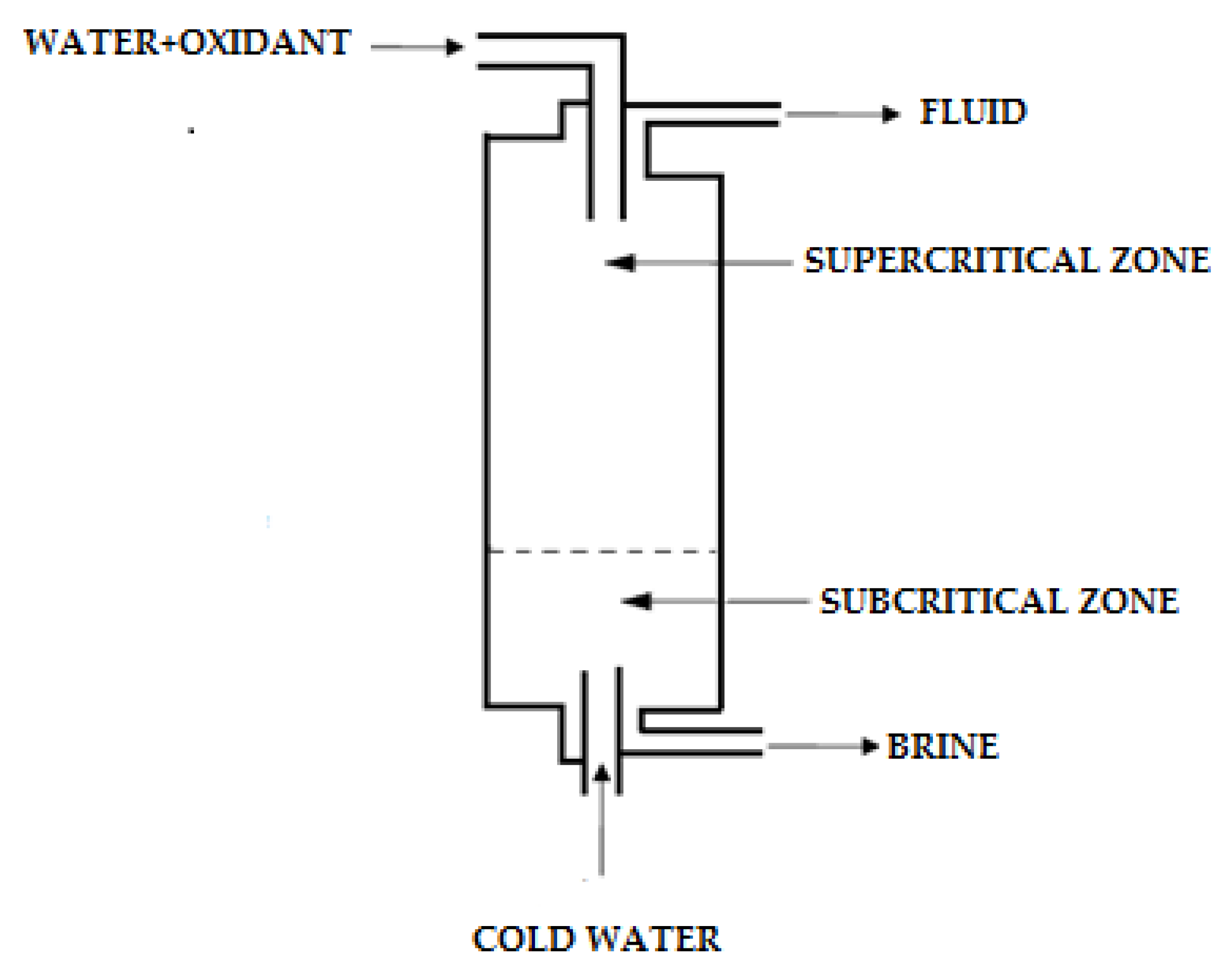
| Modar SCWO tank type reactor [86] | Figure 9 |
|
|
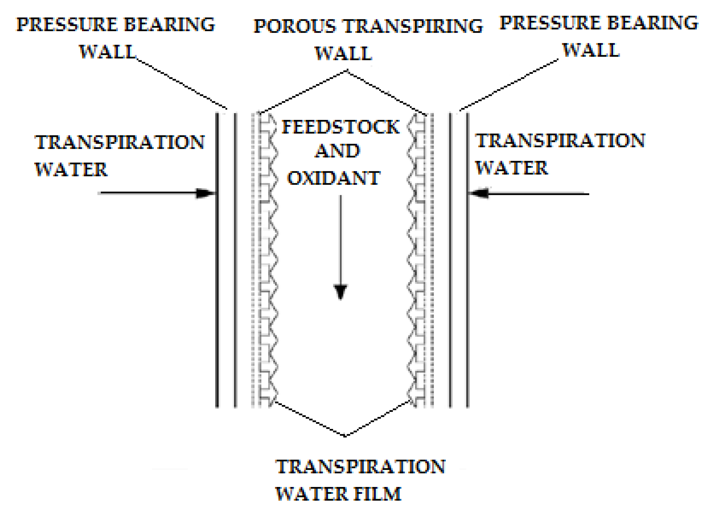
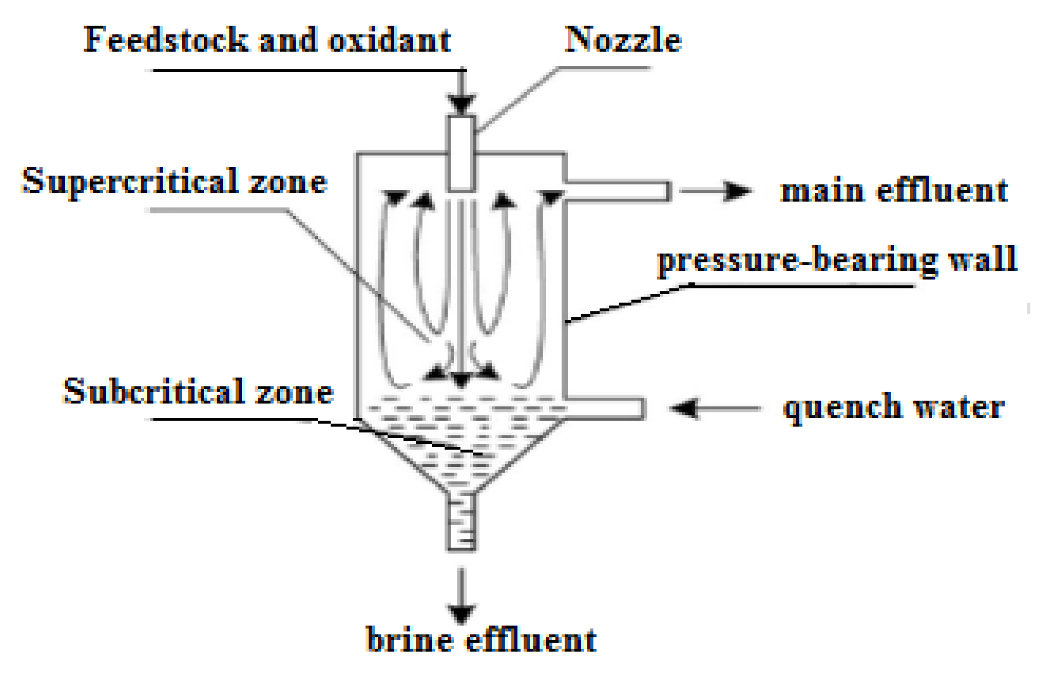
| Transpiring Wall Reactor (TWR) [36] | Figure 10 |
|
|
| Tubular Chematur type reactor [85] | Figure 11 |
|
|
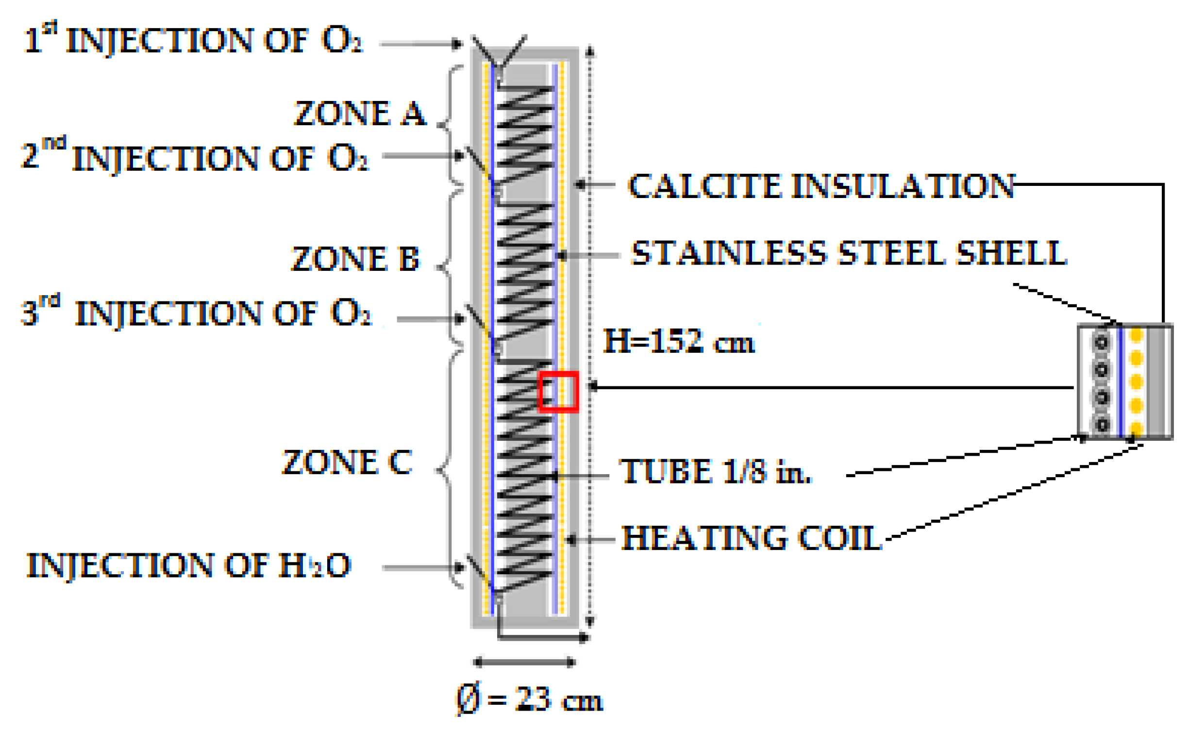
| Vertical multi-injection reactor [87] | Figure 12 |
| |
| Cooled-wall reactor [52] | Figure 13 |
|
|
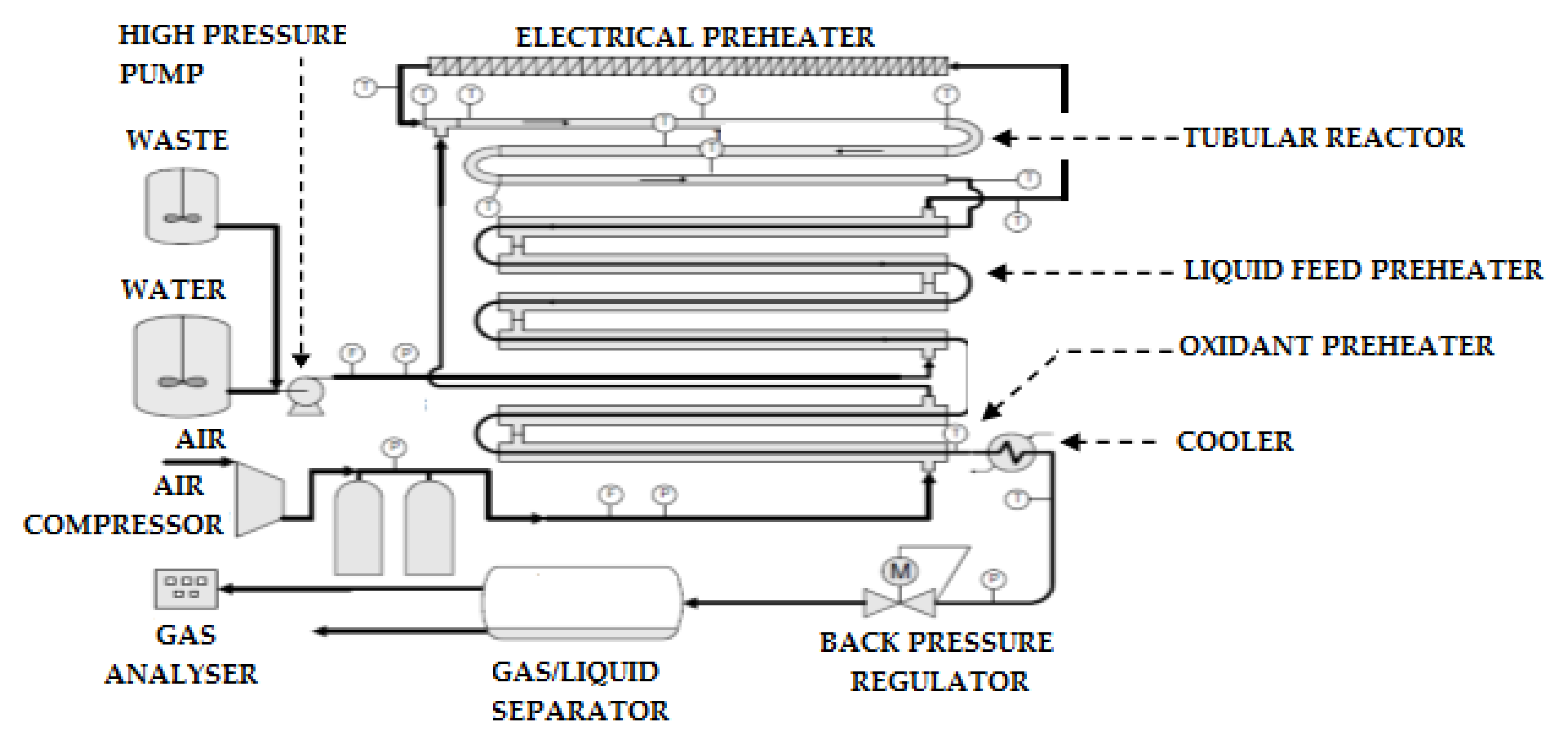
| Cadiz SCWO pilot scale reactor [66] | Figure 14 |
|
|
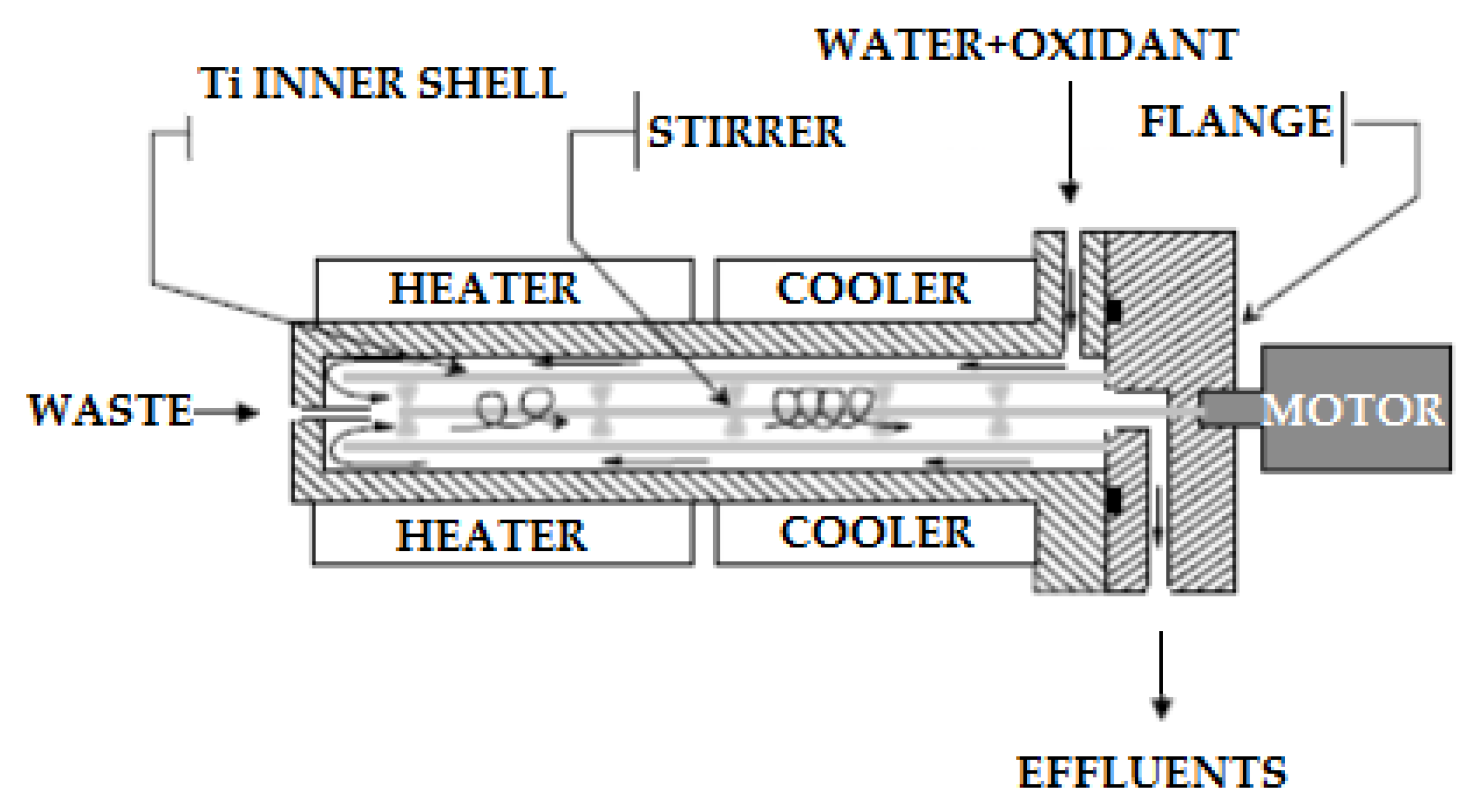
| A double shell reactor [68] | Figure 15 |
|
|
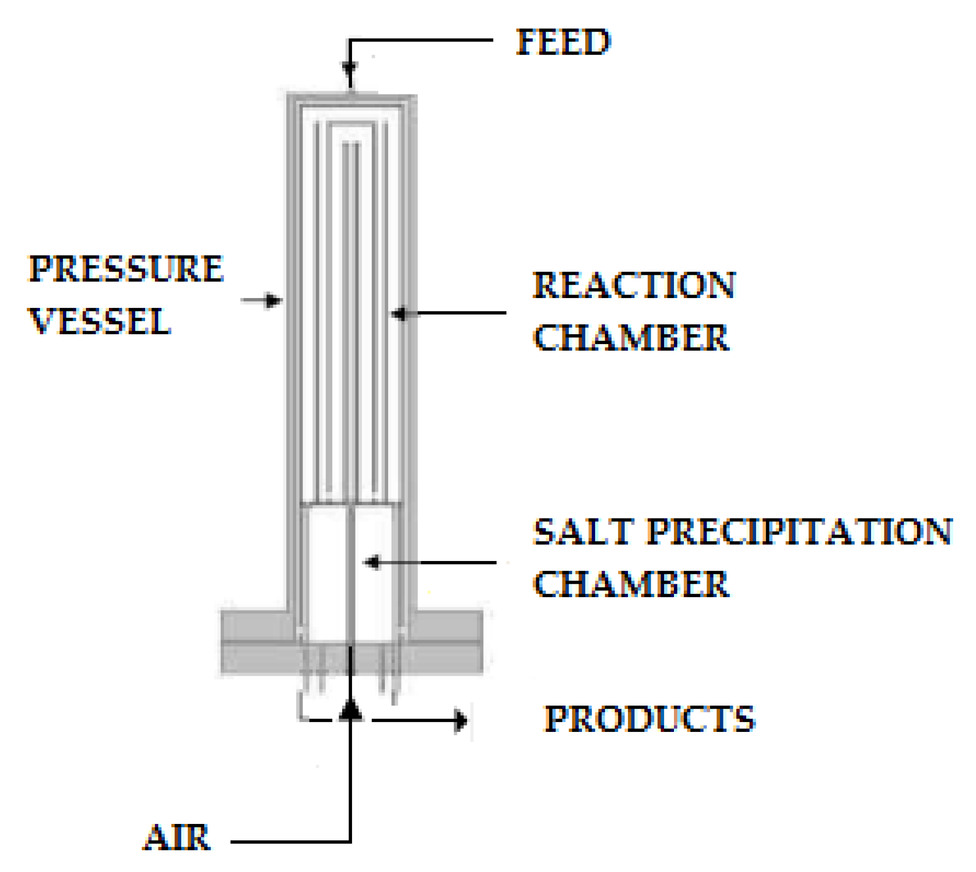
| Reverse flow tank reactor [90] | Figure 16 |
|
|
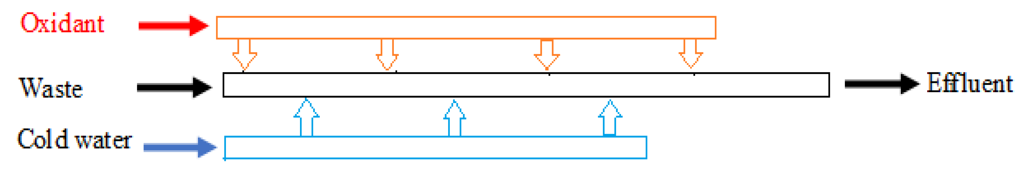
| ‘Y’ shape reactor [91] | Figure 17 |
|
|
| T (°C) | T (MPa) | Mass Flux (kg/m2·s) | Heat Flux (MW/m2) | Correlation |
|---|---|---|---|---|
| 282–527 | 22.6–27.5 | 651–3662 | 0.31–3.46 | |
| 75–576 | 22.8–41.4 | 542–2150 | / | |
| / | / | / | / | |
| / | 23–30 | 600–1200 | 0.1–0.6 | |
| 20–406 | 24 | 200–1500 | 0.07–1.25 |
| Process | Operating Conditions | Corrosion Agent | Max Corrosion Rate mm/yr |
|---|---|---|---|
| Oxidative destruction of chlorocarbons by hydrothermal processing at reasonably high concentrations in a corrosion resistant titanium reactor [106] | 200–500 °C, 600 bar | Hydrogen Chloride, Oxidant, Salt | <0.038 |
| Stainless steel 316 circulation reactor for the oxidation of SW [85] | 375 °C, 380–400 bar | 3% H2O2 solutions | 0.003175 |
| Alloy 625 reactor [111] | 330–550 °C, 400 bar | 2.3% HCl/H2SO4 solutions Salts, oxidant Salts, oxidant | 5.08 |
| Hastelloy C276 reactor [111] | 330–550 °C, 400 bar | 2.3% HCl/H2SO4 solutions Salts, oxidant | 5.08 |
Disclaimer/Publisher’s Note: The statements, opinions and data contained in all publications are solely those of the individual author(s) and contributor(s) and not of MDPI and/or the editor(s). MDPI and/or the editor(s) disclaim responsibility for any injury to people or property resulting from any ideas, methods, instructions or products referred to in the content. |
© 2023 by the authors. Licensee MDPI, Basel, Switzerland. This article is an open access article distributed under the terms and conditions of the Creative Commons Attribution (CC BY) license (https://creativecommons.org/licenses/by/4.0/).
Share and Cite
Benmakhlouf, N.; Outili, N.; García-Jarana, B.; Sánchez-Oneto, J.; Portela, J.R.; Jeguirim, M.; Meniai, A.-H. Applications of Supercritical Water in Waste Treatment and Valorization: A Review. Energies 2023, 16, 2081. https://doi.org/10.3390/en16042081
Benmakhlouf N, Outili N, García-Jarana B, Sánchez-Oneto J, Portela JR, Jeguirim M, Meniai A-H. Applications of Supercritical Water in Waste Treatment and Valorization: A Review. Energies. 2023; 16(4):2081. https://doi.org/10.3390/en16042081
Chicago/Turabian StyleBenmakhlouf, Nadjiba, Nawel Outili, Belén García-Jarana, Jezabel Sánchez-Oneto, Juan R. Portela, Mejdi Jeguirim, and Abdeslam-Hassen Meniai. 2023. "Applications of Supercritical Water in Waste Treatment and Valorization: A Review" Energies 16, no. 4: 2081. https://doi.org/10.3390/en16042081
APA StyleBenmakhlouf, N., Outili, N., García-Jarana, B., Sánchez-Oneto, J., Portela, J. R., Jeguirim, M., & Meniai, A.-H. (2023). Applications of Supercritical Water in Waste Treatment and Valorization: A Review. Energies, 16(4), 2081. https://doi.org/10.3390/en16042081