Article

The Collaborative Optimization of the Discharge Pressure and Heat Recovery Rate in a Transcritical CO2 Heat Pump Used in Extremely Low Temperature Environment

1
Collage of Locomotive and Rolling Stock Engineering, Dalian Jiaotong University, Dalian 116024, China
2
School of Energy and Power Engineering, Xi’an Jiaotong University, Xi’an 710049, China
*
Author to whom correspondence should be addressed.
Energies 2023, 16(4), 2059; https://doi.org/10.3390/en16042059
Submission received: 31 December 2022 / Revised: 10 February 2023 / Accepted: 13 February 2023 / Published: 20 February 2023
(This article belongs to the Special Issue Current Status on the Thermal Management of Electric Vehicles)

Abstract

:
Considering the excellent environmental properties and heating capability under wide running conditions of the natural fluid CO2, the transcritical CO2 heat pump system has widely been used in the application of water heaters, commercial heating and cooling, electric vehicle thermal management, etc. Since the performance was highly affected by the discharge pressure and heat recovery rate in a transcritical CO2 system, the collaborative optimization of these two parameters was analyzed in detail in this study. The results showed that the optimal value of the system heating COP, which was the ration of heating capacity to power consumption, was better under a higher heat recovery rate and relatively lower discharge pressure, which is why these kinds of operating conditions are highly recommended from the perspective of collaborative optimization. Additionally, the heat recovery rate had a positive effect on the system performance when the discharge pressure was lower than its optimal value, while the heat recovery rate would present a passive effect on the system performance when the discharge pressure was higher than its optimal value. The relevant conclusions of this study provide a good theoretical basis for the efficient and stable operation of the transcritical CO2 heat pump technology under the conditions of a wide ambient temperature range.

1. Introduction

Energy security and environmental protection are important factors that affect economic development and daily life. The current global energy structure relies heavily on fossil energy, the increasing consumption of which will not only affect energy security, but also cause huge pollution to the environment. As a major component of energy consumption, the improvement in the structure of industrial, commercial, and residential heating is crucial to energy reform and environmental improvement; thus, heat pump technology has been considered as one of the most promising methods.
Compared with other commonly used refrigerants, CO2 has a GWP of 1 and an ODP of 0, which is beneficial to the environment and can solve the problem of excess global carbon emissions to a large extent. In addition, under extreme operating conditions, carbon dioxide can take advantage of benefits not available in other refrigerants. From the current research and use of CO2 as a working medium, a large number of research findings have proven the superiority of CO2. Xu et al. found that CO2 also has good potential in more extremely cold environments [1]. J. Stene et al. studied a CO2 residential heat pump and further explored the advantages and potential of CO2 in a residential heat pump [2]. Song et al. also studied the optimal temperature and pressure in a CO2 heating system, and their research on CO2 reached below—20 °C, verifying the good performance of CO2 at ultra-low temperature, which is not available in other general refrigerants [3,4]. Due to the great environmentally friendly characteristics as a natural refrigerant and its superior heating capacity under low-temperature, carbon dioxide has become the best choice for the working medium in heat pump technology [5]. CO2 has many advantages to be explored, but it does have some inevitable disadvantages. Rhoy et al. studied the refrigeration performance of a CO2 working medium and believe that its refrigeration capacity needs to be improved [6].
As one of the important branches of refrigeration technology, researchers have carried out a lot of investigations into trans-critical CO2 technology. Mamdouh et al. found that geothermal energy and CO2 combined power plant produced more power and had better efficiencies [7]. The development of a trans-critical CO2 heat pump water heater technology is relatively mature, with more and more studies being published. As early as when the transcritical CO2 unit was proposed by Lorentzen et al. [8], the existence of the optimal discharge pressure was determined, which had a major impact on both the capacity and efficiency. Correlations based on theoretical analysis for the determination of the optimal discharge pressure in terms of several system parameters were then proposed for the efficient control of transcritical CO2 units [9,10,11,12]. Apart from the gas-cooler outlet temperature, the evaporating temperature is another common decisive parameter. The optimal discharge pressure increases with the augmentation of the evaporating temperature and the gas-cooler outlet temperature in all correlations. However, significant deviations higher than 10% were found to exist between the correlation results and the actual experimental optimal discharge pressure [13,14], indicating that more detailed investigation of the optimal discharge pressure should be carried out based on the specific structure of the transcritical CO2 plant.
Despite the simple structure and low cost, the implementation of an internal heat exchanger (IHX) is widely acknowledged and has been proven to be efficient. Nguyen et al. [15] carried out a 4-month long-term simulation to verify the advantages of a direct expansion CO2 ground source heat pump using an IHX. The simulation considered changes in the ground surface temperature and proved that the IHX could alleviate thermal short circuits, resulting in a 22% higher COP than a system without an IHX. Apera et al. [16] analyzed the CO2 and R134a refrigeration system based on experimental data according to the second law of thermodynamics, and the results showed that the exergy efficiency of the CO2 cycle could be improved by using an IHX. Wang et al. [17] compared four different transcritical CO2 refrigeration cycles through the simulation method, and the simulation results showed that the IHX is beneficial to the improvement in the energy efficiency of the CO2 cycle, especially when the discharge pressure is lower than the optimal pressure. Chen et al. [9] studied the influence of the IHX on the optimal discharge pressure, and the results indicate that the optimal discharge pressure would decrease.
The disadvantages brought by the IHX to the transcritical CO2 system were also investigated. Ituna et al. [18] established a CFD model to study the thermophysical properties of CO2 in the IHX in detail, and analyzed the influence of different boundary conditions on the heat transfer, mainly the mass flow rate of the hot and cold side fluids. It was found that the system COP was inversely proportional to the heat recovery rate and the COP increased from 2 to 2.55 as the heat recovery rate decreased from 0.85 to 0.35. Cao et al. [19] theoretically studied the effect of the IHX size on a transcritical CO2 heat pump at different ambient temperatures. The authors adopted a tube-in-tube heat exchanger as the IHX, and the results showed that the increase in length of the regenerator was always beneficial to the increase in COP. However, the exorbitant discharge temperature and the decreasing capacity would limit the length of the IHX. Luger et al. [20] proposed a multi-objective design optimization for a transcritical CO2 cycle, and the IHX was included as one of the optimization objectives.
It can be concluded from the literature available that the application of an IHX should also be optimized under realistic conditions. As the most common implementation of improving the transcritical CO2 cycle, the optimization of an IHX under different conditions would be of great benefit. In addition, the co-optimization of the discharge pressure should also be taken into consideration. However, few studies have been found available concerning this co-optimization of both the heat recovery rate and the discharge pressure. In this paper, we established a co-optimization model of a transcritical CO2 heat pump water heater in AMESim. A bypass-valve was adopted to regulate the heat recovery rate and an EEV was used to control the discharge pressure. The co-optimization of the heat recovery rate and the discharge pressure was conducted under various conditions.

2. The Establishment of the Simulation Model

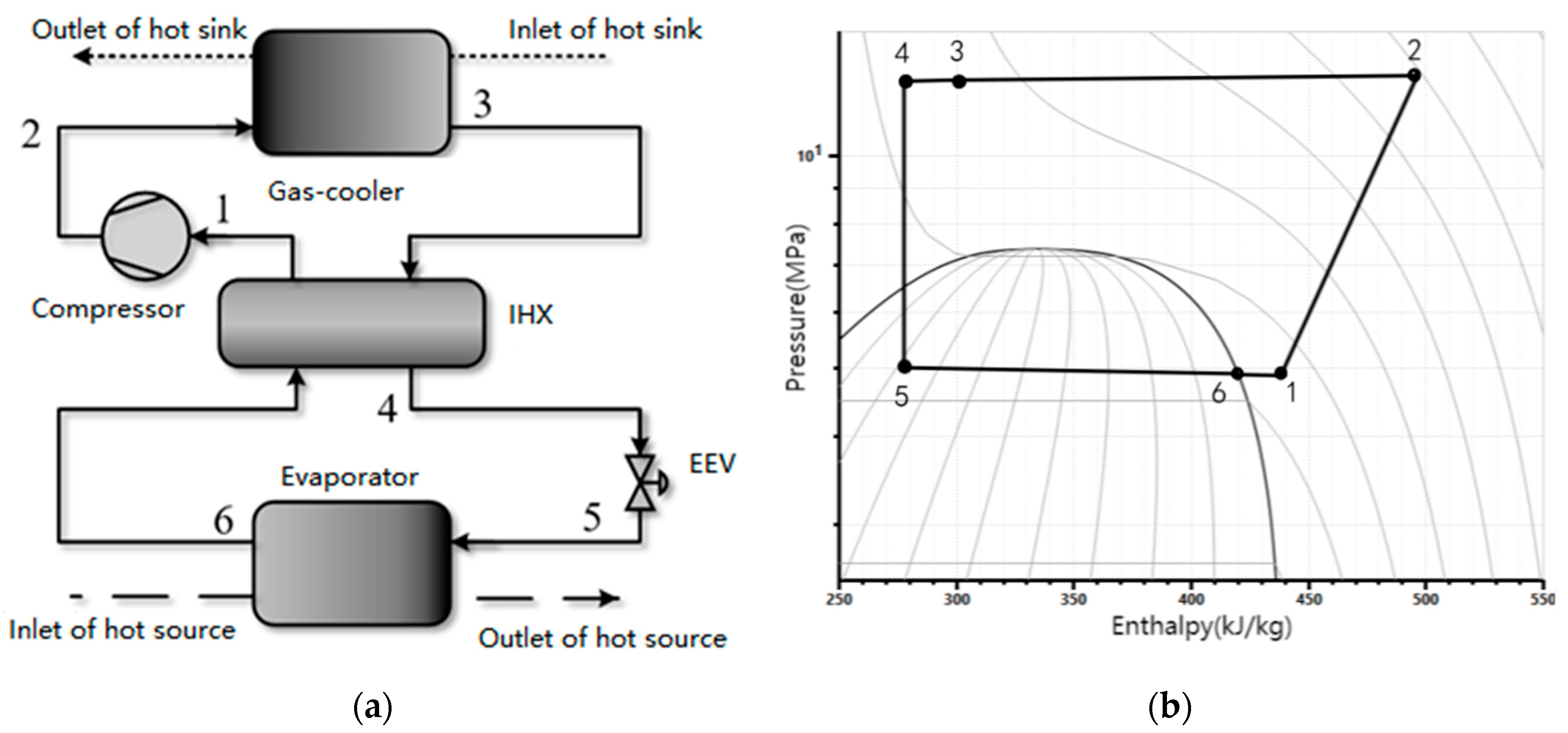
2.1. The Transcritical CO2 Thermal Management System

Figure 1a shows a schematic of a transcritical CO2 thermal management system. The transcritical CO2 unit mainly consists of a compressor, a tube-in-tube gas-cooler, a tube-in-tube IHX, an EEV, and a fin-and-tube evaporator. The refrigerant absorbs heat from the air in the evaporator and releases heat to the return water in the gas-cooler.
The detailed change in the thermodynamic properties of the refrigerant can be explained in the following process:
1–2: Adiabatic and non-isentropic compression process in the compressor;
2–3: Heat rejection process to water in the gas-cooler;
3–4 and 6–1: Heat exchange process in the IHX;
4–5: Isenthalpic throttling process in the expansion valve;
5–6: Heat absorption process from the air in the evaporator.

2.2. The Simulation Model

The simulation model of the transcritical CO2 thermal management system was built via AMESim. As shown in Figure 2, the main components including the compressor, the gas-cooler, the expansion valve, the evaporator, and the separator are connected as per the schematic in Figure 1a.

2.2.1. Compressor Model

Under the given conditions of the high pressure and inlet thermodynamic state, the compressor model calculates the mass flow rate and the outlet thermodynamic state, according to the following equations:
m ˙ = ρ s N V d i s η v
h d = h s + h d i s h s η i s
P = m ˙ ( h d h s ) η m
η v = 1.19379 0.13635 P d P s
η m = 0.64107 + 0.07487 P d P s
η s = 0.8014 0.04842 P d P s
where N and V d i s are the speed and displacement of the compressor; ρ s and h s are the density and enthalpy of the suction state; h d i s is the enthalpy value of discharge port after isentropic compression; P is the power consumption of the compressor; η v , η i s , and η m are the volume efficiency, isentropic efficiency, and mechanical efficiency of the compressor, respectively, which are commonly the functions of the pressure ratio.

2.2.2. Gas-Cooler Model and IHX Model

The tube-and-tube heat exchanger model was adopted for both the gas-cooler and the IHX. The heat exchange in each element of the tube-and-tube heat exchanger are calculated according to the following equations:
Q ˙ h x = j = 1 N K j A i , j ( T h o t T c o l d )
K j = ( 1 i n s i d e , j + A i , j o u t s i d e , j A o . j + R W , j ) 1
where i n s i d e , j and o u t s i d e , j are the local heat transfer coefficients of the inner and outer sides of the tube-and-tube heat exchanger. The local heat transfer coefficient of CO2 can be calculated using the correlations proposed by Dang and Hihara [21,22]:
r = N u r λ b d i . i
N u r = ( f r / 8 ) ( R e b 1000 ) P r 1.07 + 12.7 f r / 8 ( P r 2 / 3 1 )
where N u r is the Nusselt number of CO2 in the heat exchanger tube; λ b is the thermal coefficient of CO2 in the temperature inside the tube; d i . i is the diameter of the inner tube of the heat exchanger tube; f r is the friction coefficient of CO2 in the heat exchange tube; R e b is the Reynolds number of the temperature inside the tube; Pr is the Prandtl number in the heat exchanger tube. The equations of f r , R e b , and Pr are detailed in the reference.
The water side heat transfer coefficient is calculated by the Dittus–Boelter equation:
w = N u w λ w D e q
N u w = 0.023 R e w 0.8 P r w 0.4
R e w = u w D e q ν w
P r w = C p w μ w λ w
where N u w is the Nusselt number of water; λ w is the thermal coefficient of water; R e w is the Reynolds number of water; P r w is the Prandtl number of water; u w is the speed of water; D e q is the equivalent diameter of the outer tube of the tube heat exchanger; ν w is the kinematic viscosity of water; C p w is the specific heat capacity at constant pressure of water; μ w is the dynamic viscosity of water.

2.2.3. Evaporator Model

The fin-and-tube heat exchanger was adopted for the evaporator. The energy balance equations for the CO2 and air sides are expressed by:
Q ˙ e v a = m ˙ C O 2 ( h C O 2 , o u t h C O 2 , i n ) = m ˙ a i r ( h a i r , i n h a i r , o u t )
Q ˙ e v a = j = 1 N K j A i , j ( T C O 2 , j T a i r , j )
K j = ( 1 C O 2 , j + R j + A i , j a i r , j ε η 0 A o , j ) 1
where Q ˙ e v a is the heat exchange capacity in the evaporator; m ˙ C O 2 and m ˙ a i r are the mass flow rate of CO2 and air, respectively; h C O 2 , o u t , h C O 2 , i n , h a i r , i n , h a i r , o u t are the outlet enthalpy of CO2, inlet enthalpy of CO2, inlet enthalpy of air, outlet enthalpy of air, respectively; T C O 2 , j and T a i r , j are the temperature of CO2 and air in a section of the evaporator; η 0 is the total efficiency of rib surface; A o , j is the sum of fin and root area; ε is the moisture separation coefficient; K j is the overall heat transfer coefficient, where the local transfer coefficient C O 2 , j during the evaporating process was calculated by the correlation proposed by Cheng et al. [23]:
I o r A = w e t = [ ( S n b ) 3 + c b 3 ] 1 / 3
n b = 131 p r 0.0063 ( log 10 p r ) 0.55 M 0.5 q 0.58
S = { 1 , w h e n   x < x I A ,   i n t e r m i t t e n t   f l o w 1 1.14 ( D e q 0.00753 ) 2 ( 1 δ δ I A ) ,   w h e n   x x I A ,   a n n u a l   f l o w
c b = 0.0133 R e δ 0.69 P r L 0.4 λ L δ
where I o r A is the heat transfer coefficient of CO2 in annular or intermittent flow regimes; w e t is the heat transfer of the wet circumference of the heat exchanger tube; S is the limiting factor of the nucleate boiling heat transfer coefficient; n b is the heat transfer coefficient of nucleate boiling; c b is the heat transfer coefficient of convection boiling; p r is the contrast pressure; M is the molecular weight of CO2; R e δ is the Reynolds number of liquid film; P r L is the Prandt number of liquid film; λ L is the thermal coefficient of liquid CO2; δ is the liquid film thickness. The equations of R e δ , δ and p r are detailed in the reference.

2.2.4. Design Specifications

Apart from the model information clarified above regarding the compressor and heat exchangers, more detailed information of the design specifications of the gas-cooler, the evaporator, the IHX, and the separator are provided in Table 1.

2.2.5. Parameters Used in the Analysis

The refrigerant circuit was cycled in the order shown in Table 2, and the parameters were input and output in the order accordingly.

2.3. Methodology

The co-optimization of the discharge pressure and the heat recovery rate was conducted based on the evaluation of the system COP:
C O P = Q ˙ P
where P is the power consumption of the whole system; Q ˙ is the heating capacity calculated by the mass flow rate m ˙ w , specific heat capacity at constant pressure C p , the inlet water temperature T w , i n , and outlet water temperature T w , o u t :
Q ˙ = m ˙ w C p ( T w , o u t T w , i n )
The heat recovery rate is defined by the ratio of the realistic temperature increase to the theoretical maximum temperature increase of the low-pressure side:
ε = T 1 T 6 T 1 , m T 6
where T 1 is the suction temperature; T 6 is the evaporator outlet temperature; and T 1 , m is the theoretical maximum suction temperature, which is the outlet temperature of the gas-cooler.
In the transcritical CO2 thermal management system, a bypass-valve was adopted to adjust the heat recovery rate and the discharge pressure was regulated by the opening of the expansion valve. The system performance was optimized in terms of both the discharge pressure and the heat recovery rate. Although the water supply temperature highly affects the optimal discharge pressure value of the transcritical CO2 system, we used a fixed water supply temperature of 60 °C that could be heated by a gas-cooler.

3. Results and Discussion

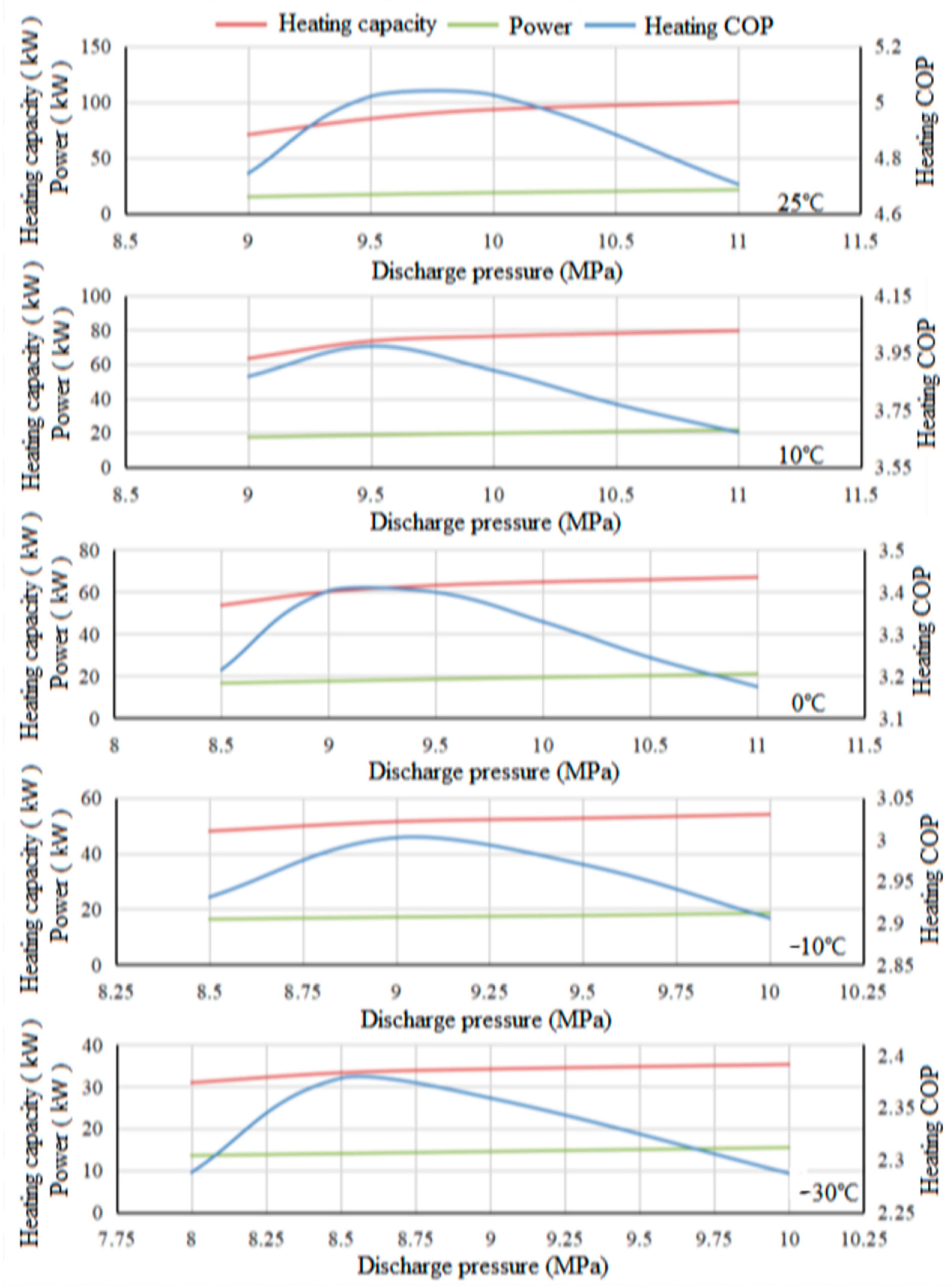
3.1. The Thermodynamic Characteristics with the Discharge Pressure

As is well-known to all, the discharge pressure has always been one of the most significant parameters in a transcritical CO2 system including the transcritical CO2 heat pump discussed in this research. Based on the AMESim theoretical models presented in Section 2.3, the operating parameters of the transcritical CO2 heat pump in any steady state could be obtained under certain operating conditions. The most important macro indicator of the transcritical CO2 heat pump cycle such as the heating capacity, power consumption, and heating COP are clearly shown in Figure 3 with the increase in the discharge pressure.
It can be seen from Figure 3 that the heating capacity of the transcritical CO2 heat pump rose gradually as the discharge pressure increased, while the ascending gradient changed slightly. For instance, under 25 °C, 10 °C, and 0 °C in ambient temperature, the ascending gradients of the heating capacity were higher in the beginning, but became lower during the second half of the research range. However, the ascending gradients of the heating capacity were not that visible under lower ambient temperatures such as the situations under −10 °C and −30 °C in ambient temperature. That is, considering the isotherm trends of the CO2 P-h diagram as shown in Figure 1b, a higher heating enthalpy difference will always be caused because the state point of the gas-cooler outlet would definitely move left when the discharge pressure becomes higher.
Additionally, in contrast to the heating capacity, the power consumption of the transcritical CO2 compressor increased slightly and gradually as the discharge pressure rose, regardless of the ambient temperature. It can be seen from Figure 1b that the isotherm trends were almost parallel in the superheated region, which was the reason for the linearly ascending power consumption with the increase in the discharge pressure.
As the result of the heating capacity (which increased rapidly and then slowly) and the power consumption (that increased linearly), the heating COP of the transcritical CO2 heat pump system always presented the same trend across the whole research range. That is, the heating COP of the transcritical CO2 heat pump system increased first and then decreased with the rising discharge pressure, and the absolute value of the change gradient during the decreasing period was almost lower than that during the increasing period, as shown in all the diagrams in Figure 3.
Additionally, it was obvious that the main performances of the transcritical CO2 heat pump system were remarkably affected by the ambient temperature, for instance, the heating COP, heating capacity, power consumption, and the optimal value of the discharge pressure decreased significantly with the decline in ambient temperature. The maximum value of the heating COP reduced from more than 5.0 to almost 2.35 and the maximum value of the heating capacity reduced from almost 100 kW to 35 kW, with the ambient temperature declining from 25 °C to −30 °C. Furthermore, the optimal values of the discharge pressure would be observed at 9.7 MPa, 9.5 MPa, 9.2 MPa, 9 MPa, and 8.6 MPa under 25 °C, 10 °C, 0 °C, −10 °C, and −30 °C in the ambient temperatures, respectively. Because it would be more and more difficult for the transcritical CO2 heat pump system to absorb heat from the atmospheric environment with the decline in ambient temperature, a significant deterioration of the system performance above-mentioned could finally be obtained.

3.2. The Thermodynamic Characteristics with the Heat Recovery Rate

Except for the optimal discharge pressure mentioned in Section 3.1, another significant optimizable property in the transcritical CO2 heat pump system was the heat recovery rate between the refrigerant in the gas-cooler outlet and the suction line. By recovering the heat energy, the refrigerant temperature at the gas-cooler outlet could be further cooled down by the refrigerant at the suction line with lower temperature, while the heating and cooling enthalpy difference could also be visibly enhanced. However, since the refrigerant temperature at the suction line was heated up to a higher value, the discharge temperature of the compressor might exceed the limit (higher than 150 °C) under the operating condition with high pressure ratio (that often occurs under the running condition with low ambient temperature). Additionally, excessive suction superheating degree in the transcritical CO2 heat pump system would cause the decreasing suction density, thereafter the decreasing mass flow rate in the heat pump system, thus, the heating capacity would generally decline, even if the heating enthalpy difference increased.
To sum up, it must enhance the system performance (including the heating capacity and COP) of the transcritical CO2 heat pump to provide an appropriate heat recovery rate, while the performance might be attenuated when the heat recovery rate is too high. In order to quantitatively judge the effect of the heat recovery rate on the system performance of the transcritical CO2 heat pump discussed in this study, a detailed study with plentiful results was carefully carried out, and the sketch map of the optimal heat recovery rate in the transcritical CO2 system is clearly shown in Figure 4.
First, it was observed that the effects of the heat recovery rate on the system performance were slight, where the impact was generally less than 10%. The heating COP of the transcritical CO2 heat pump system was dramatically affected by the ambient temperature, which was already analyzed in Section 3.1, and the exact value of the heating COP was reduced from more than 5.0 (under 25 °C in ambient temperature) to less than 2.5 (under −30 °C in ambient temperature).
Then, under every certain ambient temperature, all of the effects of the heat recovery rate on the system performance of the transcritical CO2 heat pump presented obvious differences, as shown in Figure 4. It can be concluded that under every running condition with different ambient temperatures, the system heating COP would gradually increase with the rise in the heat recovery rate when the discharge pressure was relatively low. However, the system heating COP decreased obviously with the rising heat recovery rate when the discharge pressure was relatively high. Furthermore, as a compromise, the system heating COP increased first and then declined with the rising heat recovery rate when the discharge pressure was taken to an intermediate value.
To sum up, it can be concluded that even the heat recovery rate had a significant influence on the system performance of a transcritical CO2 heat pump. This effect was also highly influenced by the discharge pressure. That is, considering the joint effects on the system performance, the discharge pressure and the heat recovery rate can be treated as a pair of interrelated parameters coupled with each other.
Additionally, it can be inferred that the heat recovery rate had a positive effect on the system performance (that is, the system performance will increase with the rising heat recovery rate) when the discharge pressure was lower than its optimal value while the heat recovery rate would present a passive effect on the system performance (that is, the system performance will decrease with the rising heat recovery rate) when the discharge pressure was higher than its optimal value. Therefore, the global maximum performance of the transcritical CO2 heat pump system must be obtained under the situation when the discharge pressure and heat recovery rate have achieved their optimal values at the same time.

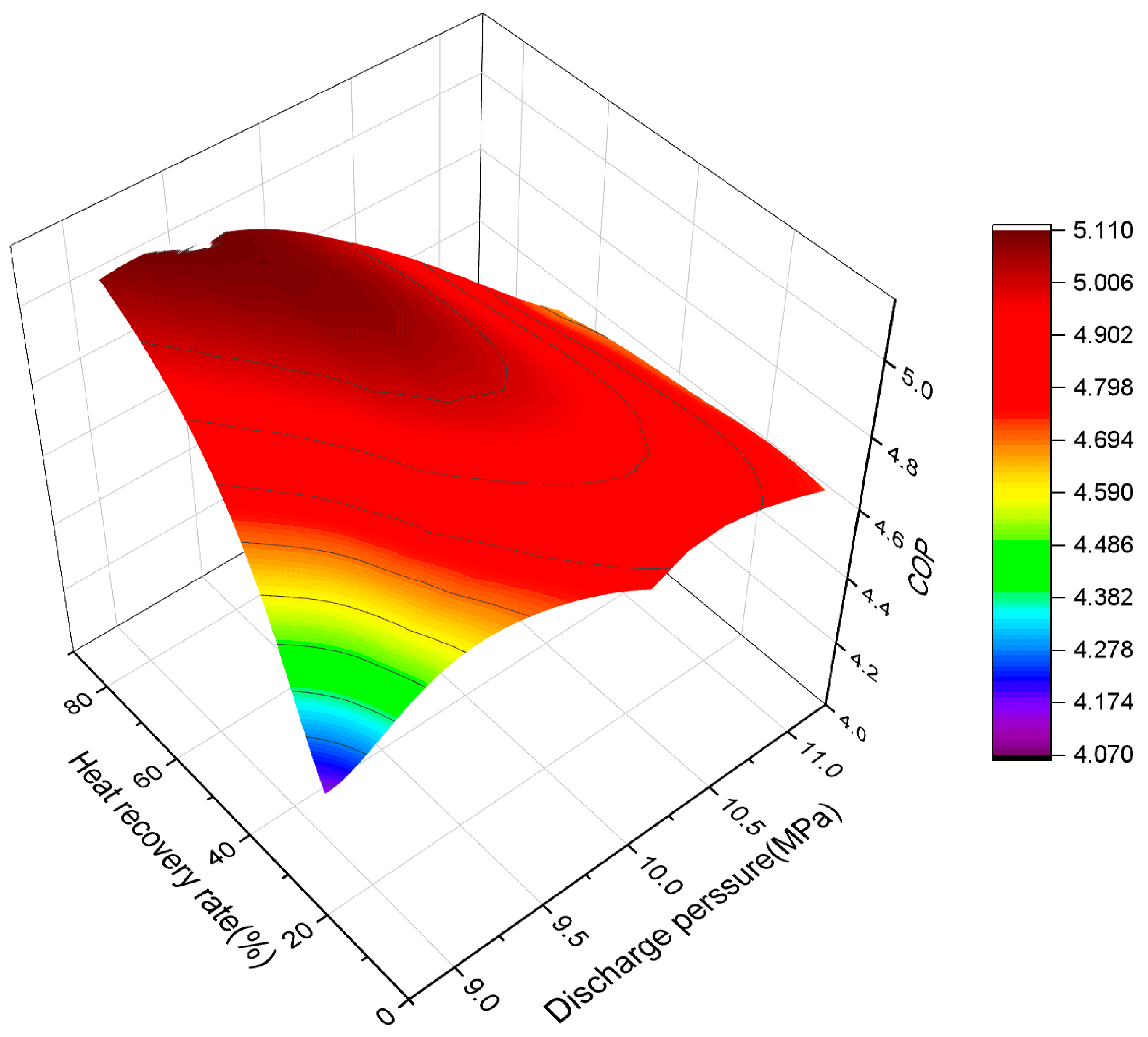
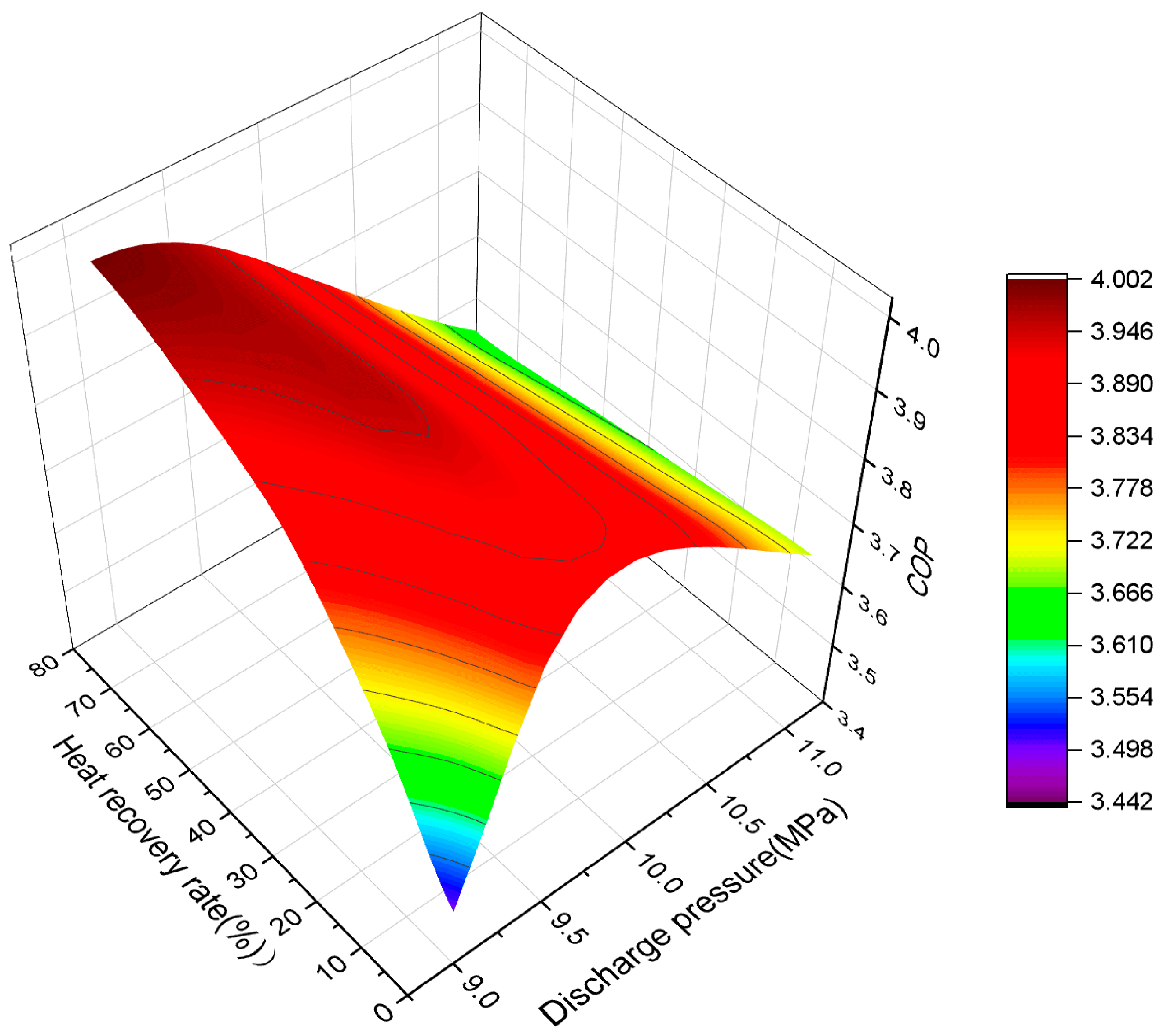
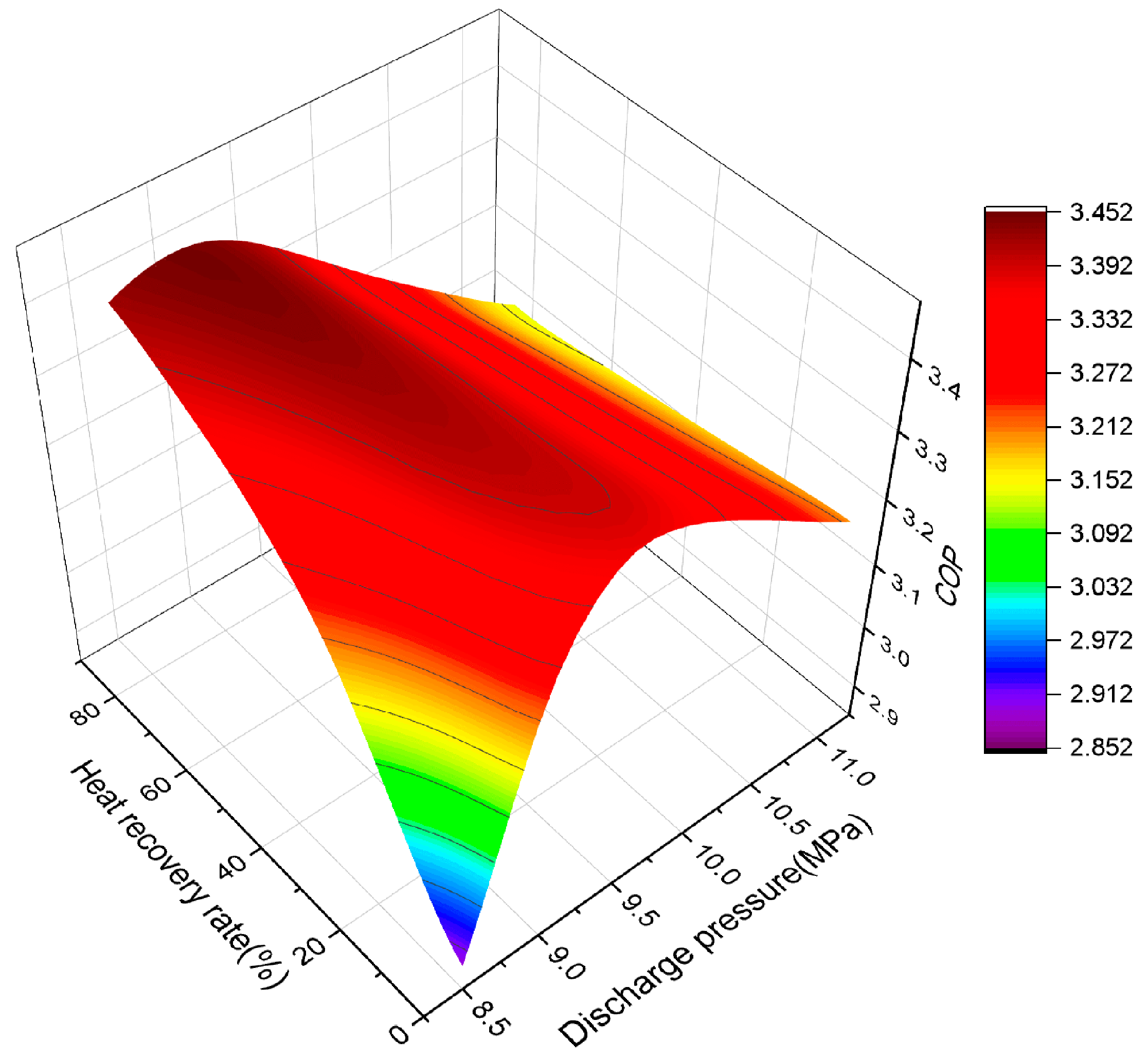
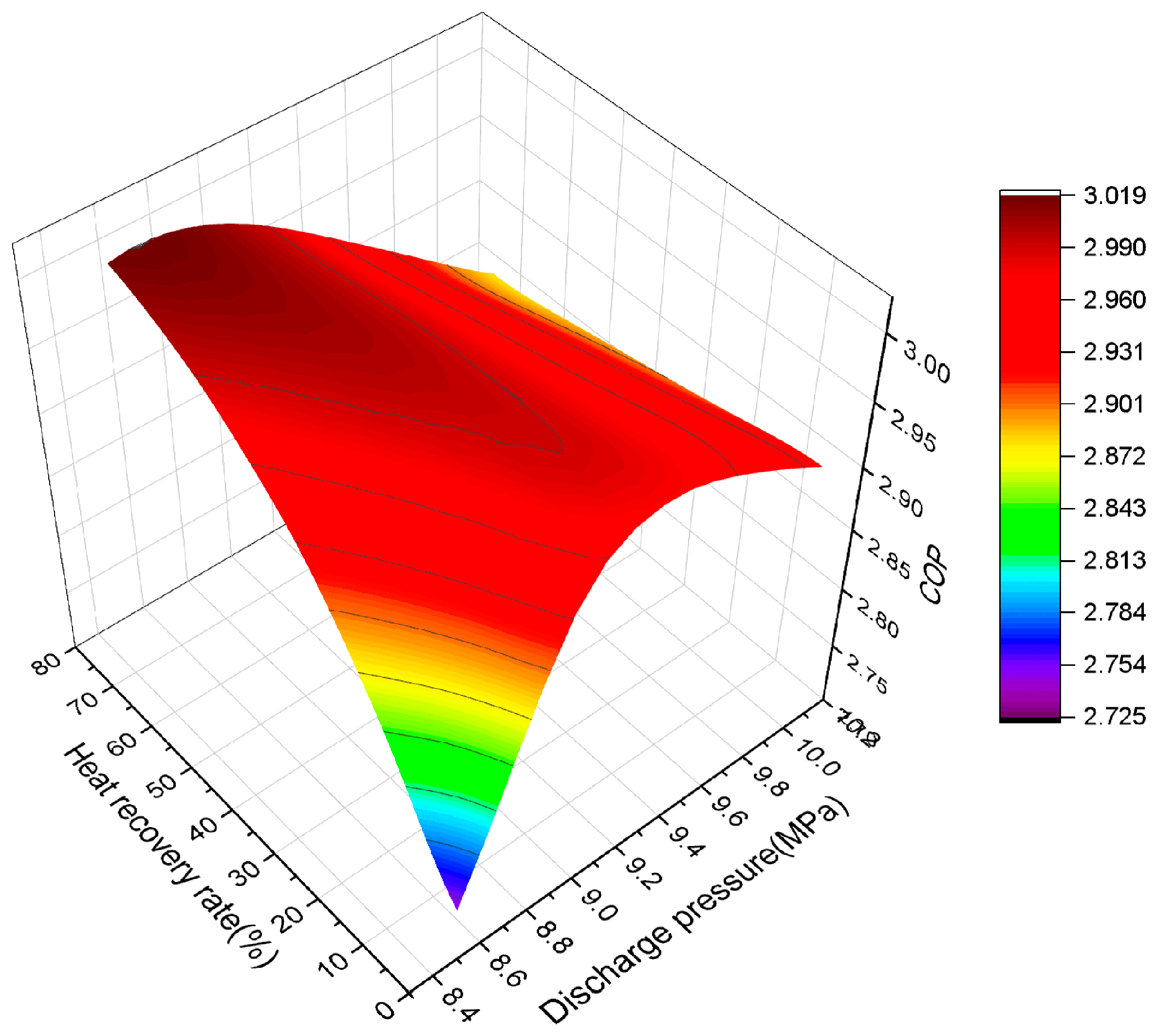
3.3. The Collaborative Optimization of the Discharge Pressure and Heat Recovery Rate

As above-mentioned, the discharge pressure and the heat recovery rate should be treated as a pair of interrelated parameters coupled to each other, thus, the quantitative analysis of the collaborative optimization of the discharge pressure and heat recovery rate is presented in this section.
The system heating COP trends of the transcritical CO2 heat pump are clearly shown in Figure 5, Figure 6, Figure 7, Figure 8 and Figure 9 based on the varying discharge pressure and heat recovery rate under different ambient temperatures. Compared with the heat recovery rate, it can be seen from Figure 5, Figure 6, Figure 7, Figure 8 and Figure 9 that the effects of the discharge pressure on the heat pump system performance were much more visible, however, the deterioration in the heat pump system performance was also significant under the running condition with a very low heat recovery rate. That is, it was quite necessary to set an appropriate heat recovery rate in the transcritical CO2 heat pump system, while the optimal value of the heat recovery rate in the transcritical CO2 heat pump system was relatively vague. Furthermore, it was noticed that the general trend in the optimal heat recovery rate is that the higher the heat recovery rate in the transcritical CO2 heat pump, the better the system performance.
Additionally, it was remarkable that there must be a strong coupling relationship between the heat recovery rate and the discharge pressure. For instance, the optimal discharge pressure of the system varied with the changing heat recovery rate under the same running condition; it can be observed from Figure 5, Figure 6, Figure 7, Figure 8 and Figure 9 that the optimal value of the discharge pressure will decrease with the rising heat recovery rate, that is, by increasing the heat recovery rate at a certain cost, the discharge pressure can be reduced from another aspect to ensure the safe and stable operation of the transcritical CO2 heat pump system. On the other hand, it could be noted from the general trends that the optimal value of the system heating COP was better under a higher heat recovery rate and relatively lower discharge pressure, which is why these kinds of operating conditions are highly recommended from the perspective of the collaborative optimization of the discharge pressure and heat recovery rate.
Although the effects of the discharge pressure and heat recovery rate on the system performance of the transcritical CO2 heat pump were significant, the degree of the influence was also highly affected by the ambient temperature. For instance, it can be drawn from Figure 5, Figure 6, Figure 7, Figure 8 and Figure 9 that the optimization effect of the collaborative adjustment with the discharge pressure and heat recovery rate was more than 20% among the research range under 25 °C in the ambient temperature, however, the optimization effect has strongly deteriorated to 14%, 17.4%, 9.2%, and 9.7% with 10 °C, 0 °C, −10 °C, −30 °C in the ambient temperature, respectively.
Additionally, it can be seen from Figure 5, Figure 6, Figure 7, Figure 8 and Figure 9 that the effect of the heat recovery rate on the system performance also deteriorated with the gradual decline in the ambient temperature. For instance, under the worst running condition with −30 °C in the ambient temperature, the optimization effects of the heat recovery rate almost disappeared, which indicates that the IHX was no longer that helpful under ultra-low ambient temperature, while different heat recovery rates would not continuously affect the optimal performance of the transcritical CO2 heat pump system, and only slightly affected the value of the optimal discharge pressure. In detail, as usual, the optimal discharge pressure will decrease with the rising heat recovery rate under an ultra-low ambient condition.
Additionally, it can be drawn from Figure 5, Figure 6, Figure 7, Figure 8 and Figure 9 that the worst system heating COP of the transcritical CO2 heat pump was always found under the condition with the lowest discharge pressure and lowest heat recovery rate, which indicated that the decreasing gradient of the system performance after exceeding the optimal values (of both heat recovery rate and discharge pressure) was visibly less than the increasing gradient before reaching the optimal values (of both the heat recovery rate and discharge pressure).
Furthermore, among the simulation domain, it can be seen from Figure 5, Figure 6, Figure 7, Figure 8 and Figure 9 that the sub-low point of the system heating COP could be found under the running condition with the highest discharge pressure and highest heat recovery rate, which demonstrated that blindly increasing the discharge pressure as well as the heat recovery rate was usually adverse to the system performance, and that this attenuation was also very obvious. Furthermore, this phenomenon also indicated the conclusion of Section 3.2, that the heat recovery rate had a positive effect on the system performance when the discharge pressure was lower than its optimal value, while the heat recovery rate would present a passive effect on the system performance when the discharge pressure was higher than its optimal value.

4. Conclusions

Considering the excellent environmental properties and heating capability under wide running conditions of the natural fluid CO2, the transcritical CO2 heat pump water heater system was comprehensively studied with regard to the collaborative optimization of the discharge pressure and heat recovery rate. Based on many theoretical studies, the main conclusions can be drawn as follows:
  • In a typical transcritical CO2 heat pump system, there are two optimizable parameters that affect the system performance significantly, which are the heat recovery rate and the discharge pressure, where higher or lower values of these two parameters will definitely cause a deterioration in the system performance.
  • There is a very complicated coupling relationship between the heat recovery rate and the discharge pressure. The actual values of these two parameters would significantly affect the optimal values of each other, thus, these two optimizable parameters should be optimized collaboratively.
  • The optimal value of the system heating COP was better under a higher heat recovery rate and a relatively lower discharge pressure, which is why these kinds of operating conditions are highly recommended from the perspective of the collaborative optimization of the discharge pressure and heat recovery rate.
  • The heat recovery rate had a positive effect on the system performance when the discharge pressure was lower than its optimal value, while the heat recovery rate presented a passive effect on the system performance when the discharge pressure was higher than its optimal value.

Author Contributions

Z.W.: Conceptualization, Methodology, Writing, Reviewing and Editing; F.B.: Data Collection, Reviewing and Editing; J.F.: Data Collection, Reviewing and Editing; Z.Z.: Modelling, Reviewing; Y.S.: Conceptualization and Supervision; F.C.: Conceptualization and Supervision. All authors have read and agreed to the published version of the manuscript.

Funding

This research was funded by the National Natural Science Foundations of China (52006161).

Data Availability Statement

Data unavailable due to privacy restrictions.

Conflicts of Interest

The authors declare no conflict of interest.

Nomenclature

AHeat transfer area (m2)vVolumetric
VVolume (m3)disDisplacement
NRotary speed (rev∙min−1)sSuction
hEnthalpy (kJ∙kg−1)isIsentropic
KHeat transfer coefficient (W∙K−1∙m−2)mMechanical
m ˙ Mass flow rate (kg∙s−1)dDischarge
PPower consumption (J)hxHeat exchanger
Heat transfer coefficients (W∙K−1∙m−2)evaEvaporate
TTemperature (°C)wWater
Q ˙ Quantity of heat (W)iInside
ρ Density (kg∙m−3)jParameter at cell level
η EfficiencyWWall
ReReynolds numberpPressure
NuNusselt numberrRefrigerant
PrPrandtl numbereqEquivalent
MMolecular weight (kg·kmol−1)LLiquid
ε Moisture separation coefficient///Heat recovery ratenbNucleate boiling
Slimiting factor of nucleate boiling heat transfer coefficientcbConvection boiling
λ Thermal coefficient (kW·(K·m)−1) δ Liquid film thickness
D/dDiameter(m)oOutside
δ Liquid film thickness (m)

References

  1. Xu, Y.; Mao, C.; Huang, Y.; Shen, X.; Xu, X.; Chen, G. Performance evaluation and multi-objective optimization of a low-temperature CO2 heat pump water heater based on artificial neural network and new economic analysis. Energy 2021, 216, 119232. [Google Scholar] [CrossRef]
  2. Stene, J. CO2 Heat pump system for space heating and hot water heating in low-energy houses and passive houses. In Proceedings of the 1st Nordic Passive House Conference Passivhus Norden, Trondheim, Norway, 2–3 April 2008; Volume 36. [Google Scholar]
  3. Song, Y.; Cui, C.; Li, M.; Cao, F. Investigation on the effects of the optimal medium-temperature on the system performance in a transcritical CO2 system with a dedicated transcritical CO2 subcooler. Appl. Therm. Eng. 2020, 168, 114846. [Google Scholar] [CrossRef]
  4. Song, Y.; Ye, Z.; Wang, Y.; Cao, F. The experimental verification on the optimal discharge pressure in a subcooler-based transcritical CO2 system for space heating. Energy Build 2018, 158, 1442–1449. [Google Scholar] [CrossRef]
  5. Cao, F.; Song, Y.; Li, M. Review on development of air source transcritical CO2 heat pump systems using direct-heated type and recirculating-heated type. Int. J. Refrig. 2019, 104, 455–475. [Google Scholar] [CrossRef]
  6. Rony, R.U.; Yang, H.; Krishnan, S.; Song, J. Recent advances in transcritical CO2 (R744) heat pump system: A review. Energies 2019, 12, 457. [Google Scholar] [CrossRef] [Green Version]
  7. Assad, M.E.H.; Aryanfar, Y.; Javaherian, A.; Khosravi, A.; Aghaei, K.; Hosseinzadeh, S.; Pabon, J.; Mahmoudi, S.M.S. Energy, exergy, economic and exergoenvironmental analyses of transcritical CO2 cycle powered by single flash geothermal power plant. Int. J. Low-Carbon Technol. 2021, 16, 1504–1518. [Google Scholar] [CrossRef]
  8. Lorentzen, G.; Pettersen, J. A new, efficient and environmentally benign system for car air-conditioning. Int. J. Refrig. 1993, 16, 4–12. [Google Scholar] [CrossRef]
  9. Chen, Y.; Gu, J. The optimum high pressure for CO2 transcritical refrigeration systems with internal heat exchangers. Int. J. Refrig. 2005, 28, 1238–1249. [Google Scholar] [CrossRef]
  10. Kauf, F. Determination of the optimum high pressure for transcritical CO2 refrigeration cycles. Int. J. Therm. 1999, 38, 325–330. [Google Scholar] [CrossRef]
  11. Liao, S.M.; Zhao, T.S.; Jakobsen, A. A correlation of optimal heat rejection pressures in transcritical carbon dioxide cycles. Appl. Therm. Eng. 2000, 20, 831–841. [Google Scholar] [CrossRef]
  12. Sarkar, J.; Bhattacharyya, S.; Gopal, M.R. Optimization of a transcritical CO2 heat pump cycle for simultaneous cooling and heating applications. Int. J. Refrig. 2004, 27, 830–838. [Google Scholar] [CrossRef]
  13. Aprea, C.; Maiorino, A. Heat rejection pressure optimization for a carbon dioxide split system: An experimental study. Appl. Energy 2009, 86, 2373–2380. [Google Scholar] [CrossRef]
  14. Cabello, R.; Sanchez, D.; Llopis, R.; Torrella, E. Experimental evaluation of the energy efficiency of a CO2 refrigerating plant working in transcritical conditions. Appl. Therm. Eng. 2008, 28, 1596–1604. [Google Scholar] [CrossRef]
  15. Nguyen, A.; Eslami-Nejad, P.; Badache, M.; Bastani, A. Influence of an internal heat exchanger on the operation of a CO2 direct expansion ground source heat pump. Energy Build. 2019, 202, 109343. [Google Scholar] [CrossRef]
  16. Aprea, C.; Greco, A.; Maiorino, A. The substitution of R134a with R744: An exergetic analysis based on experimental data. Int. J. Refrig. 2013, 36, 2148–2159. [Google Scholar] [CrossRef]
  17. Wang, Z.; Han, F.; Sundén, B. Parametric evaluation and performance comparison of a modified CO2 transcritical refrigeration cycle in air-conditioning applications. Chem. Eng. Res. Des. 2018, 131, 617–625. [Google Scholar] [CrossRef]
  18. Ituna-Yudonago, J.F.; Belman-Flores, J.M.; Elizalde-Blancas, F.; García-Valladares, O. Numerical investigation of CO2 behavior in the internal heat exchanger under variable boundary conditions of the transcritical refrigeration system. Appl. Therm. Eng. 2017, 115, 1063–1078. [Google Scholar] [CrossRef]
  19. Cao, F.; Wang, Y.; Ye, Z. Theoretical analysis of internal heat exchanger in transcritical CO2 heat pump systems and its experimental verification. Int. J. Refrig. 2019, 106, 506–516. [Google Scholar] [CrossRef]
  20. Luger, C.; Rieberer, R. Multi-objective design optimization of a rail HVAC CO2 cycle. Int. J. Refrig. 2018, 92, 133–142. [Google Scholar] [CrossRef]
  21. Dang, C.; Hihara, E. In-tube cooling heat transfer of supercritical carbon dioxide. Part 1. Experimental measurement. Int. J. Refrig. 2004, 27, 736–747. [Google Scholar] [CrossRef]
  22. Dang, C.; Hihara, E. In-tube cooling heat transfer of supercritical carbon dioxide. Part 2. Comparison of numerical calculation with different turbulence models. Int. J. Refrig. 2004, 27, 748–760. [Google Scholar] [CrossRef]
  23. Cheng, L.; Ribatski, G.; Wojtan, L.; Thome, J.R. New flow boiling heat transfer model and flow pattern map for carbon dioxide evaporating inside horizontal tubes. Int. J. Heat Mass Transf. 2006, 49, 4082–4094. [Google Scholar] [CrossRef]
Figure 1. (a) The schematic of the transcritical CO2 thermal management system. (b) The P-h diagram of the transcritical CO2 thermal management system under common running condition.
Energies 16 02059 g001
Figure 2. The AMESim model of the transcritical CO2 heat pump system.
Energies 16 02059 g002
Figure 3. The sketch map of the optimal discharge pressure in the transcritical CO2 systems.
Energies 16 02059 g003
Figure 4. The sketch map of the optimal heat recovery rate in the transcritical CO2 system.
Energies 16 02059 g004
Figure 5. The collaborative optimization of the discharge pressure and heat recovery rate under 25 °C in ambient temperature.
Energies 16 02059 g005
Figure 6. The collaborative optimization of the discharge pressure and heat recovery rate under 10 °C in ambient temperature.
Energies 16 02059 g006
Figure 7. The collaborative optimization of the discharge pressure and heat recovery rate under 0 °C in ambient temperature.
Energies 16 02059 g007
Figure 8. The collaborative optimization of the discharge pressure and heat recovery rate under −10 °C in ambient temperature.
Energies 16 02059 g008
Figure 9. The collaborative optimization of the discharge pressure and heat recovery rate under −30 °C in ambient temperature.
Energies 16 02059 g009
Table 1. Design specifications of major components of the transcritical CO2 thermal management system.
Components NameDesign Parameters
Gas-coolerTube and tube heat exchanger; counter flow; three units in parallel; tube length: 38.703 m;
refrigerant tube: copper; Φ9.52/Φ8.77 mm;
water tube: stainless steel; Φ19/Φ15 mm;
heat transfer area: 2.24 m2.
EvaporatorFin and tube heat exchanger; cross flow;
copper tubes; tube diameter: 9.52 mm; wall thickness: 0.75 mm; tube length: 2.2 m;
fin pitch: 2.4 mm; thickness: 0.2 mm; number of serial tubes: 4; number of parallel tubes per row: 36; Number of circuits: 9.
IHXTube and tube heat exchanger; counter flow;
Outer tube: copper; Φ28/Φ27 mm;
inner tube: copper; Φ13/Φ12 mm;
heat transfer area: 0.327 m2.
SeparatorVolume: 9.4 l;
height: 300 mm.
Table 2. Parameters used in the analysis.
Components NameInput ParameterOutput Parameter
CompressorPressure (barA)
Density (kg/m3)
Rotary speed (rev/min)
Enthalpy flow rate (W)
Mass flow rate (kg/s)
Torque (Nm)
Gas-coolerEnthalpy flow rate (W)
Mass flow rate (kg/s)
Pressure (barA)
Density (kg/m3)
IHX
(High pressure side)
Pressure (barA)
Density (kg/m3)
Pressure (barA)
Density(kg/m3)
EEVPressure (barA)
Density (kg/m3)
Enthalpy flow rate (W)
Mass flow rate (kg/s)
EvaporatorEnthalpy flow rate (W)
Mass flow rate (kg/s)
Pressure (barA)
Density (kg/m3)
SeparatorPressure (barA)
Density (kg/m3)
Enthalpy flow rate (W)
Mass flow rate (kg/s)
IHX
(Low pressure side)
Pressure (barA)
Density (kg/m3)
Pressure (barA)
Density (kg/m3)
Disclaimer/Publisher’s Note: The statements, opinions and data contained in all publications are solely those of the individual author(s) and contributor(s) and not of MDPI and/or the editor(s). MDPI and/or the editor(s) disclaim responsibility for any injury to people or property resulting from any ideas, methods, instructions or products referred to in the content.

