Article

Computational Modelling of Airflow and Heat Transfer during Cooling of Stacked Tomatoes: Optimal Crate Design

1
Expleo Group, 31300 Toulouse, France
2
Unité FRISE (Génie des Procédés FRIgorifiques pour la Sécurité Alimentaire et l’Environnement), INRAE (Institut National de Recherche pour L’agriculture, L’alimentation et L’environnement), 92160 Antony, France
3
AgroParisTech, 75005 Paris, France
*
Author to whom correspondence should be addressed.
Energies 2023, 16(4), 2048; https://doi.org/10.3390/en16042048
Submission received: 16 January 2023 / Revised: 10 February 2023 / Accepted: 16 February 2023 / Published: 19 February 2023
(This article belongs to the Special Issue Computational Fluid Flow, Heat Transfer and Energy Impacts)

Abstract

:
A 3D computational fluid dynamics (CFD) model was developed to predict the airflow and heat transfer in half of a pallet layer of tomatoes. The numerical and experimental results were compared, and a good agreement was obtained between both results using the root-mean-square error (RMSE) and absolute relative deviation (ARD) values as criteria. The validated CFD model was then used to minimise the product temperature heterogeneity by optimising the airflow rate and the crate design. A downward flow of the air along the central parts of the crates and an upward flow close to the lateral walls of the crates were observed. Three different total ventilated areas (TVAs) were tested to study their influence on the product temperature uniformity and cooling rate. The MTD and ATD decreased from 6.8 to 3.5 °C and from 1.5 to 0.7 °C, respectively, when the TVA was increased from 11 to 15%.

1. Introduction

A considerable percentage (13–38%) of horticultural produce is wasted worldwide before reaching the final consumer, due to suboptimal cold chain logistics management [1]. In order to increase the lifespan and to preserve the product quality (i.e., taste, colour, and texture) after harvest, it is essential to maintain the crops at the right temperature throughout the entire cold chain [1]. The first step to achieving this aim is the removal of the field heat from the produce [2,3,4]. This is usually achieved via forced-air cooling within a chamber in which air flows across the pallets of the product. During this precooling process, it is essential to ensure a homogeneous cooling of the produce, reduce the throughput time, and enable the energy efficiency of the cold equipment. One way of achieving these aims is the optimal design of the produce crates, while applying an optimal airflow rate across the inlets and outlets of the crates stacked on pallets. A number of experimental and numerical studies have been conducted in order to better understand the airflow and heat transfer during the forced-air cooling of horticultural produce. In these studies, the cooling of a variety of fruits and vegetables packed in crates of different designs was conducted. The numerical and experimental studies were performed at different scales, ranging from a single crate to entire pallets.
Experimental studies were conducted by Laguerre et al. [5] and Leitão et al. [6] in order to better understand the influence of parameters such as airflow rate, air temperature, and package design on the cooling rate, cooling uniformity, and quality of horticultural produce during the forced-air cooling process. Laguerre et al. [5] performed a study on several crates of tomatoes in a pallet layer. Their study revealed that there was a non-uniform temperature distribution of the produce within the same crate and within different crates. They also coupled a thermal model to an aroma model, enabling the prediction of changes in product temperature and aroma with respect to the product temperature history throughout a supply chain. A comparison of the cooling efficiency of new package designs to that of a current design used for the storage and transportation of peach fruit was carried out by Leitão et al. [6]. These authors demonstrated a better cooling performance from their new design with improved cooling vents.
Numerical methods such as CFD are becoming increasingly popular for the detailed study and analysis of the velocity field and the heat transfer within crates and pallets used to store horticultural produce. Several authors [2,3,7] have applied CFD to perform fundamental studies on the forced-air cooling of horticultural produce. Delele et al. [7] studied the forced-air cooling of citrus fruit packed in a vented crate. Their studies revealed a heterogeneous temperature distribution of the fruit within the crate during the cooling process. Han et al. [3] observed a maximum temperature difference within a single crate as high as 12 °C at a pressure drop of 5 Pa and an airflow rate of 0.21 L s−1 kg−1. Meanwhile, the studies performed by Han et al. [2,3] revealed that increasing the airflow rate up to a certain limit reduced the cooling time and improved the temperature homogeneity of the fruit. Above the airflow rate threshold, no significant improvement in the cooling rate or temperature homogeneity could be found; however, there was an increase in energy consumption and a higher risk of chilling injury. It should be noted that increasing the airflow rate can also lead to an increase in the mass loss of the produce.
Some authors [8,9,10,11,12,13,14] sought to improve the temperature homogeneity, cooling rate, and energy efficiency during the forced-air cooling of horticultural produce packed in single or multiple crates by improving upon the designs of the crates. By applying CFD and numerical methods, these authors were able to test and approve new designs with better cooling performances than those of the current packages. Their studies revealed that the cooling efficiency depended on the area and the configuration of the vent holes. Other authors [15,16,17] went further by modelling the cooling of entire pallets. This enabled them to study the influence of the package design and the package stacking pattern on the cooling efficiency of produce packed within a pallet. Ambaw et al. [15] compared the cooling efficiency and temperature homogeneity obtained with two different package designs during the forced-air precooling of pomegranate fruit. The package with the wider vents was found to be more efficient due to the lower pressure drop across its inlets and outlets. A new package design that reduced the cooling time of kiwifruit by 24%, while improving cooling uniformity and pallet throughput per week, was proposed by O’Sullivan et al. [16]. Similarly, Wu et al. [17] tested three different package designs for the cooling of citrus fruit. The ‘supervent’ package, when compared to the current and ‘opentop’ packages, was found to have the best performance in terms of cooling speed and temperature uniformity, due to the alignment of the ventilation pathways through the lateral vent holes. Pham et al. [18] carried out an experimental and CFD study that showed the relationship between the air and product temperatures and the air velocity in a pallet loaded with a heat-generating product. These authors observed a lateral air outflow through the crate holes located on the side, which explained the poor ventilation and high temperature of the product located downstream of the flow in the pallet. The CFD model predicted both the product temperatures and airflow patterns.
In most studies on the precooling of spherical horticultural produce packed in crates and pallets, the total ventilated area (TVA) of all of the sides of a crate, excluding the top and bottom sides, was less than 10%. In this study, TVAs ranging from 11 to 15% were tested by adding relatively wide trapezoidal inlets and outlets to the crates, in addition to a few circular orifices, to further improve the temperature homogeneity of the products. This design approach is different from the slits and circular orifices in the crate designs found in the literature. In this study, experiments and CFD were used to test and optimise the crate design to be used in the precooling of tomatoes and other spherical horticultural produce, with the main aim of minimising product temperature heterogeneity and energy consumption. The CFD model developed in this study enables the prediction of the temperature evolution of the products under different conditions, such as air temperature, airflow rate, and crate design. In addition to the temperature prediction, the model enables the prediction of the velocity field of the airflow. This information helps in the package design process by revealing areas of relatively low air velocity, which tend to negatively impact product temperature uniformity. A detailed analysis of the airflow within the crates was carried out in order to better understand the reasons for the heterogeneous cooling of the products. Initially, the CFD model was validated by experimental results. Subsequently, the model was then used to compare the cooling performance (i.e., cooling rate and uniformity) of three crate designs, each with a different TVA value. The novelty of this study lies in the use of CFD to optimise packages used to transport relatively large horticultural produce such as beefsteak tomatoes and apples. The size of these products makes it much easier to increase the TVA of the packages compared to smaller horticultural produce such as strawberries, which are packed in several layers, limiting the possibility of increasing the TVA without negatively affecting the structural integrity of the packages and creating larger vents through which some of the produce could fall out during transportation.

2. Materials and Methods

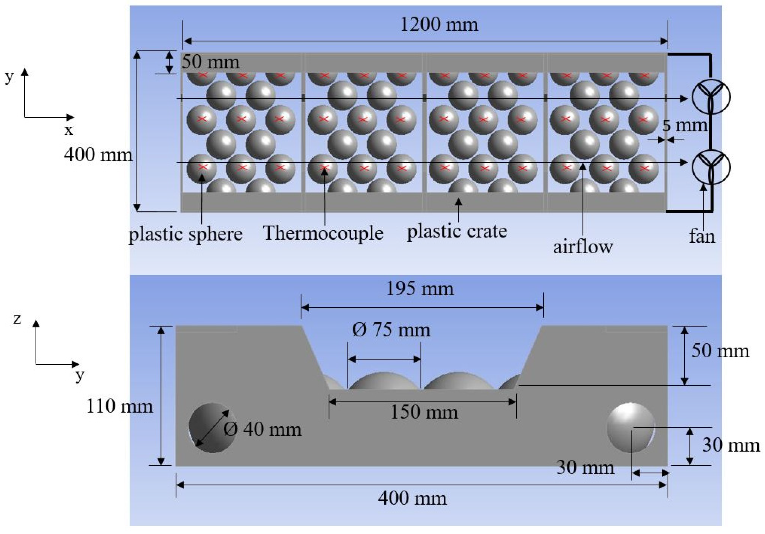
The current pallet arrangement applied in industry is made up of 128 crates packed identically on 16 layers, with 8 crates per layer (Figure 1). In this study, a single layer of a pallet was considered. Due to the symmetrical nature of the crates arranged on each layer, the experimental bench corresponded to half of a layer, i.e., 4 crates. This choice was motivated by the reduction in the size of the computational domain in the CFD study (Section 2.2), leading to less calculation time.

2.1. Experimental Study

2.1.1. Experimental Bench

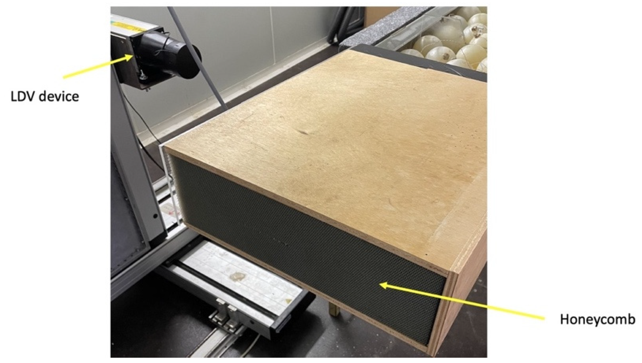
The experimental bench consisted of 4 transparent poly(methyl methacrylate) (PMMA) crates placed adjacent to one another along the direction of airflow. Each crate had a length of 300 mm, a width of 400 mm, a height of 110 mm, and a wall thickness of 5 mm (Figure 2). A trapezoidal opening and two circular holes of 40 mm in diameter were made at the front and back sides of the crates to serve as inlets and outlets of the airflow. In order to represent half of a pallet layer sandwiched between two other layers (top and bottom), the top, bottom, and lateral sides of all of the crates were insulated by a 40 mm thick layer of polystyrene foam. A 500 mm long wooden tunnel with a 400 × 100 mm opening and a wall thickness of 10 mm was attached to the front end of the first crate (Figure 3) to stabilise the airflow before its entrance into the first crate. One of the sides of the wooden tunnel was replaced with Plexiglas to allow LDV (laser Doppler velocimetry) measurements. In addition to the wooden tunnel, a 20 mm thick flow straightener containing circular orifices Ø 2 mm in diameter (honeycomb) was used to further stabilise the airflow while ensuring the uniformity of the velocity and low turbulence levels.
Due to their perishable nature, real tomatoes were replaced with 3 mm thick spherical hollow polyethylene spheres with an external diameter of 75 mm, filled with a carrageenan gel composed of 96% water, 3% carrageenan, and 1% preservatives (vitamin C and sodium benzoate). Due to the gel’s high water content, its thermal properties are very close to those of real tomatoes. The spheres had an average mass of 230 g and a standard deviation of 1.4 g. These spheres were used in different experiments so that the repeatability of the results could be assured. Particular attention was paid to the beefsteak tomato variety also known as Solanum lycopersicum, with a diameter as wide as 150 mm and a mass of up to 450 g.
The spheres were arranged within the crates in a staggered pattern, as illustrated in Figure 2. The spheres were laid directly on the crate bottom, and pulp trays were not used. Type T thermocouples connected to an Agilent LXI data acquisition device were placed at the centre of 9 spheres per crate (Figure 2) in order to measure the evolution of their temperature with respect to time. The global measurement error of the thermocouples and the data acquisition system was estimated to be ±0.2 °C after calibration of the thermocouples within the temperature range of 0–30 °C. Two axial RS PRO 24 V DC fans placed at the exit of the experimental setup were used to generate a negative pressure gradient that enabled the flow of air from the opening of the tunnel to the exit of the last crate. The power supplied to the fans was adjusted to obtain the desired air velocity at the entrance of the tunnel.
The velocity at the inlet of the tunnel leading to the vented crates was measured using an LDV device (Dantec FlowExplorer-2D), with the help of an Antari F-80Z smoke generator that injected small oil droplets (~Ø 7 µm) into the air during the measurements. This device uses 2 laser beams to indirectly measure the velocity of air at a given point. The velocity measurement is indirect because the device measures the velocity of microscopic liquid particles that are injected into the airflow. This experimental setup was placed in a temperature-controlled room (cold room).

2.1.2. Cooling Experiments

At the start of each experiment, the cold room was set to a temperature of 20 °C for approximately 7 h to ensure the temperature uniformity of the products. Then, the entire experimental bench was well insulated with polystyrene foam, and the cold room was set to 6 °C. After the cold room’s air-cooling phase, which lasted 20 min, the insulation was removed from the inlet and the outlet of the experimental bench, and the fans were turned on in order to start the experiment. In this manner, the impact of the cold room’s set temperature change on the initial temperature of the spheres was negligible. The power of the fans was adjusted in order to attain an upwind air velocity in the range of 0.05 to 0.22 m s−1 to represent the airflow velocity range in a cold chain. The average inlet air temperature measured by 4 thermocouples throughout the experiments was 6.1 °C. The experiment was ended when the temperature of all spheres attained a value of 7.8 °C (7/8th cooling time).

2.1.3. Analysis of Cooling Rate and Temperature Uniformity

The analysis of the cooling rate of a single sphere was carried out using the dimensionless temperature θ defined below:
θ t = T t T amb T i T amb
The average dimensionless T* temperature of n spheres was computed from Equation (2) below:
T * t = 1 n i = 1 n θ i t
The half (1/2) and seven-eighths (7/8) cooling times corresponded to T* values of 0.5 (13.0 °C) and 0.125 (7.8 °C), respectively.

2.1.4. Air Velocity Measurement

In order to impose accurate boundary conditions on the model, the air velocity at the inlet of the tunnel leading to the vented crates was measured using an LDV device (Figure 3). The average value of 7 measurements made across the width of the tunnel (equally spaced at mid-height) was used to determine the average upwind velocity and, hence, the airflow rate at the inlet of the setup. These measurements were used to determine the pressure imposed on the outlet boundary of the model. The velocity measurement error was estimated to be 2.3% by the manufacturer. Additional information on the measurement process can be found in the work of Pham et al. [18].

2.2. CFD Modelling

A 3D model of the experimental setup, consisting of 4 crates filled with 15 carrageenan spheres each, was developed using the commercial CFD code ANSYS 21.0. The spheres were separated by a free distance of 3 mm. The model had 3 subdomains, composed of the free airflow fluid zone, the solid spheres zone, and the solid PMMA crates zone. As explained in Section 2.1.1, the main reason for simulating only a single column per pallet layer was to reduce the computational time.

2.2.1. Governing Equations

The Reynolds-averaged Navier–Stokes (RANS) equations were used to resolve the airflow and the heat transfer within the fluid domain. The buoyancy effect was taken into account in the momentum equation in order to model heat transfer by natural convection. The density term was treated by using the Boussinesq approach [19,20], due to the relatively low temperature differences within the computational domain. With this approach, the density is assumed to be constant in all solved equations except for the buoyancy term in the momentum equation. Some assumptions made during this study are as follows:
  • Air is an incompressible fluid with constant properties.
  • Radiation between the carrageenan spheres and the PMMA crates was considered to be negligible.
  • Due to the similarity in the thermal diffusivity of the carrageenan gel with that of polyethylene, the thermal properties of the carrageenan gel were used on the entire volume of the 75 mm diameter sphere.
  • The effect of the experimental instruments on the airflow is negligible.
The equations were closed by using the appropriate turbulence models. In this study, the realisable k-ε model with enhanced wall treatment was used. The enhanced wall treatment approach blends the near-wall viscous sublayer and logarithmic laws by using a function suggested by Kader [21]. The realisable k-ε model has been shown to be effective for similar crate and product arrangements [18,22,23,24,25]. The thermophysical properties of the materials used for the numerical simulations are presented in Table 1.

2.2.2. Initial and Boundary Conditions

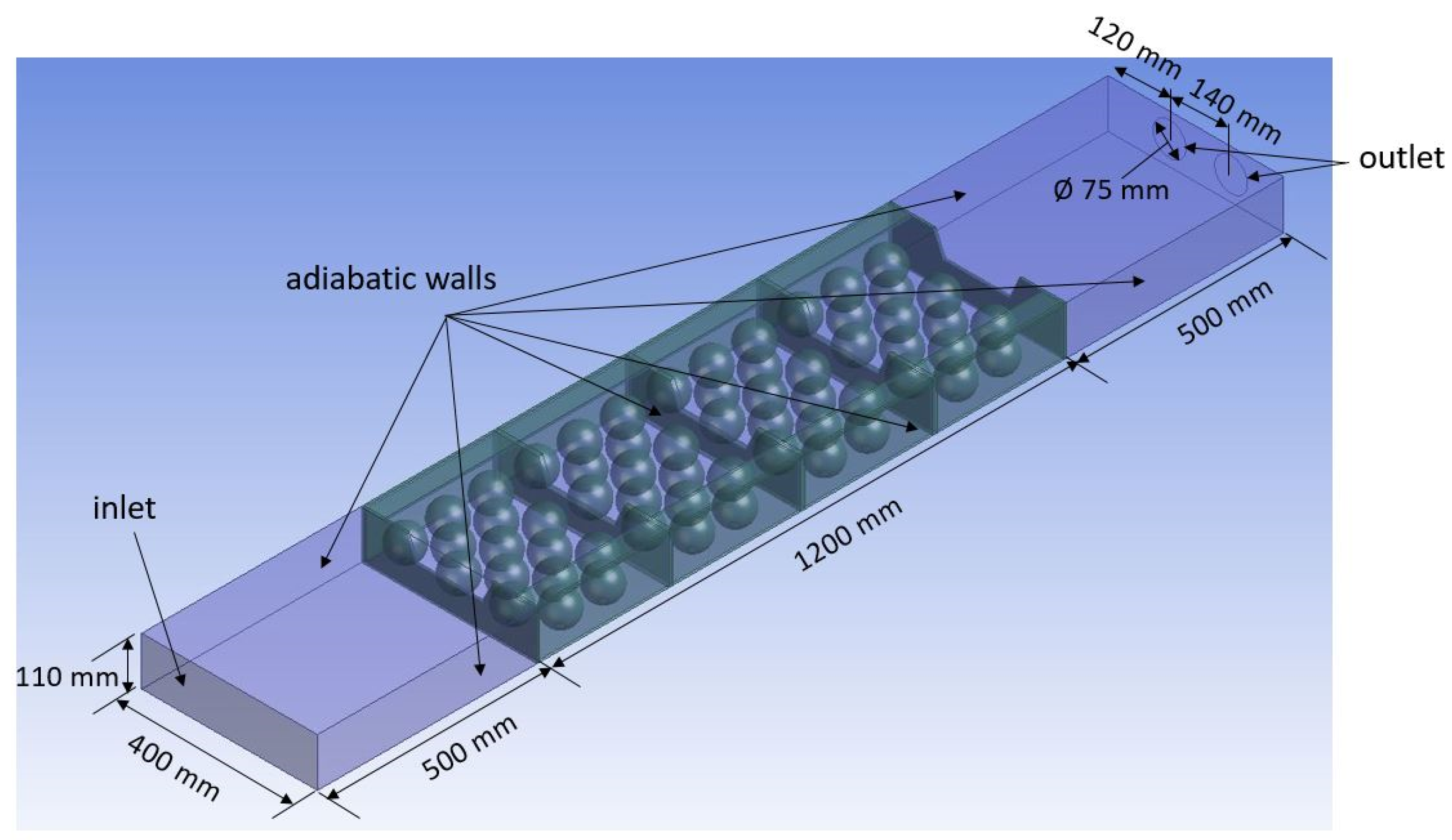
An initial temperature of 20 °C was imposed on the product and the plastic crates. The boundary conditions imposed on the model are illustrated in Figure 4. At the inlet of the domain, ambient atmospheric pressure was imposed. The air temperature measured at the inlet of the tunnel during the experiments (6.1 °C) was used as an inlet boundary condition. A turbulence intensity of 3.2% measured by the LDV device was also imposed at the inlet.
At the outlet, an underpressure representing the effect of the fans was imposed. Its value was optimised to obtain the same air inlet velocity that was measured by the LDV device. The value of the underpressure was in the range of 2 to 7 Pa, which led to corresponding inlet airflow rates of 0.26 L s−1 kg−1 to 0.66 L s−1 kg−1 (Table 2).
A no-slip boundary condition was imposed on the walls of the crates and products. Adiabatic boundary conditions were imposed on the external surfaces of all of the surrounding walls. On the product–air interface, a continuity of temperature and heat flux was imposed.

2.2.3. Mesh Discretisation and Sensitivity Analysis

A hybrid tetrahedral mesh was used for the numerical study. Tetrahedral cells were used for the air and product domains, while hexagonal cells were used for the plastic crates and for the boundary layers at the product–air interface. A coarser mesh was used closer to the inlet and outlet, while a finer mesh was used in the volume occupied by the crates, due to the higher velocity and temperature gradients in the latter zone. A finer mesh was also required due to the narrow 3 mm spaces between the products. Additionally, a fine mesh was used on the products in order to accurately resolve the conduction heat transfer within them. The air domain was extended close to the outlet in order to reduce the influence of the boundary condition on the flow computations.
In order to test the sensitivity of the obtained results to the mesh grid, different grid sizes were tested. Cell numbers of 3 × 10⁶, 6 × 10⁶, and 1.5 × 10⁷ were used to conduct the tests. The average temperature at the product centres, as along with the upwind and downwind air velocity, was compared for the different cell numbers. An average temperature difference of less than 0.2 °C was found between the results obtained from the 6 × 10⁶ cells and the 1.5 × 10⁷ cells grids, but the computation time doubled when the 1.5 × 10⁷ cells grid was used. For this reason, the 6 × 10⁶ cells grid was selected to perform the studies. The wall y+ of the products and the inner crate walls was less than 3. When using the enhanced wall treatment, it is recommended to have a wall y+ of less than 5.

2.2.4. Simulation Procedure

A transient simulation with a time step of 60 s and 30 iterations per time step was carried out. Before launching the transient simulation, the steady-state flow was resolved without taking the energy equation into account. After convergence of the steady-state flow problem, the transient simulation was launched after activating the energy equation and buoyancy effects. This approach improved the overall convergence of the solution and reduced the computation time. Pressure–velocity coupling was performed using the PISO algorithm. A second-order upwind scheme was used to discretise the equations. A convergence criterion of 10−4 was used for the continuity, momentum, and turbulence equations, while a criterion of 10−6 was used for the energy equation.
The simulations were carried out on a 64-bit Windows 10 computer with a 2.4 GHz Intel® Xeon® Silver 4210R CPU and 256 GB of RAM.

2.2.5. Crate Designs

In this study, 3 different crate designs were tested (Figure 5). These designs were called crate A (Figure 5a, 11% TVA), crate B (Figure 5b, 14% TVA), and crate C (Figure 5c, 15% TVA). The CFD model was validated against the experimental results obtained from the crate A and B designs.
Due to the presence of lateral orifices on the crate C design, the boundary conditions had to be modified to take these changes into account. A symmetry boundary condition was imposed on the orifices located on the side of the crate adjacent to another crate on the same pallet, while a pressure inlet (atmospheric pressure) was imposed on the orifices located on the side of the crate in contact with the ambient air of the wind tunnel in the precooling process.
The size of the orifices on the lateral sides of the crate C design was optimised to maximise the cooling rate of the products and their temperature homogeneity. This was done by testing different orifice diameters. The size that enabled the optimal temperature uniformity and cooling speed was retained.
In the course of the simulations, the number of mesh elements used for the crate A, crate B, and crate C designs was 5.94 × 10⁶, 5.87 × 10⁶, and 5.90 × 10⁶, respectively.

2.2.6. Prediction Error and Temperature Uniformity

The prediction error was evaluated by comparing the temperature values obtained from the model to the temperature measurements performed experimentally using the root-mean-square error (RMSE) and the absolute relative deviation (ARD) of the predicted values compared to the measured values.
RMSE = i = 1 n T m t T s t 2 n
ARD = 1 n i = 1 n T m t T s t T m t × 100
where n is the number of instrumented products, Tm represents the temperature measurements made at the centres of the selected products, and Ts represents the temperature values obtained from the CFD computations.
The temperature uniformity of the products was evaluated by calculating the maximum temperature difference (MTD) and average temperature difference (ATD) at HCT. This approach enables the determination of the level of undercooling of certain products within the crates and, hence, a possible evaluation of the deterioration in quality of the undercooled products. The analysis was conducted at the pallet layer level and at the crate level by calculating the maximum temperature difference and average temperature difference of the products in the pallet layer and in the individual crates, respectively. When calculating the ATD, n was equal to 9 when the analysis was performed at the crate level and equal to 36 when the analysis was performed at the pallet level.
MTD = T max T min
ATD = 1 n i = 1 n T i T avg
The RMSE and ARD were calculated from the measurements made at the centres of the 36 selected products (9 per crate). The HCT corresponds to the time where the average dimensionless temperature (T*) of the selected products reaches 0.5.

3. Results and Discussion

3.1. Model Validation

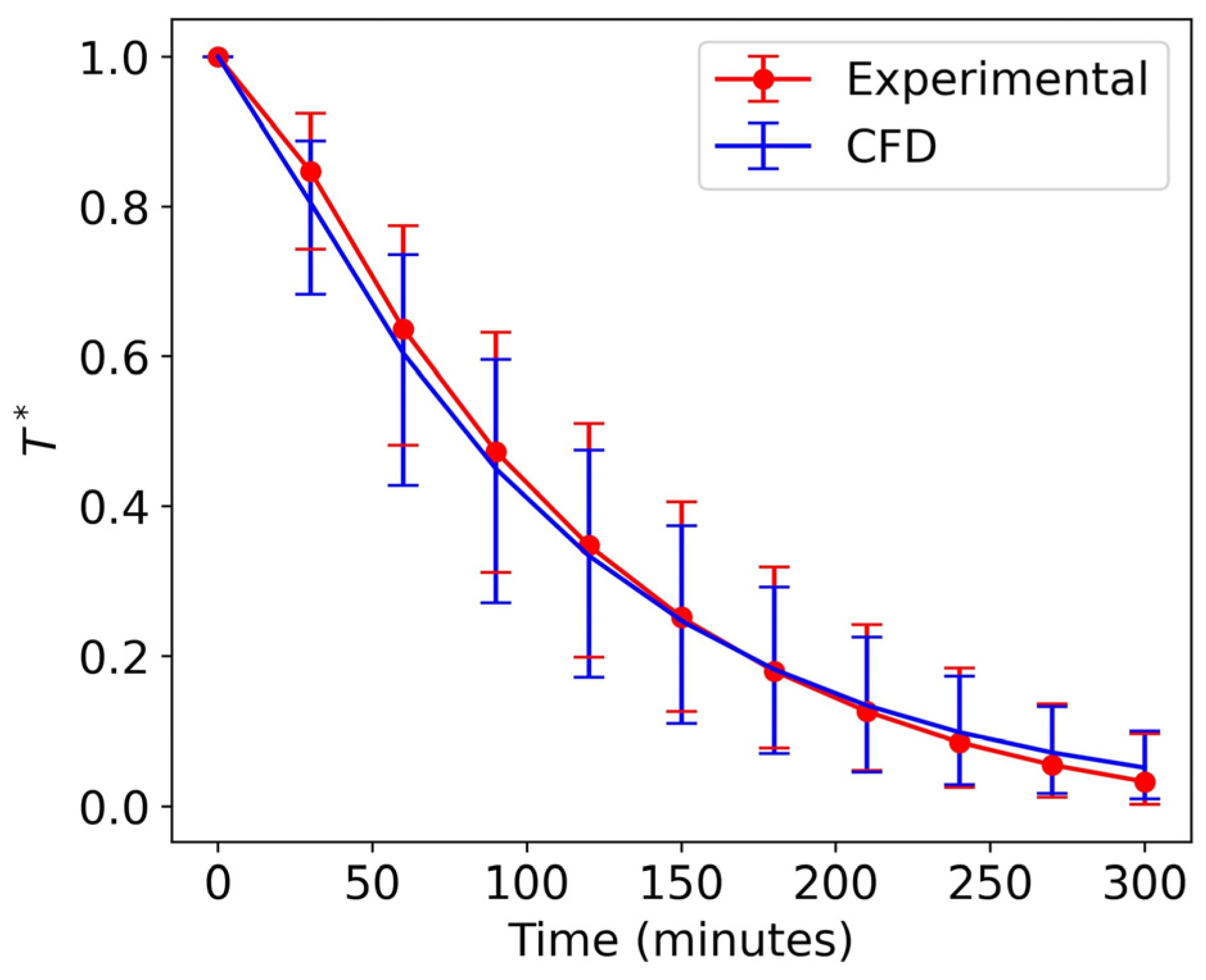
The ability of the model to predict the cooling rate and temperature uniformity of the products was evaluated by comparing the numerical results to the experimental results. Figure 6 illustrates the evolution of the average dimensionless temperatures obtained experimentally and numerically. The vertical bars represent the maximum and minimum temperature values at a given time step.
It can be observed from the figure that there was a good fit between the experimental and numerical results, with an RMSE value of 0.48 °C and an ARD of 3.56%, as presented in Table 3. In addition to the average temperatures at a given time step, the model was able to accurately predict the maximum temperature difference of all of the products at the corresponding time steps, as represented by the vertical bars.
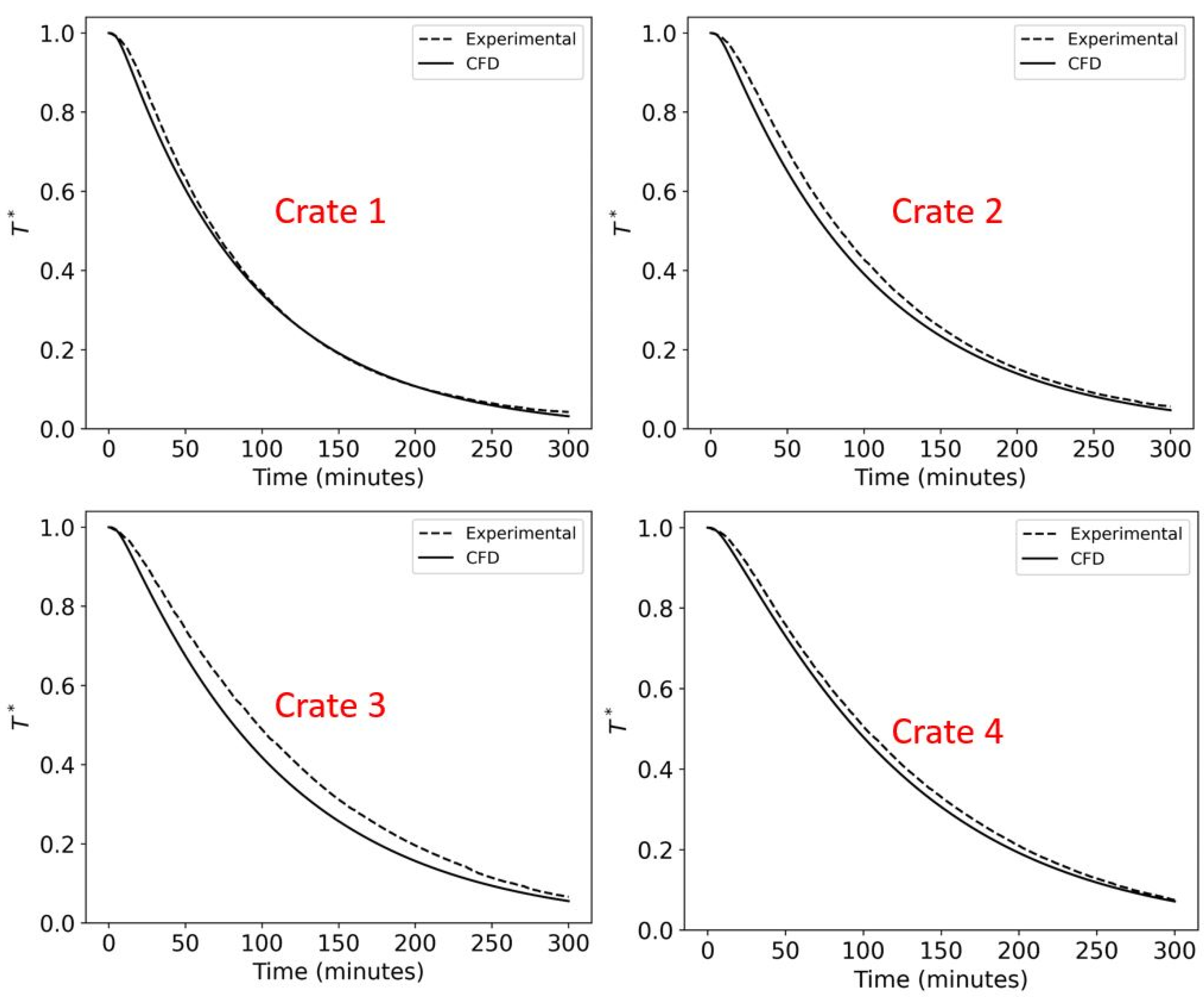
In order to perform a more localised analysis of the model’s accuracy, the experimental and numerical average dimensionless temperatures of products in a single crate were compared. We can observe from Figure 7 that when the experimental and numerical dimensionless temperatures of the products at the crate level are compared, the model data fit the experimental data rather accurately.
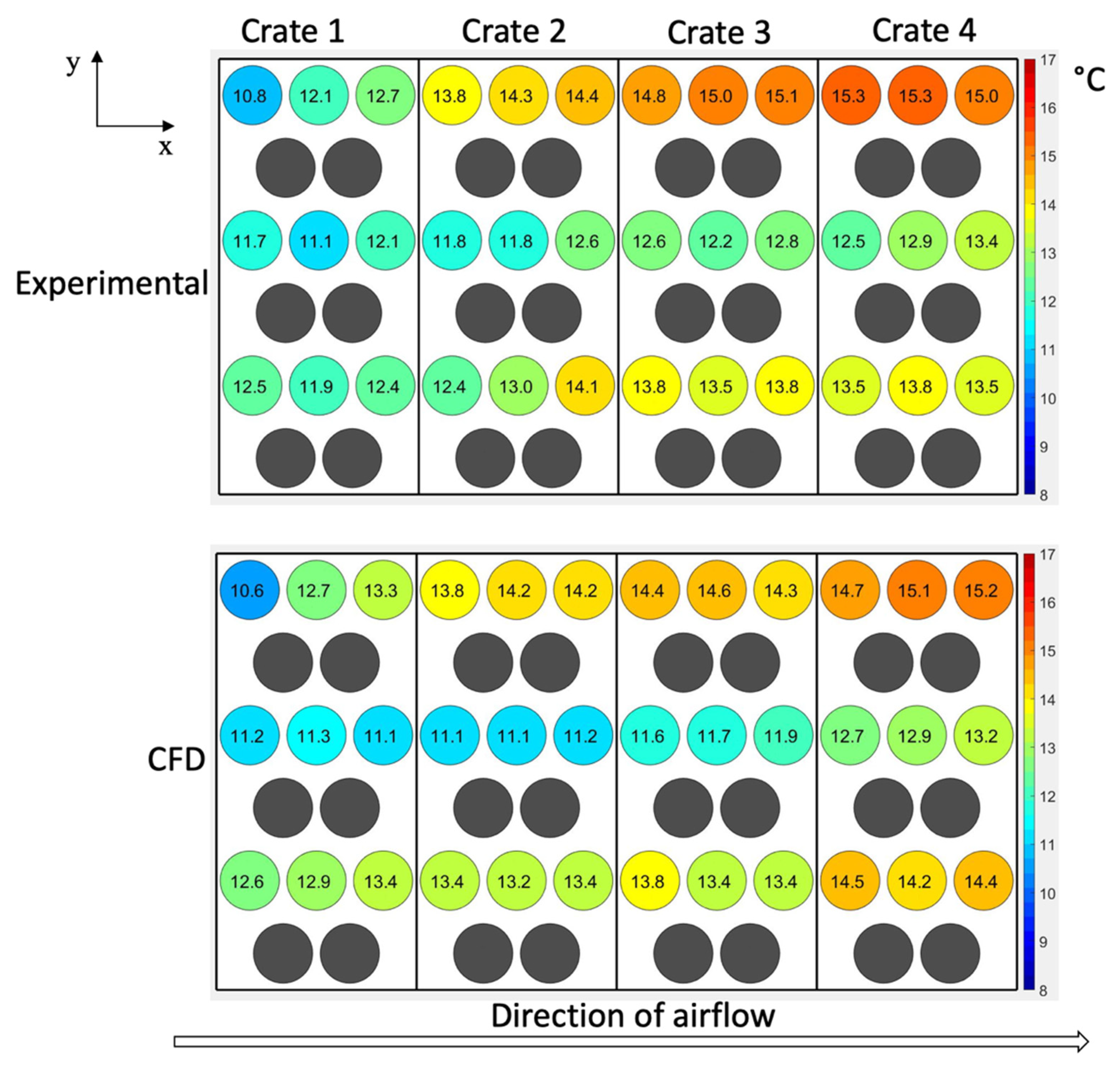
Figure 8 depicts a visual representation of the temperature distribution of the products at HCT. This figure illustrates that, in addition to the ability of the model to predict the cooling kinetics of the products, the model is also able to predict the temperature heterogeneity of the products packed within the crates, with good precision. The HCT obtained experimentally was 90 min, while that obtained numerically was 78 min, for an airflow rate of 0.66 L s−1 kg−1.
Different approaches were used to validate the ability of the CFD model to predict the cooling kinetics and temperature heterogeneity of the cooled products. This involved determining the RMSE and ARD of the numerical results from the experimental results. In addition to the model’s ability to predict the cooling kinetics of the products, its ability to predict their temperature heterogeneity was also evaluated. The model predicted the cooling kinetics and the temperature heterogeneity of the products packed in the crates with RMSE values of less than 1 °C, ARD values of less than 6%, and an HCT difference of 13%. The highest RMSE and ARD values were obtained from crate 3 with values of 0.71 °C and 5.5%, respectively. The RMSE and ARD values of all of the individual crates are presented in Table 3. The deviations of the numerical results from the experimental results were due to assumptions made during the modelling process. After the validation of the model, it was used to perform further analysis on the influence of parameters such as airflow rate and crate design on the product cooling rate and temperature uniformity.

3.2. Airflow Analysis of the Confined Wall Jet (Crate A Design)

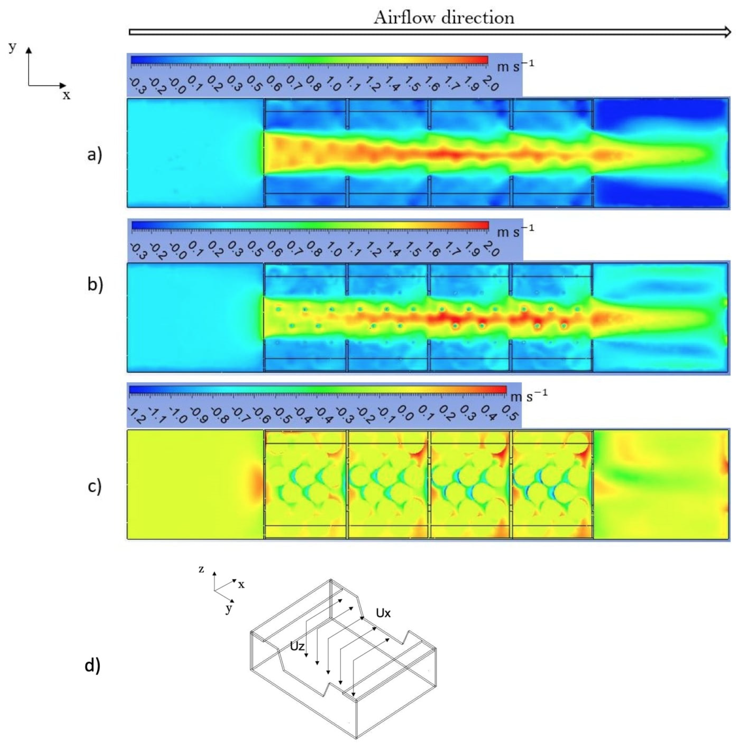
Figure 9a illustrates the ux velocity contours in the air headspace at a 10 mm distance above the top of the products, while Figure 8b illustrates the ux velocity contours at the top surface of the products for the crate A design. It can be observed from Figure 9a,b that the jet issuing from the trapezoidal vent of crate 1 behaves as a confined wall jet (CWJ) and develops as a wall-bounded flow within the enclosed space of the crates. Additionally, the jet strongly interacts with the spheres. These aspects affect the wall jet development and cause substantial differences compared to a free wall jet.
Wall jets constitute a fundamental academic case, since they have a wide range of industrial applications, such as ventilation or air conditioning of a room [28,29,30,31,32].
Due to the diffusion process, a free 3D wall jet spreads out in the lateral (i.e., parallel to the wall) and transversal (i.e., normal to the wall) directions, which causes a decrease in the air jet velocity and an increase in the mass flow rate of the jet due to entrainment mechanisms from the ambient air [33]. Forthmann et al. [34] demonstrated that the maximum velocity decreases according to the law 1 x , where x denotes the distance from the jet’s exit plane in the streamwise direction.
However, in the studied configuration, due to the confinement effect, the CWJ developed within the enclosed space of the crate with the same airflow rate, due to the lack of entrainment by the jet of the ambient air in the cold room. This limited the lateral diffusion of the jet (along the y axis), which behaved as a channel flow rather than a free wall jet flow (Figure 9a). Additionally, instead of decreasing similarly to a free wall jet, the maximum air velocity (ux) at the trapezoidal inlets of the crates increased gradually as the air flowed from one crate to another. The maximum velocities were 1.5, 1.65, 1.83, and 1.80 m s−1 at the inlets of crate 1, crate 2, crate 3, and crate 4, respectively. This increase in the local maximum velocity reflects strong interactions between the jet and the products, with the maximum velocities located at close proximity to the products due to jet attachment by wall adherence (Coanda effect) [35].
Furthermore, the analysis of the numerical data indicates a significant change in the jet development through the different crates. At the inlet of crate 1, the jet flow was uniformly distributed along the y-axis; meanwhile, as the airflow progressed from crate 1 to crate 4, the uniform jet profile changed progressively to a sharp profile (Figure 9a,b). Higher jet velocities can also observed in the jet core, with a wavy jet trajectory slaloming between the centrally located products due to their staggered arrangement in the crates.
Along the airflow direction, the emergence of a vertical jet diffusion through the products, which increases progressively from crate 1 to crate 4, can be noticed (Figure 9c). This gives rise to a secondary downward jet flow (uz1/2), which enhances the cooling mechanism of the central spheres located under the jet. Then, this secondary flow returns back up in an upward flow around the products close to the lateral walls of the crates, allowing weak ventilation and slower cooling of these products. Due to the conservation of mass and momentum, the downward airflow is equivalent to the upward airflow and can be defined as follows:
  u z 1 / 2 = 1 2 u z dS
The flow directions of ux and uz are illustrated in Figure 9d. The secondary airflow rates obtained using Equation (7) in the xy plane at a z distance of 37.5 mm from the bottom surface of the crates were 2.7, 3.4, 4.0, and 3.9 L s−1 for crate 1, crate 2, crate 3, and crate 4, respectively.
The behaviour of the wall jet along the trapezoidal inlets and outlets of the crates was similar for the three crate designs (crate A, crate B, and crate C). Circular orifices were included in the crate design (crate B and crate C) to make up for the limitations of the jet flow along the trapezoidal inlets and outlets of the crates.

3.3. Influence of Inlet Velocity on Product Cooling Rate and Temperature Uniformity

3.3.1. Influence of Airflow Rate on Product Cooling Rate

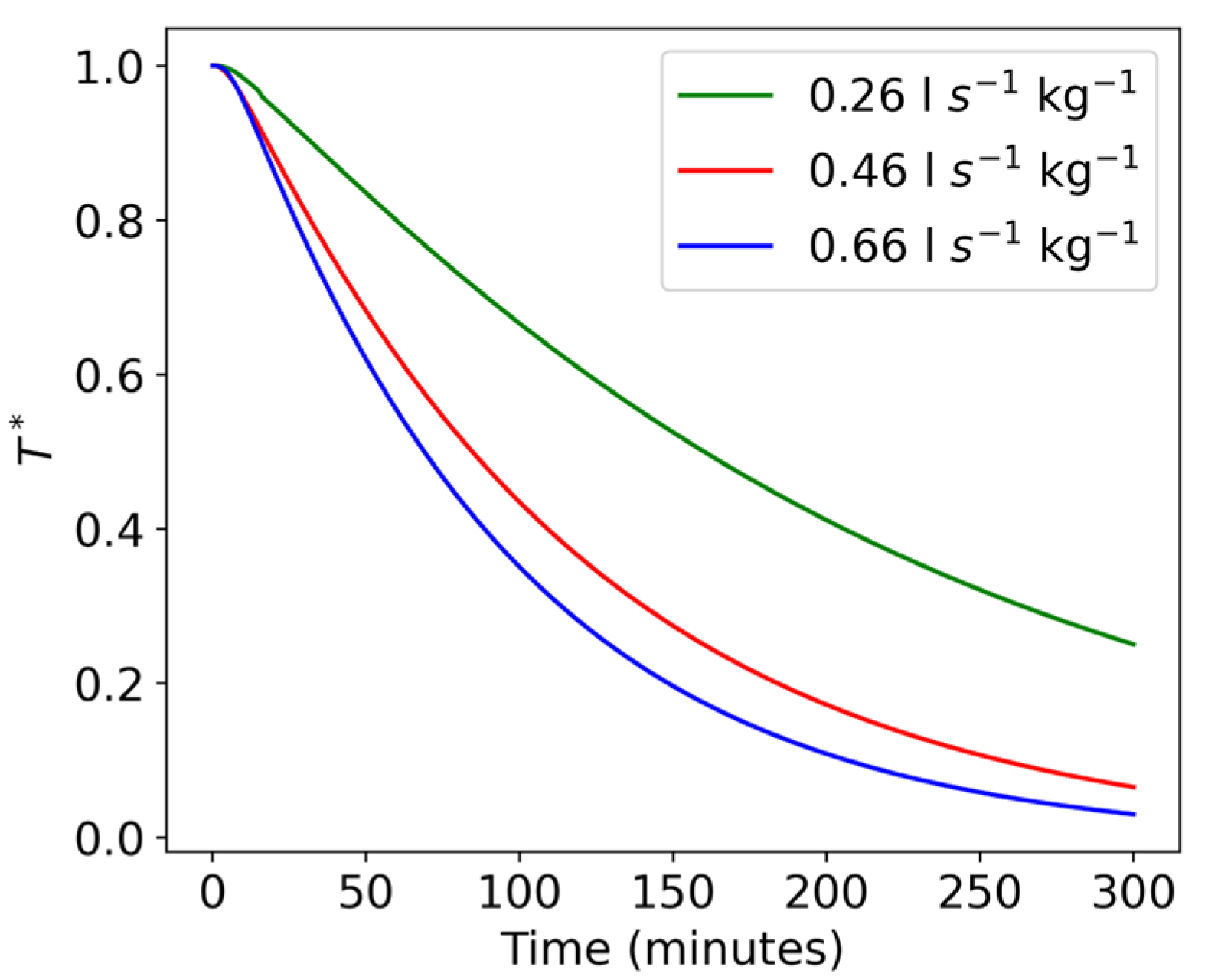
The influence of the airflow rate on the cooling kinetics of the products was studied numerically by applying the validated CFD model (crate B). Figure 10 illustrates the evolution of the average dimensionless temperature of the products with respect to time for different airflow rates. We can observe from the figure that increasing the airflow rate tends to increase the cooling kinetics of the products. The HCTs obtained for airflow rates of 0.26, 0.46, and 0.66 L s−1 kg−1 were 162, 84, and 78 min, respectively. Studies performed by [2,3] revealed that there is a certain threshold above which increasing the airflow rate does not lead to an increase in the product cooling rate. It is for this reason that increasing the airflow rate from 0.46 to 0.66 L s−1 kg−1 (43%) does not lead to a proportional reduction in the HCT (7%).
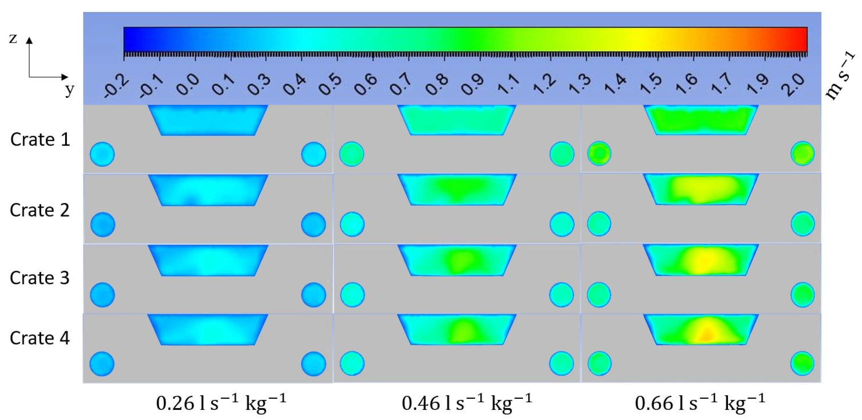
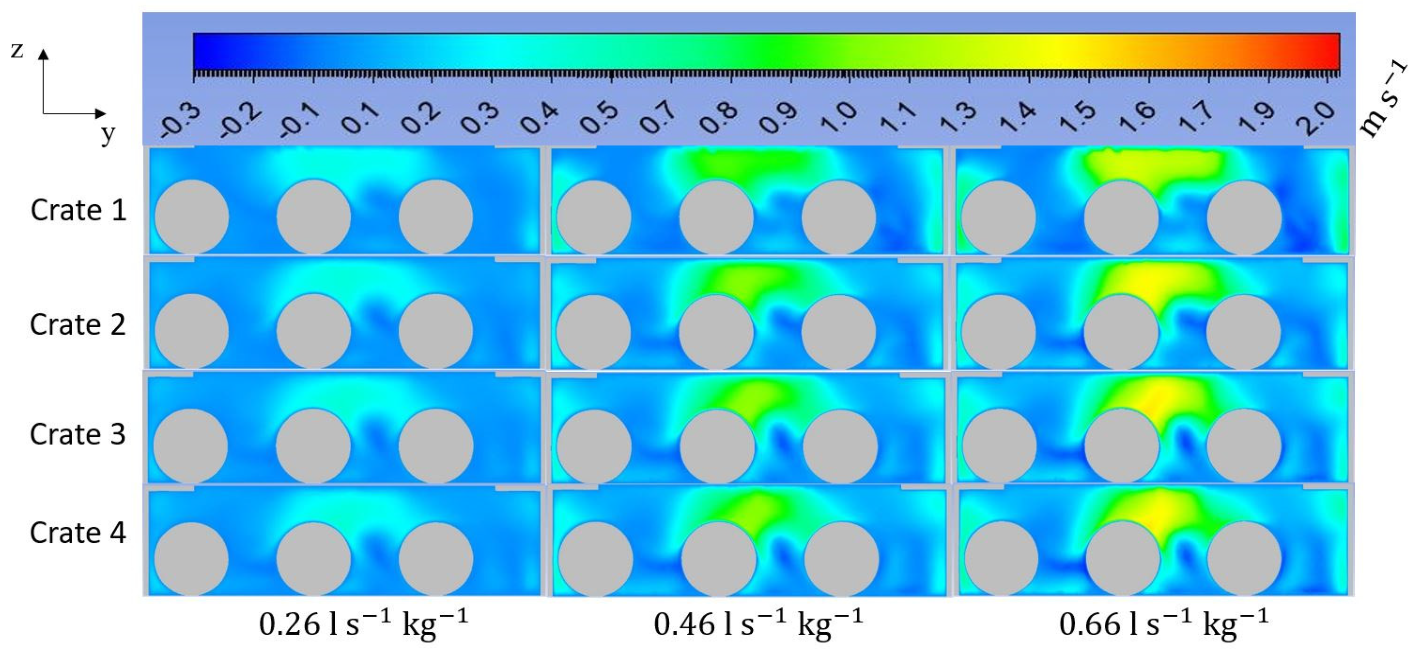
The increase in the cooling kinetics of the products with the airflow rate can be explained by the corresponding increase in the air velocity, as illustrated by Figure 11 and Figure 12. Figure 11 depicts the air velocity at the inlets of all four crates for different airflow rates, while Figure 12 depicts the air velocity midway along the lengths of the crates in the zy plane. The higher air velocity increases the heat transfer coefficient between the air and the products which, in turn, leads to an increase in their cooling rates. The diminishing returns of cooling rate compared to airflow velocity are due to the Biot number and the air boundary layer. As the air velocity increases, the boundary layer reduces in size and the internal resistances dominate instead of the external resistances.
We can observe from Figure 9 and Figure 12 that the zones with the highest air velocity are located above the products along the path of least airflow resistance, directly facing the main trapezoidal inlets and outlets of the crates. Some areas of relatively high air velocity can also be found on the sides of the crates due to the presence of circular orifices at the front and back of the crate B design (Figure 12). The impact of this non-uniform velocity on the temperature uniformity of the products is analysed in Section 3.3.2.

3.3.2. Influence of Airflow Rate on Product Temperature Uniformity

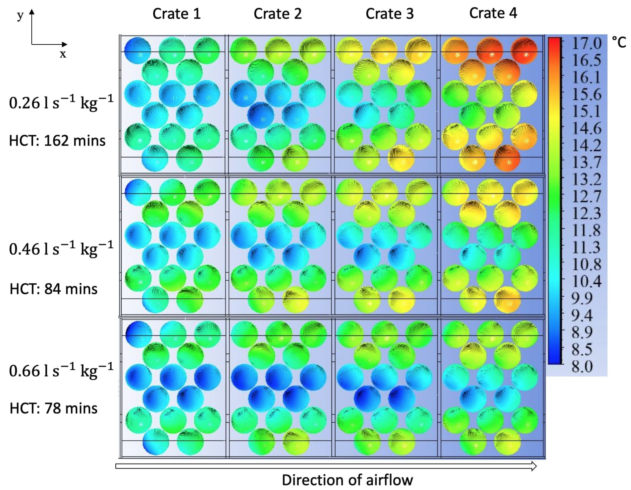
Figure 13 illustrates the temperature distribution of the products in the four crates at HCT for different airflow rates. We can observe from the figure that the products that are centrally located are at a lower temperature compared to the products that are closer to the lateral sides of the crates. This can be explained by the better ventilation of the central areas of the crates compared to the areas located closer to their lateral sides, as observed in Section 3.2 and Section 3.3.1. Another observation is the fact that the products become progressively warmer as we move from crate to crate in the airflow direction. This is due to the progressive heating of the air as it flows from one crate to another, as illustrated in Table 4. When the air becomes warmer, this reduces the temperature difference between the product surface and the air, leading to a lower heat flux for a comparable air velocity along the crates. The observations described remained the same regardless of the airflow rate that was applied.
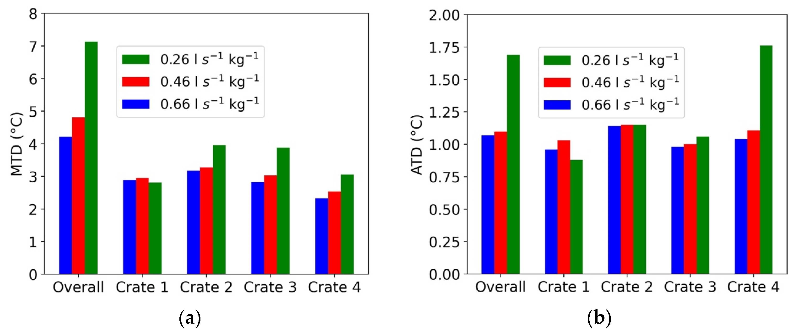
In order to evaluate the influence of the airflow rate on the disparity in the product temperatures at the pallet layer and crate levels, the maximum temperature differences (MTDs) and average temperature differences (ATDs) were analysed. Figure 14 depicts the MTD and ATD at the pallet layer and crate levels for three different airflow rates. It can be discerned from Figure 14a,b that increasing the airflow rate reduces the MTD and ATD at the pallet layer level and in most crates for the crate designs studied here. This could be explained by the reduction in the temperature differences of the airflow within the crates when the airflow rate increases. For an airflow rate of 0.26 L s−1 kg−1, the temperature difference between the air at the inlets of crate 1 and crate 4 was 6.1 °C; meanwhile, for an airflow rate of 0.66 L s−1 kg−1, the temperature difference of the air between the same inlets was 3.4 °C (Table 4). Given the fact that the air velocity field did not vary significantly from crate to crate, the main reason for the disparity in the cooling kinetics of the products located in different crates must have been the air temperature difference.
In order to improve upon the temperature uniformity of the products packed in the crates, a new design that seeks to eliminate the limitations of the crate A and B designs is proposed. The main change to the design was the addition of two circular orifices to both lateral sides of the crates. The aim of this modification was the improvement of the ventilation of the products that are located close to the lateral sides of the crates, thereby limiting the differences in their cooling kinetics. Another advantage of this design is the reduction in the air temperature differences between the crates due to the continuous supply of cooler air from the lateral sides of the four crates facing the ambient air of the cold room.

3.4. Influence of Crate Design on Product Cooling Rate and Uniformity

3.4.1. Influence of Crate Design on Product Cooling Rate

The influence of the crate design on the cooling kinetics of the products was analysed. Three different crate designs named crate A, crate B, and crate C (Figure 5) were tested.
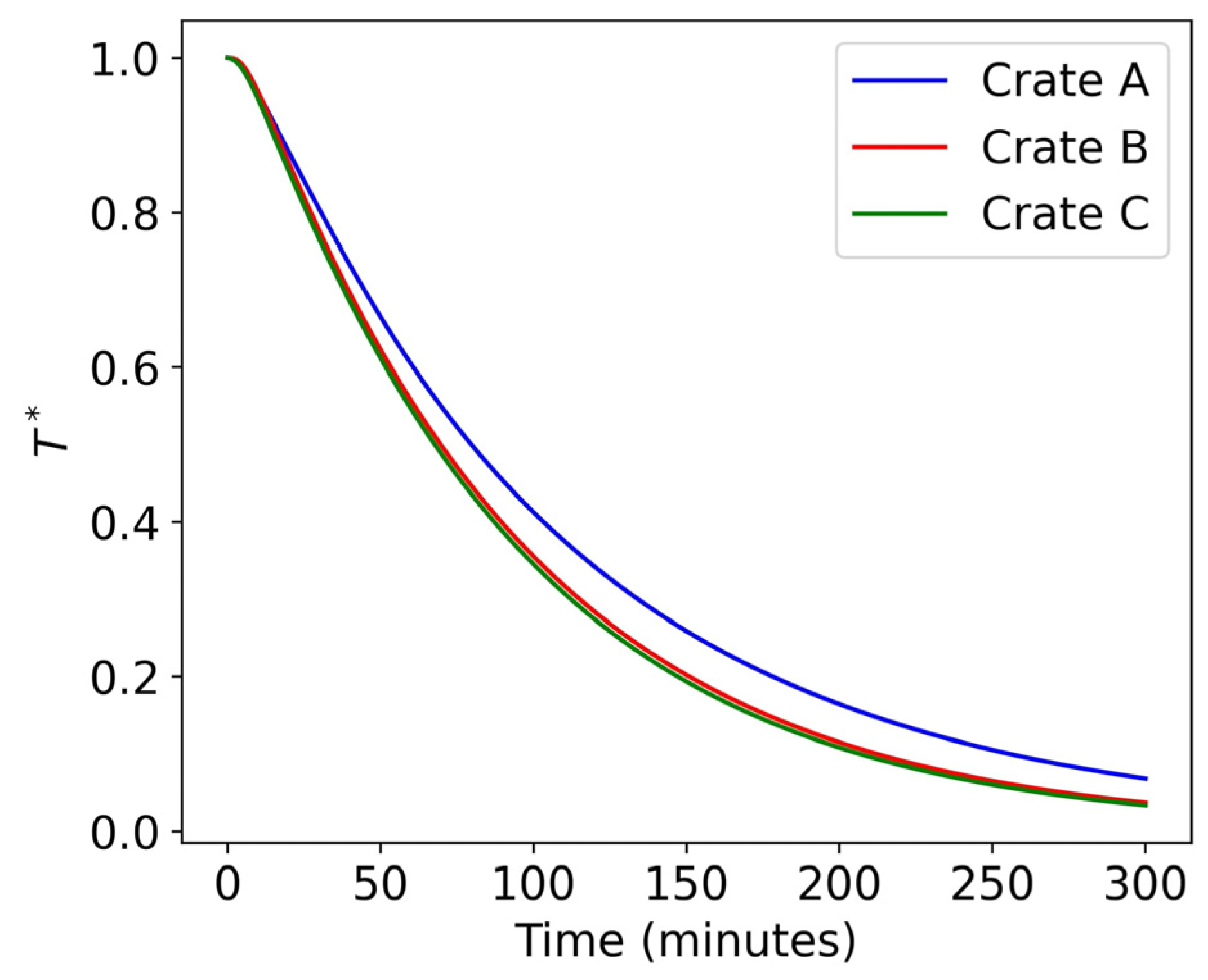
Figure 15 illustrates the evolution of the average dimensionless temperature of the products with respect to time for the three different crate designs at a pressure drop of 4.5 Pa between the inlets and the outlets of the pallet layer. It can be observed from the figure that the highest cooling rate was obtained with the crate C design, from which we obtained an HCT of 68 min, followed by the crate B and crate A designs, with HCTs of 69 min and 79 min, respectively. The airflow rate for the pressure drop of 4.5 Pa was 0.58, 0.66, and 0.78 L s−1 kg−1 for crate A, crate B, and crate C, respectively.
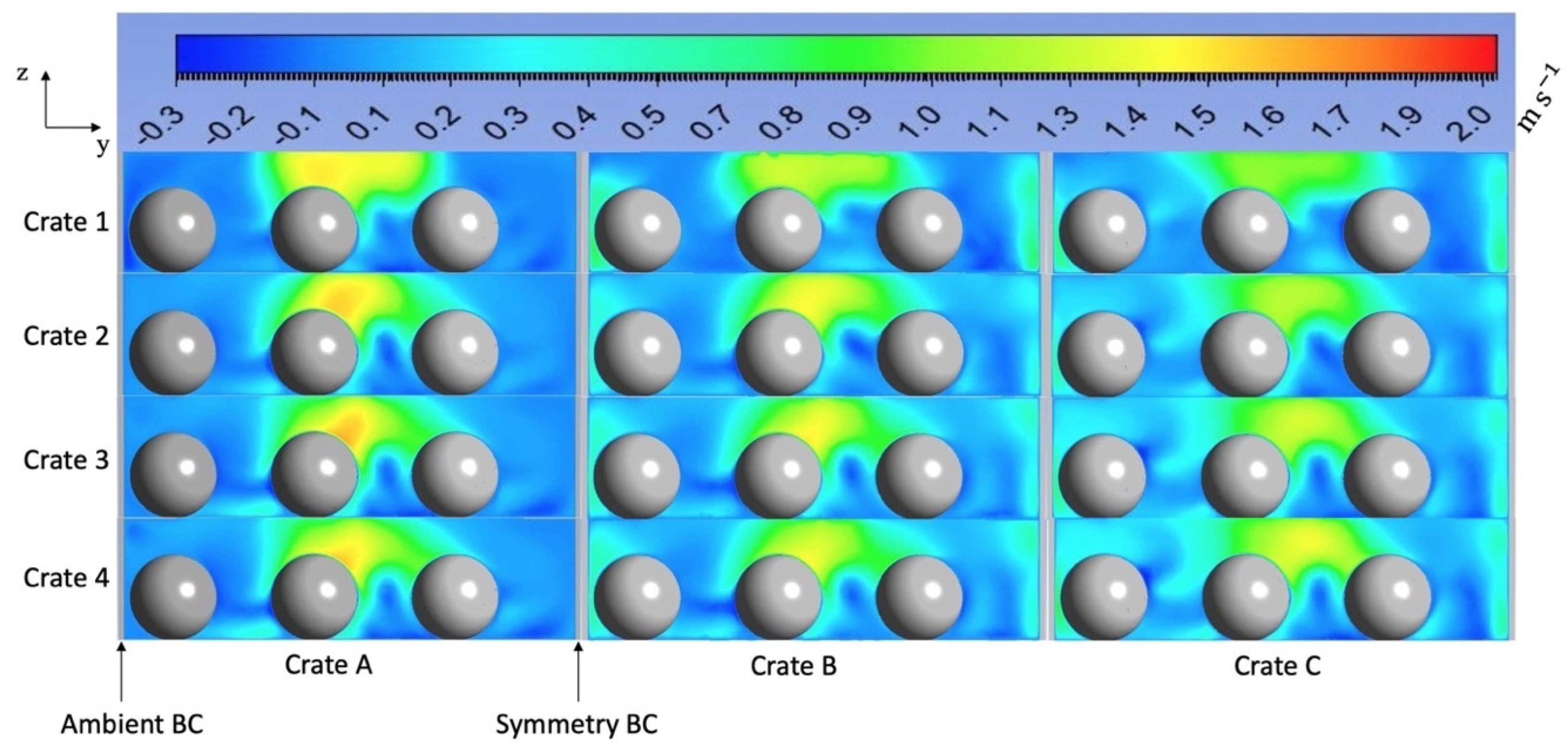
The difference in the cooling rates can be attributed to the difference in the air velocity fields within the different crate designs, as illustrated on Figure 16. On crate A, there is a single trapezoidal opening at the front and back ends of the crate. It can be observed from Figure 9 and Figure 16 that most of the airflow is constrained by the openings, with little airflow towards the lateral sides of the crates. For this reason, the products that are centrally located are well ventilated, while those located close to the lateral sides of the crates have relatively low ventilation. In addition to the trapezoidal openings, crate B has two circular orifices at the front and back ends of the crates. These orifices are located close (3 cm) to the lateral sides of the crates (Figure 2). This design improves the overall ventilation of the products in the crates, due to the redistribution by the circular orifices of some of the airflow towards the products located close to the lateral sides of the crates.
The additional orifices of crate B, as compared to crate A, increase the airflow rate while reducing the velocity magnitude at the trapezoidal inlet. This leads to a more homogenous airflow which, in turn, improves the corresponding cooling kinetics of the products, leading to an HCT of 69 min for crate B compared to an HCT of 79 min for crate A. The crate C design further improves the ventilation of the products due to the addition of circular orifices on the lateral sides of the crates. However, the addition of orifices to the lateral sides does not significantly improve the cooling kinetics of the products compared to crate B, with an HCT of 68 min for crate C and an HCT of 69 min for crate B.

3.4.2. Influence of Crate Design on Product Cooling Uniformity

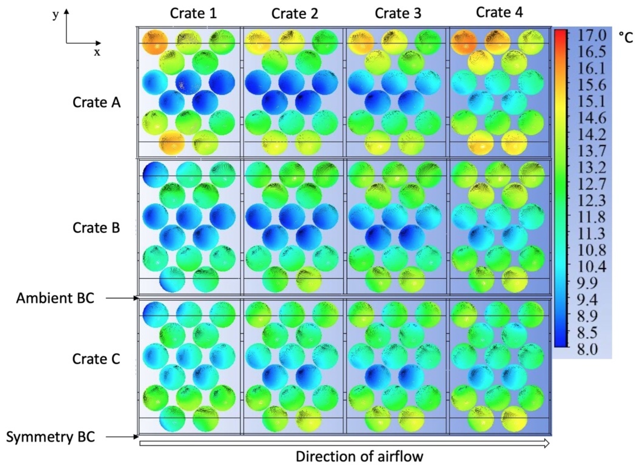
Figure 17 depicts the influence of the crate design on the product temperature uniformity at a pressure drop of 4.5 Pa and at HCT. It can be observed from the figure that for crate A, the products located at the central areas of the crates have a lower temperature relative to products located close to the lateral sides of the crates. Additionally, the products become progressively warmer from one crate to the next in the direction of the airflow.
For crate B, the temperature heterogeneity between the products located centrally and the products located closer to the lateral sides is reduced compared to crate A, due to the presence of additional orifices close the lateral sides that improve the ventilation of the product; however, the product still progressively becomes warmer from crate to crate in the airflow direction.
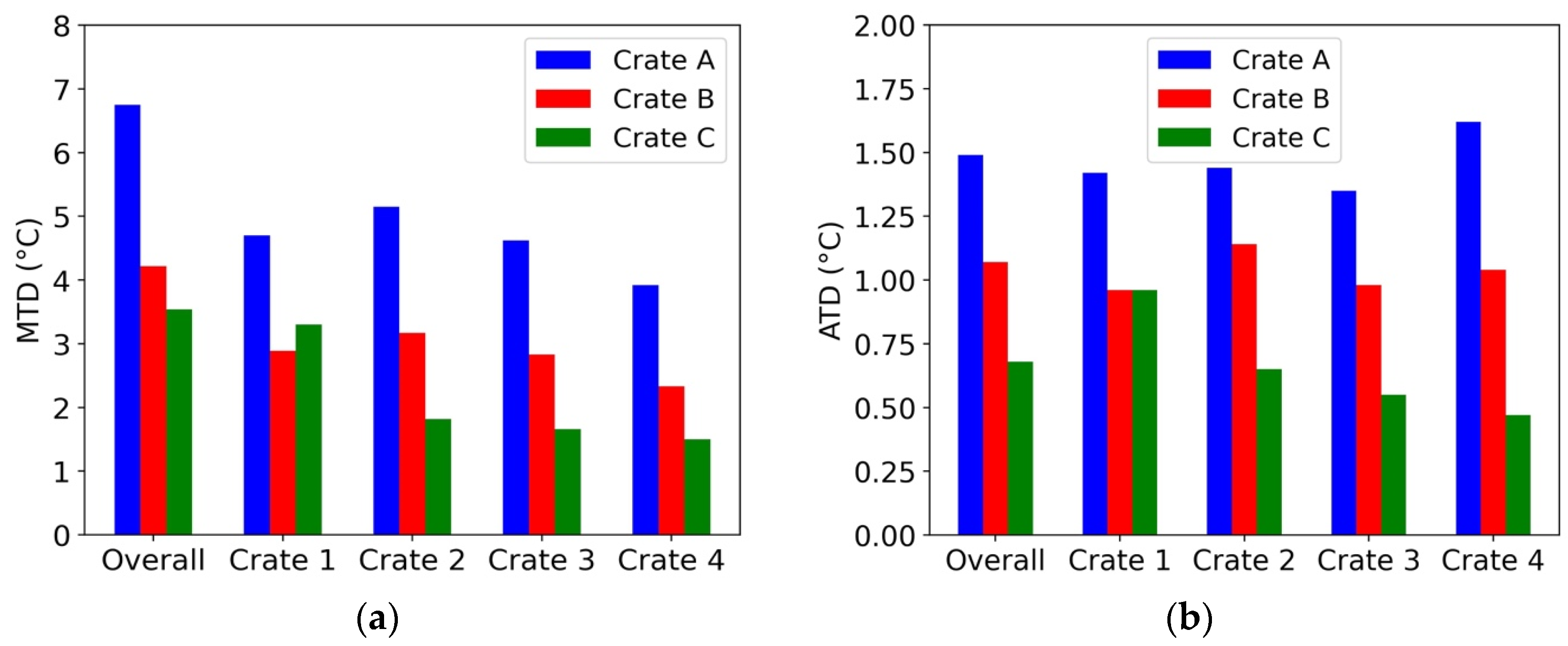
When the crate C design is used, the temperature uniformity of the products is improved as a result of the presence of orifices on the lateral sides of the crates. This improves the ventilation of the products located close to these sides, thereby reducing the temperature heterogeneity of the products. Moreover, due to the introduction of cooler air into the crates from their lateral sides, which are in contact with the ambient air of the room, the effect of the progressive heating of the air as it flows from crate to crate is reduced. This leads to a reduction in the MTD and ATD at the pallet layer level and in most crates, as illustrated in Figure 18.
It can be observed from Figure 18a,b that the simplest crate design (crate A) has the worst cooling performance with respect to temperature uniformity, with an overall MTD of 6.8 °C and ATD of 1.5 °C, compared to an overall MTD and ATD of 4.2 °C and 1.1 °C, respectively, for crate B, and 3.5 °C and 0.7 °C, respectively, for crate C.

4. Conclusions

CFD was applied to resolve the airflow and heat transfer in half of a pallet layer of tomatoes. A 3D transient model of the pallet layer was developed to predict the cooling kinetics and the temperature heterogeneity of the products packed within the crates under different cooling conditions. The model was validated by comparing the numerical results to the results obtained experimentally under similar conditions. A good agreement could be found between the model and experimental results. The validated model was then used to perform the required studies.
In the crate A design, a confined wall jet behaviour was observed along the trapezoidal openings of the crates, with the presence of a uniform velocity profile along the inlet of crate 1, which progressively changed to a sharp velocity profile from crate 1 to crate 4. Higher jet velocities could also be observed in the jet core, which had a wavy jet trajectory slaloming between the centrally located products due to their staggered arrangement in the crates. Moreover, the confinement effect and the jet interaction with the products limited the diffusion of the jet laterally. This led to the development of a downward flow under the jet, which flowed back up close to the lateral walls of the crates. This airflow pattern leads to a weak ventilation of the products located close to the lateral walls of the crates compared to the centrally located products. In order to reduce the temperature heterogeneity caused by the heterogeneous airflow, crates B and C were designed.
The studies performed on the influence of the airflow rate on the product temperature uniformity and cooling rate revealed that, for the crate designs tested, increasing the airflow rate improved the overall temperature uniformity of the products by reducing the MTD and ATD, while also increasing the product cooling rate. The improvement in the temperature uniformity could be explained by the reduction in the air temperature difference between the crates, leading to a reduction in the disparity of the heat transfer between the air and the products in different crates. However, the increase in the product cooling rate with an increase in the airflow rate could be explained by the higher heat transfer coefficients between the products and the airflow resulting from the augmentation of the air velocity magnitudes within the crates. Furthermore, a study on the influence of the crate design on the product temperature uniformity and cooling rate revealed that the crate design with the highest TVA (crate C) improved the overall temperature uniformity and cooling kinetics of the products. This can be explained by the fact that optimising the design, size, and position of the vents makes the ventilation of the products more uniform. Additionally, the introduction of cooler air from the lateral orifices of the crate C design reduces the air temperature heterogeneity within the crates, leading to an improvement in the temperature homogeneity of the products.

Author Contributions

E.K.K.A.: Investigation, Formal Analysis, Methodology, Writing—Original Draft, Visualisation; S.D.: Conceptualisation, Data Curation, Writing—Review and Editing; D.F.: Writing—Review and Editing, Conceptualisation, Resources; O.L.: Funding Acquisition, Conceptualisation, Writing—Review and Editing, Project Administration; J.M.: Writing—Review and Editing, Validation, Supervision, Conceptualisation. All authors have read and agreed to the published version of the manuscript.

Funding

This research was funded by the French Ministry of Agriculture grant number APP 2019 No. 19ART334141 and the APC was funded by INRAE.

Data Availability Statement

Research data will be provided upon request.

Acknowledgments

This study was carried out within the framework of the FreshQualiTom project, benefiting from a grant from the French Ministry of Agriculture (APP 2019 No. 19ART334141).

Conflicts of Interest

The authors declare that they have no known competing financial interests or personal relationships that could have appeared to influence the work reported in this paper.

Nomenclature

ARDAbsolute relative deviation%
ATDAverage temperature difference°C
CWJConfined wall jet
HCTHalf-cooling times
MTDMaximum temperature difference°C
PPressurePa
QFlow rateL s−1 kg−1
RMSERoot-mean-square error°C
SSurface aream2
TTemperature°C
TVATotal ventilated area%
uVelocitym s−1
Greek symbols
ρDensity[kg m−3]
θDimensionless temperature θ t = T t T amb T i T amb
µDynamic viscositykg m−1 s−1
δijKronecker delta
CpSpecific heatJ kg−1 K−1
λThermal conductivityW m−1 K−1
αThermal expansion coefficientK−1
tTimes
εTurbulent dissipation ratem2 s−3
kTurbulent kinetic energym2 s−2
µtTurbulent viscositykg m−1 s−1
Dimensionless numbers
PrtTurbulent Prandtl number
CµEmpirical constant
Indices
aAir
ambAmbient
*Average dimensionless temperature T * t = 1 n i = 1 n θ i t
avgAverage
iInitial
maxMaximum
minMinimum
mMeasured
oOperating
pProduct
sSimulation

References

  1. Defraeye, T.; Cronjé, P.; Berry, T.; Opara, U.L.; East, A.; Hertog, M.; Verboven, P.; Nicolai, B. Towards integrated performance evaluation of future packaging for fresh produce in the cold chain. Trends Food Sci. Technol. 2015, 44, 201–225. [Google Scholar] [CrossRef]
  2. Han, J.; BadÍa-melis, R.; Yang, X.; Ruiz-garcia, L.; Qian, J.; Zhao, C. CFD Simulation of Airflow and Heat Transfer During Forced-Air Precooling of Apples. J. Food Process Eng. 2017, 40, e12390. [Google Scholar] [CrossRef]
  3. Han, J.-W.; Zhao, C.-J.; Qian, J.-P.; Ruiz-Garcia, L.; Zhang, X. Numerical modeling of forced-air cooling of palletized apple: Integral evaluation of cooling efficiency. Int. J. Refrig. 2018, 89, 131–141. [Google Scholar] [CrossRef]
  4. Wu, W.; Defraeye, T. Identifying heterogeneities in cooling and quality evolution for a pallet of packed fresh fruit by using virtual cold chains. Appl. Therm. Eng. 2018, 133, 407–417. [Google Scholar] [CrossRef]
  5. Laguerre, O.; Denis, A.; Bouledjeraf, N.; Duret, S.; Bertheau, E.D.; Moureh, J.; Aubert, C.; Flick, D. Heat transfer and aroma modeling of fresh fruit and vegetable in cold chain: Case study on tomatoes. Int. J. Refrig. 2022, 133, 133–144. [Google Scholar] [CrossRef]
  6. FLeitão, F.; Silva, P.D.; Gaspar, P.D.; Pires, L.C.; Duarte, D. Experimental Study of Thermal Performance of Different Fruit Packaging Box Designs. Energies 2021, 14, 3588. [Google Scholar] [CrossRef]
  7. Delele, M.A.; Ngcobo, M.E.K.; Getahun, S.T.; Chen, L.; Mellmann, J.; Opara, U.L. Studying airflow and heat transfer characteristics of a horticultural produce packaging system using a 3-D CFD model. Part II: Effect of package design. Postharvest Biol. Technol. 2013, 86, 546–555. [Google Scholar] [CrossRef]
  8. Berry, T.M.; Fadiji, T.S.; Defraeye, T.; Opara, U.L. The role of horticultural carton vent hole design on cooling efficiency and compression strength: A multi-parameter approach. Postharvest Biol. Technol. 2017, 124, 62–74. [Google Scholar] [CrossRef]
  9. Berry, T.M.; Defraeye, T.; Nicola, B.M.; Opara, U.L. Multiparameter Analysis of Cooling Efficiency of Ventilated Fruit Cartons using CFD: Impact of Vent Hole Design and Internal Packaging. Food Bioprocess Technol. 2016, 9, 1481–1493. [Google Scholar] [CrossRef]
  10. Defraeye, T.; Lambrecht, R.; Tsige, A.A.; Delele, M.A.; Opara, U.L.; Cronjé, P.; Verboven, P.; Nicolai, B. Forced-convective cooling of citrus fruit: Package design. J. Food Eng. 2013, 118, 8–18. [Google Scholar] [CrossRef] [Green Version]
  11. Dehghannya, J.; Ngadi, M.; Vigneault, C. Mathematical modeling of airflow and heat transfer during forced convection cooling of produce considering various package vent areas. Food Control 2011, 22, 1393–1399. [Google Scholar] [CrossRef]
  12. Ferrua, M.J.; Singh, R.P. Improved airflow method and packaging system for forced-air cooling of strawberries. Int. J. Refrig. 2011, 34, 1162–1173. [Google Scholar] [CrossRef]
  13. Han, J.-W.; Zhao, C.-J.; Yang, X.-T.; Qian, J.-P.; Fan, B.-L. Computational modeling of airflow and heat transfer in a vented box during cooling: Optimal package design. Appl. Therm. Eng. 2015, 91, 883–893. [Google Scholar] [CrossRef]
  14. Ilangovan, A.; Curto, J.; Gaspar, P.D.; Silva, P.D.; Alves, N. CFD Modelling of the Thermal Performance of Fruit Packaging Boxes: Influence of Vent-Holes Design. Energies 2021, 14, 7990. [Google Scholar] [CrossRef]
  15. Ambaw, A.; Mukama, M.; Opara, U.L. Analysis of the effects of package design on the rate and uniformity of cooling of stacked pomegranates: Numerical and experimental studies. Comput. Electron. Agric. 2017, 136, 13–24. [Google Scholar] [CrossRef]
  16. O’Sullivan, J.L.; Ferrua, M.J.; Love, R.; Verboven, P.; Nicolaï, B.; East, A. Forced-air cooling of polylined horticultural produce: Optimal cooling conditions and package design. Postharvest Biol. Technol. 2017, 126, 67–75. [Google Scholar] [CrossRef]
  17. Wu, W.; Cronjé, P.; Verboven, P.; Defraeye, T. Unveiling how ventilated packaging design and cold chain scenarios affect the cooling kinetics and fruit quality for each single citrus fruit in an entire pallet. Food Packag. Shelf Life 2019, 21, 100369. [Google Scholar] [CrossRef]
  18. Pham, A.T.; Moureh, J.; Belaidi, M.; Flick, D. CFD modelling of a pallet of heat-generating product applied to a cheese product. Int. J. Refrig. 2021, 128, 163–176. [Google Scholar] [CrossRef]
  19. Versteeg, H.K.; Malalasekera, W. An Introduction to Computational Fluid Dynamics: The Finite Volume Method; Pearson Education: London, UK, 2007. [Google Scholar]
  20. Wilcox, D.C. Turbulence Modeling for CFD, 2nd ed.; DCW Industries: La Cãnada, CA, USA, 1998. [Google Scholar]
  21. Kader, B.A. Temperature and concentration profiles in fully turbulent boundary layers. Int. J. Heat Mass Transf. 1981, 24, 1541–1544. [Google Scholar] [CrossRef]
  22. Ali, R.K.; Refaey, H.A.; Salem, M.R. Effect of package spacing on convective heat transfer from thermal sources mounted on a horizontal surface. Appl. Therm. Eng. 2018, 132, 676–685. [Google Scholar] [CrossRef]
  23. Asako, Y.; Faghri, M. Parametric study of turbulent three-dimensional heat transfer of arrays of heated blocks encountered in electronic equipment. Int. J. Heat Mass Transf. 1994, 37, 469–478. [Google Scholar] [CrossRef]
  24. O’Sullivan, J.; Ferrua, M.J.; Love, R.; Verboven, P.; Nicolaï, B.; East, A. Modelling the forced-air cooling mechanisms and performance of polylined horticultural produce. Postharvest Biol. Technol. 2016, 120, 23–35. [Google Scholar] [CrossRef] [Green Version]
  25. Park, S.H.; Kim, Y.H.; Kim, Y.S.; Park, Y.G.; Ha, M.Y. Numerical study on the effect of different hole locations in the fan case on the thermal performance inside a gas oven range. Appl. Therm. Eng. 2018, 137, 123–133. [Google Scholar] [CrossRef]
  26. Alvarez, G. Etude de Transferts de Chaleur et de Matière au Sein d’un échangeur Complexe de Type ‘Palette’. Ph.D. Thesis, ENGREF, Paris, France, 1992. [Google Scholar]
  27. Material Properties. Available online: https://www.engineeringtoolbox.com/material-properties-t_24.html (accessed on 15 May 2022).
  28. Diop, M.; Flick, D.; Alvarez, G.; Moureh, J. Experimental Study of the Diffusion of a Confined Wall Jet through a Perforated Plate: Influence of the Porosity and the Geometry. Open J. Fluid Dyn. 2022, 12, 96–126. [Google Scholar] [CrossRef]
  29. Kaffel, A.; Moureh, J.; Harion, A.; Russeil, S. Experimental investigation of a plane wall jet subjected to an external lateral flow. Exp. Fluids 2015, 56, 95. [Google Scholar] [CrossRef]
  30. Karimipanah, M.T. Deflection of wall-jets in ventilated enclosures described by pressure distribution. Build. Environ. 1998, 34, 329–333. [Google Scholar] [CrossRef]
  31. Moureh, J.; Flick, D. Airflow characteristics within a slot-ventilated enclosure. Int. J. Heat Fluid Flow 2005, 26, 12–24. [Google Scholar] [CrossRef]
  32. Yu, H.; Jou, L.-J.; Ouyang, H.-T.; Liang, H.-M.; Liao, C.-M. Similitude Criteria for a Two-dimensional Wall Jet in an Isothermal Mechanically Ventilated Enclosure. Biosyst. Eng. 2006, 93, 415–425. [Google Scholar] [CrossRef]
  33. Craft, T.J.; Launder, B.E. On the spreading mechanism of the three-dimensional turbulent wall jet. J. Fluid Mech. 2001, 435, 305–326. [Google Scholar] [CrossRef]
  34. Forthmann, E. Turbulent Jet Expansion; National Advisory Commitee for Aeronautics: Washington, DC, USA, 1936.
  35. Choi, J.U.; Kim, G.M.; Lee, H.C.; Kwak, J.S. Optimization of the Coanda bump to improve the film cooling effectiveness of an inclined slot. Int. J. Therm. Sci. 2019, 139, 376–386. [Google Scholar] [CrossRef]
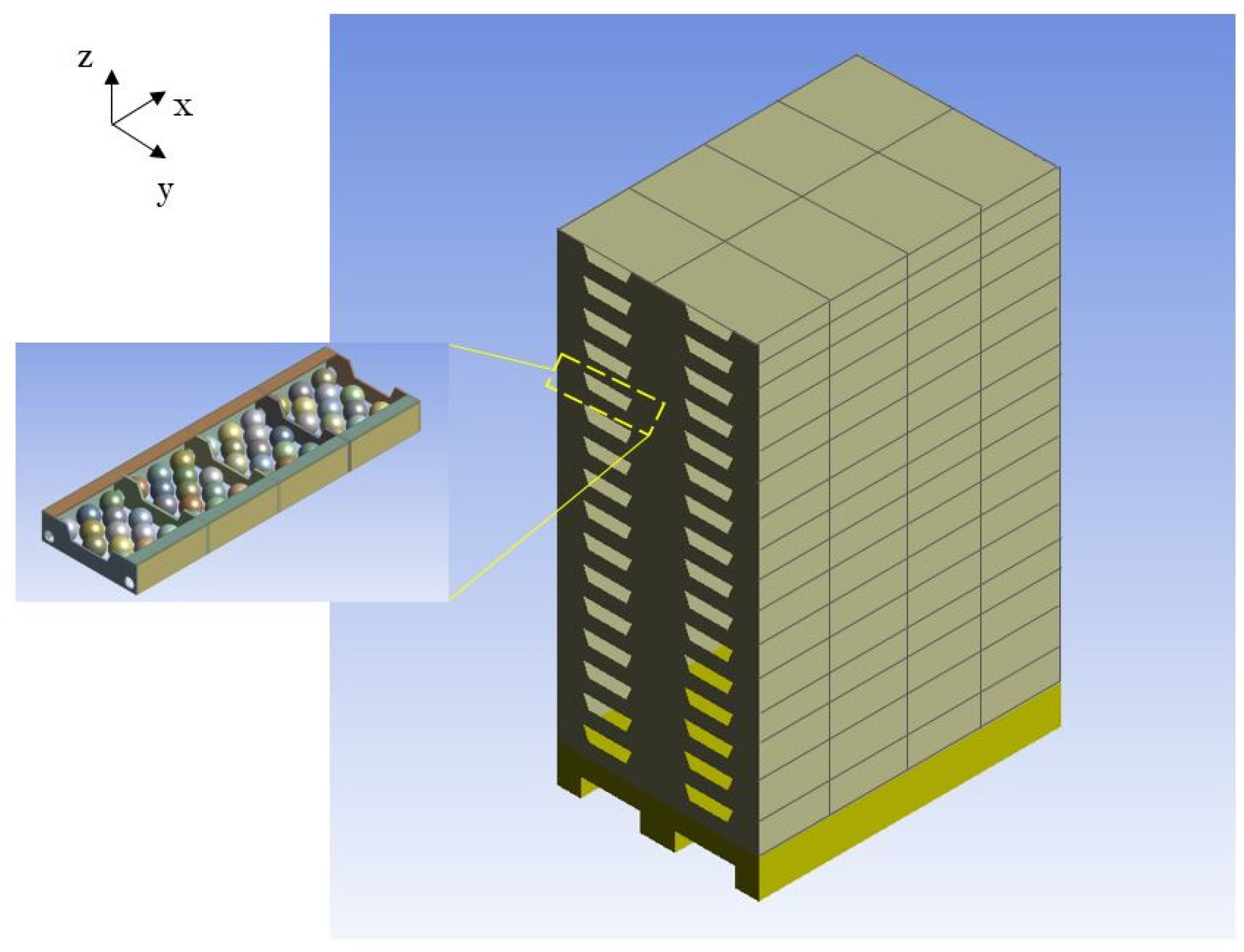
Figure 1. Current arrangement of a pallet of tomatoes (128 crates, 16 layers).
Energies 16 02048 g001
Figure 2. Illustration of the dimensions and the arrangement of the crates and carrageenan spheres.
Energies 16 02048 g002
Figure 3. Image of the LDV measuring device and the honeycomb at the inlet of the tunnel.
Energies 16 02048 g003
Figure 4. CFD model boundary conditions.
Energies 16 02048 g004
Figure 5. (a) Crate A; (b) crate B; (c) crate C.
Energies 16 02048 g005
Figure 6. Comparison between the average experimental temperature measurements with respect to time and the average corresponding temperatures obtained numerically for all of the cooled products (crate B).
Energies 16 02048 g006
Figure 7. Comparison between the average experimental temperature measurements with respect to time and the average corresponding temperatures obtained numerically for the products in individual crates (crate B).
Energies 16 02048 g007
Figure 8. Comparison between experimental and numerical temperatures of the products at half-cooling time for an airflow rate of 0.66 L s−1 kg−1 (crate B).
Energies 16 02048 g008
Figure 9. Velocity field of the airflow in the xy plane (crate A design): (a) ux at z = 85 mm; (b) ux at z = 75 mm; (c) uz at z = 37.5 mm; (d) illustration of the flow directions of ux and uz..
Energies 16 02048 g009
Figure 10. Influence of the airflow rate on the cooling kinetics of the products (crate B).
Energies 16 02048 g010
Figure 11. Influence of the airflow rate on the air velocity at the crate inlets (crate B).
Energies 16 02048 g011
Figure 12. Influence of the airflow rate on the air velocity field within the crates (crate B).
Energies 16 02048 g012
Figure 13. Influence of the airflow rate on the temperature uniformity of the products packed in the crates (crate B).
Energies 16 02048 g013
Figure 14. Influence of the airflow rate on (a) the maximum temperature difference and (b) the average temperature difference between the products at the pallet layer and crate levels (crate B).
Energies 16 02048 g014
Figure 15. Influence of crate design on the cooling kinetics of the products for a pressure drop of 4.5 Pa between the inlets and the outlets of the pallet layer.
Energies 16 02048 g015
Figure 16. Illustration of the velocity fields at the middle plane of the crates for different crate designs at a pressure drop of 4.5 Pa.
Energies 16 02048 g016
Figure 17. Influence of crate design on the temperature uniformity of the product at a pressure drop of 4.5 Pa at HCT.
Energies 16 02048 g017
Figure 18. Influence of crate design on (a) the maximum temperature difference and (b) the average temperature difference between the products at the pallet layer and crate levels.
Energies 16 02048 g018
Table 1. Thermophysical properties used for the heat transfer modelling.
PropertyCarrageenan Gel [26]PMMA [27]Air [27]
λ (W m−1 K−1)0.5190.20.0242
ρ (kg m−3]101314501.264 @ 6 °C
Cp (J kg−1 K−1)410011701006.43
µ (kg m−1 s−1)--1.7894 × 10⁻⁵
Table 2. Airflow parameters.
ΔP (Pa)u (m s−1)Q (L s−1 kg−1)
0.40.080.26
2.40.140.46
4.50.220.66
Table 3. Model prediction errors.
RMSE (°C)ARD (%)
Crate 10.442.35
Crate 20.624.20
Crate 30.715.50
Crate 40.262.05
Overall0.483.56
Table 4. Average air temperature in °C at the inlets of the 4 crates for different airflow rates.
0.26 L s−1 kg−10.46 L s−1 kg−10.66 L s−1 kg−1
Inlet crate 16.06.06.0
Inlet crate 29.18.68.0
Inlet crate 310.49.68.8
Inlet crate 412.110.49.4
Disclaimer/Publisher’s Note: The statements, opinions and data contained in all publications are solely those of the individual author(s) and contributor(s) and not of MDPI and/or the editor(s). MDPI and/or the editor(s) disclaim responsibility for any injury to people or property resulting from any ideas, methods, instructions or products referred to in the content.