
Solar Hot Water Systems Using Latent Heat Thermal Energy Storage: Perspectives and Challenges


Abstract
1. Introduction
2. Solar Hot Water Systems Using LHTES
2.1. Heat-Pipe-Assisted LHTES System
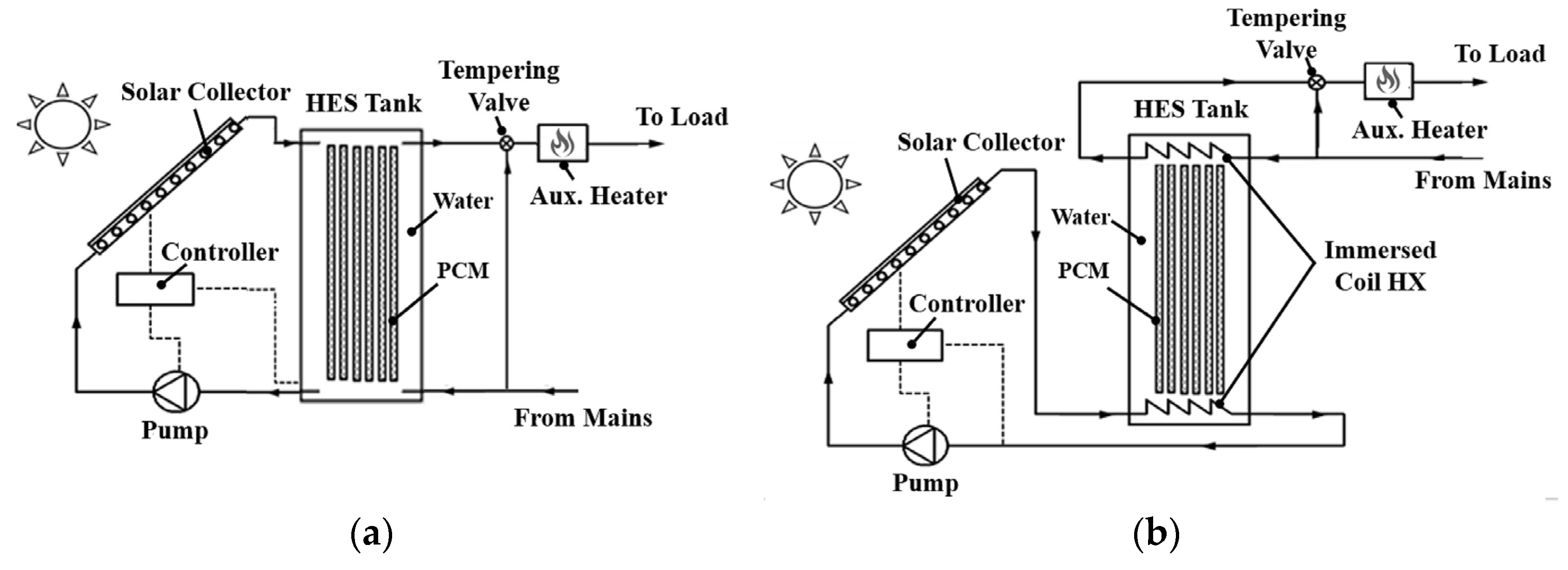
2.2. LHTES Modules Integrated into the Water Storage Tank
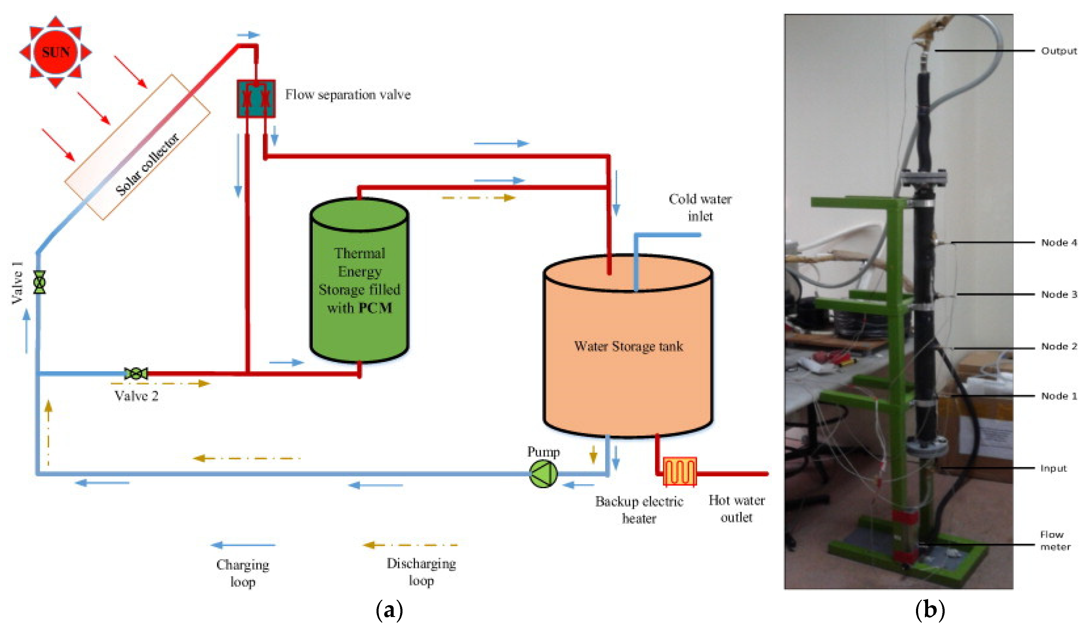
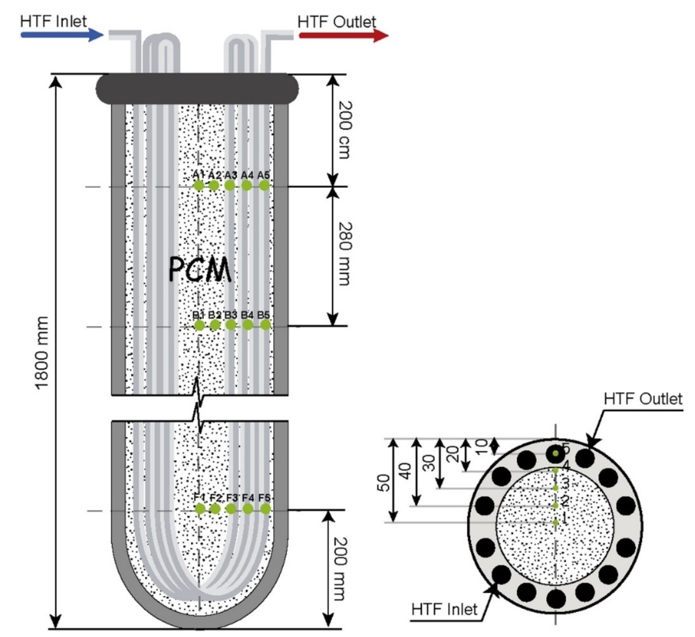
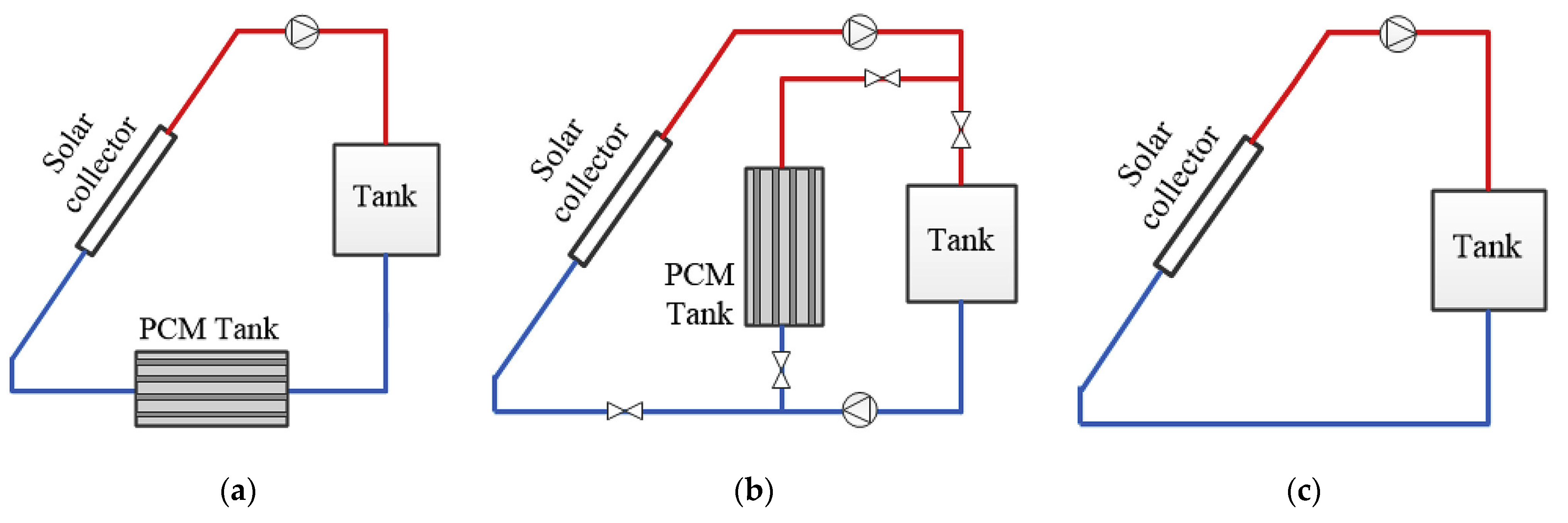
2.3. Water Storage Tank with a Separate LHTES
3. Current Research Activities (Last 5 Years)
4. Perspectives and Challenges
- (i)
- The heat-pipe-assisted LHTES system appears to be a promising solution for domestic hot water supply. Its ability to provide hot water at a temperature of 40–45 °C, at a flow rate of 50 L/h, for an extended period of 3 to 4 h, along with a thermal efficiency between 30% and 50%, and its ability to solve thermal stratification and overheat issues are significant advantages. Furthermore, replacing the conventional hot water tank also reduces the space requirement. These features make the system an attractive option for those looking to integrate sustainable energy solutions into their buildings. However, the high cost of the heat-pipe-based solar collector and a lack of experimental work to prove the system’s effectiveness and economics are challenges that need to be addressed. Further research and optimization studies are needed to justify the LHTES applicability and bring down the overall cost of the system.
- (ii)
- The second type of system, which utilizes LHTES modules inside a hot water tank, has the potential to maintain a temperature of 40–55 °C for extended periods, i.e., of 6 to 12 h. However, most studies have not accounted for the hot water withdrawal during the testing. As of now, there is no evidence to suggest that this type of system is superior to the first type, but it does exhibit higher thermal efficiency (50–70%), theoretically. While it cannot fully replace a conventional tank, it has the potential to reduce the size of the tank. One of the biggest challenges in implementing this type of system is the risk of PCM leakage from the small LHTES modules if not thermally cycled before use. Additionally, there are a variety of parameters that govern the system’s performance, such as the type of PCM, aspect ratio of the storage tank, position of PCM modules (top, medium, and bottom), storage tank volume, and the number of storage tanks, which make optimization a complex process. Therefore, more on-demand performance studies are needed to optimize hot water production and address the challenges associated with this type of system.
- (iii)
- The third type of system, which utilizes a separate LHTES tank, has not yet reached maturity. Studies have shown that these systems are currently unable to provide hot water at temperatures of 40 °C for even a short period (3–4 h). The major challenges are the formation of a solid layer around the inner tube of the heat exchanger during discharging and the low thermal conductivity of the PCM, which reduces the system’s ability to provide hot water at a desired temperature. In addition, the design, orientation, and position of the heat exchanger significantly affect the phase-changing phenomenon and impact the system’s performance. Hence, more research is needed to improve the heat transfer rate during energy storage and recovery, optimize the heat exchanger’s design, and find ways to increase the thermal conductivity of the PCM used in the system.
5. Conclusions and Future Work
Author Contributions
Funding
Data Availability Statement
Conflicts of Interest
Abbreviations
| CFD | computational fluid dynamics |
| ETHPSC | evacuated tube heat pipe solar collector |
| HTF | heat transfer fluid |
| LHTES | latent heat thermal energy storage |
| MEPCM | microencapsulated phase-change material |
| NEPCM | nano-enhanced phase-change material |
| PCM | phase-change material |
References
- Agyenim, F.; Hewitt, N.; Eames, P.; Smyth, M. A review of materials, heat transfer and phase change problem formulation for latent heat thermal energy storage systems (LHTESS). Renew. Sustain. Energy Rev. 2010, 14, 615–628. [Google Scholar] [CrossRef]
- Kalidasan, B.; Pandey, A.K.; Shahabuddin, S.; Samykano, M.; Thirugnanasambandam, M.; Saidur, E. Phase change materials integrated solar thermal energy systems: Global trends and current practices in experimental approaches. J. Energy Storage 2020, 27, 101118. [Google Scholar] [CrossRef]
- Fang, Y.; Niu, J.; Deng, S. Numerical analysis for maximizing effective energy storage capacity of thermal energy storage systems by enhancing heat transfer in PCM. Energy Build. 2018, 160, 10–18. [Google Scholar] [CrossRef]
- Chopra, K.; Tyagi, V.V.; Pathak, S.K.; Tripathi, P.A.; Sharma, R.K.; Singh, G.; Pandey, A.K. Thermal and chemical reliability of paraffin wax and its impact on thermal performance and economic analysis of solar water heater. Energy Sustain. Dev. 2023, 73, 39–53. [Google Scholar] [CrossRef]
- Bernal, D.C.; Muñoz, E.; Manente, G.; Sciacovelli, A.; Ameli, H.; Gallego-Schmid, A. Environmental assessment of latent heat thermal energy storage technology system with phase change material for domestic heating applications. Sustainability 2021, 13, 11265. [Google Scholar] [CrossRef]
- Shoeibi, S.; Kargarsharifabad, H.; Mirjalily, S.A.A.; Sadi, M.; Arabkoohsar, A. A comprehensive review of nano-enhanced phase change materials on solar energy applications. J. Energy Storage 2022, 50, 104262. [Google Scholar] [CrossRef]
- Eslami, M.; Khosravi, F.; Kohan, H.R.F. Effects of fin parameters on performance of latent heat thermal energy storage systems: A comprehensive review. Sustain. Energy Technol. Assess. 2021, 47, 101449. [Google Scholar] [CrossRef]
- Christopher, S.; Parham, K.; Mosaffa, A.; Farid, M.; Ma, Z.; Thakur, A.K.; Xu, H.; Saidur, R. A critical review on phase change material energy storage systems with cascaded configurations. J. Clean. Prod. 2021, 283, 124653. [Google Scholar] [CrossRef]
- Du, K.; Calautit, J.; Wang, Z.; Wu, Y.; Liu, H. A review of the applications of phase change materials in cooling, heating and power generation in different temperature ranges. Appl. Energy 2018, 220, 242–273. [Google Scholar] [CrossRef]
- Abhat, A. performance studies of a finned heat pipe latent thermal energy storage system. Sun Mankind’s Futur. Source Energy 1978, 1, 541–546. [Google Scholar] [CrossRef]
- Liu, Z.; Wang, Z.; Ma, C. An experimental study on the heat transfer characteristics of a heat pipe heat exchanger with latent heat storage. Part II: Simultaneous charging/discharging modes. Energy Convers. Manag. 2006, 47, 967–991. [Google Scholar] [CrossRef]
- Naghavi, M.S.; Silaakhori, M.; Mehrali, M.; Simon, H.; Metselaar, C.; Badruddin, I.A. Analytical thermal modeling of a heat pipe solar water heater system integrated with phase change material. Comput. Appl. Environ. Sci. Renew. Energy 2014, 1, 197–208. [Google Scholar]
- Lee, W.S.; Chen, B.R.; Chen, S.L. Latent heat storage in a two-phase thermosyphon solar water heater. J. Sol. Energy Eng. Trans. ASME 2006, 128, 69–76. [Google Scholar] [CrossRef]
- Naghavi, M.S.; Ong, K.S.; Badruddin, I.A.; Mehrali, M.; Silakhori, M.; Metselaar, H.S.C. Theoretical model of an evacuated tube heat pipe solar collector integrated with phase change material Theoretical model of an evacuated tube heat pipe solar collector integrated with phase change material. Energy 2015, 91, 911–924. [Google Scholar] [CrossRef]
- Brahim, T.; Houcine, M.; Jemni, A. Theoretical and experimental investigation of plate screen mesh heat pipe solar collector Theoretical and experimental investigation of plate screen mesh heat pipe solar collector. Energy Convers. Manag. 2014, 87, 428–438. [Google Scholar] [CrossRef]
- Tiari, S.; Qiu, S.; Mahdavi, M. Numerical study of finned heat pipe-assisted thermal energy storage system with high temperature phase change material. Energy Convers. Manag. 2015, 89, 833–842. [Google Scholar] [CrossRef]
- Robak, C.W.; Bergman, T.L.; Faghri, A. International Journal of Heat and Mass Transfer Enhancement of latent heat energy storage using embedded heat pipes. Int. J. Heat Mass Transf. 2011, 54, 3476–3484. [Google Scholar] [CrossRef]
- Bazri, S.; Badruddin, I.A.; Naghavi, M.S.; Seng, O.K.; Wongwises, S. An analytical and comparative study of the charging and discharging processes in a latent heat thermal storage tank for solar water heater system. Sol. Energy 2019, 185, 424–438. [Google Scholar] [CrossRef]
- Naghavi, M.S.; Ong, K.S.; Badruddin, I.A.; Mehrali, M.; Metselaar, H.S.C. Thermal performance of a compact design heat pipe solar collector with latent heat storage in charging/discharging modes. Energy 2017, 127, 101–115. [Google Scholar] [CrossRef]
- Naghavi, M.; Ang, B.; Rahmanian, B.; Naghavi, S.; Bazri, S.; Mahmoodian, R.; Metselaar, H. On-demand dynamic performance of a thermal battery in tankless domestic solar water heating in the tropical region. Appl. Therm. Eng. 2019, 167, 114790. [Google Scholar] [CrossRef]
- Papadimitratos, A.; Sobhansarbandi, S.; Pozdin, V. Evacuated tube solar collectors integrated with phase change materials. Sol. Energy 2016, 129, 10–19. [Google Scholar] [CrossRef]
- Pawar, V.R.; Sobhansarbandi, S. CFD modeling of a thermal energy storage based heat pipe evacuated tube solar collector. J. Energy Storage 2020, 30, 101528. [Google Scholar] [CrossRef]
- Wu, W.; Wang, X.; Xia, M.; Dou, Y.; Yin, Z.; Wang, J.; Lu, P. A novel composite PCM for seasonal thermal energy storage of solar water heating system. Renew. Energy 2020, 161, 457–469. [Google Scholar] [CrossRef]
- Xue, H.S. Experimental investigation of a domestic solar water heater with solar collector coupled phase-change energy storage. Renew. Energy 2016, 86, 257–261. [Google Scholar] [CrossRef]
- Canbazoğlu, S.; Abdulmuttalip, Ş.; Ahmet, E.; Gökhan, A.Ý.; Fatih, A. Enhancement of solar thermal energy storage performance using sodium thiosulfate pentahydrate of a conventional solar water-heating system. Energy Build. 2005, 37, 235–242. [Google Scholar] [CrossRef]
- Mazman, M.; Cabeza, L.F.; Mehling, H. Utilization of phase change materials in solar domestic hot water systems. Renew. Energy 2009, 34, 1639–1643. [Google Scholar] [CrossRef]
- Maaly, A.; Naqeera, I.A. Experimental investigation on the use of water-phase change material storage in conventional solar water heating systems. Energy Convers. Manag. 2010, 51, 1735–1740. [Google Scholar] [CrossRef]
- Wu, S.; Fang, G. Dynamic performances of solar heat storage system with packed bed using myristic acid as phase change material. Energy Build. 2011, 43, 1091–1096. [Google Scholar] [CrossRef]
- Fazilati, M.A.; Alemrajabi, A.A. Author’s personal copy Phase change material for enhancing solar water heater, an experimental approach. Energy Convers. Manag. 2013, 71, 138–145. [Google Scholar] [CrossRef]
- Navarro, L.; Barreneche, C.; Castell, A.; Redpath, D.A.G.; Grif, P.W.; Cabeza, L.F. High density polyethylene spheres with PCM for domestic hot water applications: Water tank and laboratory scale study. J. Energy Storage 2017, 13, 262–267. [Google Scholar] [CrossRef]
- Fang, Y.; Qu, Z.G.; Zhang, J.F.; Xu, H.T.; Qi, G.L. Charging performance of latent thermal energy storage system with microencapsulated phase-change material for domestic hot water. Energy Build. 2020, 224, 110237. [Google Scholar] [CrossRef]
- Nchelatebe, D.; Vouillamoz, P.; Haghighat, F.; El-mankibi, M.; Moreau, A.; Daoud, A. Impact of phase change materials types and positioning on hot water tank thermal performance: Using measured water demand profile. Appl. Therm. Eng. 2014, 67, 460–468. [Google Scholar] [CrossRef]
- Teamah, H.M.; Lightstone, M.F.; Cotton, J.S. An alternative approach for assessing the bene fi t of phase change materials in solar domestic hot water systems. Sol. Energy 2017, 158, 875–888. [Google Scholar] [CrossRef]
- Teamah, H.M.; Lightstone, M.F.; Cotton, J.S. Potential of cascaded phase change materials in enhancing the performance of solar domestic hot water systems. Sol. Energy 2018, 159, 519–530. [Google Scholar] [CrossRef]
- Afshan, M.E.; Selvakumar, A.S.; Velraj, R.; Rajaraman, R. Effect of aspect ratio and dispersed PCM balls on the charging performance of a Latent heat thermal storage unit for solar thermal applications. Renew. Energy 2019, 148, 876–888. [Google Scholar] [CrossRef]
- Bayomy, A.; Davies, S.; Saghir, Z. Domestic hot water storage tank utilizing phase change materials (PCMs): Numerical approach. Energies 2019, 12, 2170. [Google Scholar] [CrossRef]
- Elbahjaoui, R.; El Qarnia, H. Thermal performance of a solar latent heat storage unit using rectangular slabs of phase change material for domestic water heating purposes. Energy Build. 2018, 224, 110237. [Google Scholar] [CrossRef]
- Abdelsalam, M.Y.; Teamah, H.M.; Lightstone, M.F.; Cotton, J.S. Hybrid thermal energy storage with phase change materials for solar domestic hot water applications: Direct versus indirect heat exchange systems. Renew. Energy 2020, 147, 77–88. [Google Scholar] [CrossRef]
- Sinem, K.; El, E.; Cengiz, Y. Investigation of the effect on the efficiency of phase change material placed in solar collector tank. Therm. Sci. Eng. Prog. 2018, 5, 25–31. [Google Scholar] [CrossRef]
- Kousksou, T.; Bruel, P.; Cherreau, G.; Leoussoff, V.; El Rhafiki, T. PCM storage for solar DHW: From an unfulfilled promise to a real benefit. Sol. Energy 2011, 85, 2033–2040. [Google Scholar] [CrossRef]
- Talmatsky, E.; Kribus, A. PCM storage for solar DHW: An unfulfilled promise? Sol. Energy 2008, 82, 861–869. [Google Scholar] [CrossRef]
- De Gracia, A.; Oró, E.; Farid, M.M.; Cabeza, L.F. Thermal analysis of including phase change material in a domestic hot water cylinder. Appl. Therm. Eng. 2011, 31, 3938–3945. [Google Scholar] [CrossRef]
- Farid, M.; Richard, S. New hot water cylinder incorporation phase change heat storage. In Proceedings of the APCCHE2002, Christchurch, New Zealand, 29 September–3 October 2002. [Google Scholar]
- Mahfuz, M.H.; Anisur, M.R.; Kibria, M.A.; Saidur, R.; Metselaar, I.H.S.C. Performance investigation of thermal energy storage system with Phase Change Material (PCM) for solar water heating application. Int. Commun. Heat Mass Transf. 2014, 57, 132–139. [Google Scholar] [CrossRef]
- Luu, M.T.; Milani, D.; Nomvar, M.; Abbas, A. Dynamic modelling and analysis of a novel latent heat battery in tankless domestic solar water heating. Energy Build. 2017, 152, 227–242. [Google Scholar] [CrossRef]
- Luu, M.T.; Milani, D.; Nomvar, M.; Abbas, A. A design protocol for enhanced discharge exergy in phase change material heat battery. Appl. Energy 2020, 265, 114801. [Google Scholar] [CrossRef]
- Lamrani, B.; Kuznik, F.; Draoui, A. Thermal performance of a coupled solar parabolic trough collector latent heat storage unit for solar water heating in large buildings. Renew. Energy 2020, 162, 411–426. [Google Scholar] [CrossRef]
- Lu, B.; Zhang, Y.; Sun, D.; Yuan, Z.; Yang, S. Experimental investigation on thermal behavior of paraffin in a vertical shell and spiral fin tube latent heat thermal energy storage unit. Appl. Therm. Eng. 2021, 187, 116575. [Google Scholar] [CrossRef]
- Gao, Y.; He, F.; Xu, T.; Meng, X.; Zhang, M.; Yan, L.; Gao, W. Thermal performance analysis of sensible and latent heat thermal energy storage tanks: A contrastive experiment. J. Build. Eng. 2020, 32, 101713. [Google Scholar] [CrossRef]
- Dogkas, G.; Konstantaras, J.; Koukou, M.K.; Vrachopoulos, M.G.; Pagkalos, C.; Stathopoulos, V.N.; Pandis, P.K.; Lymperis, K.; Coelho, L.; Rebola, A. Development and experimental testing of a compact thermal energy storage tank using paraffin targeting domestic hot water production needs. Therm. Sci. Eng. Prog. 2020, 19, 100573. [Google Scholar] [CrossRef]
- Osman, M.; Abokersh, M.H.; Sharaf, O.; Mahmoud, N. Key performance indicators (KPIs): Assessing the process integration of a shell-and-tube latent heat storage unit. J. Clean. Prod. 2020, 256, 120249. [Google Scholar] [CrossRef]
- Huang, H.; Xiao, Y.; Lin, J.; Zhou, T.; Liu, Y.; Zhao, Q. Improvement of the efficiency of solar thermal energy storage systems by cascading a PCM unit with a water tank. J. Clean. Prod. 2019, 245, 118864. [Google Scholar] [CrossRef]
- Shalaby, S.M.; Kabeel, A.E.; Moharram, B.M.; Flea, A.H. Experimental study of the solar water heater integrated with shell and fi nned tube latent heat storage system. J. Energy Storage 2020, 47, 103588. [Google Scholar] [CrossRef]
- Liu, W.; Bie, Y.; Xu, T.; Cichon, A.; Królczyk, G.; Li, Z. Heat transfer enhancement of latent heat thermal energy storage in solar heating system: A state-of-the-art review. J. Energy Storage 2022, 46, 103727. [Google Scholar] [CrossRef]
- Fadl, M.; Eames, P.C. An experimental investigation of the heat transfer and energy storage characteristics of a compact latent heat thermal energy storage system for domestic hot water applications. Energy 2019, 188, 121262. [Google Scholar] [CrossRef]
- Larrinaga, P.; Diarce, G.; Campos-Celador, Á.; García-Romero, A. Parametric characterization of a full-scale plate-based latent heat thermal energy storage system. Appl. Therm. Eng. 2020, 178, 115441. [Google Scholar] [CrossRef]
- Koukou, M.K.; Vrachopoulos, M.G.; Tachos, N.S.; Dogkas, G.; Lymperis, K.; Stathopoulos, V. Experimental and computational investigation of a latent heat energy storage system with a staggered heat exchanger for various phase change materials. Therm. Sci. Eng. Prog. 2018, 7, 87–98. [Google Scholar] [CrossRef]
- Kumar, J.; Singh, P.; Kumar, R. The Effect of Geometric Parameters of a Container on Thermal Charging of Latent Heat Thermal Energy Storage System: A Review. In Lecture Notes in Mechanical Engineering; Springer: Singapore, 2022; pp. 1185–1195. [Google Scholar]
- Sorour, M.M.; Hassab, M.A.; Zaytoun, M.M.; Alnakeeb, M.A. The effect of inclination angle on the performance characteristic of a double-pipe latent heat storage unit. J. Energy Storage 2021, 34, 102202. [Google Scholar] [CrossRef]
- Kalapala, L.; Devanuri, J.K. Effect of orientation on thermal performance of a latent heat storage system equipped with annular fins—An experimental and numerical investigation. Appl. Therm. Eng. 2021, 183, 116244. [Google Scholar] [CrossRef]
- Ma, X.; Zhang, Q.; Wang, J.; Yue, C. Sensitivity analysis and optimization of structural parameters of a phase change material based multi-tube heat exchanger under charging condition. J. Energy Storage 2022, 56, 105940. [Google Scholar] [CrossRef]
- Modi, N.; Wang, X.; Negnevitsky, M. Melting and solidification characteristics of a semi-rotational eccentric tube horizontal latent heat thermal energy storage. Appl. Therm. Eng. 2022, 214, 118812. [Google Scholar] [CrossRef]
- Tofani, K.; Tiari, S. Nano-enhanced phase change materials in latent heat thermal energy storage systems: A review. Energies 2021, 14, 3821. [Google Scholar] [CrossRef]
- Wołoszyn, J.; Szopa, K.; Czerwiński, G. Enhanced heat transfer in a PCM shell-and-tube thermal energy storage system. Appl. Therm. Eng. 2021, 196, 117332. [Google Scholar] [CrossRef]
- Punniakodi, B.M.S.; Senthil, R. Enhanced heat transfer in a phase change energy storage with helical tubes. J. Energy Storage 2023, 58, 106352. [Google Scholar] [CrossRef]
- Zhu, X.; Li, Y.; Zhu, Q. Heat transfer enhancement technology for fins in phase change energy storage. J. Energy Storage 2022, 55, 105833. [Google Scholar] [CrossRef]
- Mohammadpour, J.; Lee, A.; Timchenko, V.; Taylor, R. Nano-Enhanced Phase Change Materials for Thermal Energy Storage: A Bibliometric Analysis. Energies 2022, 15, 3426. [Google Scholar] [CrossRef]
- Amin, M.; Putra, N.; Kosasih, E.A.; Prawiro, E.; Luanto, R.A.; Mahlia, T.M.I. Thermal properties of beeswax/graphene phase change material as energy storage for building applications. Appl. Therm. Eng. 2016, 112, 273–280. [Google Scholar] [CrossRef]
- Abdulateef, A.M.; Mat, S.; Abdulateef, J.; Sopian, K. Geometric and design parameters of fi ns employed for enhancing thermal energy storage systems: A review. Renew. Sustain. Energy Rev. 2018, 82, 1620–1635. [Google Scholar] [CrossRef]
- Modi, N.; Wang, X.; Negnevitsky, M.; Cao, F. Melting characteristics of a longitudinally finned-tube horizontal latent heat thermal energy storage system. Sol. Energy 2021, 230, 333–344. [Google Scholar] [CrossRef]
- Kumar, R.; Verma, P. An experimental and numerical study on effect of longitudinal finned tube eccentric configuration on melting behaviour of lauric acid in a horizontal tube-in-shell storage unit. J. Energy Storage 2020, 30, 101396. [Google Scholar] [CrossRef]
- Patel, J.R.; Rathod, M.K.; Sheremet, M. Heat transfer augmentation of triplex type latent heat thermal energy storage using combined eccentricity and longitudinal fin. J. Energy Storage 2022, 50, 104167. [Google Scholar] [CrossRef]
- Ge, R.; Li, Q.; Li, C.; Liu, Q. Evaluation of different melting performance enhancement structures in a shell-and-tube latent heat thermal energy storage system. Renew. Energy 2022, 187, 829–843. [Google Scholar] [CrossRef]
- Arıcı, M.; Kamal, A.; Teggar, M.; Ajarostaghi, S.S.M. Performance enhancement of latent heat storage systems by using extended surfaces and porous materials: A state-of-the-art review. J. Energy Storage 2021, 44, 103340. [Google Scholar] [CrossRef]
- Soltani, H.; Soltani, M.; Karimi, H.; Nathwani, J. Heat transfer enhancement in latent heat thermal energy storage unit using a combination of fins and rotational mechanisms. Int. J. Heat Mass Transf. 2021, 179, 121667. [Google Scholar] [CrossRef]
- Soltani, H.; Soltani, M.; Karimi, H.; Nathwani, J. Optimization of shell and tube thermal energy storage unit based on the effects of adding fins, nanoparticles and rotational mechanism. J. Clean. Prod. 2022, 331, 129922. [Google Scholar] [CrossRef]
- Pizzolato, A.; Sharma, A.; Maute, K.; Sciacovelli, A.; Verda, V. Design of effective fins for fast PCM melting and solidification in shell-and-tube latent heat thermal energy storage through topology optimization. Appl. Energy 2017, 208, 210–227. [Google Scholar] [CrossRef]
- Irfan, M.; Mahabat, M.; Asip, L.; Farooq, H. Melting performance enhancement of a phase change material using branched fins and nanoparticles for energy storage applications. J. Energy Storage 2021, 38, 102513. [Google Scholar] [CrossRef]
- Yao, S.; Huang, X. Study on solidification performance of PCM by longitudinal triangular fins in a triplex-tube thermal energy storage system. Energy 2021, 227, 120527. [Google Scholar] [CrossRef]
- Ma, J.; Xu, H.; Liu, S.; Peng, H.; Ling, X. International Journal of Heat and Mass Transfer Numerical study on solidification behavior and exergy analysis of a latent heat storage unit with innovative circular superimposed longitudinal fins. Int. J. Heat Mass Transf. 2021, 169, 120949. [Google Scholar] [CrossRef]
- Ren, F.; Du, J.; Cai, Y.; Guo, J.; Liu, Y.; Zhang, D.; Li, M. Study on thermal performance of a new optimized snowflake longitudinal fin in vertical latent heat storage. J. Energy Storage 2022, 50, 104165. [Google Scholar] [CrossRef]
- Huang, Y.; Liu, X. Charging and discharging enhancement of a vertical latent heat storage unit by fractal tree-shaped fins. Renew. Energy 2021, 174, 199–217. [Google Scholar] [CrossRef]
- Elmaazouzi, Z.; Ait, I.; Gounni, A.; El, M.; Outzourhit, A.; Ghali, E. Coupled parameters evaluation of three different finned structures for concentrated solar thermal energy storage. J. Energy Storage 2022, 51, 104523. [Google Scholar] [CrossRef]
- Ding, P.; Liu, Z. International Journal of Thermal Sciences Numerical investigation of natural convection enhancement in latent heat energy storage units with punched-fin and slit-fin. Int. J. Therm. Sci. 2021, 163, 106834. [Google Scholar] [CrossRef]
- Nicholls, R.A.; Moghimi, M.A.; Griffiths, A.L. Impact of fin type and orientation on performance of phase change material-based double pipe thermal energy storage. J. Energy Storage 2022, 50, 104671. [Google Scholar] [CrossRef]
- Saini, P.; Dhar, A.; Powar, S. Parametric optimization of a cesaro fins employed latent heat storage system for melting performance enhancement. J. Energy Storage 2022, 51, 104534. [Google Scholar] [CrossRef]


| Reference | Examined System/Scope of the Study | Type of Study | Observations |
|---|---|---|---|
| Abhat [10] | A finned-heat-pipe-assisted LHTES system. | Experimental | The system was able to operate within smaller temperature gradients (<10 °C). |
| Liu et al. [11] | A heat-pipe heat exchanger with latent heat storage. | Experimental | The system was able to perform simultaneous charging/discharging for the continuous operation of the system. |
| Naghavi et al. [12] | The ETHPSC assisted LHTES system. | Numerical | The system was able to control the overloading of the heat pipe and prevent overheating of the water supply during peak solar radiation hours. |
| Lee et al. [13] | A two-phase closed thermosyphon system with LHTES. | Experimental | The usage of PCM could make the storage tank lighter than traditional heating systems. |
| Brahim et al. [15] | A plate-screen-meshes-heat-pipe-assisted solar water heater. | Numerical and Experimental | It achieved a collector efficiency of 60% by adding fins to the condenser region of the heat pipes. |
| Tiari et al. [16] | A finned-heat-pipe-assisted LHTES system. | Numerical | An increasing number of heat pipes improved the thermal performance by increasing the melting rate. |
| Robak et al. [17] | Different combinations of the heat pipe and fins in the LHTES system. | Experimental | Fins were not as effective as heat pipes in improving thermal performance. |
| Naghavi et al. [14] | The ETHPSC-assisted LHTES system. | Numerical | Extended the operating time for 3 to 4 h with an outlet water temperature of 39 °C. |
| Bazri et al. [18] | The ETHPSC-assisted LHTES system. | Numerical | The system was able to provide hot water at a temperature of 46 °C for 4 h, with a flow rate of 50 L/h. |
| Naghavi et al. [19] | The ETHPSC-assisted LHTES system. | Experimental | It achieved a thermal efficiency of 38–42% on sunny days and 34–36% on cloudy/rainy days. |
| Naghavi et al. [20] | On-demand performance study of the ETHPSC-assisted LHTES system. | Experimental | The system was able to deliver a minimum of 112–170 L of hot water per day in the worst weather conditions. |
| Reference | Examined System/Scope of the Study | Type of Study | Observations |
|---|---|---|---|
| Canbazoğlu et al. [25] | Placed cylindrical LHTES modules inside the hot water tank. | Experimental | The water temperature remained constant at 45 °C for approximately 10 h after the solar radiation decreased. |
| Mazman et al. [26] | Added cylindrical-shaped PCM units at the top of the storage tank. | Experimental | It achieved a thermal efficiency of 74%. During discharge, the average temperature of the storage tank dropped below the PCM melting temperature range (49–53 °C) within 6–12 h. |
| Al-Hinti et al. [27] | Placed the PCM-filled aluminium bottles inside the hot water tank. | Experimental | The water temperature was maintained at 13–14 °C higher than the system without PCM. |
| Fazilati and Alemrajabi [29] | Utilized PCM-contained spherical capsules in the jacketed shell-type storage tank. | Experimental | The system was able to supply hot water at a specified temperature for a 25% longer time. |
| Fang et al. [31] | Designed a MEPCM-based LHTES system. | Experimental | The system exhibited a stable operation and a high heat transfer rate, indicating that it is practical for use in domestic hot water systems. |
| Nkwetta et al. [32] | Studied different positions of PCM inside the storage tank. | Numerical | The top position of the PCM was better than the middle position. |
| Teamah et al. [34] | Studied the combination of different storage tanks with different PCMs. | Numerical | The storage tank volume was reduced by more than 50% by using multiple hybrid storage tanks. |
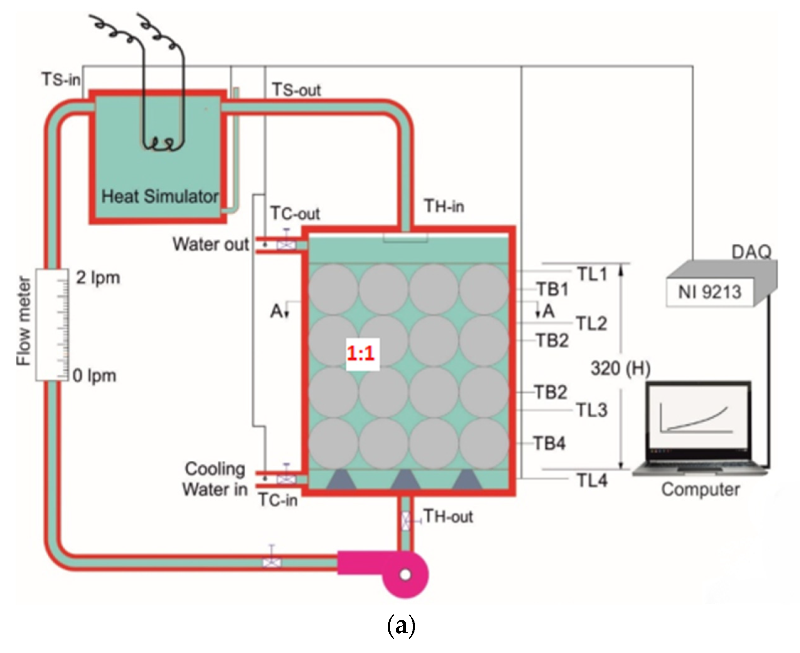
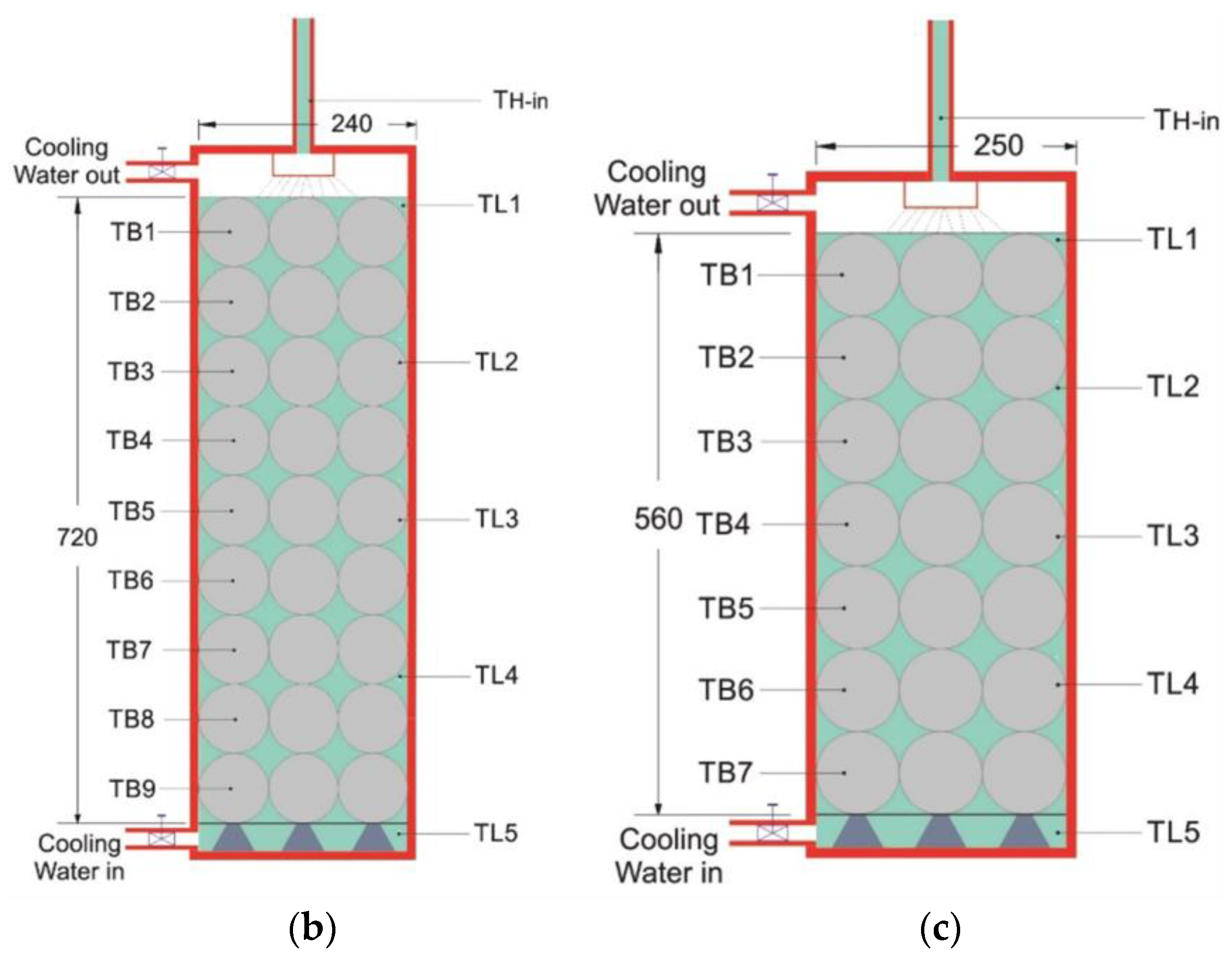
| Afshan et al. [35] | Studied different aspect ratios of the hybrid water storage tank. | Experimental | A lower aspect ratio (1:1) was recommended for hybrid thermal storage with PCM spheres. |
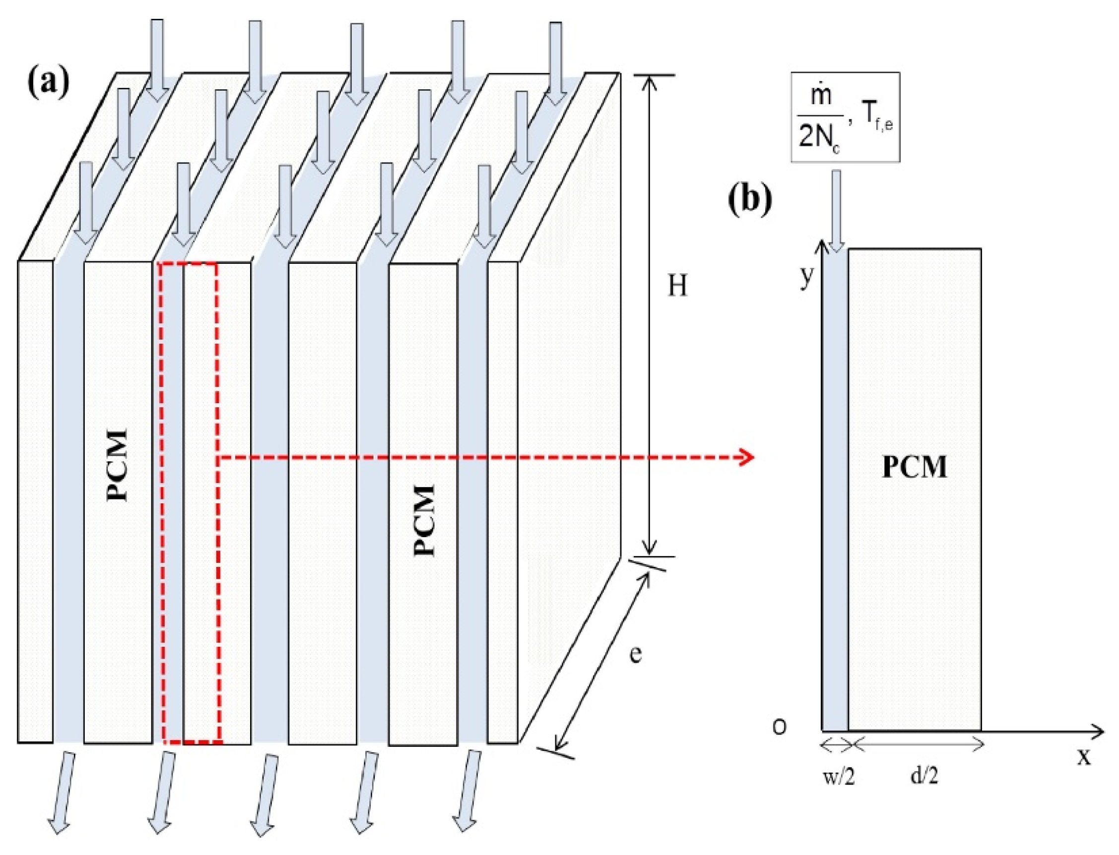
| Elbahjaoui and Qarnia [37] | Rectangular-shaped LHTES with different PCMs. | Numerical | The outlet water temperature was observed in the range of 43.6–24 °C, 51.7–24 °C, and 62.86–24 °C, respectively, for RT42, RT50, and RT60 during discharging. |
| Kılıçkap et al. [39] | The PCM was filled inside the annulus of the hot water tank. | Experimental | It achieved the highest thermal efficiency of 58% by using PCM. Moreover, the system with PCM was able to transfer stored heat to water at night, providing hot water for an additional 1–1.5 h. |
| Reference | Examined System/Scope of the Study | Type of Study | Observations |
|---|---|---|---|
| Mahfuz et al. [44] | A shell-and-tube heat exchanger as a separate LHTES system. | Experimental | For the lowest flow rate (0.033 L/min), the outlet water temperature remained above 40 °C for just 30 min. |
| Luu et al. [45] | A shell-and-tube-type tankless latent heat battery. | Numerical | Improved the fossil fuel saving by 15.7% more than a conventional system. |
| Luu et al. [46] | A shell-and-tube-type tankless latent heat battery. | Numerical | Achieved the discharge average temperature of 40 °C. |
| Lamrani et al. [47] | Parabolic-trough-collector-assisted rectangular shell-and-tube-type separate LHTES system. | Numerical | The PCM with a low melting temperature was unable to provide hot water at the desired temperature, while a PCM with a high melting temperature was not able to fully utilize available solar energy for storage. |
| Lu et al. [48] | A spiral-finned heat-exchanger-type separate LHTES system. | Experimental | The system has provided hot water of 40 °C with a flow rate of 0.5 L/min for just 2000 s (0.55 h). |
| Gao et al. [49] | A tube-in-tank-type separate LHTES system. | Experimental | The system was able to provide hot water of 40 °C with a flow rate of 0.6 L/min for just 19.3 min. |
| Dogkas et al. [50] | A staggered finned heat exchanger as a separate LHTES system. | Experimental | The system was able to produce 106 L of hot water instantly at a temperature above 40 °C during discharging. |
| Osman et al. [51] | A multi-tube heat exchanger as a separate LHTES system. | Numerical and Experimental | The LHTES unit was able to increase hot water temperature by 7–12 °C and maintained a constant hot water supply for extended periods of about 2–3 h. |
| Shalaby et al. [53] | Rectangular shell-and-finned tube-bank-type heat exchanger as a separate LHTES system. | Experimental | The configuration was able to provide hot water at a consistent temperature range of 50–60.4 °C for 24 h. |
Disclaimer/Publisher’s Note: The statements, opinions and data contained in all publications are solely those of the individual author(s) and contributor(s) and not of MDPI and/or the editor(s). MDPI and/or the editor(s) disclaim responsibility for any injury to people or property resulting from any ideas, methods, instructions or products referred to in the content. |
© 2023 by the authors. Licensee MDPI, Basel, Switzerland. This article is an open access article distributed under the terms and conditions of the Creative Commons Attribution (CC BY) license (https://creativecommons.org/licenses/by/4.0/).
Share and Cite
Modi, N.; Wang, X.; Negnevitsky, M. Solar Hot Water Systems Using Latent Heat Thermal Energy Storage: Perspectives and Challenges. Energies 2023, 16, 1969. https://doi.org/10.3390/en16041969
Modi N, Wang X, Negnevitsky M. Solar Hot Water Systems Using Latent Heat Thermal Energy Storage: Perspectives and Challenges. Energies. 2023; 16(4):1969. https://doi.org/10.3390/en16041969
Chicago/Turabian StyleModi, Nishant, Xiaolin Wang, and Michael Negnevitsky. 2023. "Solar Hot Water Systems Using Latent Heat Thermal Energy Storage: Perspectives and Challenges" Energies 16, no. 4: 1969. https://doi.org/10.3390/en16041969
APA StyleModi, N., Wang, X., & Negnevitsky, M. (2023). Solar Hot Water Systems Using Latent Heat Thermal Energy Storage: Perspectives and Challenges. Energies, 16(4), 1969. https://doi.org/10.3390/en16041969