Article

The Structural and Electromagnetic Comparative Analysis of the Bifilar-Meander-Type Winding Method of Superconducting DC Circuit Breaker

Department of Electrical Engineering, Chosun University, Gwangju 61452, Republic of Korea
*
Author to whom correspondence should be addressed.
Energies 2023, 16(4), 1866; https://doi.org/10.3390/en16041866
Submission received: 30 November 2022 / Revised: 6 February 2023 / Accepted: 9 February 2023 / Published: 13 February 2023

Abstract

:
As the utilization of DC systems increases worldwide, the importance of DC cutoff technology is increasing. We proposed a hybrid DC cutoff technology combining an SFCL (superconducting fault-current-limiter) and a mechanical DC circuit breaker. This model can perform a fault-current-limiting operation through the quenching of the SFCL and a breaking operation through an artificial cutoff zero point of a mechanical DC circuit breaker. In particular, the SFCL is responsible for the growth of the initial fault current according to the DC characteristics. As the DC system’s supply and demand increase, the DC system’s capacity also increases. Therefore, the fault-current-limiting capability of the SFCL should be increased according to the increasing DC system breaking capacity. The fault-current-limiting capability can be increased by increasing the superconducting wires used in the SFCL. Current commercially available SFCLs use bifilar-helical-type and bifilar-spiral-type winding methods. These have the disadvantage of increased volume with increased capacity. To compensate for these disadvantages, we proposed a bifilar-meander-type winding method. In this paper, a new bifilar-meander-type winding method was introduced. In addition, the structural and electromagnetic parts of the existing winding method and the bifilar-meander-type winding method were compared and analyzed for differences. The program used for this analysis is the electromagnetic analysis Maxwell program. As a result, it was confirmed that the bifilar-meander-type winding method is superior to the conventional bifilar-helical and bifilar-spiral types.

1. Introduction

1.1. Background

The scope of the application of DC systems is expanding with the spread of renewable energy and the increasing demand for digital loads [1]. Accordingly, the breaking capacity of the line in the DC system increases, and the fault current generated in the transient state also increases. We need a technology that can effectively cut off the rising fault current. Currently, power semiconductors are used as a cutoff technology for DC systems [2,3,4]. The disadvantages of power semiconductors are that they are very vulnerable to the heat generated in normal times and mechanical and electrical shocks. In addition, they have difficulty in commercialization due to their high price. We are researching a cutoff technology that can replace power semiconductors with the above disadvantages [5]. We are working on a hybrid-type DC circuit breaker combining an SFCL (superconducting fault-current-limiter) and a mechanical DC circuit breaker [6,7,8,9,10]. The SFCL can reduce the DC initial fault current by quenching within 2 ms. In addition, since it exhibits superconducting properties in the steady state of the line, no heat is generated. The downside is that the superconductor has to bear all the power burden until the DC fault current disappears. The mechanical DC circuit breaker has the advantage of being able to perform a stable cutoff operation because it can create an artificial cutting-off zero point of the LC divergence oscillation circuit [11]. Disadvantages are that the cutoff operation is slow compared to solid-state switches, and the opening operation is performed at high fault current levels, which is very dangerous. Combining the SFCL and the mechanical DC circuit breaker compensates for each other’s shortcomings [5,8,9,10].

1.2. Research Scope

This model can flexibly respond to the increasing capacity of the DC system with only the SFCL. Therefore, a new idea was needed to improve the capacity of the SFCL. The SFCL must have a cooling device, so the smaller and simpler the structure of the winding type, the better the efficiency. However, the impedance should be low due to the effect of the electric field generated between the wires of the SFCL. We propose a new winding method of the meander method by applying the bifilar method. The bifilar method is a technique of designing superconducting wires close to each other so that the current directions are opposite by winding them in opposite directions [12,13,14,15]. It has a magnetic property in which the magnetic field generated in each superconducting wire is oppositely generated and canceled. The purpose of the new bifilar-meander method proposed by us is to use as many superconducting wires as possible in a given space and to prevent a high increase in impedance between superconducting wires. This new bifilar-meander method is an easy way to design SFCL modules and can maximize space efficiency. To review this, the helical and spiral types to which the existing bifilar method was applied were compared and analyzed [15,16,17,18].
Structural and electromagnetic analysis were sequentially performed in this paper using Maxwell, an electromagnetic field analysis program. Structural analysis was modeled based on the same volume, and the amount of superconducting wire used was compared and analyzed according to the winding method of the superconducting wire. The electromagnetic analysis compared and analyzed the magnetic field between superconducting wires generated by each winding method.

2. The Winding Types for the Modules of the Superconducting Fault-Current-Limiter

Various winding methods such as helical, spiral, and meander types have been proposed for superconducting wires, and research on improved superconducting properties and quench properties is still ongoing [16,17,18,19]. In this regard, a bifilar method (a winding method in which two windings are designed in parallel and the current flow is reversed to reduce the inductance generated between the wires) is applied so that a pure resistive superconducting module can be designed. Compared to inductive superconducting modules, resistive superconducting modules can respond to the rapid growth of the DC fault current through the quench phenomenon and can improve the current limiting rate by increasing the amount of superconducting wire used. However, suppose the number of superconducting wires increases, and a certain distance between the wires is not secured. In that case, the superconducting wires are overheated due to heat dissipation energy during quenching. Accordingly, a major failure may occur due to disconnection or a short circuit of the superconducting wire. Therefore, the winding method and design of the superconducting wire in the cooling system are very important. In this paper, the differences in the winding methods of each superconducting wire were compared through the Maxwell program to manufacture a resistive superconducting module. The efficiency and generation impedance of each winding method superconducting wire were compared and analyzed through the standard box.
The helical method, called the solenoid coil, is designed by winding superconducting wire around a cylindrical tube. This method has a disadvantage in that the volume of the cooling system is larger than that of other winding methods because the wire rod is wound around the cylinder’s axis. Figure 1a shows the design of one superconducting wire. Figure 1b is a form in which two superconducting wires are designed applying the bifilar method, and the direction of the current flowing through each wire is opposite.
Figure 2 is a spiral type, also called a pancake coil. Figure 2a is designed with one superconducting wire from the outside. In Figure 2b, the bifilar method is applied to the superconducting wire, and two wires with different current flows are designed side by side.
Figure 3 shows a superconducting wire’s winding cross-section using the meander method. In Figure 3a, superconducting wires are designed according to our proposed meander type, and although they are designed as a single structure, two wires with different current flows are designed side by side. Figure 3b is an improved meander-type model in Figure 3a by adding one more wire, and it has the advantage of minimizing the impedance generated in the superconducting wire.

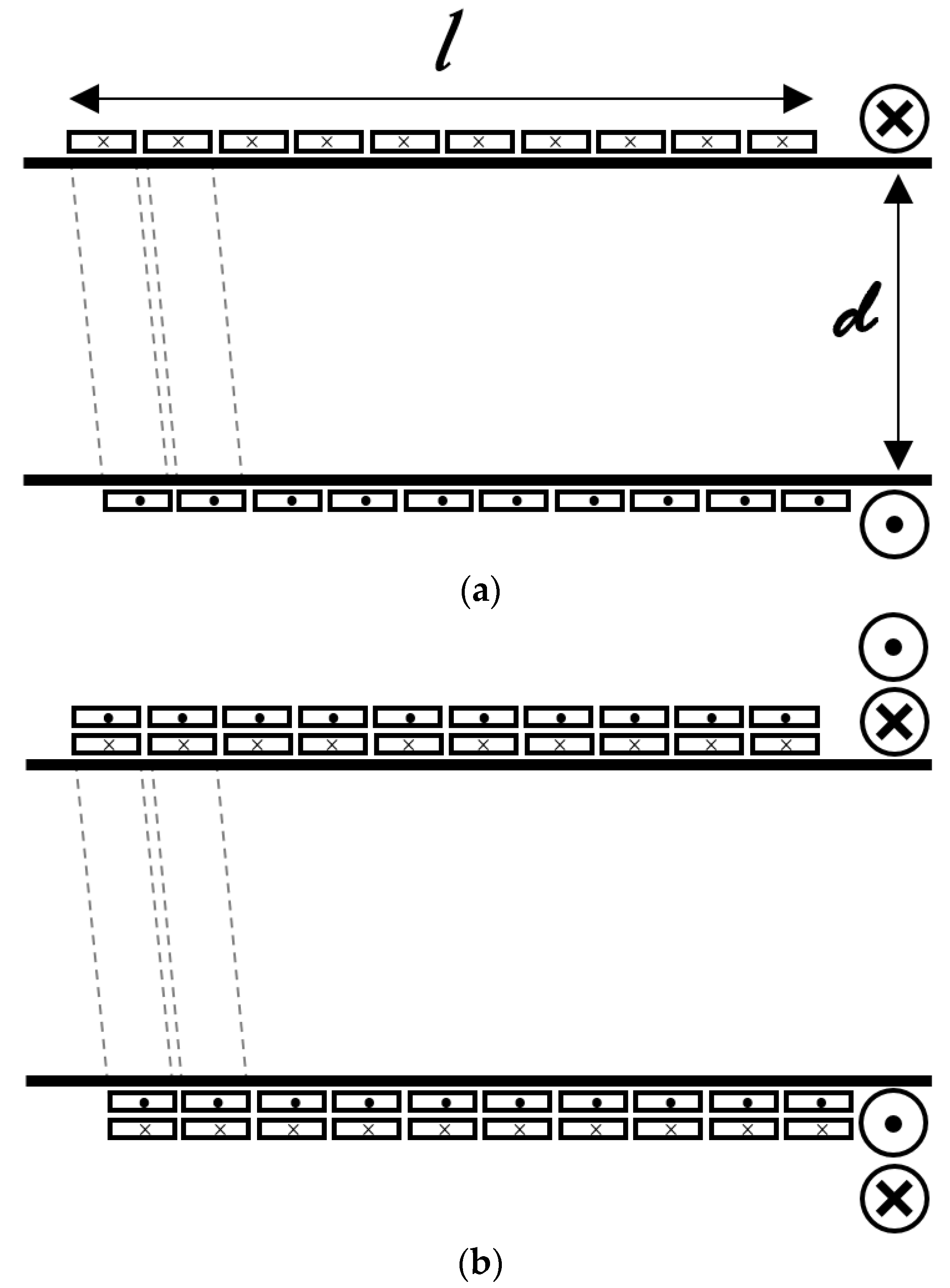
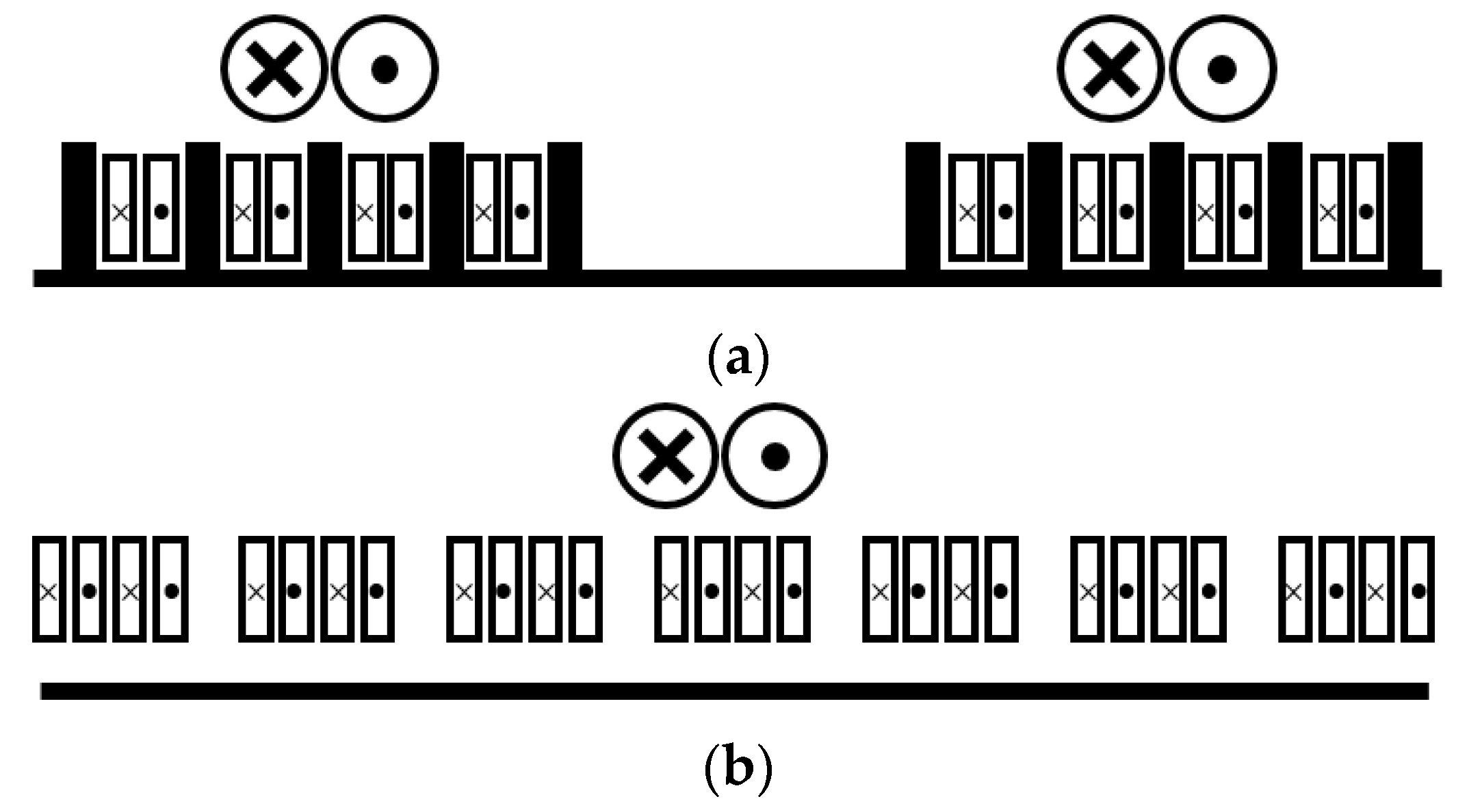
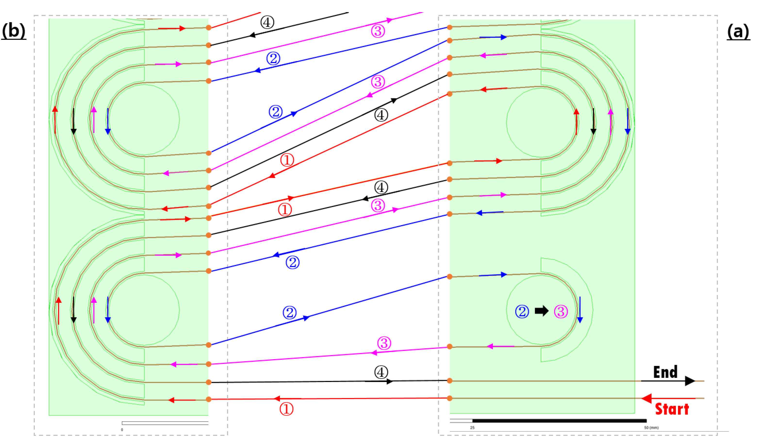
3. Winding Sequence of Bifilar-Meander Type

Figure 4 is an SFCL module design model applying the new winding method of the bifilar-meander type. Figure 4a–d proposes a new winding method design sequence. Figure 5 is a picture explaining the winding sequence of Figure 4a,b in detail. Figure 6 shows the winding sequence of Figure 4c,d. The winding sequence of the superconducting wire starts from the ‘Start’ position, and as seen in Figure 5, the superconducting wire is wound from ①. First, it is wound to the outermost point on the left column and then to the innermost point on the right column and goes up. Afterward, through Figure 6, it is possible to confirm the turning point where the ① winding is changed to the ② winding. The radius of the column, which is the turning point of the left and right sides, was designed to be about 10 mm, which means that the bending characteristics of the superconducting wire can be maintained as much as possible [20,21,22,23]. The winding of No. ② proceeds in the opposite direction to the winding of No. ①; it is wound to the outermost point on the right column and the innermost point on the left column and goes down. Figure 5 shows the position where ② winding is switched to ③ winding. The winding of No. ③ proceeds according to the flow charts in Figure 5 and Figure 6. Through Figure 6, it is possible to check the position of switching between winding ③ and winding ④. It can be confirmed that winding No. ④ reaches the ‘End’ position through Figure 5. Figure 5 and Figure 6 confirm the winding sequence of the superconducting wire. Through Figure 5 and Figure 6, it is possible to check the direction of each superconducting wire. It can be confirmed that the bifilar method is applied because the flow of the currents proceed in the opposite direction to each other.
Figure 7 confirms that about 18 layers can be designed based on the standard box (300 × 300 × 300) of the superconducting cold current module simulation model proposed in this paper. The total length of the superconducting wires used in 1 layer was about 25 m, and the total length of the superconducting wires used in 18 layers was about 450 m.

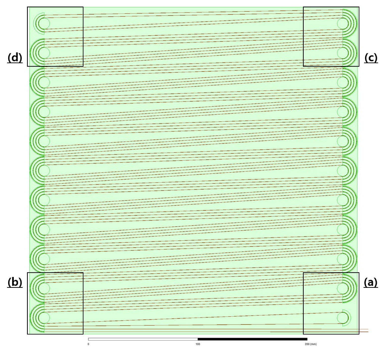
4. Maxwell Structural Comparative Analysis of Bifilar-Meander Type

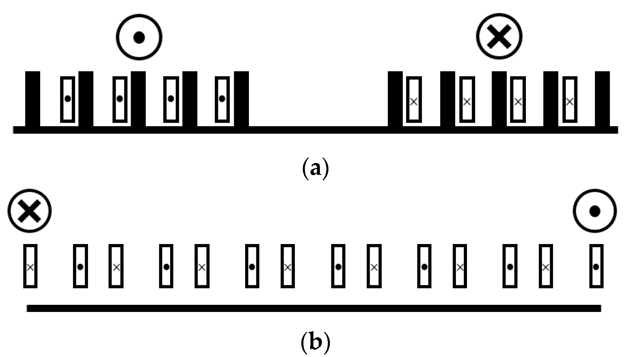
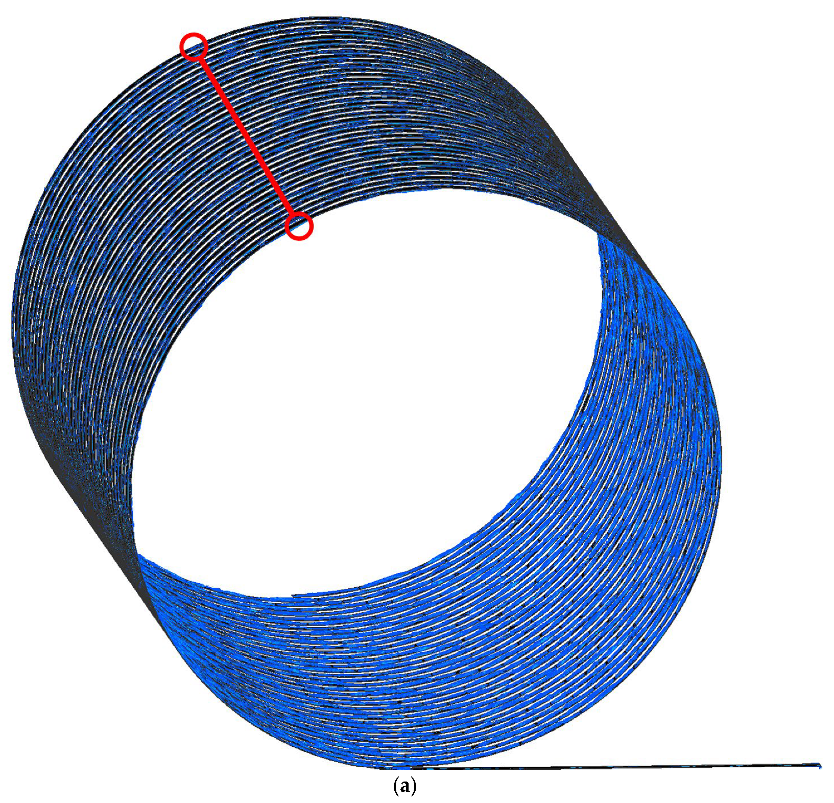
4.1. Winding Method of Superconducting Wire Rod

The superconducting cryogenic vessels are designed as double-walled structures using a vacuum layer that prevents heat ingress by conduction or convection. The cryogenic vessels containing the superconducting module are bulky for the above reasons. Therefore, if the volume of the cryogenic vessel is reduced with a spatially optimized design method, the amount of superconducting wire may be increased. In this paper, we intend to verify the spatial efficiency of the superconducting winding method through Maxwell’s modeling. The winding methods modeled through the Maxwell program are helical, spiral, and meander. This paper designed the bifilar method by applying the three-windings method.
The helical type, also called a solenoid coil, is a design method by winding a superconducting wire around a cylindrical tube. In this method, the volume of the bobbin is inevitably increased because the wire rod is wound around the cylinder’s axis. Figure 8 is a winding configuration diagram of a superconducting wire to which a helical type is applied.
Figure 8a shows the state in which one superconducting wire is designed. Figure 8b shows a form in which two superconducting wires are designed using the bifilar method, and the direction of the current flowing through each wire is opposite.
Figure 9 shows the spiral type, also called the pancake coil. Figure 9a is designed with one superconducting wire from the outside. In Figure 9b, the bifilar method is applied to the superconducting wire, and two wires with different current flows are designed side by side.
Figure 10 is a winding configuration diagram of a superconducting wire to which the meander method is applied. In Figure 10a, a superconducting wire is designed according to the winding method of the meander type proposed by us, and although it is designed as a single structure, two wires with different current flows are designed side by side. Figure 10b is a model of the improved meander method in which one more wire rod is added in Figure 10a, and it has the advantage of minimizing the impedance generated in the wire rod more.

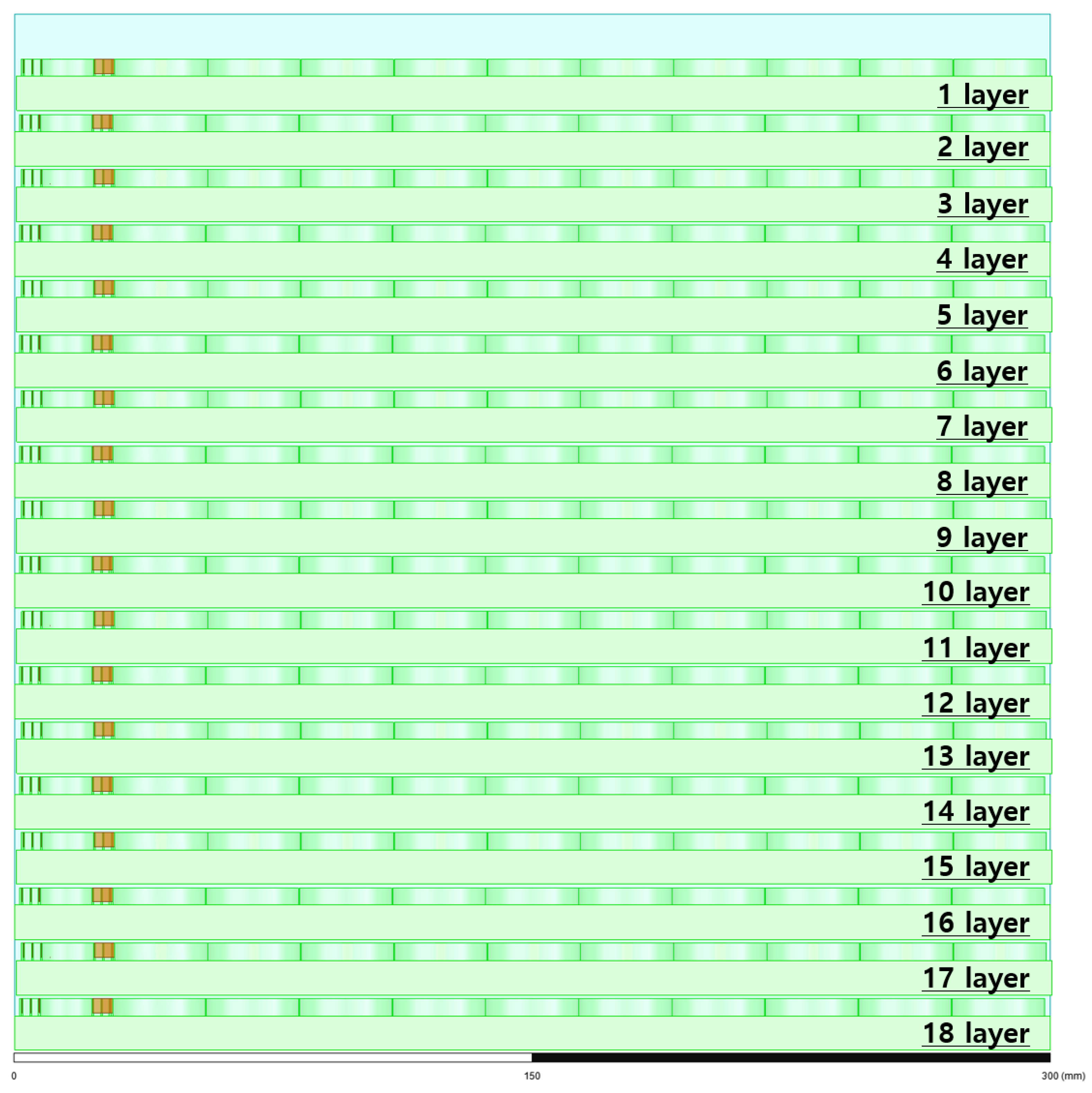
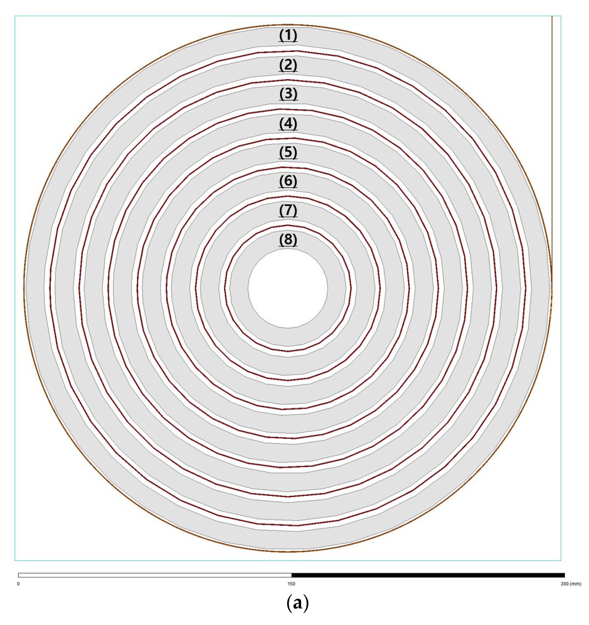
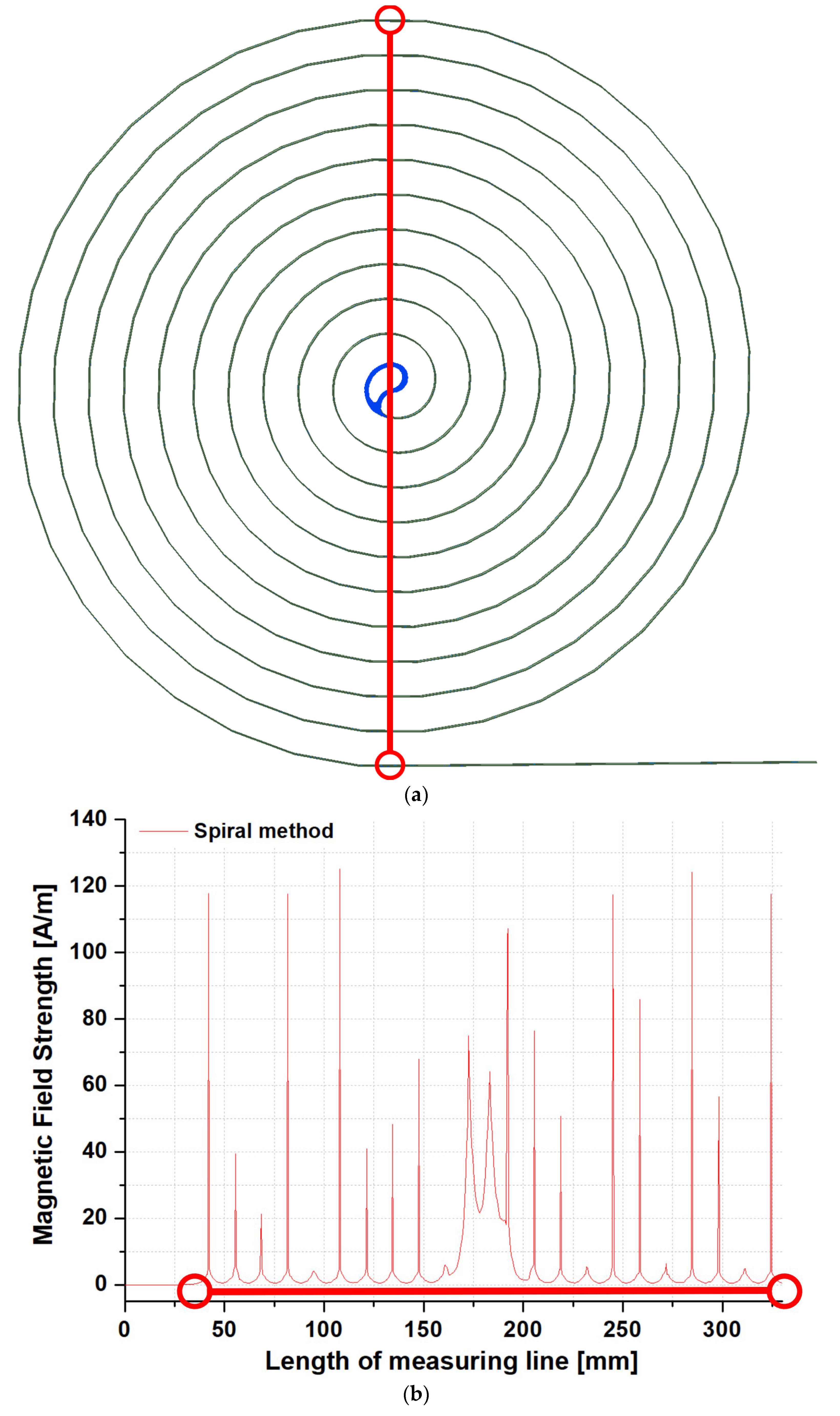
4.2. Design of the Simulation Model

To compare the helical, spiral, and meander types, the standard box to which the reference volume was applied was designed to be 300-300-300 (x-y-z). The superconducting wire used for this simulation modeling had a width of about 4.1 mm and a thickness of about 0.086 mm. The bobbin supporting the superconducting wire was designed based on about 10 mm, and the material was designed with Bakelite. The bending degree of the superconducting wire rod in the spiral and meander methods was designed to have a minimum diameter of about 10 mm [20,21]. We designed a model for each winding method through the Maxwell program and compared the amount of superconducting wire used according to the same volume (standard box). In addition, since the bifilar method was applied to the model of each winding type, the value of the impedance generated from the wire was also confirmed.
Figure 8 is a helical-type superconducting module according to the bifilar method applied. Figure 8a shows a helical-type superconducting module in the standard box. Figure 8b is a view from the top. The pitch value between superconducting wires is about 8 mm, and the total turns are 37. Figure 8c is a view from the side: the outer diameter of the bobbin is about 144 mm, and the inner diameter is about 134 mm. Figure 8d is an enlarged view of the wire rod of the superconducting module to which the bifilar method is applied. The distance between the superconducting wires (applied with the bifilar method) is designed to be about 0.1 mm, which is a distance considering the thickness of the Kapton tape (about 0.05 mm) surrounding each superconducting wire.
Figure 9 shows a spiral-type superconducting module to which the bifilar method is applied. Figure 9a shows a spiral-type superconducting module in the standard box. A bobbin is visible at the bottom of the superconducting wire, and the bobbin size is 300-300-10 (x-y-z). Figure 9b is a view from the top, designed in the shape of a pancake on the bobbin, and the distance between the superconducting wires was about 13 mm. Since the height of the bobbin in the helical type was about 10 mm, the height of the bobbin was designed to be about 10 mm in the spiral type. Therefore, the thickness of the superconducting wire and Kapton tape is included in the 3 mm free space, and the rest is the free space. The superconducting wire was wound a total of 10 times. Figure 9c is a side view, and the spiral-type model is located at the bottom of the standard box. The total height applied to the bobbin height and the superconducting wire’s height is about 14.1 mm. Figure 9d is an enlarged view of the wire rod of the superconducting module to which the bifilar method is applied. The distance between the superconducting wire and the superconducting wire is the same as the value of the helical bifilar method.
Figure 10 shows a meander-type superconducting module to which the bifilar method is applied. Figure 10a shows a meander-type superconducting module in the standard box. A bobbin is visible at the bottom of the superconducting wire. The bobbin is the same as the spiral model, and the size is 300-300-10 (x-y-z). Figure 10b is a view from the top, and it is designed with the winding method we proposed. When the superconducting wire is wound in the x-y axis direction, it is supported by the bobbin and wound. Therefore, it was necessary to set the support height to about 1 to 2 mm in the same way as the spiral model. The turning point where the superconducting wire is wound is located at 11 on each side, and it is designed with a minimum diameter of 10 mm. In addition, the passage through which the superconducting wire passes is about 0.5 mm, which is a free space considering the superconducting wire (0.086 mm) and Kapton tape. The superconducting wire is gone from the lower part to the upper part by winding both turning points alternately, and it is designed to be able to reciprocate twice. Figure 10c is a view from the side, and the meander-type model is located at the bottom of the standard box. The total height was applied with the bobbin height, and the superconducting wire’s height is about 14.1 mm, the same as the spiral model. Figure 10d is an enlarged picture of the wire rod of the superconducting module to which the bifilar method is applied. In this module, one superconducting wire goes through the entire section.

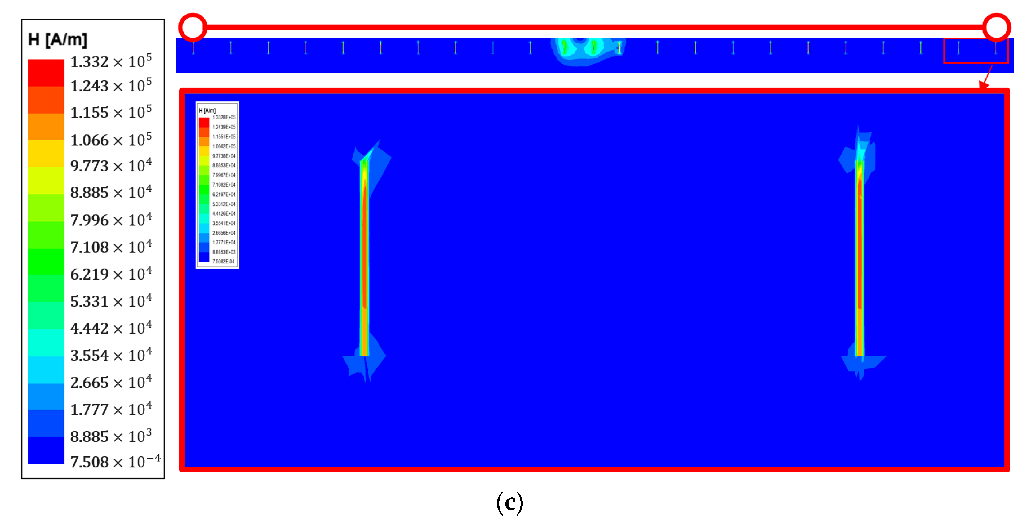
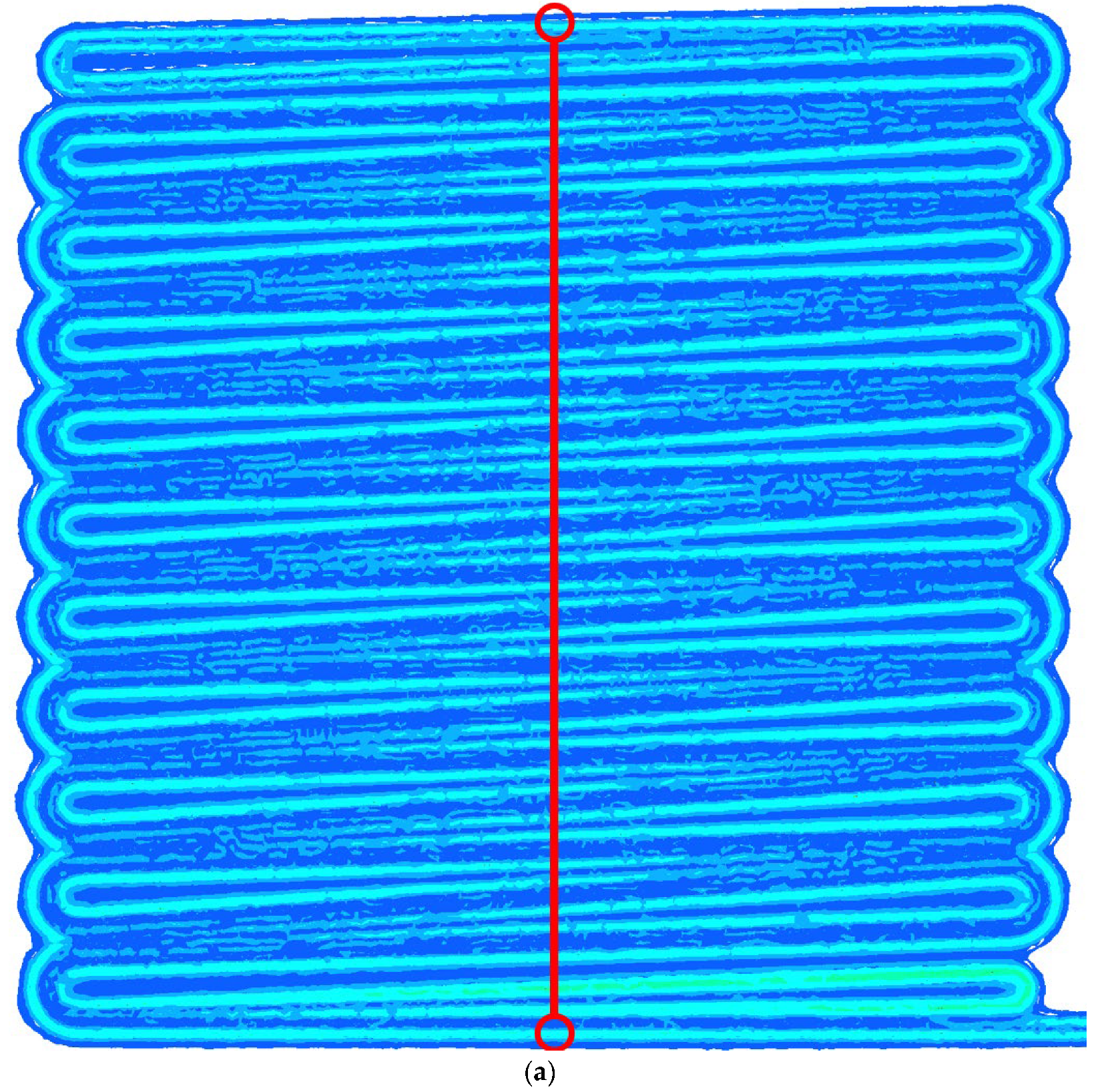
4.3. Results of the Simulation Model

The volume of each winding was compared through the Maxwell program. First, the total length of the superconducting wire used in one helical superconducting module was about 25.17 m. It was a module to which the diameter and circumference of the superconducting module and the bifilar method were applied. Second, the total length of the superconducting wire used in one bifilar-spiral superconducting module was about 0.89 m. In the bifilar-spiral type, the circle’s radius decreases as it goes inside the circle, so the amount of superconducting wire used is significantly reduced compared to the helical type. Third, the total length of the superconducting wire used in our proposed bifilar-meander superconducting module was about 25.17 m. This method used superconducting wire about 28 times more than the bifilar-spiral type and 2.6 times less than the bifilar-helical type.
Figure 11 is a picture implemented as a simulation model when all superconducting modules of each type are designed in the standard box. Figure 11a is a bifilar-helical superconducting module, and a total of seven extra superconducting modules were additionally designed inside the free space. However, it was not possible to apply modules of the same size, and it was designed by gradually reducing the diameter of the module. As a result of designing all superconducting modules, the total length of superconducting wires was about 153.55 m. Figure 11b is a bifilar-spiral superconducting module, and 17 modules were additionally designed from the existing modules. Unlike the bifilar-helical model, a model with the same conditions as the superconducting module for the existing bifilar-spiral type was added. The superconducting wire length used in the module was about 16.12 m. Figure 11c is a bifilar-meander superconducting module, and 17 modules were added to the existing modules. The superconducting wire length used in the module was about 453.04 m. The bifilar-helical type was the best for the amount of superconducting wire used in the one-layer module, but it was confirmed that the usable space was limited when it was designed as a multi-layer module. The advantage of the bifilar-meander-type winding method proposed in this paper is that it can significantly increase the amount of superconducting wire used when it is manufactured as a multi-layer module rather than a one-layer module.

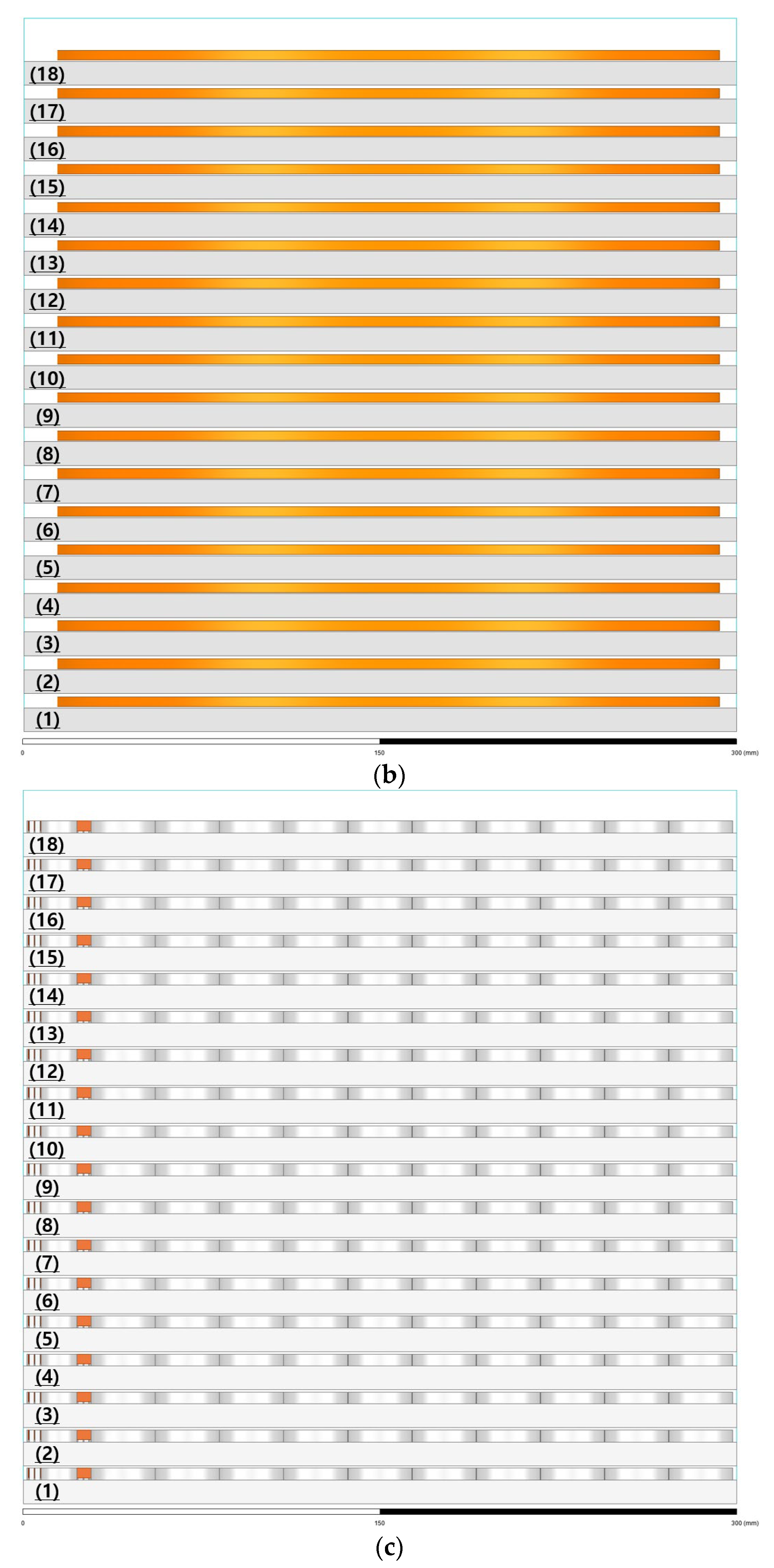
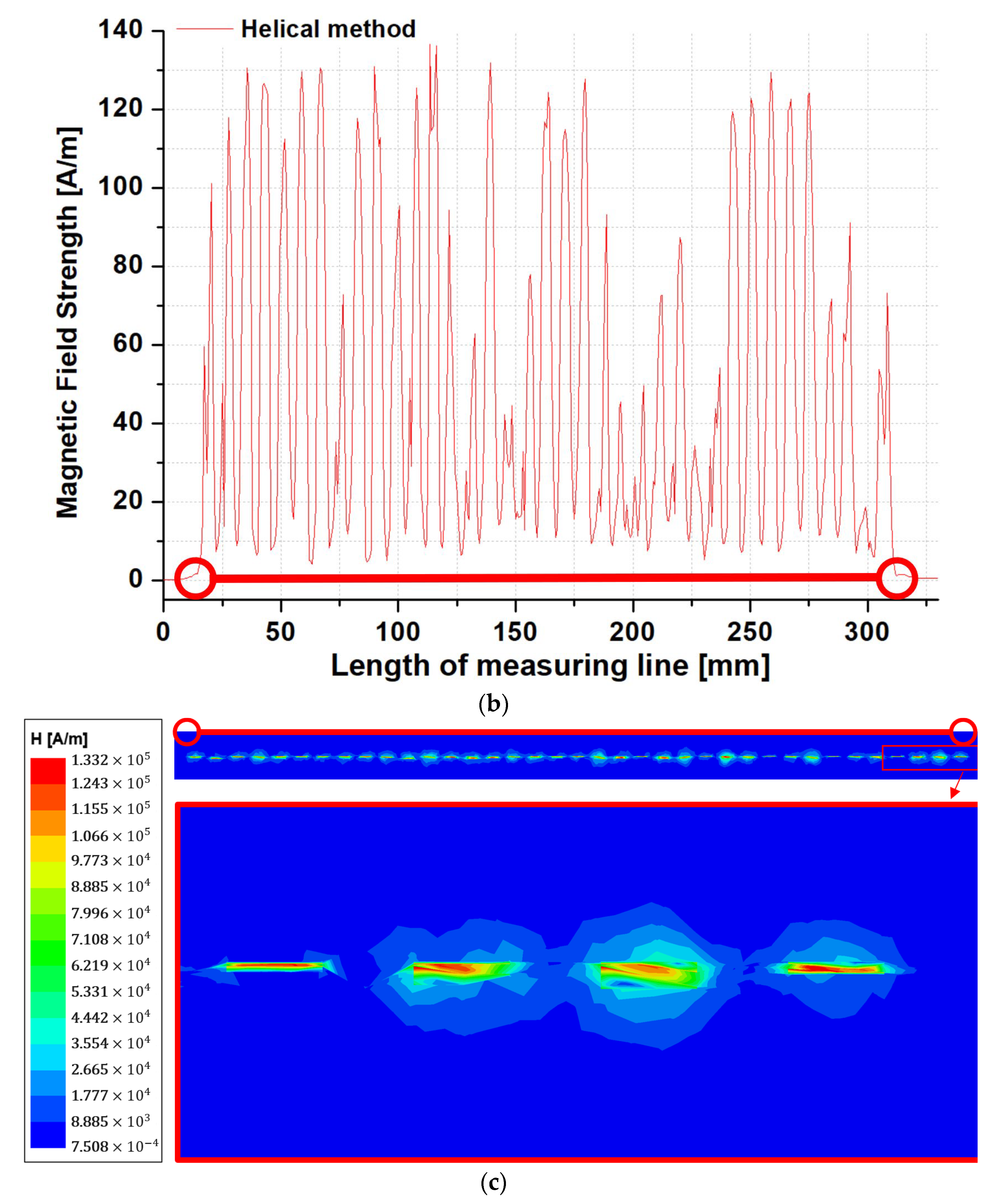
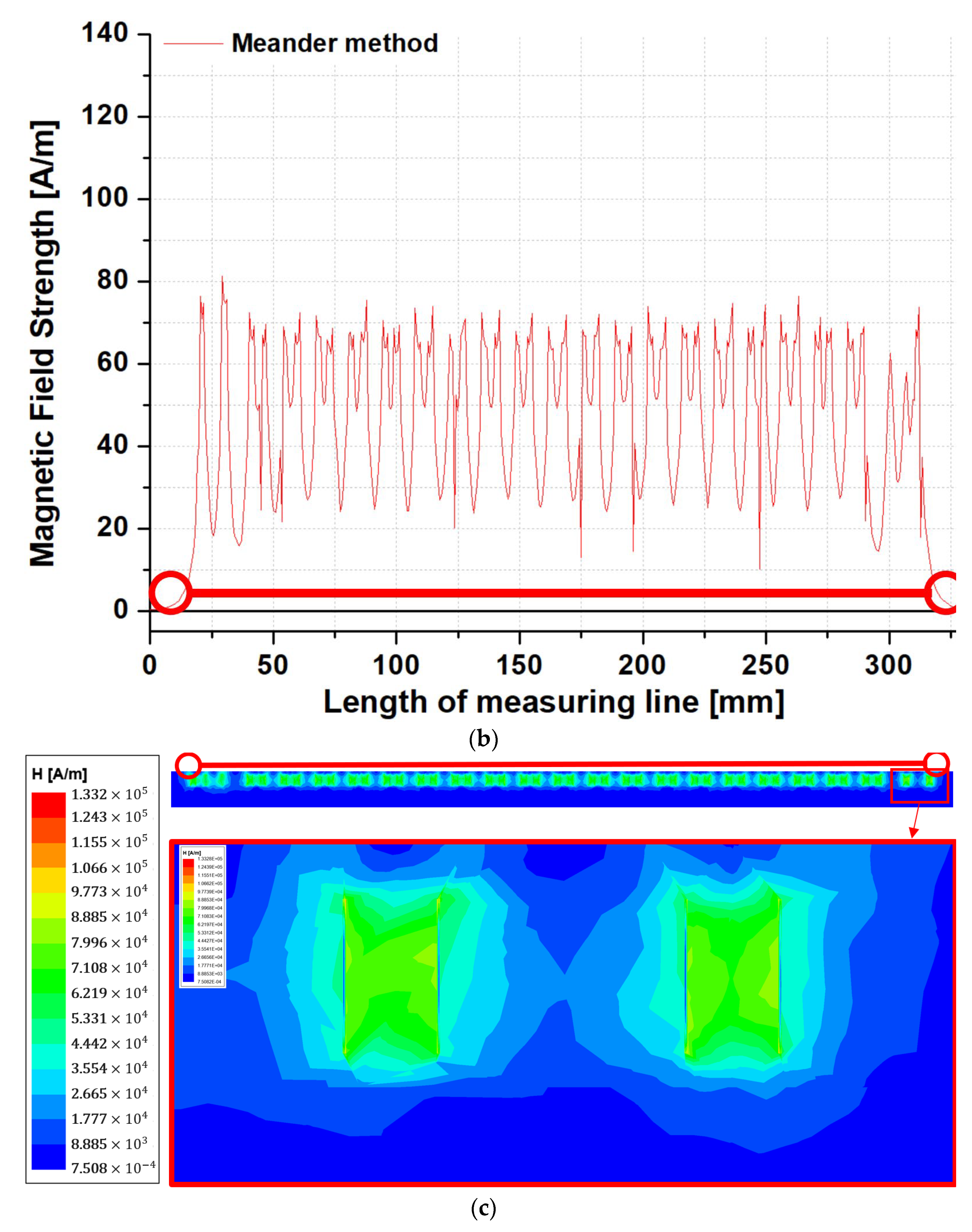
5. Maxwell Electromagnetic Comparative Analysis of Bifilar-Meander Type

Figure 12 shows the magnetic field distribution of the SFCL module using the bifilar-helical method. Figure 12a shows the magnetic field distribution of the bifilar-helical-type SFCL module, and a red line indicates the magnetic field measurement part of the superconducting wire. Figure 12b shows the graph of the strength of the magnetic field appearing on the red line in Figure 12a. Figure 12c shows the data confirmed through the distribution map of the magnetic field generated from some superconducting wires. As a result, the total length of the superconducting wire wound around the bifilar-helical-type SFCL module was 25.17 m. In addition, it was confirmed that the intensity of the magnetic field generated from each superconducting wire material occurred up to about 136.1 A/m, and the average was about 80.6 A/m. As the strength of the magnetic field increases, impedance is generated in the surrounding superconducting wire, adversely affecting it.
Figure 13 shows the magnetic field distribution of the SFCL module using the bifilar-spiral method. Figure 13a is the magnetic field distribution map of the bifilar-spiral-type SFCL module, and the magnetic field measurement part is also marked with a red line. Figure 13b shows the graph of the strength of the magnetic field appearing on the red line in Figure 13a. Figure 13c shows the distribution of magnetic fields generated from some superconducting wires. As a result, the total length of the superconducting wire wound around the bifilar-spiral-type SFCL module was about 0.89 m. In addition, it was confirmed that the intensity of the magnetic field generated from each superconducting wire material occurred up to about 125.6 A/m, and the average was about 64.4 A/m.
Figure 14 shows the magnetic field distribution of the SFCL module using the bifilar-meander method. Figure 14a is the magnetic field distribution map of the bifilar-meander-type SFCL module, and the magnetic field measurement part is also marked with a red line. Figure 14b shows a graph of the strength of the magnetic field appearing on the red line in Figure 14a. Figure 14c shows the distribution of magnetic fields generated from some superconducting wires. As a result, the total length of the superconducting wire wound around the bifilar-meander-type SFCL module was about 25.17 m. In addition, the intensity of the magnetic field generated in each superconducting wire was up to about 81.7 A/m, and the average was about 68.3 A/m.
Table 1 summarizes the usage per volume and the strength of the magnetic field for each superconducting wire winding.

6. Review

The simulation results are summarized as follows.
In this paper, the standard box was set as a standard to compare the design structures of three bifilar winding methods (helical, spiral, and meander methods). Moreover, through Figure 8, Figure 9 and Figure 10, one module was designed based on the standard box, and the result is shown in Figure 11. The maximum number of modules that can be manufactured based on the standard box was 8, 18, and 18 layers, respectively, in the order of helical, spiral, and meander. Since the helical type has a cylindrical structure, its extensibility was lower than the spiral type and meander type in terms of volume. Therefore, it was confirmed that the spiral and meander types are suitable for many layer structures.
Figure 12, Figure 13 and Figure 14 compare the total length of the superconducting wire used in one module and the magnetic field generated from the superconducting wire.
First, the figures show comparative data on the amount of superconducting wire used. The total lengths of the superconducting wires wound in the simulation module produced in Figure 8 and Figure 10 were approximately 25.17, 0.89, and 25.17 m, respectively, in the order of helical, spiral, and meander. Since the spiral type is manufactured by winding in the form of a pancake, the amount of superconducting wire used is reduced by about 28 times compared to the helical and meander types. Therefore, it was confirmed that the helical and meander types are structures that can use many superconducting wires.
Second, the figures show magnetic field comparison data generated from superconducting wires.
The maximum magnetic field strength values for each type identified in Figure 12, Figure 13 and Figure 14 were about 136.1, 125.6, and 81.7 A/m in the order of helical, spiral, and meander. Furthermore, each type’s average magnetic field strength value was about 80.6, 64.4, and 68.3 A/m. In the helical type, both the maximum and average values of the magnetic field strength were higher than the other types. In the spiral type, the magnetic field intensity was about 43.9 A/m higher than the meander type at the maximum value. In the meander type, the magnetic field intensity was the lowest at the maximum value, about 81.7 A/m, compared to other types.

7. Conclusions

Superconducting DC cutoff technology, which combines the SFCL and a mechanical DC circuit breaker, is a method to solve fault currents based on DC characteristics. The fault current that occurs in the transient state of the DC system is very dangerous because of its fast growth rate and that it has no cutoff zero point. Nonetheless, supply and demand for DC have soared, increasing the breaking capacity of DC systems. We studied a winding method of the SFCL that quickly current-limits the initial fault current according to the increasing DC breaking capacity. In the existing winding method, a helical type and a spiral type were widely used. However, in order to current-limit the DC fault current that increases with this winding method, the number of superconducting wires used must be increased. As a result, the volume of equipment of the SFCL increases, making commercialization difficult. In this paper, we proposed a bifilar-meander-type winding method for superconducting winding. By applying the bifilar method, inductance can be reduced and the effect of increasing or decreasing the volume can be reduced under the condition of increasing the number of superconducting wires used. Therefore, using the Maxwell program, the bifilar-meander-type winding method was divided into structural and electromagnetic parts for comparative analysis. First, the existing bifilar-helical type, bifilar-spiral type, and bifilar-meander type were modeled and compared based on the standard box. Second, the inductance generated between superconducting wires under the same conditions was compared and analyzed for each model of each winding method.
The results can be summarized as follows:
1.
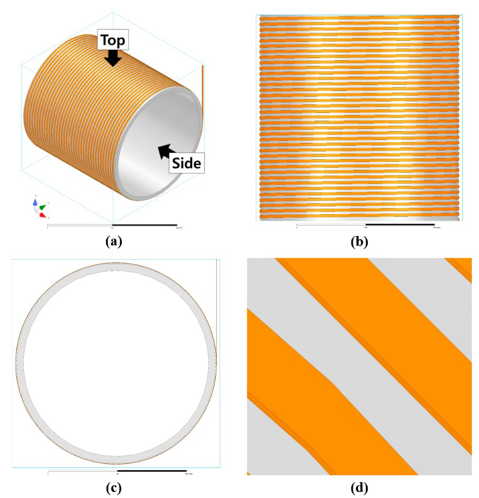
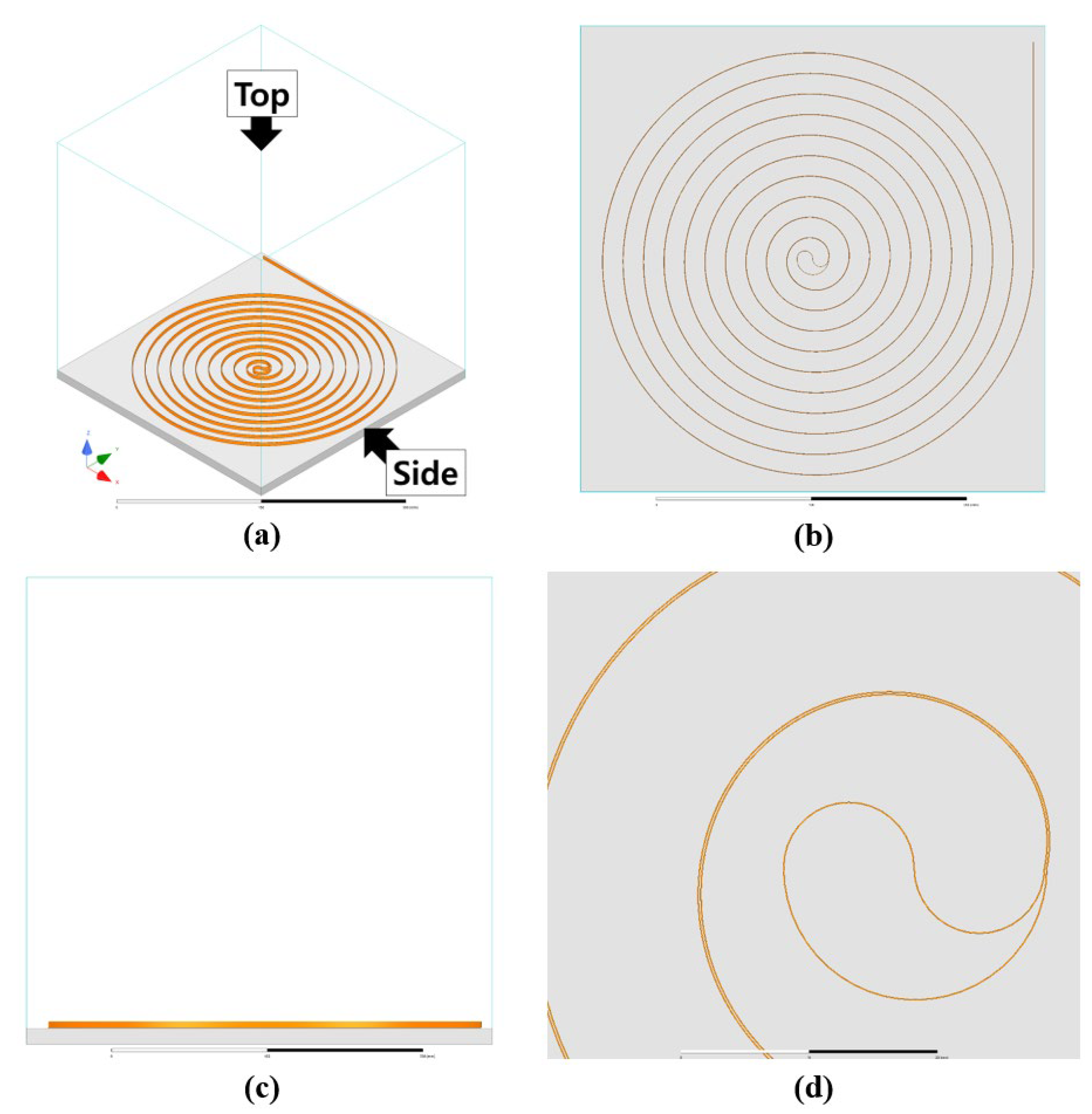
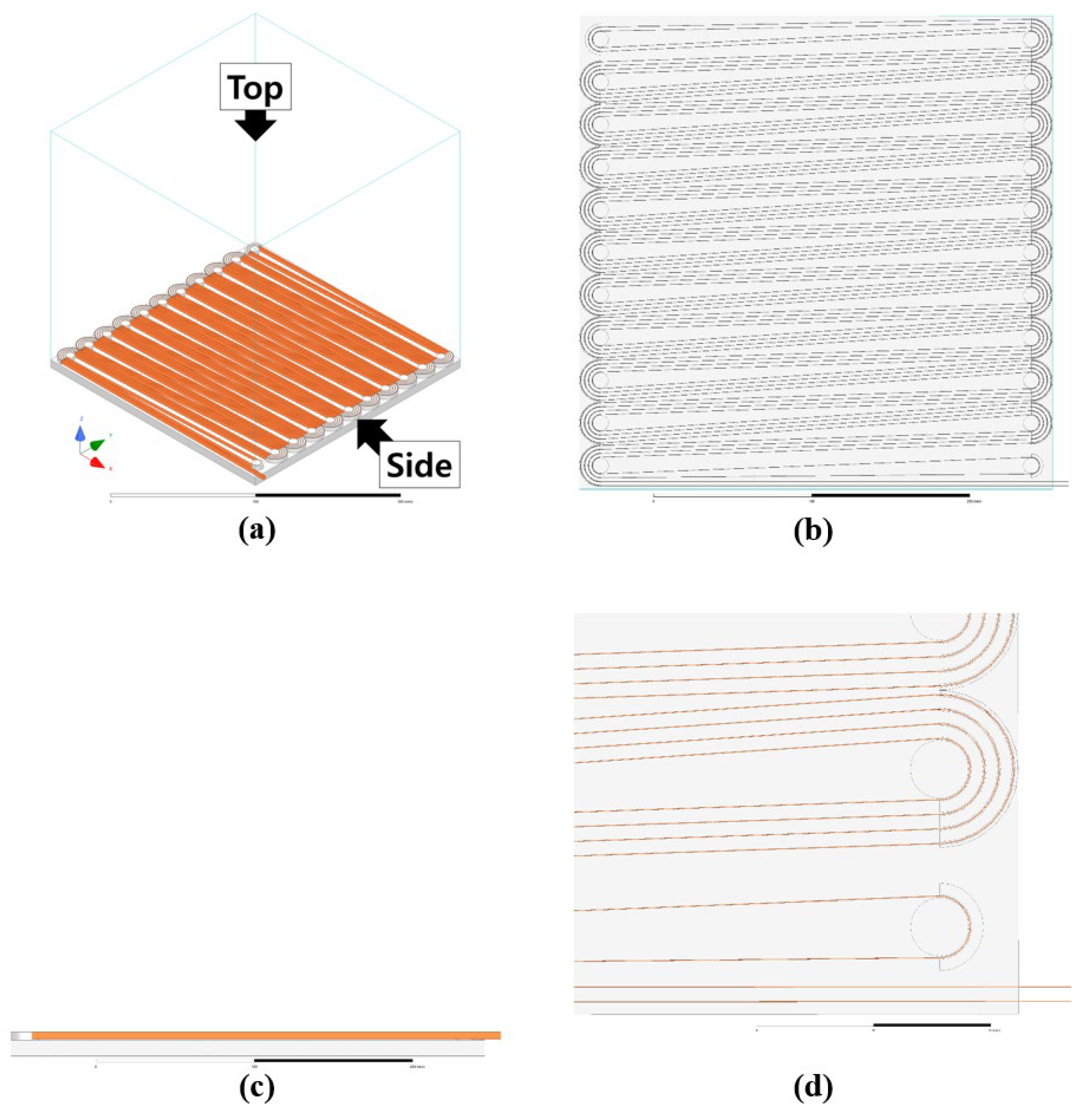
The winding methods suitable for the modular structure of the SFCL are the spiral type and meander type.
2.
Helical and meander types are optimal for increasing the superconducting wire used in the SFCL.
3.
Based on the simulation results, the magnetic field intensity generated from the superconducting wires of the SFCL was the lowest in the meander type. It occurred evenly from all superconducting wires.
The bifilar-meander winding method proposed in this paper is a new idea that can increase the number of superconducting wires and generate a lower magnetic field strength than the existing winding method. Based on this idea, we plan to conduct experimental research that can prove the simulation result data by producing a prototype.

Author Contributions

Conceptualization, S.-Y.P.; Methodology, S.-Y.P. and J.-S.J.; Software, S.-Y.P. and G.-W.K.; Validation, H.-S.C.; Formal analysis, S.-Y.P. and J.-S.J.; Investigation, S.-Y.P.; Resources, S.-Y.P.; Data curation, S.-Y.P. and G.-W.K.; Writing – original draft, S.-Y.P.; Writing – review & editing, S.-Y.P. and H.-S.C.; Visualization, S.-Y.P.; Supervision, H.-S.C.; Project administration, H.-S.C.; Funding acquisition, H.-S.C. All authors have read and agreed to the published version of the manuscript.

Funding

This study was supported by research fund from Chosun University, 2022.

Data Availability Statement

Not applicable.

Conflicts of Interest

The authors declare no conflict of interest.

References

  1. KEITI (Korea Environmental Industry and Technology Institute). Emissions Reduction through the Upgrade of Coal-Fired Power Plants; KONETIC Overseas Investigation Report; KEITI: Seoul, Republic of Korea, 2015; Volume 104. [Google Scholar]
  2. ABB. ABB Review—60 Years of HVDC; ABB: Zürich, Switzerland, 2014. [Google Scholar]
  3. Hitachi ABB Power Grids. NordLink HVDC Interconnector-Changing European Power Landscape; Hitachi ABB Power Grids: Zürich, Switzerland, 2021. [Google Scholar]
  4. Callavik, M.; Lundberg, P.; Hansson, O. NORDLINK pioneering VSC-HVDC interconnect or between Norway and Germany. In ABB White Paper; ABB: Zürich, Switzerland, 2015; pp. 1–6. [Google Scholar]
  5. Pei, X.; Cwikowski, O.; Vilchis-Rodriguez, D.S.; Barnes, M.; Smith, A.C.; Shuttleworth, R. A review of technologies for MVDC circuit breakers. In Proceedings of the IECON 2016—42nd Annual Conference of the IEEE Industrial Electronics Society, Florence, Italy, 23–26 October 2016; pp. 3799–3805. [Google Scholar] [CrossRef]
  6. Xiang, B.; Liu, Z.; Geng, Y.; Yanabu, S. DC circuit breaker using superconductor for current limiting. IEEE Trans. Appl. Supercond. 2015, 25, 5600207. [Google Scholar]
  7. Callavik, M.; Blomberg, A. The hybrid HVDC breaker. In ABB Grid Systems; ABB: Zürich, Switzerland, 2012. [Google Scholar]
  8. Park, S.-Y.; Choi, H.-S. Operation Characteristics of Mechanical DC Circuit Breaker Combined with LC Divergence Oscillation Circuit for High Reliability of LVDC System. Energies 2021, 14, 5097. [Google Scholar] [CrossRef]
  9. Park, S.Y.; Kim, G.W.; Jeong, J.S.; Choi, H.S. The modeling of the LC divergence oscillation circuit of a superconducting DC circuit breaker using PSCAD/EMTDC. Energies 2022, 15, 780. [Google Scholar] [CrossRef]
  10. Park, S.Y. A study on the characteristics of superconducting DC circuit breakers for securing DC power grid supply reliability. Ph.D. Dissertation, Chosun University Graduate School, Gwangju, Republic of Korea, 2022. [Google Scholar]
  11. Kim, G.; Lee, J.; Park, J.; Choi, H.; Lee, M. A Zero Crossing Hybrid Bidirectional DC Circuit Breaker for HVDC Transmission Systems. Energies 2021, 14, 1349. [Google Scholar] [CrossRef]
  12. Noe, M.; Juengst, K.-P.; Werfel, F.; Cowey, L.; Wolf, A.; Elschner, S. Investigation of high-Tc bulk material for its use in resistive superconducting fault current limiters. IEEE Trans. Appl. Supercond. 2001, 11, 1960–1963. [Google Scholar] [CrossRef]
  13. Majoros, M.; Ye, L.; Campbell, A.M.; Coombs, T.A.; Sumption, M.D.; Collings, E.W. Modeling of Transport AC Losses in Superconducting Arrays Carrying Anti-Parallel Currents. IEEE Trans. Appl. Supercond. 2007, 17, 1803–1806. [Google Scholar] [CrossRef]
  14. Zhang, J.; Dai, S.; Ma, T.; Xu, Y.; Yan, X. High-Frequency Impulse Modeling and Longitudinal Insulation Analysis of Bifilar Superconducting Coil. IEEE Trans. Appl. Supercond. 2020, 31, 1–8. [Google Scholar] [CrossRef]
  15. Akbar, A.; Dutoit, B. Fast Quench Detection in SFCL Pancake Using Optical Fibre Sensing and Machine Learning. IEEE Trans. Appl. Supercond. 2022, 32, 1–5. [Google Scholar] [CrossRef]
  16. Kang, H.G.; Lee, C.J.; Nam, K.W.; Yoon, Y.S.; Chang, H.M.; Ko, T.K.; Seok, B.Y. Development of a 13.2 kV/630 A (8.3 MVA) high temperature superconducting fault current limiter. IEEE Trans. Appl. Supercond. 2008, 18, 628–631. [Google Scholar] [CrossRef]
  17. Jo, H.C.; Chang, K.S.; Kim, Y.J.; Chu, S.Y.; Kim, H.J.; Kim, H.M.; Yoon, Y.S.; Ko, T.K. Operating Characteristics of Oval-Shaped Resistive Superconducting Fault Current Limiter. IEEE Trans. Appl. Supercond. 2011, 21, 1246–1249. [Google Scholar] [CrossRef]
  18. Ahn, M.C.; Jang, J.Y.; Ko, T.K.; Lee, H. Novel Design of the Structure of a Non-Inductive Superconducting Coil. IEEE Trans. Appl. Supercond. 2010, 21, 1250–1253. [Google Scholar] [CrossRef]
  19. Shen, B.; Chen, Y.; Li, C.; Wang, S.; Chen, X. Superconducting fault current limiter (SFCL): Experiment and the simulation from finite-element method (FEM) to power/energy system software. Energy 2021, 234, 121251. [Google Scholar] [CrossRef]
  20. Kb, A.; Thomas, R.J.; Mathai, J.P.; Nijhuis, A. Analytical and Numerical Investigations on the Degradation of REBCO Based Superconducting Tapes Under Bending. IEEE Trans. Appl. Supercond. 2021, 31, 8400712. [Google Scholar] [CrossRef]
  21. Pekarčíková, M.; Michalcová, E.; Frolek, L.; Šouc, J.; Gogola, P.; Drienovský, M.; Skarba, M.; Mišík, J.; Gömöry, F. Effect of mechanical loading on coated conductor tapes due to winding onto round cables. IEEE Trans. Appl. Supercond. 2018, 28, 8400505. [Google Scholar] [CrossRef]
  22. Takayasu, M. Width-bending characteristic of REBCO HTS tape and flat-tape Rutherford-type cabling. Supercond. Sci. Technol. 2021, 34, 125020. [Google Scholar] [CrossRef]
  23. Song, W.; Pei, X.; Zeng, X.; Yazdani-Asrami, M.; Fang, X.; Fang, J.; Jiang, Z. AC Losses in Noninductive SFCL Solenoidal Coils Wound by Parallel Conductors. IEEE Trans. Appl. Supercond. 2020, 30, 5602509. [Google Scholar] [CrossRef]
Figure 1. Cross sections of the helical-type winding method. (a) Original model; (b) Bifilar method.
Energies 16 01866 g001
Figure 2. Cross sections of the spiral-type winding method. (a) Original model; (b) Bifilar method.
Energies 16 01866 g002
Figure 3. Cross section of the meander-type winding method. (a) Original model; (b) Bifilar method.
Energies 16 01866 g003
Figure 4. Simulation design model of the bifilar-meander type: (a) bottom right part, (b) bottom left part, (c) top right part, (d) top left part.
Energies 16 01866 g004
Figure 5. Winding flow diagram of (a) and (b) (bottom).
Energies 16 01866 g005
Figure 6. Winding flow diagram of (c) and (d) (top).
Energies 16 01866 g006
Figure 7. Bifilar-meander-type superconducting current module designed in a standard box.
Energies 16 01866 g007
Figure 8. Superconducting module modeling with the bifilar-helical type: (a) overall, (b) top view, (c) side view, (d) bifilar view.
Energies 16 01866 g008
Figure 9. Superconducting module modeling with the bifilar-spiral type: (a) overall, (b) top view, (c) side view, (d) bifilar view.
Energies 16 01866 g009
Figure 10. Superconducting module modeling with the bifilar-meander type: (a) overall, (b) top view, (c) side view, (d) bifilar view.
Energies 16 01866 g010
Figure 11. A complete superconducting module that consists of the same module of each type with the free space of each winding method in the standard box: (a) helical type, (b) spiral type, (c) meander type.
Energies 16 01866 g011aEnergies 16 01866 g011b
Figure 12. Magnetic field distribution diagram of bifilar-helical type: (a) the magnetic field distribution, (b) the strength of the magnetic field, (c) the distribution map of the magnetic field generated from some superconducting wires.
Energies 16 01866 g012aEnergies 16 01866 g012b
Figure 13. Magnetic field distribution diagram of bifilar-spiral type: (a) the magnetic field distribution, (b) the strength of the magnetic field, (c) the distribution map of the magnetic field generated from some superconducting wires.
Energies 16 01866 g013aEnergies 16 01866 g013b
Figure 14. Magnetic field distribution diagram of bifilar-meander type: (a) the magnetic field distribution, (b) the strength of the magnetic field, (c) the distribution map of the magnetic field generated from some superconducting wires.
Energies 16 01866 g014aEnergies 16 01866 g014b
Table 1. Superconducting wire usage and force of the magnetic field strength according to each winding method.
Winding TypeBifilar-Helical TypeBifilar-Spiral TypeBifilar-Meander Type
SingleModule1 layer1 layer1 layer
Available windingsabout 25.17 mabout 0.89 mabout 25.17 m
The magnetic field strength of a superconducting wire(Max.) about 136.1 A/m
(Av.) about 80.6 A/m
(Max.) about 125.6 A/m
(Av.) about 64.4 A/m
(Max.) about 81.7 A/m
(Av.) about 68.3 A/m
MultiAvailable modules8 layers18 layers18 layers
Available windingsabout 153.55 mabout 16.02 mabout 453.06 m
Disclaimer/Publisher’s Note: The statements, opinions and data contained in all publications are solely those of the individual author(s) and contributor(s) and not of MDPI and/or the editor(s). MDPI and/or the editor(s) disclaim responsibility for any injury to people or property resulting from any ideas, methods, instructions or products referred to in the content.

