Abstract
The delivery of electricity employing an electromagnetic field that extends across an intervening region is called a wireless power transfer (WPT). This approach paves the way for electric vehicles (EVs) to use newly available options to reduce their environmental impact. This article is a review that examines the WPT technology for use in electric vehicle applications from both the technical aspect and the environmental impact. This review will attempt to accomplish the following objectives: (1) describe the present state of the technology behind the development and application of a WPT across the transportation industry; (2) substantiate the actual implementation of WPT EV systems; and (3) estimate the functioning of the autonomous system, as well as detect the potential stumbling blocks and openings for enhancement. The most recent advancements and implementation in compensating topologies, power electronics converters, and control techniques are dissected and debated scientifically to improve the system’s performance. To evaluate the performance from a sustainable perspective, energy, environmental, and economic factors are utilized, and at the same time, policy drivers and health and safety problems are researched.
1. Introduction
Nicola Tesla performed efforts to transfer power a century ago wirelessly [1,2]. WPT has been the subject of extensive study in recent decades to speed up the widespread adoption of electric devices. Examples include EVs, cell phones, implanted medical devices, robots, and household electronics. In most cases, an electromagnetic field is used to transmit energy. The WPT is becoming increasingly popular for several reasons, the most important of which is the inherent simplicity of the technology and the possibility of a continuous operation with no interruptions for recharging.
However, magnetic coupling WPT, whether inductive-based or resonant-based, is the method of choice for near-field transmission since it causes significantly less damage to the surrounding environment. In addition, power transmission for any long distance between the Earth and solar power satellites can be accomplished using a wireless power transfer that uses electromagnetic radiation. This radiation can take the form of microwaves or lasers. This study focuses on the magnetically coupled WPT for any electric vehicle charging application and has made the subject of a significant amount of research [3,4,5,6,7,8]. In terms of its operational modes, a WPT can be of two categories: (1) static WPT, which involves charging the battery while the vehicle is parked, and (2) dynamic WPT, which involves the battery being charged while the vehicle is moving down a roadway that is enabled for WPT. The WPT for electric vehicles has the potential to remove some of the barriers that prevent vehicle electrification and achieve sustainable mobility [9]. This would mean that wired chargers would no longer be necessary. A WPT can significantly reduce the size of the onboard battery in an electric vehicle, meaning it offers much more convenience. In the case of electric transit buses with a stationary WPT, for instance, the onboard [10,11] charging station can be reduced by approximately two-thirds of the size due to the many situation charges made while waiting for and unloading the passengers at bus stops. It is acceptable to bear a significantly small onboard battery because these charges en route still meet the vehicle route requirements. There is a considerable reduction in the vehicle weight because the weight of the battery pack can be as much as one-fourth of the total weight of an electric bus which is built for continuous operation during the daytime [12]. Reducing the size of the battery has substantial ramifications in terms of lowering the overall weight of the vehicle and raising the economical operation of the car [10]. Theoretically, in the case of passenger cars on significant highways based on a dynamic WPT, widespread charging stations could make it possible for EVs to have an unlimited range with a small battery capacity [13,14].
Nonetheless, the WPT for EVs raises new questions and trade-offs about the environment, which have sparked debate in academic and business communities. The benefits of a reduced battery size and enhanced fuel economy must be weighed against the costs of deploying widespread WPT infrastructure. A lowered charging efficiency at high speeds is a significant cause for concern, as is the question of whether or not a dynamic WPT is technically and financially feasible. Various parts of static and dynamic charging are illustrated in Figure 1.
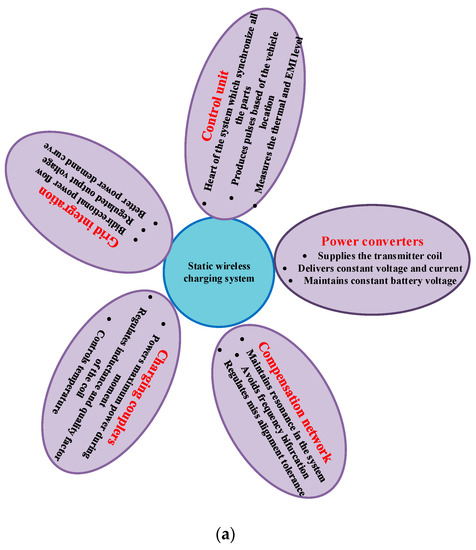
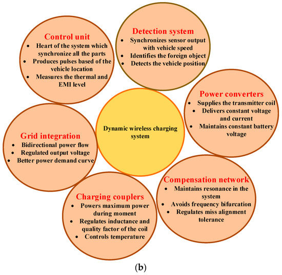
Figure 1.
Wireless charging: (a) static and (b) dynamic.
The course of the paper is organized as follows: Section 2 deals with compensation topologies, and the power converter topologies and control structures are briefed in Section 3 and Section 4, respectively. In Section 5, the frequency and power level determination are explained. The environmental and energy assessment and policy and economic forecasting are detailed in Section 6 and Section 7, respectively. In Section 8, the safety and health of using EVs are explained. The recent trends in the EV WPT and the paper’s conclusion are explained in Section 9 and Section 10, respectively.
2. Compensation Topologies
To generate RIPT in the static inductive charging systems for electric vehicles, compensating capacitors are introduced in parallel and series combinations, as shown in Figure 2. This is done on both the receiver and transmitter sides of the system. In Figure 3, there are four distinct topologies for compensation networks. These topologies are stated as series–series (SS), parallel–parallel (PP), parallel–series (PS) and series–parallel (SP). It is necessary to have the source compensated to eliminate the phase difference between the current and the voltage and to cut down on the amount of reactive power produced by the source [15,16].
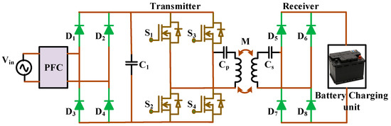
Figure 2.
Resonant power inductive transfer topology.
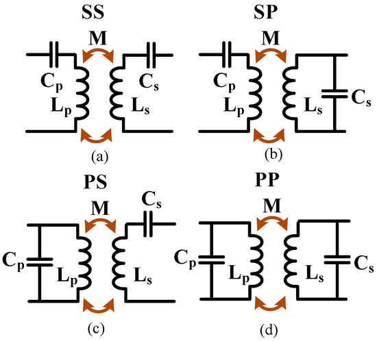
Figure 3.
Compensation networks (a) SS; (b) SP; (c) PS; (d) PP.
The system load transfer capacity and efficiency can be maximized to their full potential by implementing a secondary compensating network [17]. In addition, the particular application requirements contained in the WPT are taken into consideration when choosing the network topologies to implement. The PS- and PP-compensated wireless charging station (WCS) has safeguards to ensure that the source coil will not function if the receiver coil is not there. Even though it provides a risk-free setting, the system cannot transfer adequate power when the transmitter and receiver are not appropriately positioned [18].
Additionally, extra series inductors are needed to manage the source current to flow parallel within the resonating circuit. A capacitor’s rating depends on the magnetic resonance and its Q factor [19]. This is how the capacitor achieves its value. In an SP-based compensated WCS, the primary compensating capacitor’s value is independent of the mutual inductance. As a result, this system can provide more power-transferring capacity when compared to the graded system.
Nevertheless, it is pretty sensitive to changes in the load [20]. Because it has two significant benefits also considering cybersecurity [21,22], the SS-compensating topology is the one that is best suited for EV applications. The first benefit is that the enhanced current and mutual inductance do not affect the values of the capacitor on either of the sides. As a result, the mutual coupling and loads do not affect the sources’ or receivers’ resonance frequencies; instead, they depend on the secondary and main coils’ self-inductance [16]. Such systems can retain a unity power factor by drawing active power at the resonance frequencies because the reflecting resistance from the reception does not contribute an imaginary component in the transmitter coil [20]. This is the second advantage of such systems. The suggested SS topology based on the WCS may provide a more reliable method for charging batteries since it may supply the cell with a consistent voltage and current [18]. Table 1 [17,18,23,24] outlines the supplementary benefits and characteristics of various compensation networks, all of which are utilized in the WPT for electric vehicles (EVs).

Table 1.
Advantages and features of the compensation network.
3. Power Converter Topologies
Figure 4 shows that a typical grid-to-vehicle static and dynamic wireless power transfer (DWPT) system needs power electronic converters that work in four stages. On the primary side, these are front-end converters and HF inverters; on the secondary side, there are rectifiers and the back-end DC-DC converters are connected. Table 2 shows the transfer stages, the topologies used at each stage, and the control handles they offer.
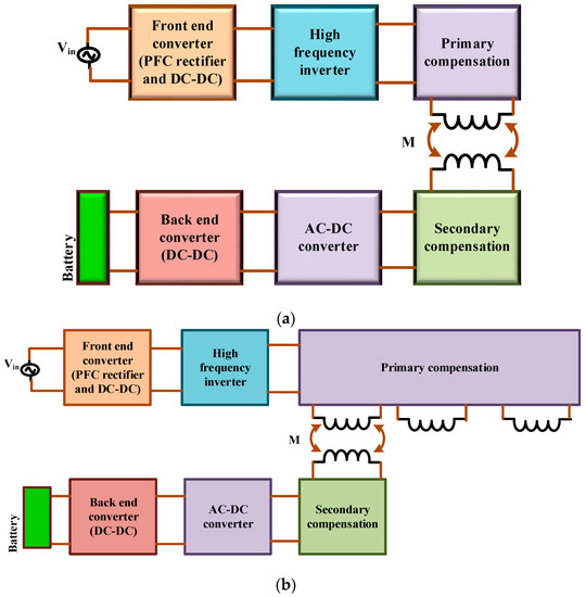
Figure 4.
Block diagram of typical grid-to-vehicle WPT: (a) static WPT and (b) dynamic WPT.
Table 2.
At various stages of the converter.
3.1. Source Side Converter
Front-end primary converters typically consist of rectifiers on the grid side, a power factor correction (PFC) converter, and a DC-DC converter on the other stages. Front-end primary converters are also known as buck converters. The buck converter is the most common form of the several types of DC-DC converters, which can also take the form of boost or buck-boost converters. The controls from DC-DC converters at the front-end assist in running the WPT stages at a specific operating point, which aids in their soft switching [25,26,27,28,29].
The WPTs primary inverter configurations consist of being voltage-fed from a single-phase, three-phase, or multistage inverter [27,30,31], current-fed push–pull [25], and class EF structures [32]. These inverters are depicted in Figure 5 and convert voltages from one phase. The inverters suggested in DWPT systems may drive a single or several coils that offer various control options for activating and deactivating the appropriate charger. They can come with varying degrees of complexity of the actual implementation.
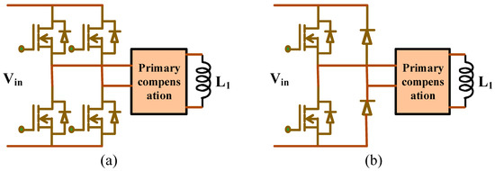
Figure 5.
Static WPT high-frequency converter topologies: (a) full bridge type and (b) half bridge type.
3.2. Static WPT Source Side Converter
The static type WPT systems are commonly energized using a high frequency inverter at the preprimary side using full bridge topology. The other alternative method is to reduce the number of switches the half bridge inverters are proposed. In both methods, the inverters are designed to operate at the high frequency operation using square PWM techniques. Figure 5 shows the two types of static WPT primary side inverter topologies. In order to minimize the harmonics distortion in both the techniques, the compensator capacitors are designed at the primary and secondary side of the coil.
3.3. Dynamic WPT Source Side Converter
Generally, the DWPT systems are designed to operate using a high-power, high-frequency inverter. Figure 6 shows the various topologies adapted in the DWPT primary side inverter. For the cost-effective solutions, single high-power inverters are designed to power multiple coils connected in series with the primary compensators. However, these methods are able to power only one EV running in the lane at a time. Multiple inverters connected at discrete locations can switch ON and OFF the individual modules based on the vehicle’s position. It is also suitable for the simultaneous power transfer to multiple vehicles in the same dynamic charging lane. Moreover, a fault in any inverter will not hamper the entire charging lane. However, the investment cost on the multiple inverter modules is higher compared with the single inverter DWPT system.
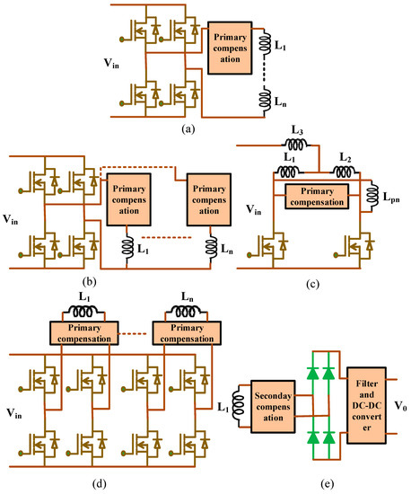
Figure 6.
Various high-frequency converter topologies for DWPT feeding; (a) multiple coils connected in series; (b) multiple coils connected in parallel; (c) push–pull converter; (d) multi-phase converter; (e) secondary compensation topologies.
3.4. Load-Side Converter
Diode rectifiers are the most common solution for secondary-side converters, and many researchers have worked to make the secondary side as straightforward and uncomplicated as possible [39]. The use of a synchronous rectification mode is restricted since it simply enhances the efficiency [40,41] without offering any additional advantages in terms of the control. Most secondary-side-controlled DWPT systems use an extra DC-DC converter after the rectifier [24,42]. With DDQ-type coils or many secondary pads, several rectifying stages are used; however, this is not popular because it increases the vehicle’s overall size [25,39,43].
The converters determine the extent to which the DPWT system may be controlled. Table 3 lists the formulas describing the effects of adjusting the various control handles on the tank’s parameters. Since buck converters are so ubiquitous, they will be used to convert DC-DC at the front end of the circuit. Front-end and back-end converters frequently use duty ratio controls (Di and Do), while DWPT systems lack these stages and typically rely on inverter phase shift controls. An increased electromagnetic interference can be caused by adjusting the inverter’s duty ratio or frequency. The inverter phase control can increase losses and EMI by preventing soft switching at particular load levels. Therefore, an excellent efficiency and low EMI can be maintained by controlling the front-back-end converters. However, inverters must be able to activate or deactivate the appropriate coils based on the vehicle’s location.
Table 3.
Various converter topologies.
4. Control Techniques
Three different ways of control can be made in WPT: primary-, secondary-, and dual-side control [44]. The control technique on the primary side can be made at the main winding and utilizes a full primary bridge controlled by a regulated transmitter current. PFC was also responsible for the regulation of some instances.
The information from the secondary side helps control the primary side, such as the state of charge, the voltage at the battery’s terminals, the state of health, and its state of charge information for regulating the central pad based on the load.
Under this strategy, the necessity for interaction with the secondary side is kept to a minimum. As a result, the amount of onboard electronics has been cut down, lowering both the cost and the vehicle’s overall weight [45]. The control on the secondary side can be done by an active rectifier and a converter which are used to charge the battery. However, because more electronics are on the secondary side, the vehicle becomes heavier and more expensive.
Control on both sides of the WPT system is required for this method, referred to as the dual-sided control. In this method, there is a requirement for a link to communicate on both sides. It depends on the operation whether both sides were controlled independently or not looking also at cybersecurity issues [46]. Whenever it comes to dynamical charging that has challenges in application [44], they applied the static wireless charging method of dual-side control. The preferred and ideally independent control on both sides is suitable for dynamic wireless charging applications. However, stability issues must be meticulously examined when utilizing two independent controllers [44]. The following are some of the fundamental methods of control.
4.1. Frequency Adjustment
The switching frequencies were adjusted in this approach to regulate the input power. The rated power deviation produces a rise in the reactive power of the system, which leads to a decrease in the efficiency and increases the risk of being out of its control [47,48]. This technology does not require any moving component, resulting in a reduced physical footprint, decreased complexity levels, and increased dependability.
4.2. Phase Shift Control
Under this controlling method, the voltage supplied to the magnetic coil is controlled by appropriately adjusting the angles of the switches, which is accomplished by controlling the switching ON time. This helps in maintaining a steady frequency. With this method, you do not have to worry about the frequency at which the control works, and it also helps to remove of specific harmonic frequencies. However, due to the pole-splitting process, the selection of the switching frequency plays the most crucial function [47,48].
4.3. Phase-Locked Loop Control
PWM pulses are adjusted to manage the power transmission in this method, which incorporates PLL for achieving soft switching. It first analyses the differences in the zero-crossing point of both voltage and current signals to produce a delicate switching operation. Then, it changes the switching frequency of the converter [49]. It will not be easy to put this plan into action. In [50], resonant circuits’ real and reactive power was a measure to control the two-way power fled. It is located on the side of the receiver and decreases the reactive power of the resonant circuit.
The author in [51] proposed cutting down on the cost and volume of a semi-bridgeless active rectifier (SBAR) by providing it with variable frequency control and because of its extensive aluminum shielding and the wide range of misalignments, merely using the fixed frequency adjustment in an EV application. This is due to the high impedance mismatch caused by combining these two factors. Even though the frequency is fixed, the control must be made with a large margin to guarantee zero voltage switching, provided that there is a big difference. The DC-DC converter of [52] was the DWPT operated by both PI and fuzzy controllers compared their respective performances.
On the contrary, the fuzzy controller quickly finds its equilibrium with the reference parameters. The proportional-integral (PI) controller is the most typically employed control system controller. In several of the WPT applications, the sliding mode control (SMC) and the perturbation and observation (P&O) algorithm were utilized [53,54]. A disconnected controlling system is suggested in the literature [54]. According to this method, only the DC-to-DC converter on the receiver side regulates the output voltage, whereas the rectifier on the secondary side is responsible for impedance matching [54].
5. Frequency and Power Level
When designing WPT systems, the choice of the frequency, power, and desired system efficiency are three of the essential design elements. When a frequency value is selected, the coil sizes can be decreased; nevertheless, this results in increased losses, particularly in the switching. The various frequency ranges used for operations are condensed into two bands. A frequency of 20 kHz was selected as the operating frequency for the majority of the investigations. Since the revival of interest in a high-frequency resonance WPT more than a decade ago, the goal has been to avoid the audible noise region as much as possible while adhering to the limitations imposed by the capabilities of the electronic power switches and the losses they incur. It has been reported that WPT systems can run at a frequency of several kilohertz when the appropriate switches are used. The WPT frequency range later became standard, and 85 kHz became the typical resonant frequency for uniform charging power levels in the automobile EV industry. The windings’ sizes and numbers of turns are selected based on the desired frequencies. The proportion of turns in the primary to the number of turns in the secondary falls as the frequency rises. However, it is also important to consider things such as increased switching losses, power electronics’ use of semiconductors, and how they interact with other car parts. Additionally, when the frequency is high, the current flows from the surface instead of through the conductor’s cross-section. This is called the “skin effect”. The usage of litz wire is recommended, especially for high-frequency research. As a result, the skin effect is mitigated thanks to the conductor’s uniform current distribution over its cross-section. The proximity effect is another variable that changes with the frequency. The system’s efficiency drops as the frequency value rises because of the rising winding resistance. Litz wire is used because of its low resistance and loss while winding.
To improve both its efficiency and air gap, the wireless charging of EV requires considerable changes to be made to two different aspects. Changing the system’s operational frequency could result in a reduction in the system size and an increase in its overall efficiency. However, there is a ceiling to each power level, and the efficiency of the WPT grows along with the frequency of the transmissions. Both of these aspects are connected. As of the most recent phenomenon, there is no standard capable of reaching the optimum efficiency. The model’s various businesses and educational institutions developed are presented in Table 4, along with the highest power levels at which they can charge a vehicle.
Table 4.
Specification of various EV model.
There is a wide range of achievement levels across the many enterprises, research institutions, and academic institutions engaged in developing diverse wireless charging initiatives. Every institute has the intention of developing such a system that is capable of becoming standardized. Increasing the frequency by around 1 MHz in a WPT system makes it possible to achieve a high efficiency [55]. A system with a frequency that falls between 200 and 100 kHz was suggested by Yvkoff [56]. They have developed their idiom as a transfer quality factor . The mutual inductance between the transmitter and receiver, denoted by M, the resonant frequency (ω), and the equivalent resistance, denoted by Ro. T0 must be massive to achieve its maximum potential. There are three different approaches to achieving a maximum T0: (1) increasing the driving frequency to its maximum, (2) boosting the amount of mutual inductance, and (3) decreasing the amount of equivalent resistance. It is possible to lower the resonant frequency in two ways: by increasing the amount of inductance or the amount of capacitance. When we raise the frequency to an extremely high level, we cause a switching problem throughout the conversion process. The WPT system is limited in its ability to function at high frequencies because of its low coupling coefficient [57]. The WPT system is limited in its ability to function at high frequencies because of its low coupling coefficient [57]. The following table outlines several different WPT applications that operate at various frequencies. Each frequency has a predetermined value for its use. When a system is standardized, the frequencies on which it operates are also standardized so that it can function at its highest level of efficiency [58].
6. Environmental and Energy Assessments
Recent environmental and energy studies have compared traditional engines with plug-in EVs and wireless charging vehicles. It was discovered that electric buses that used wireless charging performed better than conventional diesel in their carbon emissions. Within the scope of the CARTA project, a comparison was made between the use phases performance of an electric transit with wireless charging and a diesel bus that offered the same range of service. It is suggested that operating electric buses results in a 38% reduction in CO2 emissions [72]. However, these findings only consider the use phase of the product. They lack the holistic perspective provided by a life cycle evaluation that also considers the burden of production, network deployment, and end-of-life disposal.
According to a life cycle analysis, it was discovered that the performance of plug-in recharging electric buses and wirelessly charging electric buses had similar results in terms of the amount of energy used and the emissions of greenhouse gases (GHG). The demand for a smaller battery, which results in a significant decrease in the vehicle’s weight and contributes to an improvement in the fuel economy, is the favorable implication that wireless charging has in terms of the energy and environmental achievement it delivers. The catch is that the widespread installation of charging stations is needed. The University of Michigan researchers modelled the regular bus service in Ann Arbor, MI, over 12 years to illustrate the trade-off between the infrastructure burdens and the battery-related savings associated with wireless charging [10]. This allowed them to better understand inductive charging technology’s environmental and energy trade-offs. The study drew two major conclusions: (1) although the wireless charging infrastructure for transit buses adds energy and greenhouse gas (GHG) emission loads, these costs can be mitigated through battery reduction, making a wireless charging all-electric bus system beneficial from an energy and environmental perspective. (2) Improving the efficiency of charging from the grid to the battery is the key obstacle to making wireless charging more sustainable. It was discovered that a battery that could be charged wirelessly was between 27 and 44% smaller than a battery that needed to be plugged in. Although the corresponding decrease of 13–17% in bus mass for the wireless bus routes can decrease 5.3–6.9% in battery usage, the relatively lower inductive charging efficiency could potentially cancel the light weighting advantage from the primary energy point of view.
Consequently, the cumulative energy consumption and impact on warming the planet were comparable in the use [10] of phases for both charging methodologies. In its current stage of development, wireless charging technology has an energy and climate impact comparable to that of plug-in charging technology when seen from the point of view of the product’s entire life cycle. However, more improvements could be made in charging effectiveness and the use of renewable power in the power grid during the day or peak hours. This is performed by assuming that most wireless charging occurs during the day and most plug-in trying to charge takes place at night, making an inductive trying-to-charge bus system more environmentally friendly [10]. The coil pitch decides the space requirement between two adjacent coils. It provides an idea of the positioning of inductive chargers in the highway in order to obtain a high efficiency for passenger cars.
In the two-coil machine at ORNL, the winding pitch was set to 70%, so there was a space between the coils along the duration of the machine. When the receiver coil is positioned so that it is halfway between the transmitter coils, the least amount of power that may be sent is fifty percent [13] of the total power. Low-density and more separated energy transfer pads will decrease the amount of material consumed, reducing the burdens placed on the infrastructure. However, this could reduce the amount of energy conveyed to the moving vehicle and pose significant variations in the grid due to the fluctuating charging power requirements [73]. Therefore, the design of the coil pitch needs to be optimized to minimize the demands placed on the infrastructure while ensuring an adequate amount of power transfer.
7. Policy and Economic Forecasting
The charging infrastructure, the cost of the battery, and the energy cost will impact the degree to which wireless charging technologies can compete economically. Additionally, the magnetic couplers can bring an additional cost of around USD 400 even for low-power wireless charging [15] stations, creating a significant difference with the static WPT topology. The difference in cost is due to the magnetic couplers required for any wireless chargers. The increase in cost for WPT recharging hardware may be pretty reasonable when weighed against the benefits of wireless charging, which include reducing the battery’s size and savings on long-term operational costs [74]. Compared to diesel buses, buses that are charged wirelessly can experience a reduction in fuel expenses that is greater than eighty per cent, equating to a savings of ninety thousand dollars [75]. It is important to note that the investment in infrastructure would be cost-viable for dynamic inductive charging on highways. This is significant because interstate highways in the United States make up only 1% of road miles and 22% of any miles driven [76].
On the other hand, because of the enormous number of cars that travel to the same destination, the investments in the infrastructure which has been created may be high [9]. Given more opportunities for charging during driving, vibrant wireless chargers could facilitate the increased cost of EVs by letting a substantially [9] reduced storage system size.
These light-weight vehicles can boost the overall usage of energy and economic operation as well [10,77]. In a life cycle scope, it was discovered that wirelessly charging electric buses were more price viable than diesel engines, diesel hybrid, and plug-ins trying-to-charge electric buses [77]. On the other hand, the life cycles financial outlook of dynamic wirelessly trying-to-charge cars is not yet well established.
The cost allotment of charging stations and the battery capacity calculation are two crucial factors that need to be considered in the context of an economic study of wireless charging technology. If more wireless charging points are installed, the onboard battery capacity will need to be reduced to accommodate them, and vice versa. Several optimization studies have investigated the trade-off between these two model parameters to reduce the amount of money needed for an investment in an inductive charging bus line in Korea [78,79]. The cost function that needs to be cut as much as possible is the cost of saving energy and batteries. Both fixed and dynamic costs are involved in the power transmitter’s price. The two primary components that make up the fixed cost are the cost of the converter and the labor cost.
There is a correlation between the duration of the power transmitter and the variable cost [78]. This optimization framework needs to be extended to network routes with connected EV stations to increase the usage. More research is required to accomplish this goal. The cost function would also need to be updated to incorporate the costs associated with the investment phase and the expenses associated with replacing the battery, maintenance, and energy costs. It has not yet been determined how to maximize the deployment of charging equipment and battery capacity for passenger vehicles using highway variable wireless charging while maintaining the lowest possible total cost during the vehicle’s lifetime.
8. Safety and Health
Even though the street WPT techniques would enhance the system’s operational safety [74], a significant amount of research has been done [6,69,80] to investigate the EMF problems with human electromagnetic permissible levels. Exposure to magnetic and electric fields with a lower frequency is known to irritate the surface field effects, nervous system stimuli, and sometimes the formation of phosphines in the retina area [81]. The EMF can also cause high field strong points, creating heating effects in metals, small animals, and medical devices implanted in the body [82]. The human body is a good conductor of electric fields. The ICNIRP establishes a limitation on the interior electromagnetic current of all body cells, which states that these fields cannot be greater than 1.35 × 10⁻⁴ times the operating frequency.
In terms of magnetic fields, the permeability of the tissue is compared with the permeability of air, which is identical to that of the surrounding environment’s field. In addition, the limit of 6.25 μT, which was established in 1998, is frequently utilized in the most recent investigations. The findings of a recent study indicate that EMF can be fully controlled within an acceptable range. Nevertheless, additional research has been required to guarantee the safety of individuals. In the case of public transportation buses, researchers analyzed the potential for a human exposure to the charging fields caused by a wireless charging system in electric buses.
During the charging process, they discovered that none of the electric or magnetic fields were detected either within or outside the bus [82]. Aluminum rings are placed at the pads to reduce stray fields [9,74], and aluminum panels at the reverse side of the second pad protect the inner part of the car from the EMF. When a magnetic flux travels through an aluminum shield, it induces eddy currents that, in turn, cause a new magnetism that moves in the reverse way of the initial magnetic flux. Aluminum shielding was utilized by scientists at ORNL [6] to manage the EMF at 22 kHz inside the permitted requirements at a large of 6.20 μT stated ICNIRP. This allowed for the dynamic inductive charging of moving passenger automobiles. More research must be done to ensure that vibrant charging is safe and healthy in open-traffic environments, which are more unpredictable than lab test environments. These environments include variable power required levels both for light-duty and heavy-duty vehicles operating at variable speeds and accidental leaks exposed to nearby pedestrians, cyclists, and patients.
9. Recent Trends in the EV WPT
One of the most significant new issues for the existing electricity grid is the rising demand for charging electric vehicles. V2G topologies offer a solution to this problem that needs to be solved. One well-known type of application is a V2G application, which involves EVs providing power to the power grid. In [83], Nguyen et al. thoroughly analyzed the V2G integrating technology with conductive charging for electric vehicles. Flexibility, automaticity, and bi-directionality in both the charging and discharging of batteries are essential prerequisites for V2G integration. The majority of the criteria mentioned above can be satisfied by wireless charging.
Transportation electrification presents a possible opportunity for renewable energy to displace fossil fuels. V2G can potentially benefit local microgrids and is simple to integrate with many forms of renewable energy [84]. Although the electricity generated by renewable sources cannot be used directly, batteries are nevertheless widely employed for energy storage. In the last ten years, numerous attempts have been made to enhance the conversion and consumption of energy to reduce the reliance on fossil fuels in the area of electrifying transportation and producing electric energy. Therefore, the generation of electricity in the future will see an increasing introduction of renewable energy, and electric vehicles (EVs) will be used more frequently [85]. However, the installation of renewable energy sources, particularly solar and wind systems, poses challenges [86] to the primary grid’s reliability and power quality due to the unpredictable nature of the ambient conditions. In addition, the widespread adoption of electric vehicles, be they hybrids or battery-only vehicles, poses significant difficulties for the electrical grid [87]. A perfect option for the power system would be to incorporate RES to offset EVs’ requirements [85]. In addition, RES, along with EVs, can be utilized to improve the power quality and stability of the power grid, which is commonly known today thanks to applications that include V2G. To achieve this level of coordination between RES, EVs, and the grid, EVs’ charging and discharging infrastructure needs to be adaptable, automatic, straightforward, secure, and dependable.
For research, a great deal of emphasis is placed on the simplicity of design, high efficiency, low-cost adaptability, and automated charging and discharging methods. Due to the automation involved, wirelessly charging electric vehicles may very quickly provide a bidirectional flow of electricity between EVs and the grid. The research presented in the references [87,88,89] compares and contrasts the interactivity of wireless connections and those that are connected. According to the studies described above, wireless charging or wireless connectivity can provide a connectivity of up to 65 percent, but cable connectivity provides just 10 percent of instances where successful contact occurs [87]. It is possible to automate the wireless charging process by digitalization [90] and by using specific wireless communication equipment, which can automatically identify the situation and fulfil the requirements of V2G together with optimization techniques [91,92]. In the not-too-distant future, the advent of wireless charging will make it possible to expand the grid’s connection with a car, allowing for the vehicle’s excess energy to be used when necessary and vice versa.
10. Conclusions
This article aims to provide a clear idea for the researchers regarding the present scenario of the WPT application and developments required in the transportation industry. It also reveals the challenges and opportunities that have been faced in terms of achieving technical progress. The study of the technical features involved in any static and dynamic charging stations is explained in this article.
This review mainly focuses on some compensatory structures involved in the charging station and DC-DC converters and their controlling methodologies. The system’s performance has been boosted due to technological developments. When considering the topic of sustainability, WPT electric vehicles present a trade-off between the advantages of a battery reduction and vehicle light-weighting and the need to deploy a significant amount of infrastructure. Compared to wired electric vehicles and traditional internal combustion engine vehicles, wireless charging technology provides the space for a reduced impact on the environment, reduced cost of life span, greater ease, increased energy saving, and an operational safety point of view. For fully exploiting the potential of WPT electric vehicles, the subsequent research gaps will need to be filled in: (1) the management of the energy grid that strikes a balance between the supply and demand of electricity for stationary as well as moving vehicles; (2) the optimization of large-scale charging stations can be focused on the life span of the battery used in transporting vehicles such as cars and busses; and (3) policies that integrate the advancement in WPT technology with the advancement in other upcoming EV technologies, such as automobiles, that are both linked and autonomous.
Author Contributions
Conceptualization, P.V. and N.R.; methodology, S.P.; software, V.K.; validation, P.V., N.R. and S.P.; formal analysis, V.K. and S.P.; investigation, B.N.; resources, B.N.; data curation, P.V.; writing—original draft preparation, P.V. and S.P.; writing—review and editing, N.R., V.K. and B.N.; visualization, B.N.; supervision, V.K.; project administration, N.R.; funding acquisition, B.N. All authors have read and agreed to the published version of the manuscript.
Funding
This work was partially supported by the Government of India, Department of Science and Technology (DST) Science and Engineering Research Board (SERB) Core Research, under Grant CRG/2020/004073.
Data Availability Statement
No data available.
Conflicts of Interest
The authors declare no conflict of interest.
References
- Tesla, N. Art of Transmitting Electrical Energy through the Natural Mediums. U.S. Patent 787,412, 18 April 1905. [Google Scholar]
- Tesla, N. Apparatus for Transmitting Electrical Energy. U.S. Patent 1,119,732, 1 December 1914. [Google Scholar]
- Zhang, Y.; Zhao, Z.; Chen, K. Frequency-Splitting Analysis of Four-Coil Resonant Wireless Power Transfer. IEEE Trans. Ind. Appl. 2014, 50, 2436–2445. [Google Scholar] [CrossRef]
- Zhang, W.; White, J.C.; Abraham, A.M.; Mi, C.C. Loosely Coupled Transformer Structure and Interoperability Study for EV Wireless Charging Systems. IEEE Trans. Power Electron. 2015, 30, 6356–6367. [Google Scholar] [CrossRef]
- Bi, Z.; Kan, T.; Mi, C.C.; Zhang, Y.; Zhao, Z.; Keoleian, G.A. A review of wireless power transfer for electric vehicles: Prospects to enhance sustainable mobility. Appl. Energy 2016, 179, 413–425. [Google Scholar] [CrossRef]
- Li, S.; Zhao, P.; Gu, C.; Li, J.; Cheng, S.; Xu, M. Battery Protective Electric Vehicle Charging Management in Renewable Energy System. IEEE Trans. Ind. Inform. 2023, 19, 1312–1321. [Google Scholar] [CrossRef]
- Shanmugam, Y.; Narayanamoorthi, R.; Vishnuram, P.; Bajaj, M.; AboRas, K.M.; Thakur, P.; Kitmo. A Systematic Review of Dynamic Wireless Charging System for Electric Transportation. IEEE Access 2022, 10, 133617–133642. [Google Scholar] [CrossRef]
- Kurs, A.; Karalis, A.; Moffatt, R.; Joannopoulos, J.D.; Fisher, P.; Soljačić, M. Wireless Power Transfer via Strongly Coupled Magnetic Resonances. Science 2007, 317, 83–86. [Google Scholar] [CrossRef]
- Lukic, S.; Pantic, Z. Cutting the Cord: Static and Dynamic Inductive Wireless Charging of Electric Vehicles. IEEE Electrif. Mag. 2013, 1, 57–64. [Google Scholar] [CrossRef]
- Bi, Z.; Song, L.; De Kleine, R.; Mi, C.C.; Keoleian, G.A. Plug-in vs. wireless charging: Life cycle energy and greenhouse gas emissions for an electric bus system. Appl. Energy 2015, 146, 11–19. [Google Scholar] [CrossRef]
- Thornton, J. Pulling power from the road: Charged by the route it follows, an electric bus gets a real world test. Mech. Eng. 2014, 136, 44–49. [Google Scholar] [CrossRef]
- Reikes, J.; (BYD Motors Inc., Los Angeles, CA, USA). Personal Communication, 21 July 2014.
- Miller, J.M.; Jones, P.; Li, J.-M.; Onar, O.C. ORNL Experience and Challenges Facing Dynamic Wireless Power Charging of EV’s. IEEE Circuits Syst. Mag. 2015, 15, 40–53. [Google Scholar] [CrossRef]
- Vishnuram, P.; Alagarsamy, S.; Krishnasamy, V.; Bajaj, M.; Khurshaid, T.; Nauman, D.; Kamel, S. A Comprehensive Review on EV Power Converter Topologies Charger Types Infrastructure and Communication Techniques. Front. Energy Res. 2023, 11, 101. [Google Scholar] [CrossRef]
- Li, S.; Mi, C.C. Wireless Power Transfer for Electric Vehicle Applications. IEEE J. Emerg. Sel. Top. Power Electron. 2014, 3, 4–17. [Google Scholar] [CrossRef]
- Venkatesan, M.; Rajamanickam, N.; Vishnuram, P.; Bajaj, M.; Blazek, V.; Prokop, L.; Misak, S. A Review of Compensation Topologies and Control Techniques of Bidirectional Wireless Power Transfer Systems for Electric Vehicle Applications. Energies 2022, 15, 7816. [Google Scholar] [CrossRef]
- Leskarac, D.; Panchal, C.; Stegen, S.; Lu, J. PEV Charging Technologies and V2G on Distributed Systems and Utility Interfaces. In Vehicle-to-Grid: Linking Electric Vehicles to the Smart Grid; Lu, J., Hossain, J., Eds.; The Institution of Engineering and Technology (IET): London, UK, 2015; Volume 79, pp. 157–222. [Google Scholar] [CrossRef]
- Kalwar, K.A.; Mekhilef, S.; Seyedmahmoudian, M.; Horan, B. Coil Design for High Misalignment Tolerant Inductive Power Transfer System for EV Charging. Energies 2016, 9, 937. [Google Scholar] [CrossRef]
- Hao, H.; Covic, G.A.; Boys, J.T. A Parallel Topology for Inductive Power Transfer Power Supplies. IEEE Trans. Power Electron. 2014, 29, 1140–1151. [Google Scholar] [CrossRef]
- Cirimele, V.; Freschi, F.; Guglielmi, P. Wireless power transfer structure design for electric vehicle in charge while driving. In Proceedings of the 2014 International Conference on Electrical Machines (ICEM), Berlin, Germany, 2–5 September 2014; pp. 2461–2467. [Google Scholar] [CrossRef]
- Annarelli, A.; Clemente, S.; Nonino, F.; Palombi, G. Effectiveness and Adoption of NIST Managerial Practices for Cyber Resilience in Italy. In Intelligent Computing; Lecture Notes in Networks and Systems; Arai, K., Ed.; Springer: Cham, Switzerland, 2021; Volume 285. [Google Scholar] [CrossRef]
- Cristofari, A. An almost cyclic 2-coordinate descent method for singly linearly constrained problems. Comput. Optim. Appl. 2019, 73, 411–452. [Google Scholar] [CrossRef]
- Wang, H.; Jia, Y.; Shi, M.; Xie, P.; Lai, C.S.; Li, K. A Hybrid Incentive Program for Managing Electric Vehicle Charging Flexibility. IEEE Trans. Smart Grid 2022, 14, 476–488. [Google Scholar] [CrossRef]
- Batra, T. Design of Static Wireless Charging System for Electric Vehicles with Focus on Magnetic Coupling and Emissions. Ph.D. Thesis, Aalborg University, Aalborg, Denmark, 2015. [Google Scholar]
- Kamineni, A.; Neath, M.J.; Covic, G.A.; Boys, J.T. A mistuning tolerant and controllable power supply for roadway wireless power systems. IEEE Trans. Power Electron. 2017, 32, 6689–6699. [Google Scholar]
- Nagendra, G.R.; Covic, G.A.; Boys, J.T. Sizing of Inductive Power Pads for Dynamic Charging of EVs on IPT Highways. IEEE Trans. Transp. Electrif. 2017, 3, 405–417. [Google Scholar] [CrossRef]
- Huh, J.; Lee, S.W.; Lee, W.Y.; Cho, G.H.; Rim, C.T. Narrow-Width Inductive Power Transfer System for Online Electrical Vehicles. IEEE Trans. Power Electron. 2011, 26, 3666–3679. [Google Scholar] [CrossRef]
- Choi, S.Y.; Jeong, S.Y.; Gu, B.W.; Lim, G.C.; Rim, C.T. Ultraslim S-Type Power Supply Rails for Roadway-Powered Electric Vehicles. IEEE Trans. Power Electron. 2015, 30, 6456–6468. [Google Scholar] [CrossRef]
- Miller, J.M.; Onar, O.C.; White, C.; Campbell, S.; Coomer, C.; Seiber, L.; Sepe, R.; Steyerl, A. Demonstrating Dynamic Wireless Charging of an Electric Vehicle: The Benefit of Electrochemical Capacitor Smoothing. IEEE Power Electron. Mag. 2014, 1, 12–24. [Google Scholar] [CrossRef]
- Park, C.; Lee, S.; Jeong, S.Y.; Cho, G.-H.; Rim, C.T. Uniform Power I-Type Inductive Power Transfer System with DQ-Power Supply Rails for On-Line Electric Vehicles. IEEE Trans. Power Electron. 2015, 30, 6446–6455. [Google Scholar] [CrossRef]
- Farajizadeh, F.; Vilathgamuwa, D.M.; Jovanovic, D.; Jayathurathnage, P.; Ledwich, G.; Madawala, U. Expandable N-Legged Converter to Drive Closely Spaced Multitransmitter Wireless Power Transfer Systems for Dynamic Charging. IEEE Trans. Power Electron. 2019, 35, 3794–3806. [Google Scholar] [CrossRef]
- Arteaga, J.M.; Aldhaher, S.; Kkelis, G.; Yates, D.C.; Mitcheson, P.D. Multi-MHz IPT Systems for Variable Coupling. IEEE Trans. Power Electron. 2017, 33, 7744–7758. [Google Scholar] [CrossRef]
- Shin, J.; Shin, S.; Kim, Y.; Ahn, S.; Lee, S.; Jung, G.; Jeon, S.J.; Cho, D.H. Design and implementation of shaped magnetic resonance- based wireless power transfer system for road-way-powered moving electric vehicles. IEEE Trans. Ind. Electron. 2014, 61, 1179–1192. [Google Scholar] [CrossRef]
- Miller, J.M.; Onar, O.C.; Chinthavali, M. Primary-Side Power Flow Control of Wireless Power Transfer for Electric Vehicle Charging. IEEE J. Emerg. Sel. Top. Power Electron. 2014, 3, 147–162. [Google Scholar] [CrossRef]
- Vu, V.-B.; Dahidah, M.; Pickert, V.; Phan, V.-T. A High-Power Multiphase Wireless Dynamic Charging System with Low Output Power Pulsation for Electric Vehicles. IEEE J. Emerg. Sel. Top. Power Electron. 2019, 8, 3592–3608. [Google Scholar] [CrossRef]
- De Freitas Lima, G.; Godoy, R.B. Modeling and prototype of a dynamic wireless charging system using LSPS compensation topology. IEEE Trans. Ind. Appl. 2019, 55, 786–793. [Google Scholar]
- Azad, A.N.; Echols, A.; Kulyukin, V.A.; Zane, R.; Pantic, Z. Analysis, Optimization, and Demonstration of a Vehicular Detection System Intended for Dynamic Wireless Charging Applications. IEEE Trans. Transp. Electrif. 2018, 5, 147–161. [Google Scholar] [CrossRef]
- Patil, D.; Miller, J.M.; Fahimi, B.; Balsara, P.T.; Galigerkere, V. A Coil Detection System for Dynamic Wireless Charging of Electric Vehicle. IEEE Trans. Transp. Electrif. 2019, 5, 988–1003. [Google Scholar] [CrossRef]
- Huang, Y.; Liu, C.; Zhou, Y.; Xiao, Y.; Liu, S. Power Allocation for Dynamic Dual-Pickup Wireless Charging System of Electric Vehicle. IEEE Trans. Magn. 2019, 55, 8600106. [Google Scholar] [CrossRef]
- Acero, J.; Carretero, C.; Lope, I.; Alonso, R.; Lucia, Ó.; Burdio, J.M. Analysis of the mutual inductance of planar-lumped inductive power transfer systems. IEEE Trans. Ind. Electron. 2013, 60, 410–420. [Google Scholar]
- Covic, G.A.; Kissin, M.L.G.; Kacprzak, D.; Clausen, N.; Hao, H. A bipolar primary pad topology for EV stationary charging and highway power by inductive coupling. In Proceedings of the IEEE Energy Conversion Congress and Exposition, Phoenix, AZ, USA, 17–22 September 2011; pp. 1832–1838. [Google Scholar] [CrossRef]
- Zaheer, A.; Neath, M.; Beh, H.Z.Z.; Covic, G.A. A Dynamic EV Charging System for Slow Moving Traffic Applications. IEEE Trans. Transp. Electrif. 2016, 3, 354–369. [Google Scholar] [CrossRef]
- Zhou, S.; Zhu, C.; Cui, S.; Wang, Z.; Zhou, S.; Chan, C.C. Dynamic Wireless Power Transfer System for Electric Vehicles Employing Multiplexing LCC Modules with Individual Transmitters. IEEE Access 2018, 6, 62514–62527. [Google Scholar] [CrossRef]
- Patil, D.; McDonough, M.K.; Miller, J.M.; Fahimi, B.; Balsara, P.T. Wireless Power Transfer for Vehicular Applications: Overview and Challenges. IEEE Trans. Transp. Electrif. 2018, 4, 3–37. [Google Scholar] [CrossRef]
- Strauch, L.; Pavlin, M.; Bregar, V.B. Optimization, design, and modeling of ferrite core geometry for inductive wireless power transfer. Int. J. Appl. Electromagn. Mech. 2015, 49, 145–155. [Google Scholar] [CrossRef]
- Annarelli, A.; Colabianchi, S.; Nonino, F.; Palombi, G. The Effectiveness of Outsourcing Cybersecurity Practices: A Study of the Italian Context. In Proceedings of the Future Technologies Conference (FTC) 2021, Volume 3; Lecture Notes in Networks and Systems; Arai, K., Ed.; Springer: Cham, Switzerland, 2022; Volume 360. [Google Scholar] [CrossRef]
- Huang, C.-Y.; Boys, J.T.; Covic, G.A. LCL Pickup Circulating Current Controller for Inductive Power Transfer Systems. IEEE Trans. Power Electron. 2012, 28, 2081–2093. [Google Scholar] [CrossRef]
- Sarkar, S.; Das, A. An Isolated Single Input-Multiple Output DC–DC Modular Multilevel Converter for Fast Electric Vehicle Charging. IEEE J. Emerg. Sel. Top. Ind. Electron. 2023, 4, 178–187. [Google Scholar] [CrossRef]
- Chen, Q.; Wong, S.C.; Tse, C.K.; Ruan, X. Analysis, Design, and Control of a Transcutaneous Power Regulator for Artificial Hearts. IEEE Trans. Biomed. Circuits Syst. 2009, 3, 23–31. [Google Scholar] [CrossRef]
- Samanta, S.; Rathore, A.K. A New Inductive Power Transfer Topology Using Direct AC–AC Converter with Active Source Current Waveshaping. IEEE Trans. Power Electron. 2017, 33, 5565–5577. [Google Scholar] [CrossRef]
- Rahulkumar, J.; Narayanamoorthi, R.; Vishnuram, P.; Bajaj, M.; Blazek, V.; Prokop, L.; Misak, S. An Empirical Survey on Wireless Inductive Power Pad and Resonant Magnetic Field Coupling for In-Motion EV Charging System. IEEE Access 2022, 11, 4660–4693. [Google Scholar] [CrossRef]
- Smagulova, A.; Lu, M.; Darabi, A.; Bagheri, M. Simulation Analysis of PI and Fuzzy Controller for Dynamic Wireless Charging of Electric Vehicle. In Proceedings of the 2020 IEEE International Conference on Environment and Electrical Engineering and 2020 IEEE Industrial and Commercial Power Systems Europe (EEEIC/I&CPS Europe), Madrid, Spain, 9–12 June 2020; pp. 1–6. [Google Scholar] [CrossRef]
- Yang, Y.; Zhong, W.; Kiratipongvoot, S.; Tan, S.-C.; Hui, S.Y.R. Dynamic Improvement of Series–Series Compensated Wireless Power Transfer Systems Using Discrete Sliding Mode Control. IEEE Trans. Power Electron. 2018, 33, 6351–6360. [Google Scholar] [CrossRef]
- Huang, Z.; Wong, S.-C.; Tse, C.K. Control Design for Optimizing Efficiency in Inductive Power Transfer Systems. IEEE Trans. Power Electron. 2017, 33, 4523–4534. [Google Scholar] [CrossRef]
- Zhang, Y.; Zhao, Z.; Chen, K. Frequency Decrease Analysis of Resonant Wireless Power Transfer. IEEE Trans. Power Electron. 2014, 29, 1058–1063. [Google Scholar] [CrossRef]
- Yvkoff, L. Will DC Fast Charging Harm Electric Car Batteries? 2010. Available online: https://www.cnet.com/roadshow/news/will-dc-fast-charging-harm-electric-carbatteries/ (accessed on 18 August 2017).
- Wu, X.; Yao, L.; Yu, Y.; Jiang, X.; Wu, R.; Gong, G. Heterogeneous Aggregation and Control Modeling for Electric Vehicles with Random Charging Behaviors. IEEE Trans. Sustain. Energy 2022, 14, 525–536. [Google Scholar] [CrossRef]
- Ko, Y.D.; Jang, Y.J. The optimal system design of the online electric vehicle utilizing wireless power transmission technology. IEEE Trans. Intell. Transp. Syst. 2013, 14, 1255–1265. [Google Scholar]
- ORNL. Surges Forward with 20-Kilowatt Wireless Charging for Vehicles|ORNL. Available online: https://www.ornl.gov/news/ornl-surges-forward-20-kilowatt-wireless-charging-vehicles (accessed on 12 April 2017).
- Fisher, T.M.; Farley, K.B.; Gao, Y.; Bai, H.; Tse, Z.T.H. Electric vehicle wireless charging technology: A state-of-the-art review of magnetic coupling systems. Wirel. Power Transf. 2014, 1, 87–96. [Google Scholar] [CrossRef]
- Lu, X.; Wang, P.; Niyato, D.; Kim, D.I.; Han, Z. Wireless charging technologies: Fundamentals, standards, and network applications. IEEE Commun. Surveys Tuts. 2016, 18, 1413–1452. [Google Scholar]
- Bosshard, R.; Kolar, J.W.; Mühlethaler, J.; Canales, F.; Stevanović, I.; Wunsch, B. Modeling and η-α-Pareto optimization of inductive power transfer coils for electric vehicles. IEEE J. Emerg. Sel. Top. Power Electron. 2015, 3, 50–64. [Google Scholar] [CrossRef]
- Wu, H.H.; Masquelier, M.P. An overview of a 50kW inductive charging system for electric buses. In Proceedings of the 2015 IEEE Transportation Electrification Conference and Expo (ITEC), Dearborn, MI, USA, 14–17 June 2015; pp. 1–4. [Google Scholar] [CrossRef]
- Shinohara, N. Wireless power transmission progress for electric vehicle in Japan. In Proceedings of the 2013 IEEE Radio and Wireless Symposium, Austin, TX, USA, 20–23 January 2013; pp. 109–111. [Google Scholar] [CrossRef]
- Shanmugam, Y.; Sathik, J.; Almakhles, D.J. A Comprehensive Review of the On-Road Wireless Charging System for E-Mobility Applications. Front. Energy Res. 2022, 10, 926270. [Google Scholar] [CrossRef]
- Bojarski, M.; Asa, E.; Colak, K.; Czarkowski, D. A 25 kW industrial prototype wireless electric vehicle charger. In Proceedings of the 2016 IEEE Applied Power Electronics Conference and Exposition (APEC), Long Beach, CA, USA, 20–24 March 2016; pp. 1756–1761. [Google Scholar] [CrossRef]
- Bojarski, M.; Asa, E.; Colak, K.; Czarkowski, D. Analysis and Control of Multiphase Inductively Coupled Resonant Converter for Wireless Electric Vehicle Charger Applications. IEEE Trans. Transp. Electrif. 2016, 3, 312–320. [Google Scholar] [CrossRef]
- Kamineni, A.; Covic, G.A.; Boys, J.T. Analysis of coplanar intermediate coil structures in inductive power transfer systems. IEEE Trans. Power Electron. 2015, 30, 6141–6154. [Google Scholar]
- Wu, H.H.; Gilchrist, A.; Sealy, K.D.; Bronson, D. A High Efficiency 5 kW Inductive Charger for EVs Using Dual Side Control. IEEE Trans. Ind. Inform. 2012, 8, 585–595. [Google Scholar] [CrossRef]
- Tao, Y.; Qiu, J.; Lai, S.; Sun, X.; Zhao, J. Adaptive Integrated Planning of Electricity Networks and Fast Charging Stations under Electric Vehicle Diffusion. IEEE Trans. Power Syst. 2023, 38, 499–513. [Google Scholar] [CrossRef]
- Sato, F.; Morita, J.; Takura, T.; Sato, T.; Matsuki, H. Research on Highly Efficient Contactless Power Station System Using Meander Coil for Moving Electric Vehicle Model. J. Magn. Soc. Jpn. 2012, 36, 249–252. [Google Scholar] [CrossRef]
- WAVE Team. WAVE Projects. 2015. Available online: http://www.waveipt.com/ (accessed on 5 December 2022).
- Naberezhnykh, D. Feasibility Analysis and Development of On-Road Charging Solutions for Future Electric Vehicles: Dynamic Wireless Power Transfer. 2015. Available online: http://www.fabric-project.eu/images/Presentations/CERV_2015_-_Denis_ Naberezh-nykh_-_FABRIC_-_V1.pdf (accessed on 4 December 2022).
- Brecher, A.; Arthur, D. Review and Evaluation of Wireless Power Transfer (WPT) for Electric Transit Applications; U.S. Department of Transportation: Washington, DC, USA, 2014. [Google Scholar]
- Mohamed, A.A.S.; Meintz, A.; Schrafel, P.; Calabro, A. Testing and Assessment of EMFs and Touch Currents From 25-kW IPT System for Medium-Duty EVs. IEEE Trans. Veh. Technol. 2019, 68, 7477–7487. [Google Scholar] [CrossRef]
- Wu, H.H.; Gilchrist, A.; Sealy, K.; Israelsen, P.; Muhs, J.A. A review on inductive charging for electric vehicles. In Proceedings of the 2011 IEEE International Electric Machines & Drives Conference (IEMDC), Niagara Falls, ON, Canada, 15–18 May 2011; IEEE: Piscataway, NJ, USA; pp. 143–147. [Google Scholar]
- Bi, Z.; De Kleine, R.; Keoleian, G.A. Integrated Life Cycle Assessment and Life Cycle Cost Model for Comparing Plug-in versus Wireless Charging for an Electric Bus System. J. Ind. Ecol. 2016, 21, 344–355. [Google Scholar] [CrossRef]
- Jang, Y.J.; Suh, E.S.; Kim, J.W. System Architecture and Mathematical Models of Electric Transit Bus System Utilizing Wireless Power Transfer Technology. IEEE Syst. J. 2015, 10, 495–506. [Google Scholar] [CrossRef]
- Jeong, S.; Jang, Y.J.; Kum, D. Economic Analysis of the Dynamic Charging Electric Vehicle. IEEE Trans. Power Electron. 2015, 30, 6368–6377. [Google Scholar] [CrossRef]
- Christ, A.; Douglas, M.G.; Roman, J.M.; Cooper, E.B.; Sample, A.P.; Waters, B.H.; Smith, J.R.; Kuster, N. Evaluation of Wireless Resonant Power Transfer Systems with Human Electromagnetic Exposure Limits. IEEE Trans. Electromagn. Compat. 2013, 55, 265–274. [Google Scholar] [CrossRef]
- International Commission on Non-Ionizing Radiation Protection. Guidelines for limiting exposure to time-varying electric and magnatic fields (1 Hz–100 kHz). Health Phys. 2010, 99, 818–836. [Google Scholar] [CrossRef]
- Tell, R.A.; Kavet, R.; Bailey, J.R.; Halliwell, J. Very-low-frequency and low-frequency electric and magnetic fields associated with electric shuttle bus wireless charging. Radiat. Prot. Dosim. 2014, 158, 123–134. [Google Scholar] [CrossRef]
- Nguyen, H.N.T.; Zhang, C.; Mahmud, M.A. Optimal coordinationof G2V and V2G to support power grids with high penetration of renewable energy. IEEE Trans. Transp. Electrif. 2015, 1, 188–195. [Google Scholar]
- Nguyen, H.N.T.; Zhang, C.; Zhang, J. Dynamic Demand Control of Electric Vehicles to Support Power Grid with High Penetration Level of Renewable Energy. IEEE Trans. Transp. Electrif. 2016, 2, 66–75. [Google Scholar] [CrossRef]
- Wei, W.; Liu, F.; Mei, S.; Hou, Y. Robust Energy and Reserve Dispatch under Variable Renewable Generation. IEEE Trans. Smart Grid 2015, 6, 369–380. [Google Scholar] [CrossRef]
- Nastasi, B.; Di Matteo, U. Innovative Use of Hydrogen in Energy Retrofitting of Listed Buildings. Energy Procedia 2017, 111, 435–441. [Google Scholar] [CrossRef]
- Jain, P.; Jain, T. Impacts of G2V and V2G power on electricity demand profile. In Proceedings of the 2014 IEEE International Electric Vehicle Conference (IEVC), Florence, Italy, 17–19 December 2014; pp. 1–8. [Google Scholar] [CrossRef]
- Huang, X.; Qiang, H.; Huang, Z.; Sun, Y.; Li, J. The Interaction Research of Smart Grid and EV Based Wireless Charging. In Proceedings of the 2013 IEEE Vehicle Power and Propulsion Conference (VPPC), Beijing, China, 15–18 October 2013; pp. 1–5. [Google Scholar] [CrossRef]
- Brooks, A.N. Final report grid regulation ancillary service. Regulation 2002, 1, 61. [Google Scholar]
- Annarelli, A.; Palombi, G. Digitalization Capabilities for Sustainable Cyber Resilience: A Conceptual Framework. Sustainability 2021, 13, 13065. [Google Scholar] [CrossRef]
- Cristofari, A.; Rinaldi, F. A Derivative-Free Method for Structured Optimization Problems. SIAM J. Optim. 2021, 31, 1. [Google Scholar] [CrossRef]
- Cristofari, A.; Rinaldi, F.; Tudisco, F. Total Variation Based Community Detection Using a Nonlinear Optimization Approach. SIAM J. Appl. Math. 2020, 80, 15. [Google Scholar] [CrossRef]
Disclaimer/Publisher’s Note: The statements, opinions and data contained in all publications are solely those of the individual author(s) and contributor(s) and not of MDPI and/or the editor(s). MDPI and/or the editor(s) disclaim responsibility for any injury to people or property resulting from any ideas, methods, instructions or products referred to in the content. |
© 2023 by the authors. Licensee MDPI, Basel, Switzerland. This article is an open access article distributed under the terms and conditions of the Creative Commons Attribution (CC BY) license (https://creativecommons.org/licenses/by/4.0/).