1. Introduction
The overvoltage and surge protection of the overhead line depend on factors such as the length of its span, the phase system, and the spacing between them. There are, of course, also other factors, for example, those described in Refs. [
1,
2]:
Steepness or rise time of the current wavefront on the lightning channel,
Distance of the channel from the line,
Speed of the current wave in the lightning channel,
Pollution of the line insulators.
The effect of overvoltages on overvoltage protection can be described as follows: the higher the steepness of the current wave in the lightning channel (i.e., the shorter the duration of the forehead), the higher the lightning-induced surges in the line, but only at a short distance from the line of not more than 100 m [
3,
4]. In the case of longer distances, it may be the opposite situation, i.e., the lightning strikes will be greater with the longer forehead and smaller with the shorter one. However, since the induced ones are smaller at smaller distances from the lightning channel, they should be decisive here. In other words, when calculating lightning strokes, assume the maximum steepness of the current wave in the lightning channel.
An essential factor that impacts the efficiency of overvoltage protection is the pollution of insulators, where the primary criterion is the higher voltage strength of insulators than protection measures. Therefore, it is necessary to ensure the stable strength of insulators. This either requires absolute maintenance of their purity or adjustment of their strength to climatic conditions. Important parameters of insulators include the shortest distance along the surface of the insulators with their dependence on the properties of dirt zones. Based on the above information, we can see that proper selection of the insulator significantly impacts the efficiency of overvoltage protection. Here, you should also pay attention to the type of overvoltage protection device installed near the protected insulator.
Effective and fast arc extinguishing in the event of an atmospheric overvoltage is one of the most important aspects of the reliability of the power grid operation [
5,
6,
7,
8]. Traditional devices, such as surge arresters, cannot always provide adequate protection [
9,
10]. Recently, a device for the protection of overhead lines, known as a multi-chamber arrester (MCA), has been developed. Earlier works carried out a simulation analysis and tests to verify this device [
11,
12]. At the same time, the assumed parameters of the measurement system were not always identical to those that reflect the overvoltage processes in the grids of a specific country [
13,
14]. For this purpose, this paper presents a series of tests that reflect the above processes.
Based on the conducted analysis, it can be concluded that some medium voltage networks and all high-voltage networks require surge protection devices [
15,
16,
17,
18]. The choice of a particular method of overvoltage protection of a medium voltage grid and the cost related to this choice depends on many factors. In the case of high-voltage grids, overvoltage protection of overhead lines at the present moment can be provided in several ways, two of which are the most widespread—lightning conductor and surge arresters [
19,
20]. In the case of medium-voltage networks, the range of devices is larger [
7,
11,
17,
20].
Currently, known methods of overvoltage protection are not fully effective. They often require a time-consuming replacement procedure requiring the involvement of qualified personnel [
21,
22]. The possibilities of implementing the above measures are limited because on a typical tower of an overhead line, one or two lightning conductors must be suspended. However, when installing surge protection devices is possible, the cost of the lightning conductor and increased the tonnage of the tower are eliminated. For this reason, the effectiveness of the above option should be assessed in terms of incurred costs, taking into account the specificity of individual cases [
23,
24].
In the case of medium-voltage networks, the range of devices is larger [
7,
11,
17,
20]. At this point, it should be noted that the most interesting solutions in the field of surge protection in the context of this article are a multi-chamber insulator arrester (MCA) and a long flashover arrester (LFA) [
17,
20]. These devices work differently. In the case of LFA, the condition for effective limitation of overvoltage is a flashover on the surface of the device and prevents the occurrence of an arc. In the case of MCA, the arc burns in a device chamber with openings to effectively extinguish the arc. However, the literature lacks information on comparing the effectiveness of these devices based on the parameters of these devices. Therefore, this article covers the development of the voltage–time characteristics and other relationships of these two devices.
2. Materials and Methods
One of the methods of overvoltage protection that can provide adequate protection could be a new type of spark gap based on a multi-segment system (
Figure 1).
At the moment, not many sources describe the impact and protective capabilities of such installed devices in detail in medium and high voltage networks in Poland and European countries.
The mechanism that is the basis for the operation of the multi-chamber system and ensures arc extinguishing is similar to the principle of the discharge protector. This system consists of a large number of electrodes that are installed inside the device. Outlets are made between these electrodes. In this way, blow chambers are formed. A discharge between the electrodes occurs when an over-voltage surge occurs. Discharges between these electrodes take place inside the chambers. As a result of the increase of the discharge channel and the emergence of high pressure, discharges between the electrodes are transferred to the surface of the device, where they are pushed into the air [
25,
26,
27].
The primary part of constructing a multi-chamber loop-type arrester (MCA) is the use of a standard insulator for the appropriate rated voltage. After installing the chambers on the insulator, its characteristics do not deteriorate. On the other hand, the advantages can be attributed to the possibility of resigning from the lightning conductor. The above is related to the reduction of the towers in the final phase and a decrease in the costs of building the line. Adapting the device to the appropriate level of the rated voltage is done by putting the chamber on the correct number of insulators, which is intended for the proper line, in the insulator chain.
Segments with electrodes placed inside are installed along the insulator, practically throughout the entire length. In the modified version, outlets are installed at the ends of the chamber. In the case of a lightning surge, there is a discharge in the spark gap between the upper electrode and the chamber. Then, the overvoltage leads to a discharge between the chamber and the lower electrode. After this, the surge current flows out through the tower to the ground.
The results of the following research on the evaluation of the possibility of using medium and high voltage devices based on a multi-chamber system are aimed at helping to increase knowledge about the phenomena occurring in medium and high voltage networks as a result of installing new devices of this type. The obtained results will enable comparison of these devices with the previously tested long flashover arrester and other devices, along with determining the direction of further development of overvoltage protection of medium and high voltage networks. This is because the power grids of individual countries have their specific requirements. The tests carried out in the scope of this overvoltage protection device will enable:
Analysis of its properties, both against the background of atmospheric surge conditions and their impact on medium and high voltage lines,
Performing a comparative analysis of the tested device and other surge protection devices that are used to protect medium voltage overhead lines against overvoltages.
The device was tested in laboratory conditions using a generator; the diagram is shown in
Figure 2. The system for testing is shown in
Figure 3. The system of this generator contains elements per stage with parameters
µH,
.
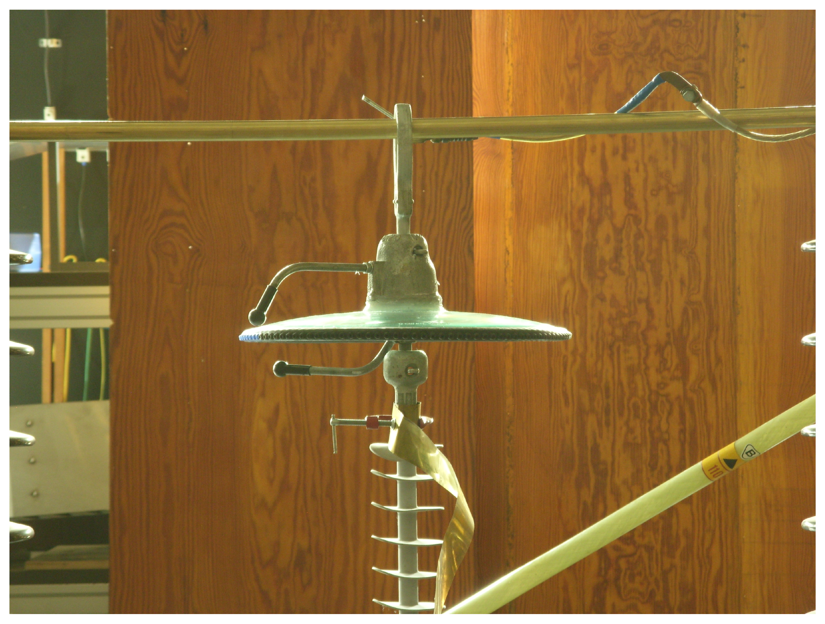
Due to the lack of common impact characteristics for this type of equipment, it was decided to develop such attributes for the two polarities for the MCA device using a four-stage lightning generator. The MCA test system to build the impact characteristic is shown in
Figure 4. In this regard, in order to test the strength of the system (
Figure 5), measurements were made for three distances between the multi-chamber system and the electrode: 20 mm, 30 mm and 40 mm.
3. Results
The principle of operation is best illustrated by the case when a surge current waveshape of 8/20 µs is applied to the device under laboratory conditions. As a result, we managed to receive the process of developing the discharge by debiting the MCA installed around the single insulator.
A lightning voltage impulse of 1.2/50 µs was applied to develop impact characteristics for the tested device under laboratory conditions. Examples of oscillograms of such waveforms for positive and negative polarities are shown in
Figure 6 and
Figure 7.
Figure 8 and
Figure 9 compare the above waveforms with the waveforms that were obtained in the LFA. It can be concluded that the waveforms after the discharge for MCA have larger deviations. This can be explained by the presence of a larger number of electrodes and the placement of them in the device. In contrast, LFA, due to the course of the discharge on the surface of the device and the presence of only a few electrode pairs, has a more straight path after the flashover.
Taking into account the above results, using the top-down method, we developed 50% of the MCA voltage from the length of the spark gap for the two polarities, assuming that
C;
kPa and a relative humidity of 43% (
Figure 10).
This characteristic shows that for a non-large distance (up to 20 cm) between the conductor and the surge protection device, the polarity does not affect the value of 50% of the impact strength. However, as the electrode gap increases, polarity’s effect is more and more noticeable. It is visible that at larger distances (above 40 mm) between the electrodes in the spark gap, the value of 50% of the impact strength is even 20 kV higher than the value of 50% of the impact strength with the positive polarity. Additionally, charts for the impact strength characteristics of MCA for two polarities were developed. Measurement of voltage breakdown was done with up and down method for twenty impulses at
C;
kPa and relative humidity of 43% (
Figure 10). An exemplary graph of such a characteristic for a distance of a spark gap of 20 mm is shown in (
Figure 11).
This characteristic will be helpful when evaluating the MCA’s specifications and comparing its parameters with other overvoltage protection devices. This characteristic shows that the voltage decreases with time gently. However, the characteristics are high enough.
4. Discussion
The comparison of the MCA device with other overvoltage protection devices can be made based on the following criteria:
Let us assume that classic systems such as lightning conductors and surge arresters were analyzed. Such solutions are attractive for newly built lines that are adapted to this type of surge protection. Installation difficulties arise in the case of existing lines that are not adapted to such types of surge protection. The value of such solutions is high, but in the case of the lightning rod, there is no need for maintenance and the surge arrester requires regular inspections, which increase the cost of this type of solution.
In the case of new solutions such as LFA or MCA, it should be noted that only MCA protects the line against a direct lightning strike. Installing these two types of devices is easy, regardless of whether they are existing or new lines. The effectiveness of protection of these devices, taking into account the limitations of MCA, is high, comparable to that of the surge arrester. Higher efficiency can only be ensured by installing a lightning conductor and surge arrester simultaneously. The cost of these devices is lower than the surge arrester and the lightning conductor because these devices, among other things, are less demanding during use/exploitation on the overhead line.
The above analysis shows that the MCA device is the most universal. However, it still requires more thorough analysis, testing, and possible improvement based on the research done in this article.
The results of these tests show that in the field of equipment refinement, one should focus primarily on such aspects as lowering the strength level of these devices, simplifying the construction, and ensuring easier gas extraction as a result of arcing in the chamber.
The effectiveness of the overvoltage protection device depends on its selectivity to the isolator, i.e., the discharge on this device must take place earlier than on the insulator. Therefore, a simplified form the speed of development of the discharge channel on the surface of the surge protection device should be analyzed; the analysis can be made based on the voltage-s-time characteristic of this device (
Figure 12 and
Figure 13).
In this case, the average speed of the development of the discharge channel can be determined from Equation (
1).
where
—the length of the discharge channel; and
t—discharge time. We assume that the speed of development of the discharge channel depends on the steepness of the voltage
a. Using estimated voltage–time characteristics of the LFA and the MCA through Equation (
2), which are shown in [
20], the speed of discharge development on LFA and MCA can be determined based on the following final Equation (
2).
In this case, the average speed of the channel in the LFA can be determined from Equation (
3).
where
b,
a—coefficients of approximation of the voltage and time characteristics of the LFA and the MCA. We assume the devices are under the influence of a impulse voltage 1.2/50 µs with an amplitude of 100 kV. As a result, comparable values of approximation factors for the analyzed devices were obtained. Therefore, the speed of lightning development on these devices is comparable. From the results we get, the time to discharge is much higher and shorter in the case of negative polarity.
Laboratory tests, in which the up-and-down method was used, were performed and a series of pulses for voltage–time characteristics were also applied. For the up-and-down method used to determine 50% breakdown discharge voltage, 20 standard lightning impulses were applied. The voltage–time characteristic five series of impulses with different voltage levels for each series were obtained and then applied. Then, the average values of measured maximum voltage and time to chopping were calculated (
Figure 14 and
Figure 15).
By analyzing the voltage–time characteristics of the LFA and the MCA, it concluded that the MCA characteristics lie above the LFA characteristics in the positive polarity range. However, for the negative impulse polarity, the situation is similar.
In addition,
Figure 14 and
Figure 15 show the comparison of the 50% breakdown discharge voltage of the LFA and the MCA. For the positive polarity, 50% of voltages for all tested distances are greater. However, in the case of negative polarity, the situation is variable; for MCA 50%, the breakdown voltage of the discharge is greater when the distance between the electrodes is 25 mm. When analyzing the above results, it should be remembered that they are burdened with some error because they are based on the probability of discharge at a given moment.
5. Conclusions
The results obtained in the framework of this article have significantly increased the knowledge in the field of assessing the possibility of using a new method of overvoltage protection, which is a new type of spark gap based on the MCA multi-chamber system and LFA. The research conducted obtained the following results:
In a laboratory setting, a system was created that ensured effective development of the MCA and LFA discharge as a result of applying a conducted surge,
Based on the analysis of recorded images of the waveform of voltage lightning impulse, the LFA and MCA devices were compared. From the conducted analysis, it can be concluded that the shape of the waveform depends on the surge discharge method and the presence of electrodes.
Parameters that ensure the effective operation of MCA and LFA have been defined. These parameters are presented based on the dependence of 50% of the impact strength of the considered system on the size of the spark gap, which allows for coordination of the strength of the analyzed overvoltage protection device and isolator.
On the basis of tests in laboratory conditions, the MCA and LFA impulse strength characteristics were developed; this is one of the criteria for assessing the effectiveness of surge protection devices.
These tests will enable the development of a more precise numerical model of selected elements of the device and comparison of the obtained results in the laboratory with simulations. Correlation of the results will allow for greater involvement in work on possible improvements to these devices and increase efficiency by first making appropriate changes to numerical models, and then by developing prototypes of modified/new devices.
Author Contributions
Conceptualization, M.B.; Writing—original draft, M.B.; Writing—review & editing, M.C.; Project administration, M.B.; Funding acquisition, M.B. and M.C. All authors have read and agreed to the published version of the manuscript.
Funding
The article was written as part of the internal grant “Testing of selected measures protection of overhead lines against atmospheric surges”, University of Warsaw Technology supporting scientific activity in the disciplines of Automation, Electronics and Electrical engineering.
Acknowledgments
The article was written as part of the internal grant “Testing of selected measures protection of overhead lines against atmospheric surges”, University of Warsaw Technology supporting scientific activity in the disciplines of Automation, Electronics and Electrical engineering.
Conflicts of Interest
The authors declare no conflict of interest.
References
- Flisowski, Z. Technika Wysokich Napięć; Wydawnictwa Naukowo-Techniczne: Warszawa, Poland, 1988. [Google Scholar]
- Anderson, R.B. Lightning parameters for engineering application. Electra 1980, 69, 65–102. [Google Scholar]
- Xia, Q. Research on Real-Time Risk Assessment of Transmission Line Lightning Strike and Trip Warning Model; South China University of Technology: Guangzhou, China, 2019. [Google Scholar]
- Banjanin, M. Line arresters and underbuilt wire application in lightning protection of 110 kV and 220 kV overhead transmission lines. In Proceedings of the 2019 18th International Symposium INFOTEH-JAHORINA (INFOTEH 2019), East Sarajevo, Bosnia and Herzegovina, 20–22 March 2019; pp. 1–5. [Google Scholar]
- He, J.; Yu, G.; Yuan, J.; Zeng, R.; Zhang, B.; Zou, J.; Guan, Z. Decreasing grounding resistance of substation by deep-ground-well method. IEEE Trans. Power Deliv. 2005, 20, 738–744. [Google Scholar] [CrossRef]
- Kohler, A. Earth Fault Clearing on an HV DC Transmission Line, with Special Consideration of the Properties of the DC Arc in Free Air. IEEE Trans. Power Appar. Syst. 1967, 3, 298–304. [Google Scholar] [CrossRef]
- Podporkin, G.V.; Enkin, E.Y.; Kalakutsky, E.S.; Pilshikov, V.E.; Sivaev, A.D. Overhead Lines Lightning Protection by Multi-Chamber Arresters and Insulator-Arresters. IEEE Trans. Power Deliv. 2010, 26, 214–221. [Google Scholar] [CrossRef]
- Wang, Q.; Sima, W.; Yang, Q.; Yuan, T.; Zhang, Z. Research on power frequency arc movement process of insulator in ring shape parallel gap lightning protection device. In Proceedings of the International Conference on Lightning Protection (ICLP), Shanghai, China, 11–18 October 2014; pp. 1158–1161. [Google Scholar]
- Washino, M.; Fukuyama, A.; Kito, K.; Kata, K. Development of current limiting arcing horn for prevention of lightning faults on distribution lines. IEEE Trans. Power Deliv. 1988, 3, 187–196. [Google Scholar] [CrossRef]
- Chino, T.; Iwata, M.; Imoto, S.; Nakayama, M.; Sakamoto, H.; Matsushita, R. Development of arcing horn device for interrupting ground-fault current of 77 kV overhead lines. IEEE Trans. Power Deliv. 2005, 20, 2570–2575. [Google Scholar] [CrossRef]
- Podporkin, G.V.; Enkin, E.Y.; Kalakutsky, E.S.; Pilshikov, V.E.; Sivaev, A.D. Development of multi-chamber insulator-arresters for lightning protection of 220 kV overhead transmission lines. In Proceedings of the International Symposium on Lightning Protection, Kathmandu, Nepal, 12–14 October 2011; pp. 160–165. [Google Scholar]
- Jia, W.; Sima, W.; Yuan, T.; Yang, M.; Sun, P. Optimization and experimental study of the semi-closed short-gap arc-extinguishing chamber based on a magnetohydrodynamics model. Energies 2018, 11, 3335. [Google Scholar] [CrossRef]
- Chusov, A.; Podporkin, G.; Pinchuk, M.; Ivanov, D.; Murashov, I.; Frolov, V. Development of a physical 2-D model for arc quenching chamber of lightning protection multichamber systems. In Proceedings of the 33rd International Conference on Lightning Protection (ICLP), Estoril, Portugal, 25–30 September 2016; pp. 1–9. [Google Scholar]
- Guo, Z.; Long, X.; Qian, Z.; Qiu, N. Three dimensional simulation of the arc inside an insulator-arrester with a multichamber system. AIP Adv. 2016, 6, 045117. [Google Scholar] [CrossRef]
- Borecki, M. A Proposed new approach for the assessment of selected operating conditions of the high voltage cable line. Energies 2020, 13, 5275. [Google Scholar] [CrossRef]
- Hoduń, P.; Borecki, M. Reliability Assessment of MV Power Connections. Energies 2021, 14, 6965. [Google Scholar] [CrossRef]
- Borecki, M.; Ciuba, M.; Kharchenko, Y.; Khanas, Y. Main aspects influencing the evaluation of atmospheric overvoltages in high-voltage networks. Bull. Pol. Acad. Sci. Tech. Sci. 2021, 69, e135838. [Google Scholar]
- Borecki, M.; Sobolewski, K. An elimination method for an emergency situation in Gas-insulated switchgear in power grids. IEEE Trans. Power Deliv. 2021, 36, 3724–3732. [Google Scholar] [CrossRef]
- Taniguchi, S.; Tsuboi, T.; Okabe, S.; Nagaraki, Y.; Takami, J.; Ota, H. Improved method of calculating lightning stroke rate to large-sized transmission lines based on electric geometry model. IEEE Trans. Dielectr. Electr. Insul. 2010, 17, 53–62. [Google Scholar] [CrossRef]
- Khalilov, F.H.; Evdokunin, G.A.; Polyakov, V.S.; Podporkin, G.V.; Tajibaev, A.I. Protection of Networks 6–35 kV from Surges; Energoatomizdat: Moscow, Russia, 2002. [Google Scholar]
- Li, J.; Shao, Q.; Zhou, M.; Zhao, Z.; Guo, J. Analysis of lightning discharge current and absorbed energy characteristics of lightning arresters in distribution network. Electr. Porcelain Arresters 2019, 139, 131–135. [Google Scholar]
- Borecki, M. Risk level analysis in the selected (initial) stage of the project life cycle. Manag. Prod. Eng. Rev. 2020, 11, 104–112. [Google Scholar]
- Pufal, I.V. Problematyka Projektowania Linii Napowietrznych z Przewodami Niepełnoizolowanymi 35 kV; SowZap ITC: Hong Kong, China, 2008. [Google Scholar]
- Borecki, M.; Kharchenko, Y. Comparative Simulation Analysis of Selected Medium and High Voltage Surge Protection Devices. Energies 2022, 15, 4326. [Google Scholar] [CrossRef]
- Podporkin, G.V.; En’kin, E.Y.; Pil’Shchikov, V.E. The development of multichamber arresters. Russ. Electr. Eng. 2013, 84, 1–5. [Google Scholar] [CrossRef]
- Liu, Y.; Wu, G.; Liu, K.; Guo, Y.; Zhang, X.; Shi, C. Study on the arc motion characteristics of multi-chamber arrester based on 3D model. IEEE Access 2020, 8, 90035–90041. [Google Scholar] [CrossRef]
- Sestasombut, P.; Ngaopitakkul, A. Evaluation of a Direct Lightning Strike to the 24 kV Distribution Lines in Thailand. Energies 2019, 12, 3193. [Google Scholar] [CrossRef]
| Disclaimer/Publisher’s Note: The statements, opinions and data contained in all publications are solely those of the individual author(s) and contributor(s) and not of MDPI and/or the editor(s). MDPI and/or the editor(s) disclaim responsibility for any injury to people or property resulting from any ideas, methods, instructions or products referred to in the content. |
© 2023 by the authors. Licensee MDPI, Basel, Switzerland. This article is an open access article distributed under the terms and conditions of the Creative Commons Attribution (CC BY) license (https://creativecommons.org/licenses/by/4.0/).


