Article

Numerical Research on the Jet-Mixing Mechanism of Convergent Nozzle Excited by a Fluidic Oscillator and an Air Tab

1
Research Center of Fluid Machinery Engineering and Technology, Jiangsu University, Zhenjiang 212013, China
2
Key Laboratory of Light-Duty Gas Turbine, Institute of Engineering Thermophysics, C.A.S., Beijing 100190, China
3
School of Aeronautics and Astronautics, University of Chinese Academy of Sciences, Beijing 100049, China
*
Author to whom correspondence should be addressed.
Energies 2023, 16(3), 1412; https://doi.org/10.3390/en16031412
Submission received: 21 December 2022 / Revised: 20 January 2023 / Accepted: 25 January 2023 / Published: 31 January 2023
(This article belongs to the Topic Advanced Engines Technologies)

Abstract

:
Unsteady numerical simulations, coupled with the SST (Shear Stress Transport) k-ω turbulence model, were conducted to study the mixing-enhancement characteristics of the excited jet generated by the fluidic oscillator and the air tab in a single channel convergent nozzle with an inlet total pressure of 140–200 kPa. Compared with the steady air-tab jet, the sweeping jet generated by the fluidic oscillator has roughly the same penetration in the main flow, but it can induce streamwise vortices and planar vortices of larger scale and longer duration, which is beneficial to enhance jet mixing efficiency in the range of 1.0 DN (DN represents the diameter of the main nozzle outlet) downstream from the main nozzle. When x > 1.0 DN, the jet mixing is mainly dominated by the shear layer between the main jet and the ambient. As the sweeping jet suppresses the expansion of the main jet, which reduces the contact area between the main jet and the ambient, its mixing efficiency is less than that of the air tab in this region. With the increasing inlet total pressure of the fluidic oscillator, the influence range of the sweeping jet is increased, but its mixing efficiency does not increase significantly. In general, the fluidic oscillator can use a small jet flow (<5%) to achieve a high mixing efficiency (i.e., 60% at x = 2.0 DN) at the expense of low total pressure loss (<2.3%), which indicates that it has good engineering applicability.

1. Introduction

A mixing method with high penetration and mixing efficiency can reduce the jet temperature and infrared radiation of an engine exhaust system, which is conducive to improving the overall performance of the engine. As an effective active mixing method, the formation and development of vortices in the transverse jet have been studied deeply by many researchers, using experimental and numerical methods [1,2,3,4]. After being injected into the main flow, the secondary flow is strongly mixed with the main flow due to the induced complex vortex structures near the jet hole, including shear-layer vortices, horseshoe vortices, wake vortices, and a counter-rotating vortex pair (CVP). Among these structures, the shear-layer vortex is induced by the Kelvin–Helmholtz instability (K–H instability) of the shear layer; the main flow boundary layer rolls up at the leading edge of the secondary jet and forms the horseshoe vortex at the root of the jet; the wake vortex is caused by the overturning, stretching, and diffusion of the crossflow boundary layer vortex; and the CVP, as the dominant factor affecting jet mixing, causes the secondary jet to lift up from the position close to the wall, which increases the scale of the vortex structure.
Kamotani et al. [5] studied the trajectory, velocity, and turbulence intensity of a single jet in a crossflow (JICF) and pointed out that the velocity ratio between the jet and the crossflow plays a decisive role in the flow mixing. New et al. [6] indicated that the change in the velocity ratio between the primary flow and the secondary jet had little effect on the mixing effect, while their increasing momentum ratio could significantly accelerate the flow mixing. They also compared the JICF with an elliptical exit with the JICF with a circular exit and found that the former produced two sets of CVPs, which helped to enhance the vortices’ interaction. Behrouzi et al. [7] compared the mixing effects of small-tab steady jets and pulsed transverse jets and studied the influence of the flow rate, the frequency, and the phase of the pulse transverse jets in detail. They found that the steady/unsteady JICF could induce a vortex similar to that of the CVP downstream from the small tab. Johari et al. [8] experimentally investigated the effect of pulse transverse jets with different frequencies and duty cycles on the flow mixing, and found that the pulse jets, which mainly produce the vortex rings, had a penetration that was significantly greater than that of the steady jets with the same velocity ratio. The penetration of pulse jets could reach five times of that of steady jets at 50 diameters downstream from the nozzle. Narayanan et al. [9] also showed that the pulsed transverse jets enhance jet instability and the strength of CVPs, resulting in a better mixing effect; the optimal mixing effect was achieved when the Strouhal number ranged from 0.1 to 0.26. Kamran et al. [10] reached similar conclusions when they studied the mixing enhancement of the pulsed jets under high-Reynolds-number conditions, and they further indicated that the periodic pressure, caused by the interaction between the turbulent fluctuating energy and the kinetic energy of vortex, was the main reason for the enhanced jet mixing. It can be seen that, compared with the steady jet, the unsteadiness of the pulsed jet affects the formation and development of the vortex structure in the flow field, which can further improve the mixing efficiency.
The traditional high-frequency pulsed jets often require complex control structures and control logic, so their reliability and robustness are not strong under harsh environmental conditions. In 1978, Stouffer [11] invented the fluidic oscillator, which could produce sweeping jets with adjustable frequency, without any moving parts. The fluidic oscillator consists of an inlet, a mixing chamber, two feedback channels, and an expansion outlet. Under the Coanda effect, the high-pressure fluid entering the oscillator’s interior adheres to the wall on one side at random; then, most of the fluid is ejected from its outlet, while the other part returns to the mixing chamber through the feedback channel, which drives the main fluid to move to the other side of its mixing chamber, thereby changing the direction of the outlet jet. In this way, a jet that sweeps repeatedly in a certain range is generated downstream from the fluidic oscillator. The jet had a very wide sweep frequency, ranging from 6 kHz to 22 kHz, and its sweep frequency was linear to its flow rate when its geometry parameters were determined [12]. Due to its simple structure and its strong robustness, the fluidic oscillator has been widely used for flow control [13], noise control [14], drag reduction [15], and film cooling [16].
There has been some research on the acceleration mixing of the fluidic oscillator. Nathan and Luxton [17] investigated the mixing characteristics of low-frequency sweeping jets with stationary air and indicated that the sweeping action of the jet is conducive to enhancing the macro mixing process between the jet and air, but it inhibited the formation of small-scale turbulence spots to some extent. Ostermann et al. [18,19,20] experimentally researched the three-dimensional time-resolved flow field under the interaction between the swept jet and the cross flow and found that the Strouhal number and the velocity ratio of the jet were the two important parameters affecting the flow field. As the velocity ratio increased, the penetration of the jet in the transverse and normal directions increased. In addition, they found that the oscillating jet could form a rotating vortex pair, and their rotation directions were opposite to that of the counter-rotating vortex pair formed by the steady jet. This vortex pair could destroy the jet structure, thereby promoting higher intense entrainment and mixing. However, compared to the steady jet, the velocity of the sweeping jet attenuated faster, so its trajectory in the cross flow was shallower. Lacarelle and Paschereit [21] indicated that the periodic sweeping jet enhanced the circumferential diffusion of the jet, which was conducive to promoting the macro- and micro-mixing process. Compared with the steady jet, the fluidic oscillator can reduce the mixing length by 50%. It can be seen that the research on flow mixing related to the fluidic oscillator was basically carried out in a low-speed crossflow, while research on high-speed jet mixing was rarely seen. In this paper, the fluidic oscillator and the air tab are applied to enhance the mixing of high-speed jets downstream from a convergent nozzle, and the flow-mixing mechanism and the influence of the inlet total pressure are analyzed in detail.

2. Numerical Method

The commercial ANSYS CFX solver is used to solve three-dimensional Reynolds-averaged Navier–Stokes (RANS) equations, and the shear stress transport (SST) k-ω two-equation turbulence model is used for turbulence closure [22,23]. The high order and second order backward Euler difference methods are adopted for the convection and time terms, respectively, and the residual targets of momentum, mass, energy, turbulence kinetic energy, and transition equations are set to 10−6.

2.1. Convergent Nozzle and Fluidic Mixer

The cross sections of the fluidic oscillator, the air tab, and the convergent nozzle used in this paper are shown in Figure 1. The height, width, and thickness of the fluidic oscillator were 13.2 mm, 7.0 mm, and 1.0 mm, respectively. The 3D model of fluidic oscillator was extruded 1.0 mm from the cross section, as shown in Figure 1a. Its inlet was 3.2 mm × 1.0 mm, the throat was 1.0 mm × 1.0 mm, and the outlet expansion angle was 100°. The research showed that this structure with the aspect ratio (i.e., the ratio of the width and the throat hydraulic diameter of the fluidic oscillator) of 1.0 could achieve maximum sweeping frequency when the inlet flow was the same [24]. The air tab is a round tube with a diameter of 0.96 mm and a length of 11.0 mm, and one air tab is installed in every 120º sector, as in the case of the fluidic oscillator. In this way, its flow rate can be ensured to be equal to that of the fluidic oscillator in all cases studied in this paper.
The model of the convergent nozzle is shown in Figure 1b: the inlet diameter is 37.5 mm, the outlet diameter is 30 mm, and the length of the nozzle is 43.5 mm with the converging angle of 11°. Three fluidic oscillators or air-tabs are uniformly set up at 2.0 mm upstream of the convergent nozzle outlet in the circumferential direction, respectively.

2.2. Boundary Conditions

In this paper, the calculation domain with a sector angle of 120° (Figure 2) was selected, including the internal flow field domain of the convergent nozzle, a fluidic mixer (such as a fluidic oscillator or an air tab), and the external domain downstream from the nozzle. The inlets of the fluidic mixers were extended by 10 mm to ensure the full development of the inlet boundary layer. The diameter of the far field downstream from the nozzle was 300 mm (10 DN—10 times of the nozzle outlet diameter) with a length of 450 mm (15 DN) to ensure that the jet diffusion and mixing were not disturbed. As shown in the coordinates in Figure 2, the origin of the coordinate system was located at the intersection of the middle cross section of the fluid mixers and the central axis of the main nozzle. All the inlets adopted the pressure inlet boundary conditions. For the main flow, the inlet total pressure was 120 kPa and its inlet total temperature was 875.9 K; for the secondary flow, the inlet total pressure was 140 kPa, 160 kPa, 180 kPa, and 200 kPa for different cases, respectively, and its inlet total temperature was 333 K; for the far field, the inlet total pressure was 101,325 Pa and its inlet total temperature was 288 K. The other boundaries of the far field were set as the opening boundary with a static pressure of 101,300 Pa and a static temperature of 288 K. Both sides of the calculation domain were set as rotation periodic boundaries, and the rest were solid walls without slip.
In the transient calculation of the fluidic oscillator, the time steps were 6 × 10⁻⁷ s, 4 × 10⁻⁷ s, 4 × 10⁻⁷ s, and 2 × 10⁻⁷ s when the inlet total pressure ranged from 140 kPa to 200 kPa. As a result, the root mean square values of the Courant numbers were certain to be less than 1.0 for all cases. The maximum number of internal cycles per time step was 12 for each dynamic calculation.

2.3. Grids Independence

Figure 3 shows the computation grid for the fluidic oscillator and the air tab. All computational domains were meshed by the hexahedral structured/unstructured grids. The fluidic oscillator as meshed by ANSYS MESH with the hexahedral structured grid, and the rest were meshed by ICEM.
In order to verify grid independence, three grids with 2.18 million, 4.36 million, and 8.60 million nodes, respectively, were selected for a comparative calculation of the fluidic oscillator with a inlet total pressure of 160 kPa. Figure 4 compares the total pressure coefficient distributions of the jet centerline for the cases with different grids. The total pressure coefficient distribution of the jet centerline calculated by the grid with 4.36 million nodes was not much different than that of the grid with 8.60 million nodes, and the maximum difference was less than 0.8%. In order to save the computing time, the grid with 4.36 million nodes was selected for subsequent numerical simulation in this paper. In this grid, the node numbers in the axial, radial, and circumferential directions of the whole calculation domain were 342, 78, and 124, respectively; the node numbers in the length, width, and thickness directions of the fluidic oscillator were 270, 66, and 18, respectively; the air tab was meshed by O-type grid and the circumferential and axial grid node numbers were 50 and 50, respectively. Due to the complex shape of the fluidic oscillator, it was meshed separately from the convergent nozzle. In this way, the GGI-type interface, whose grid is shown in the sub-graph marked with “interface” in Figure 3, was used for the data exchange between them.

2.4. Validation

Ostermann et al. [19,25] investigated the interaction between the crossflow and the oscillating jet with different velocity ratios. The velocity ratio (VR) was defined as:
V R = U f / U
where U f is the velocity at the throat of fluidic oscillator and U is the velocity at the crossflow inlet. The time-resolved experimental data of Ostermann were used to validate the calculation method in this paper, wherein the throat size of the fluidic oscillator was 10 × 10 mm, yielding a hydraulic diameter (D) of 10 mm, and the test section was a 550 × 550 mm square with a total length of 2500 mm. In the validation calculation, the inlet velocities of the fluidic oscillator and the main flow were consistent with their test conditions. Figure 5 compares the calculated and measured results of the sweeping jet frequency under different velocity ratios. The sweeping jet frequency was obtained by a series of static pressure monitoring points arranged downstream from the fluid exciter throat. Compared with the experimental results, the maximum error between the numerical and experimental results was not more than 3.5%, which indicated that they were basically consistent. Figure 6 shows experimental and computational velocity contours and vectors of different phases at x/D = 14 for the case of VR = 3, where the origin of the x-axis is located at the middle section of the fluid exciter and D is the hydraulic diameter of the fluid oscillator throat. It can be seen that the calculated results of velocity distribution and the position and sizes of the vortices on this section, under different phases, are in good agreement with the experimental results. The above discussion shows that the numerical method adopted in this paper can accurately simulate the complex flow field inside the fluidic oscillator.

3. Results and Discussion

3.1. Mechanism of Fluidic Mixer

Figure 7 shows the instantaneous flow field inside the fluidic oscillator at four phase positions during a half-sweeping cycle with an inlet total pressure of 140 kPa, and compares it with that of the steady air tab. In this paper, the phase with φ = 0° was defined as the moment at which the jet entered the main flow from the left extreme boundary of the oscillator exit. At the φ = 0° phase, the jets attached to the right wall of the mixing chamber, and most of them entered the throat through the right side of the mixing chamber and sprayed into the main flow, while a small amount of the jets entered the right feedback channel driven by vortex V3 on the left, and this feedback flow in turn pushed the main jet to move to the left at the entrance of the mixing chamber, thus gradually forming a separation vortex V1 on the right side of the mixing chamber. As this separation vortex increased (e.g., φ = 30°–180°), the main jet inside the mixing chamber was gradually pushed to the left wall, the separation vortex V2 on the left wall was reduced, and the vortex V3 on the left side of the throat was also continuously squeezed. When φ = 180°, the vortex V1 developed to its maximum scale: on the one hand, it basically blocked the right feedback channel; on the other hand, it pushed the flow in the mixing chamber close to the wall on the left side, which made the separation vortex V2 on the left side squeeze to its minimum scale. Finally, the main jet entered the throat from the left side and ejected into the main flow from the right side, realizing the conversion of the main jet direction. At the same time, the vortex V3 blocking the left feedback channel was squeezed out of sight, resulting in a portion of the jet entering the left feedback channel. With the enhancement of this feedback flow on the left side, the jet in the mixing chamber was driven to move toward the right wall. Finally, an unsteady jet sweeping back and forth was formed at the outlet of the fluidic oscillator.
It can be seen that the vortex V3 upstream from the throat and the vortex V4 (not shown here) at its opposite side have two functions: on the one hand, they jointly drive the sweeping of the jet, thus controlling the direction of the outlet jet; on the other hand, they also control the flow entering the feedback channel, so as to indirectly control the size of the separation vortex in the mixing chamber and the frequency of the outlet sweeping jet. Compared with the steady jet of the air tab, the influence range of the fluidic oscillator’s jet in the circumferential direction was qualitatively larger, due to its left–right sweeping characteristics. For the radial penetration of the jet, the penetration of the sweeping jet was slightly lower than that of the air tab only at the phase of φ = 30° (as shown in Figure 6), and the penetrations at other phases are basically the same as the latter; some of them have even increased.
When the sweeping jet ejected into the main flow, the streamwise vortices, induced at the boundary of the main flow, were among the important factors accelerating the mixing. Figure 8 shows the streamwise vorticity distribution of the sweeping jet at different phases and different axial sections for the case with the inlet total pressure of 140 kPa, and compares it with that of the steady air tab. After the sweeping jet entered the main flow, it induced the formation of a pair of streamwise vortices, as shown by VR and VL in Figure 8. As shown by the four phases in Figure 7, the jet’s outlet position gradually changed from the left side of the fluidic oscillator’s exit to the right side, and the jet direction also changed accordingly. When the jet entered the main stream from the left side (such as φ = 0° and 30°), it could be observed that the vortex VL was obviously smaller than the vortex VR in peak magnitude and vortex size (as shown in the axial sections x = DN/6–DN/2 in Figure 8). This may have been because the development of the VL was restrained by the double constraints of the left-leaning jet and the nozzle wall. However, in the downstream flow development, the stronger vortex VR dissipated faster and was exhausted at x = 5 DN/6, where the vortex VL further developed without the nozzle constraints. As the jet entered the main flow almost vertically (i.e., φ = 150°), the VR and VL had roughly the same peak magnitudes and scale (as shown in section x = DN/2).
As the jet entered the main stream from the right side (i.e., φ = 180°), the situation was exactly the opposite to that of the left side. At x = DN/3–DN/2, the peak magnitude and scale of the VL were larger than those of the VR, and the VR developed further at x = 5 DN/6 where the VL was almost exhausted. Compared with that of the steady air tab, the peak vorticity of the streamwise vortices induced by the fluidic oscillator was lower in each phase. The peak vorticity of the air tab was 11.0, and that of fluidic oscillator was 10.1. However, compared with the streamwise vortex range shown by the streamline, it was found that the streamwise vortex scale of the sweeping jet was obviously larger than that of the steady jet. At x = 5 DN/6, the streamwise vortices induced by the air tab were completely dissipated, while the streamwise vortices induced by the fluidic oscillator still had a distinct structure in each phase, which suggests that the latter lasts longer. Under the same inlet conditions, the peak streamwise vorticity of the steady air-tab jet was higher than that of the sweeping jet, while the sweeping jet had a streamwise vortex pair with a larger scale and a longer duration. Therefore, further study is required to determine which kind of jet is more conducive to accelerating jet mixing.
The azimuthal vorticity, as the sum of the vorticity on the section perpendicular to the streamwise direction, can represent the strength of planar vortices; therefore, it can also characterize the intensity of small-scale mixing to a certain extent. Figure 9 shows the azimuthal vorticity distribution of the sweeping jet at different phases and different axial sections for the case with the inlet total pressure of 140 kPa and compares it with that of the steady air-tab jet. The jet at the outlet of the fluidic oscillator and the vortices on its left and right sides (V5 and V6 in Figure 7) distorted the planar vortices band downstream from the main nozzle, and the deflection direction of the planar vortices band at different phases was consistent with the direction of the sweeping jet (as shown on the axial section x = DN/6 in Figure 9). Compared with that of the steady air tab, the peak azimuthal vorticity of the sweeping jet did not increase significantly, but its radial and circumferential scale increased, especially the latter. Moreover, this difference became greater with the development of jet mixing. This means that sweeping jets with larger planar vortices can be more conducive to promoting small-scale mixing. At x = 5 DN/6, the residual azimuthal vorticity downstream from the air tab was significantly smaller than that of the fluidic oscillator at each phase, which indicated that the planar vortices induced by the steady air-tab jet dissipated more rapidly. The planar vortices downstream from the two fluidic mixers were almost dissipated completely on the axial section x = 1.0 DN. Combined with the above analysis on the streamwise vortices, the following conclusion could be inferred: the action regions of the streamwise vortices and planar vortices induced by the two jets were confined to the range of 1.00 × DN downstream from the nozzle.
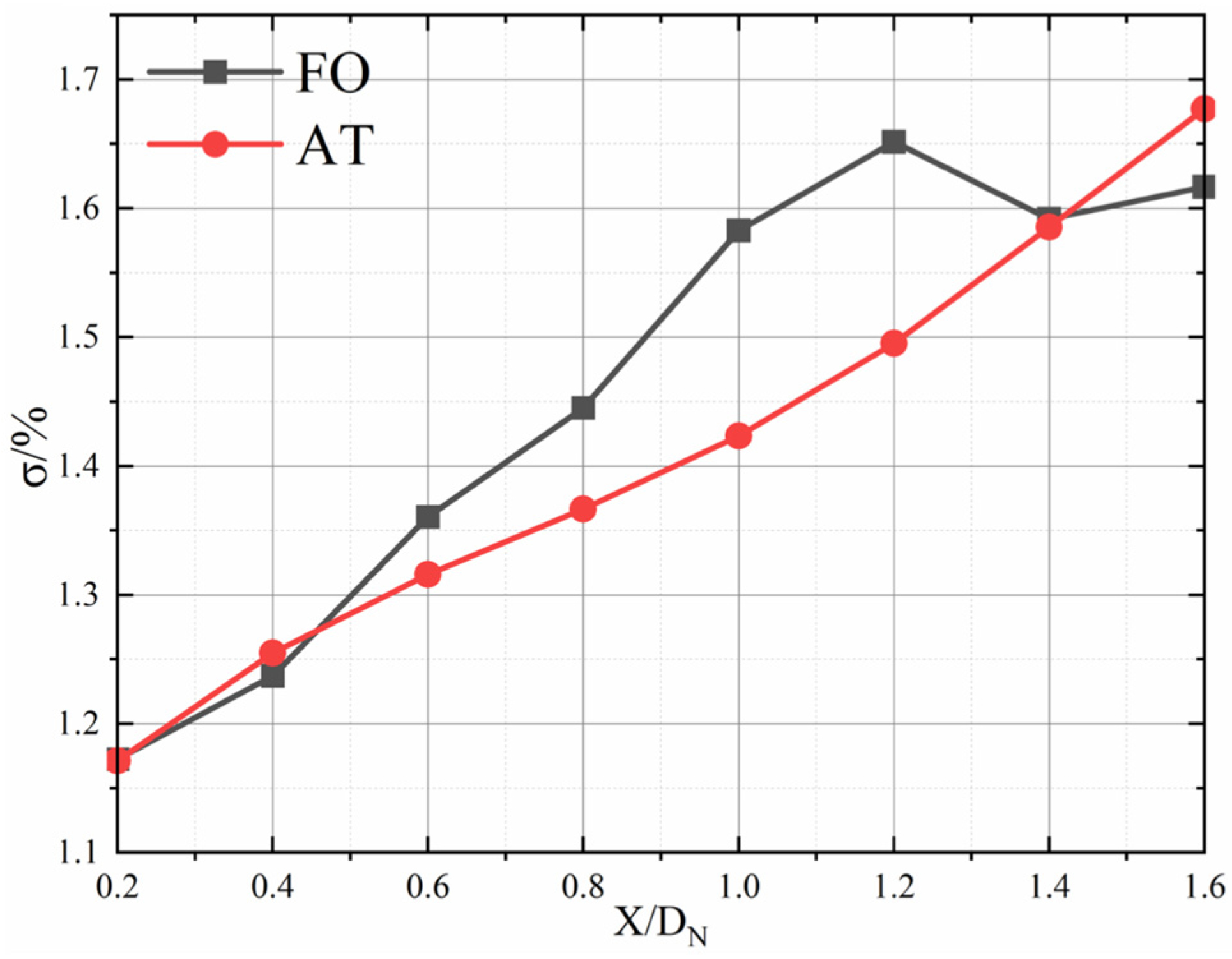
Figure 10 compares the jet-mixing efficiency and the expansion radius of the two fluidic mixers downstream from the nozzle when the inlet total pressure is 140 kPa. The mixing efficiency is defined as follows:
η = m Δ m i ¯ T 0 , i ¯ m N ¯ T 0 , N ¯ m f ¯ T 0 , f ¯ ( m N ¯ + m f ¯ ) T 0 , u ¯ m N ¯ T 0 , N ¯ m f ¯ T 0 , f ¯
where m ¯ and T 0 ¯ are the time-averaged mass flow and total temperature, respectively, Δ m i ¯ is the time-averaged mass flow through point i of the calculation section, and the subscripts N, f, and u represent the inlet of main nozzle, the inlet of fluidic exciter, and the uniformly mixed section (i.e., x = 9.8 DN section downstream of the main nozzle in this paper), respectively. In the range of x = 0.2 DN–0.8 DN, the mixing efficiency of the sweeping jet was higher than that of the steady air-tab jet. Based on the above conclusion, the flow mixing in this axial range is dominated by the streamwise vortices and planar vortices, which means that the vortices induced by the fluidic oscillator are more conducive to enhancing jet mixing than those induced by the air tab. This is consistent with the above comparative-analysis conclusion of the streamwise vortices and planar vortices. However, the jet-mixing efficiency downstream from the air tab exceeded that of the fluidic oscillator when x > 0.8 DN. At this time, the streamwise vortices and planar vortices downstream from the two fluidic mixers were completely dissipated, and the shear layer between the main flow and the surrounding air was the dominant factor for jet mixing. The expansion radius is defined as the section with twice the mass flow of inlet (including nozzle inlet and fluidic mixer inlet) downstream from the nozzle. Two times the inlet mass flow is an empirical value, below which the outer contour of the jet is not circular, and above which the influence on this radius of the inlet parameters will be weakened. To a certain extent, this radius can represent the boundary affected by the jet and quantitatively characterize the contact area between the jet and the surrounding air. It can be seen that the jet expansion radius decreased first and then increased, which indicated that the jet converged first and then expanded, due to the influence of the nozzle convergence angle. Compared with the steady air-tab jet, the jet radius with the equal mass flow of the sweeping jet converged faster in the jet convergence stage and was smaller than that of the air tab on the same axial section in the jet-expansion stage. This shows that the sweeping jet can restrain the expansion of the main jet in the case with the fluidic oscillator, thus making the contact area between the main flow and the surrounding air smaller than that of the air tab. Therefore, the mixing efficiency of the fluidic oscillator was smaller than that of the air tab for the region with x > 0.8 DN, where the shear layer dominated the jet mixing between the cross- and the surrounding air. In the same way, for the region (0 < x < 0.8 DN), where the streamwise vortices and the planar vortices dominated the jet mixing, the mixing effect of the shear layer between the main stream and the surrounding air in the case with the fluidic oscillator was actually lower than that of the air tab., This in turn suggested that, compared with the case with the air tab, the mixing efficiency gain brought about by the streamwise vortices and the planar vortices in the case with the fluidic oscillator was a little higher than that shown in Figure 10.
Figure 11 compares the mixing loss distribution of the two fluidic mixers for the cases with the inlet total pressure of 140 kPa. The mixing loss is defined as follows:
σ = 1 - m P 0 , i ¯ m P 0 , N ¯ + m P 0 , f ¯
where P 0 ¯ is the time-averaged total pressure and the subscripts N, f, and i represent the inlet of main nozzle, the inlet of fluidic exciter, and the point i of the calculation section. For the steady air-tab jet, the curve of mixing loss changed linearly with the axial distance. When x < 1.2 DN, the mixing loss of the sweeping jet also increased linearly and the total pressure loss was greater than that of the steady air-tab jet. For the region of x < 0.8 DN, the higher mixing loss of the fluidic oscillator was mainly related to its greater mixing efficiency, but the increment of the mixing loss was not proportional to the increment of the mixing efficiency, which may have been due to the additional loss caused by the high internal flow loss of the fluidic oscillator itself. For the region of 0.8 DN < x < 1.2 DN, the mixing efficiency of the fluidic oscillator was decreased, but the cumulative total pressure loss in the prior period was high, which made the loss in this region keep growing. In the region of 1.2 DN < x < 1.6 DN, the mixing loss of the fluidic oscillator was approximately stable, and the total pressure loss of the air tab surpassed that of the fluidic oscillator, due to the improvement of its mixing efficiency.

3.2. Influence of Inlet Total Pressure

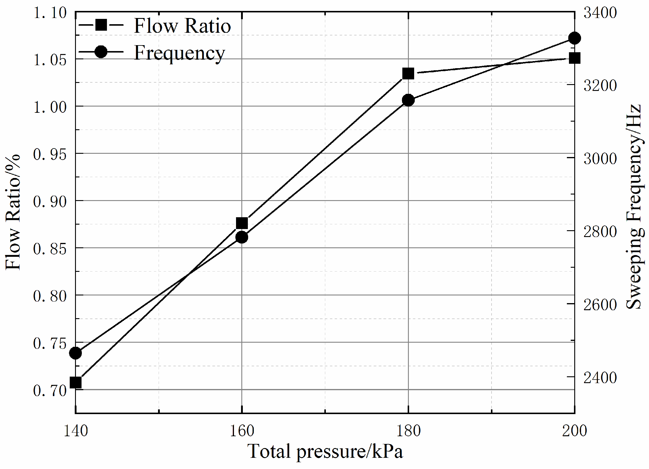
Figure 12 shows the mass flow ratio and the sweeping frequency of the fluidic oscillator for various inlet total pressures. With the increasing inlet total pressure of the fluidic oscillator, its mass flow rate and sweeping frequency increased linearly. On the other hand, it was not difficult to find that the sweeping frequency also increased linearly with the jet flow rate, which was consistent with the findings of previous works [12]. When the inlet total pressure reached 200 kPa, the flow rate increased by only 0.02%, compared with the case of 180 kPa. The reason was that the throat of the fluidic oscillator reached the critical state in this case, and increasing the inlet total pressure could no longer further increase the mass flow rate of the fluidic oscillator. However, the increase in the inlet total pressure could obviously affect the sweeping frequency of the fluidic oscillator.
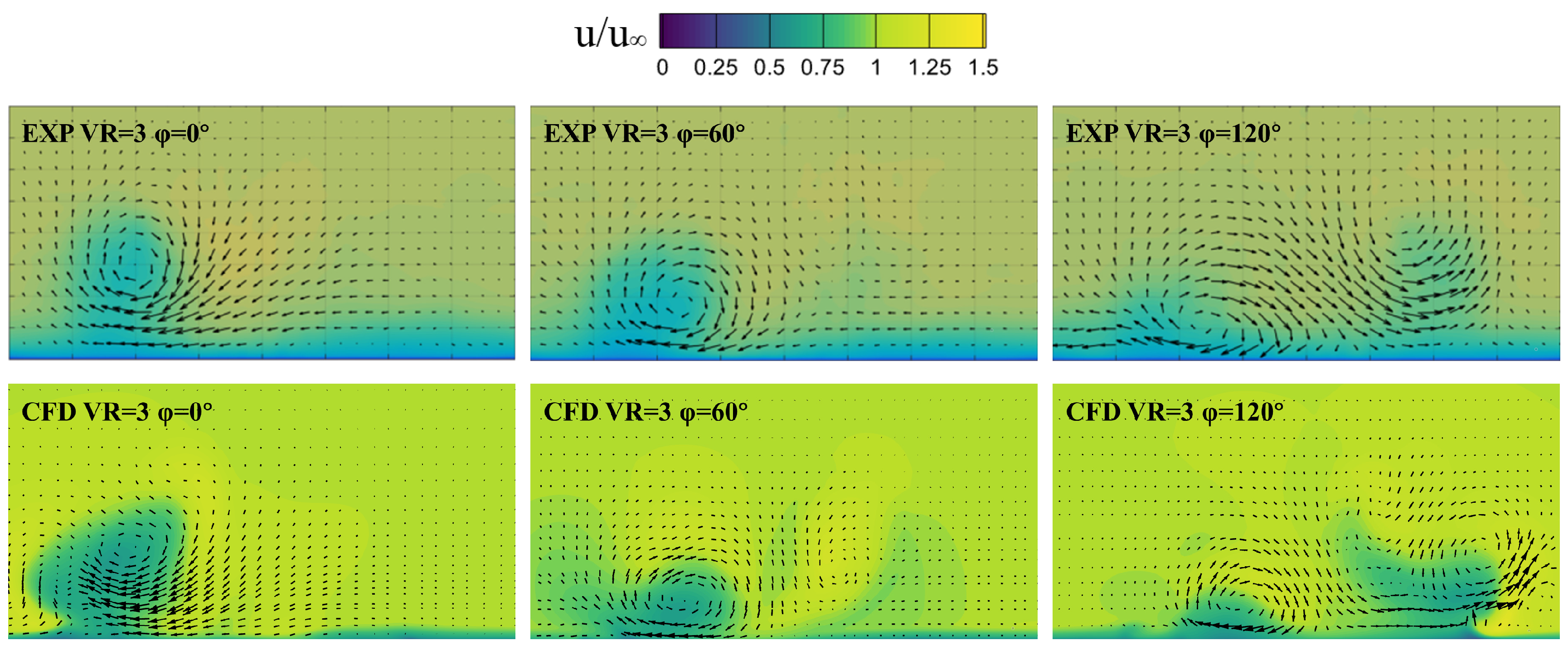
Figure 13 shows the contours of time-averaged velocity at the central section of the two fluidic mixers for cases with different inlet total pressures. With the increase in the inlet total pressure, there was no obvious change in the left and right boundaries of the sweeping jet, while the time-averaged penetration increased. Moreover, the low-velocity region influenced by the sweeping jet developed from an initial semi-circle to a fuller rounded rectangle; that is, the area of this region increased. These developments indicated that the increase in the inlet total pressure enlarged the influence range of the sweeping jet to some extent. For the steady air-tab jet, the penetration increased with the increasing inlet total pressure, causing its influence region to be farther and farther away from the nozzle, but its influence range did not increase significantly. Under the same inlet total pressure, the time-averaged penetration of the sweeping jet was basically the same as that of the steady air-tab jet, but the circumferential influence range of the sweeping jet was significantly larger than that of the steady air-tab jet, and this difference increased with the increase in the inlet total pressure.
The length of the potential core region can directly reflect the mixing efficiency between the main jet and the ambient air. 
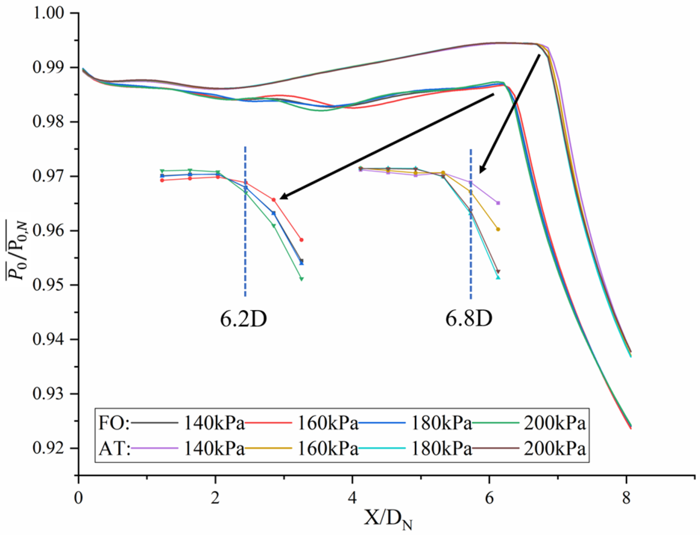
Figure 14 compares the total pressure distribution of the central line downstream from the main nozzle for the two fluidic mixers in cases with different inlet total pressures. In the region of x < 1.0 DN, where the streamwise vortices and planar vortices dominant the jet mixing, the following observations were possible (1) the greater the inlet pressure, the faster the attenuation rate of the total pressure for the two fluidic mixers, and (2) the total pressure attenuation rate of the fluidic oscillator was greater than that of the air tab under different inlet total pressure conditions. When 1.0 DN < x < 4.0 DN, the attenuation rate of the total pressure along the centerline downstream from the fluidic oscillator still increased with the increase in the inlet total pressure, but it remained the same in the case with an inlet total pressure of 140 kPa (a slight increase in appearances may have been related to numerical errors). With the continuous mixing between the main jet and the surrounding air, the total pressure of the potential core region downstream from the fluidic oscillator started to decrease gradually at x = 6.2 DN for all cases; that is, the length of the potential core region was 6.2 DN for all cases. In order to ensure that the fluidic oscillator was not blocked, the narrow inlet total pressure variation range (140–200 kPa) selected in this paper was the main reason for its small impact on the potential core-region length. For the actual nozzle, by increasing the size of the fluidic oscillator’s throat, the inlet total pressure could be further increased to improve the mixing efficiency, but it led to the problem of a too-large fluidic oscillator and a too-high mass flow ratio. This needs further study and clarification. For the air tab, the length of the potential core region was about 6.8 DN, which was greater than that of the fluidic oscillator. This suggests that the mixing effect of the sweeping jet is better than that of the steady air-tab jet under the same inlet total pressure.
Figure 15 compares the total pressure loss of the two fluidic mixers for cases with different inlet total pressures. With the increase in inlet total pressure, the total pressure loss of the two fluidic mixers showed an approximately linear growth trend. Compared with the air tab, the total pressure loss of the fluidic oscillator was larger, and this difference increased with the increasing inlet total pressure. The increasing total pressure loss of the fluidic oscillator was related to its greater mixing efficiency, and it was also influenced by its higher internal flow loss. Overall, the fluidic oscillator can use a small jet flow (<5%) to achieve a high mixing efficiency (i.e., 60% at x = 2.0 DN) at the expense of low total-pressure loss (<2.3%), which indicates that it has good engineering applicability.

4. Conclusions

In this paper, the mechanism and characteristics of flow mixing in a single-channel convergent nozzle enhanced by a fluidic oscillator and an air tab were studied by numerical simulation under four inlet total pressure conditions. Through the detailed analysis on the internal flow field of the fluidic oscillator, this paper further clarified the formation mechanism of the excitation sweeping jet and pointed out that the vortex near the entrance of the fluidic oscillator’s throat, which can control the direction of the outlet jet and the mass flow rate of the feedback channel, is an important factor influencing the frequency of the sweeping jet. The vortex pairs induced by the sweeping jet had obvious asymmetric properties: when the jet entered the main stream from the left side, the peak vorticity and scale of the left streamwise vortex were obviously smaller than those of the right one due to the dual constraints of the sweeping jet and the nozzle wall; similarly, the peak vorticity and scale of the right streamwise vortex were obviously smaller than those of the left one when the jet entered from the right side. Compared with the symmetrical streamwise vortices and planar vortices induced by the steady air-tab jet under the same inlet conditions, the vortices induced by the sweeping jet had approximately the same peak vorticity but a larger scale and a longer duration. When 0 < x ≤ 1.0 DN, the vortices induced by the two fluidic mixers dominated the jet mixing, and the mixing efficiency of the fluidic oscillator was significantly higher than that of the air tab in the cases with the same inlet conditions. When x > 1.0 DN, these vortices mentioned above had basically been exhausted, and the vortex of the shear layer between the main jet and the surrounding air came to dominate the jet mixing. As the sweeping jet of the fluidic oscillator inhibited the expansion of the main jet, which reduced the contact area between the main stream and the surrounding air, the jet mixing efficiency of the fluidic oscillator was lower than that of the air tab.
The penetration and influence range of the two kinds of jets in the main flow increased with the enhancing inlet total pressure. Under the same inlet conditions, the penetration of the sweeping jet was approximately the same as that of the steady air-tab jet, but its influence range was larger than that of the latter, and this difference increased with the enhancing inlet total pressure. As the throat of the fluidic oscillator restricted the increase in its inlet total pressure, the influence of its inlet total pressure on the mixing efficiency was not obvious within the scope of this paper. However, with the increase in the inlet total pressure, the mixing loss of the sweeping jet obviously increased, which may have been related to the increase in the flow loss inside the fluidic oscillator. The inlet total pressure range of the fluidic oscillator could be increased by increasing the size of the throat, which was conducive to further improving the mixing efficiency and could also lead to the problems of a too-large fluidic oscillator and a too-high mass flow ratio.
Overall, the fluidic oscillator can use a small jet flow (<5%) to achieve a high mixing efficiency (i.e., 60% at x = 2.0 DN) at the expense of low total pressure loss (<2.3%), which indicates that it has good engineering applicability.

Author Contributions

Conceptualization, M.L.; methodology, Y.Z.; validation, Z.L.; formal analysis, H.D.; investigation, X.O.; supervision, X.L., G.X. and J.Z. All authors have read and agreed to the published version of the manuscript.

Funding

This research was funded by the “National Science and Technology Major Project (J2019-II-0007-0027)” and by the “Science Center for Gas Turbine Project (P2022-DC-II-001-001)”.

Institutional Review Board Statement

Not applicable.

Informed Consent Statement

Not applicable.

Data Availability Statement

Not applicable.

Conflicts of Interest

The authors declare no conflict of interest.

Nomenclature

AT:Air tabP0,f:Total pressure at fluidic exciter inlet, kPa
BR:Velocity ratioP0,N:Total pressure at nozzle inlet, kPa
Cwa:Azimuthal vorticity, C w y 2 + C w z 2 Re:Reynolds number, (U Dh/υ)
Cws:Streamwise vorticitySt:Strouhal number, (f Dh/υ)
Cwy:Vorticity Coefficient in y directionT0:Total temperature at sections, K
Cwz:Vorticity Coefficient in z direction T0,f:Total temperature at fluidic exciter inlet, K
D:Throat hydraulic diameter, mT0,N:Total temperature at nozzle inlet, K
Dh:hydraulic diameter, mU:local mean velocity, m/s
DN:Nozzle outlet diameter, mυ:kinematic viscosity, m2/s
f:Frequency, HzVR:Velocity ratio
FO:Fluidic oscillatorx:Axial coordinate
m:Massflow, kg/sy+:Non-dimensional wall distance
mf:Massflow at fluidic exciter inlet, kg/sφ:Phase angle
mN:Massflow at nozzle inlet, kg/sσ:Total pressure loss coefficient
P0:Total pressure, kPaTime-averaged

References

  1. Moussa, Z.M.; Trischka, J.W.; Eskinazi, S. The near field in the mixing of a round jet with a cross-stream. J. Fluid Mech. 1977, 80, 49–80. [Google Scholar] [CrossRef]
  2. Fric, T.F.; Roshko, A. Vortical structure in the wake of a transverse jet. J. Fluid Mech. 1994, 279, 1–47. [Google Scholar] [CrossRef] [Green Version]
  3. Li, W.; Jiang, G.Q.; Zhang, X.Y. Vortex structures of round turbulent jets in cross-flow. Adv. Water Sci. 2003, 5, 576–582. [Google Scholar]
  4. Zhang, Y. Experimental and numerical investigations on the vortical structures of an impinging jet in crossflow. J. Shanghai Univ. 2006, 3, 279–280. [Google Scholar] [CrossRef]
  5. Greber, I.; Kamotani, Y. Experiments on a turbulent jet in a cross flow. AIAA J. 1972, 10, 1425–1429. [Google Scholar]
  6. New, D. Topological Studies of Circular and Elliptic Jets in a Cross Flow. Ph.D. Thesis, National University of Singapore, Singapore, 2004. [Google Scholar]
  7. Behrouzi, P.; McGuirk, J. Flow control of jet mixing using a pulsed fluid tab nozzle. In Proceedings of the 3rd AIAA Flow Control Conference, San Francisco, CA, USA, 5–8 June 2006. Paper No. AIAA 2006-3509. [Google Scholar]
  8. Johari, H. Scaling of fully pulsed jets in crossflow. AIAA J. 2006, 44, 2719–2725. [Google Scholar] [CrossRef]
  9. Narayanan, S.; Barooah, P.; Cohen, J.M. Dynamics and control of an isolated jet in crossflow. AIAA J. 2003, 41, 2316–2330. [Google Scholar] [CrossRef]
  10. Kamran, M.A.; McGuirk, J.J. Subsonic jet mixing via active control using steady and pulsed control jets. AIAA J. 2011, 49, 712–724. [Google Scholar] [CrossRef]
  11. Stouffer, R.D. Oscillating Spray Device. U.S. Patent 4,151,955, 1 May 1979. [Google Scholar]
  12. Gregory, J.W.; Sullivan, J.P.; Raman, G.; Raghu, S. Characterization of the microfluidic oscillator. AIAA J. 2007, 45, 568–576. [Google Scholar] [CrossRef]
  13. Cerretelli, C.; Kirtley, K. Boundary Layer Separation Control with Fluidic Oscillators. In Proceedings of the ASME Turbo Expo 2006: Power for Land, Sea, and Air, Barcelona, Spain, 8–11 May 2006. Paper No. GT2006-90738. [Google Scholar]
  14. Raman, G.; Raghu, S. Miniature Fluidic Oscillators for Flow and Noise Control-Transitioning from Macro to Micro Fluidics. In Proceedings of the AIAA Fluids 2000 Conference and Exhibit, Denver, CO, USA, 22 June 2000. Paper No. A00-33886. [Google Scholar]
  15. Woszidlo, R.; Stumper, T.; Nayeri, C.N.; Paschereit, C.O. Experimental Study on Bluff Body Drag Reduction with Fluidic Oscillators. In Proceedings of the AIAA 52nd Aerospace Sciences Meeting, National Harbor, MD, USA, 13–17 January 2014. Paper No. AIAA 2014-0403. [Google Scholar]
  16. Hossain, M.A.; Prenter, R.; Lundgreen, R.L.; Ameri, A.; Gregory, J.W.; Bons, J.P. Experimental and numerical investigation of sweeping jet film cooling. J. Turbomach. 2018, 140, 031009. [Google Scholar] [CrossRef] [Green Version]
  17. Mi, J.; Nathan, G.J.; Luxton, R.E. Mixing characteristics of a flapping jet from a self-exciting nozzle. Flow Turbul. Combust. 2017, 67, 1–23. [Google Scholar] [CrossRef]
  18. Ostermann, F.; Woszidlo, R.; Nayeri, C.N.; Paschereit, C.O. Effect of Velocity Ratio on the Flow Field of a Spatially Oscillating Jet in Crossflow. In Proceedings of the 55th AIAA Aerospace Sciences Meeting, Grapevine, TX, USA, 9–13 January 2017. Paper No. AIAA 2017-0769. [Google Scholar]
  19. Ostermann, F.; Woszidlo, R.; Nayeri, C.N.; Paschereit, C.O. Properties of a sweeping jet emitted from a fluidic oscillator. J. Fluid Mech. 2018, 857, 216–238. [Google Scholar] [CrossRef]
  20. Ostermann, F.; Woszidlo, R.; Nayeri, C.N.; Paschereit, C.O. The interaction between a spatially oscillating jet emitted by a fluidic oscillator and a cross-flow. J. Fluid Mech. 2019, 863, 215–241. [Google Scholar] [CrossRef] [Green Version]
  21. Lacarelle, A.; Christian, O.P. Increasing the passive scalar mixing quality of jets in crossflow with fluidics actuators. J. Eng. Gas Turbines Power 2012, 134, 559–566. [Google Scholar] [CrossRef]
  22. Hossain, M.A.; Agricola, L.M.; Ameri, A.; Gregory, J.W.; Bons, J.P. Effects of Curvature on the Performance of Sweeping Jet Impingement Heat Transfer. In Proceedings of the 2018 AIAA Aerospace Sciences Meeting, Kissimmee, FL, USA, 8–12 January 2018. Paper No. AIAA 2018-0243. [Google Scholar]
  23. Kong, X.C.; Zhang, Z.Q.; Li, G.Q.; Zhu, J.Q.; Xu, J.L.; Zhang, Y.F. Numerical Investigation on Aerodynamic and Heat Transfer Characteristics of Sweeping Impingement and Film Composite Cooling Structure. J. Propuls. Technol. 2022, 43, 179–191. (In Chinese) [Google Scholar]
  24. Hossain, M.A.; Agricola, L.; Ameri, A.; Gregory, J.W. Effects of Exit Fan Angle on the Heat Transfer Performance of Sweeping Jet Impingement. In Proceedings of the AIAA 2018 International Energy Conversion Eneering Conference, Cincinnati, OH, USA, 9–11 July 2018. Paper No. 2018-4886. [Google Scholar]
  25. Ostermann, F.; Godbersen, P.; Woszidlo, R.; Nayeri, C.N.; Paschereit, C.O. Sweeping jet from a fluidic oscillator in crossflow. Phys. Rev. Fluids 2017, 2, 090512. [Google Scholar] [CrossRef]
Figure 1. Schematic of fluidic exciters and convergent nozzle: (a) Fluidic oscillator; (b) Convergent nozzle and air-tab.
Energies 16 01412 g001
Figure 2. Computation domain.
Energies 16 01412 g002
Figure 3. Computation grids.
Energies 16 01412 g003
Figure 4. Grid independence.
Energies 16 01412 g004
Figure 5. Sweep frequency at various velocity ratios.
Energies 16 01412 g005
Figure 6. Instantaneous velocity field at x/D = 14.
Energies 16 01412 g006
Figure 7. Velocity magnitude for total pressure = 140 kPa: (a) instantaneous velocity magnitude of fluidic oscillator at various moments (φ is the phase angle); (b) time-averaged velocity magnitude of air tab.
Energies 16 01412 g007
Figure 8. Streamwise vorticity for total pressure = 140kPa: (a) instantaneous streamwise vorticity of fluidic oscillator at various moments; (b) time-averaged streamwise vorticity of air tab.
Energies 16 01412 g008
Figure 9. Spanwise vorticity for total pressure = 140 kPa: (a) instantaneous spanwise vorticity of fluidic oscillator at various moments; (b) time-averaged spanwise vorticity of air tab.
Energies 16 01412 g009
Figure 10. Expansion radius and mixing efficiency of the cross-section with equal mass flow for total pressure = 140 kPa.
Energies 16 01412 g010
Figure 11. Total pressure loss of equal mass flow cross-sectional area for total pressure 140kPa.
Energies 16 01412 g011
Figure 12. Sweep frequency and flow ratio at various total pressures.
Energies 16 01412 g012
Figure 13. Time-averaged velocity magnitude at the exit section for various cases: (a) fluidic oscillator, (b) air tab.
Energies 16 01412 g013
Figure 14. Centerline dimensionless total pressure distribution in various cases.
Energies 16 01412 g014
Figure 15. The total pressure loss coefficient at various inlet total pressures.
Energies 16 01412 g015
Disclaimer/Publisher’s Note: The statements, opinions and data contained in all publications are solely those of the individual author(s) and contributor(s) and not of MDPI and/or the editor(s). MDPI and/or the editor(s) disclaim responsibility for any injury to people or property resulting from any ideas, methods, instructions or products referred to in the content.

