
New Topology of a Hybrid, Three-Phase, Four-Wire Shunt Active Power Filter

 ,
,  and
and 
Abstract
1. Introduction
2. Hybrid Filter
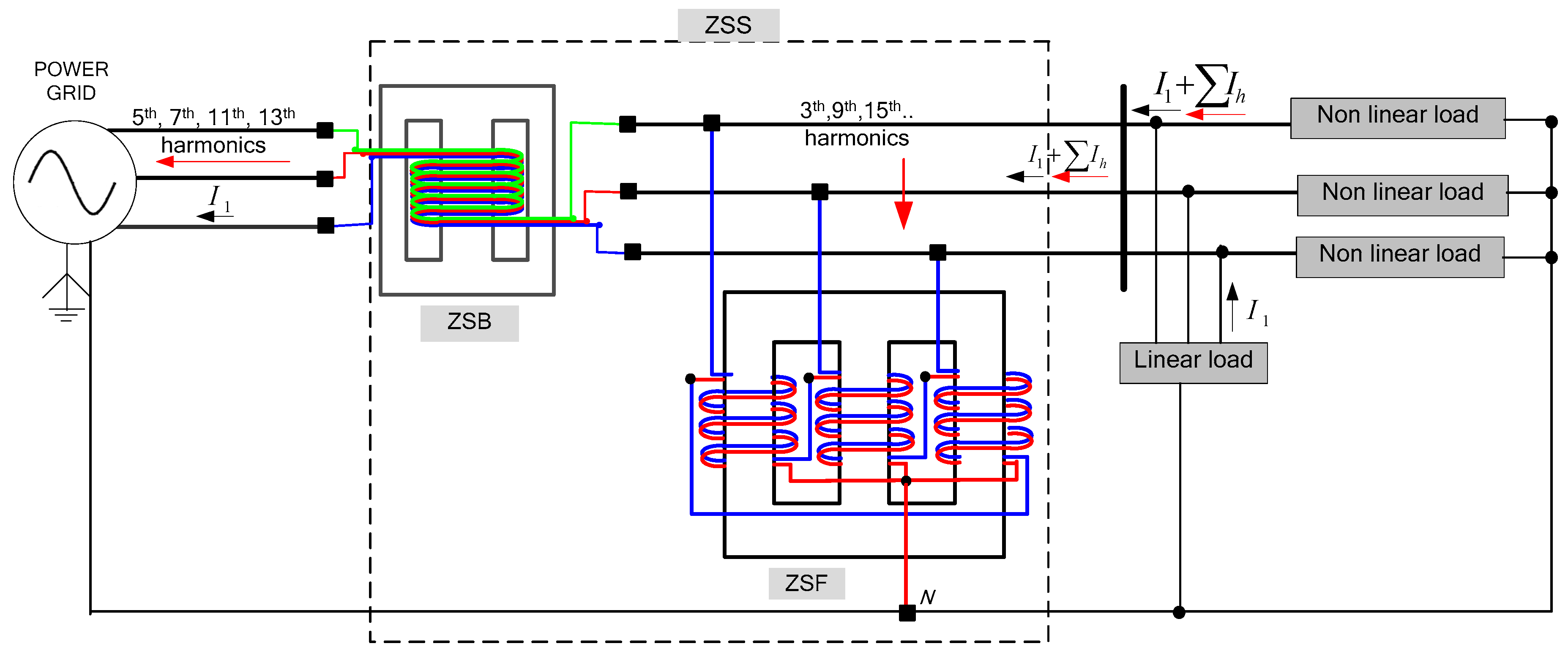
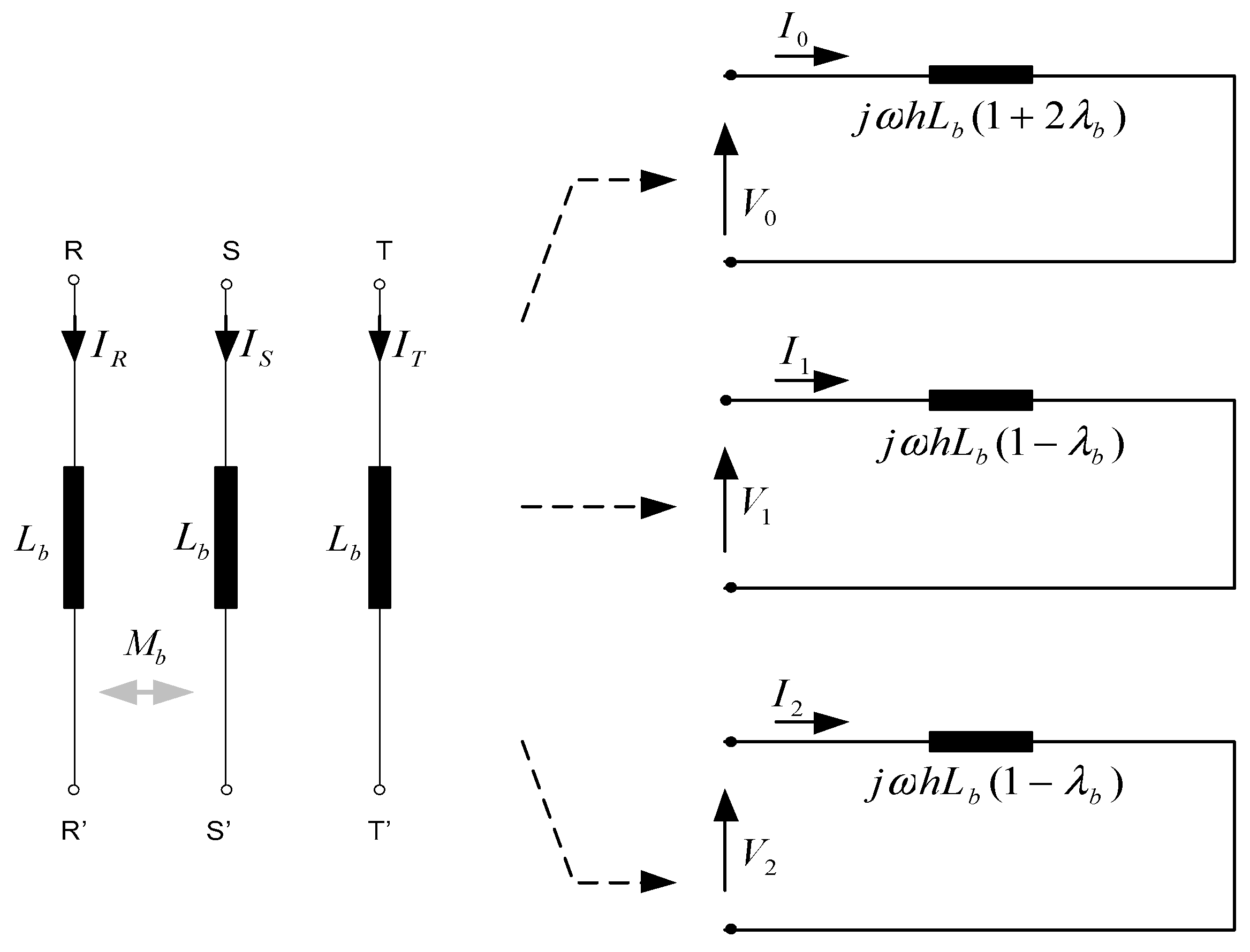
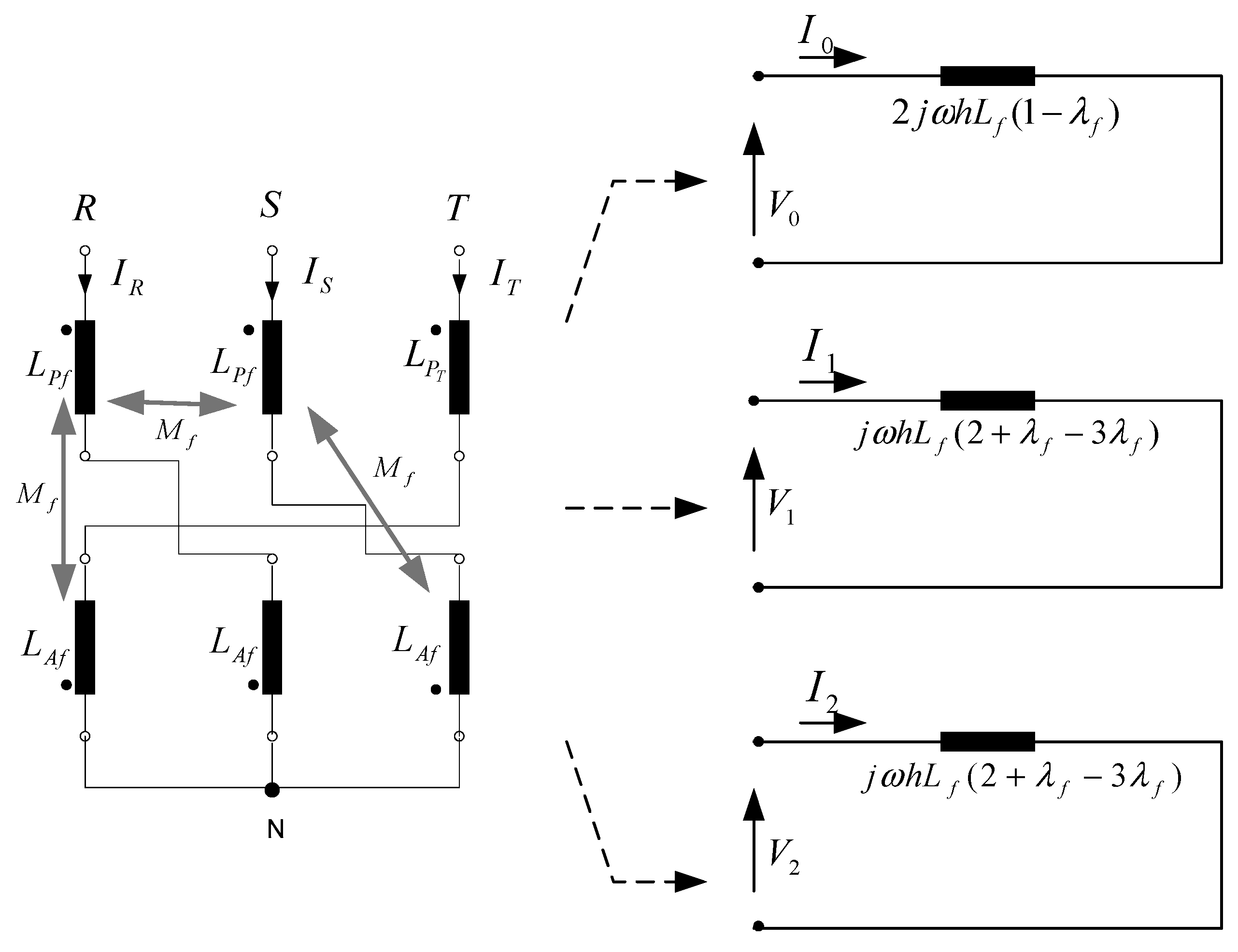
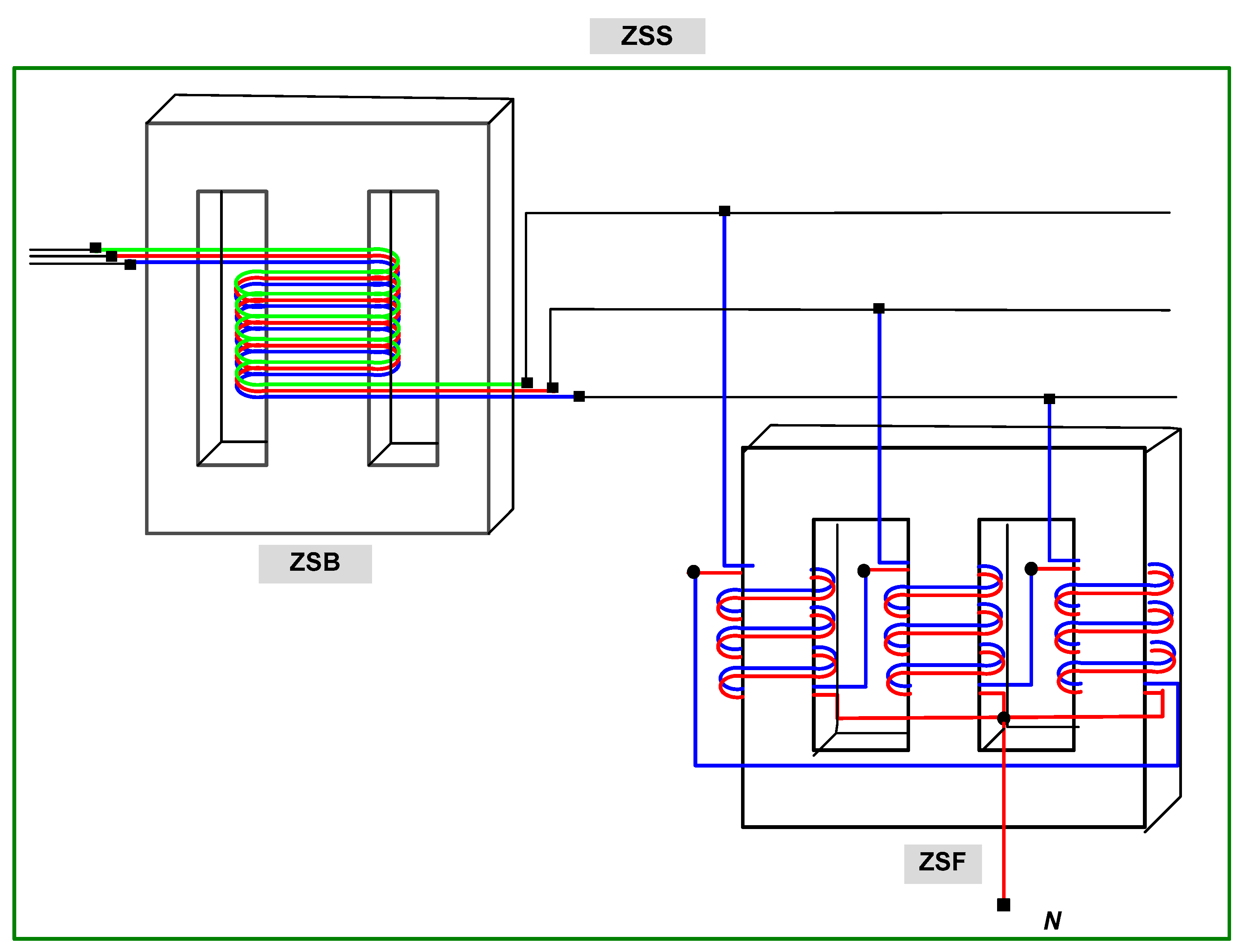
2.1. Electromagnetic Zero-Sequence Supressor (ZSS)
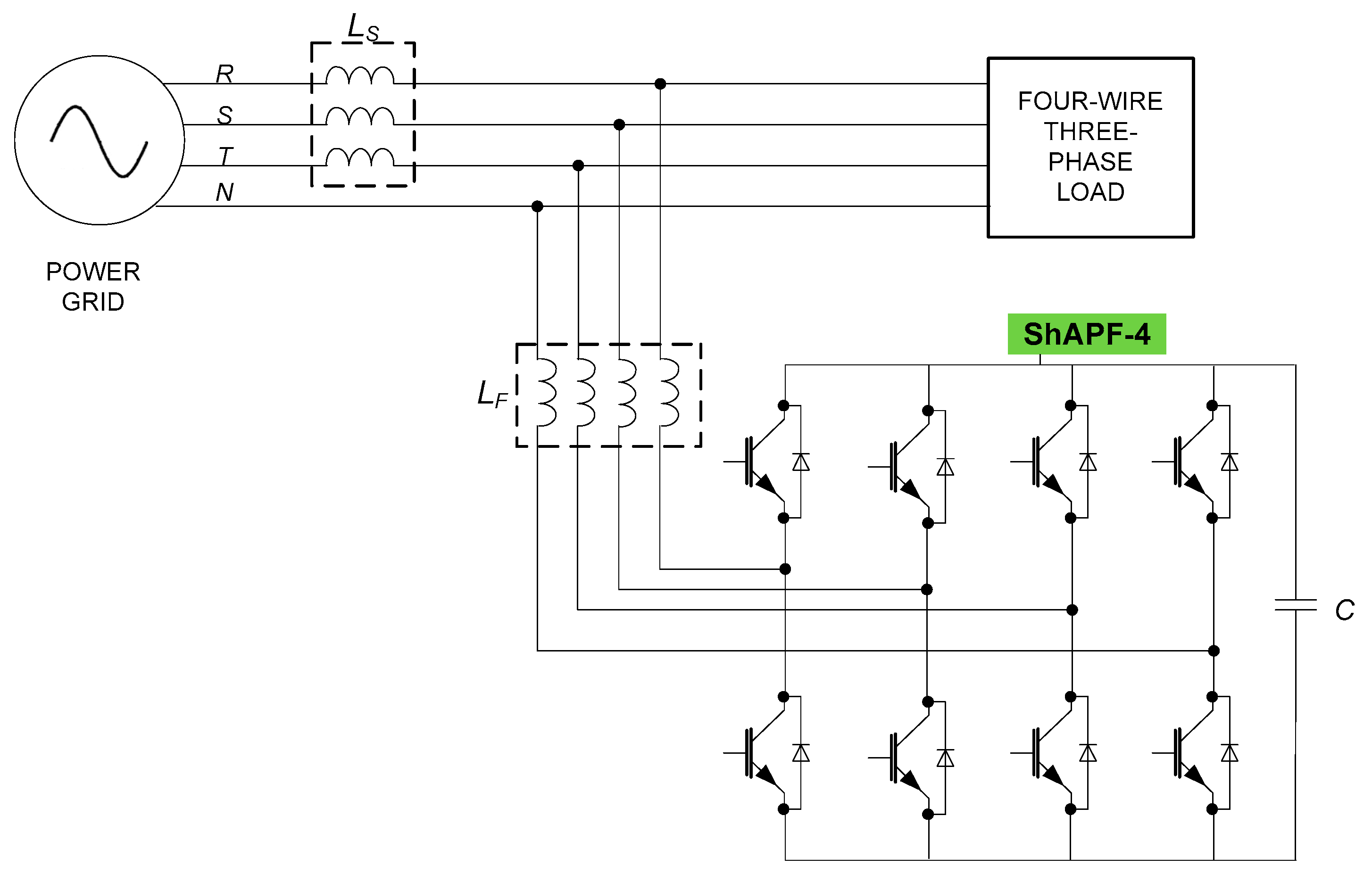
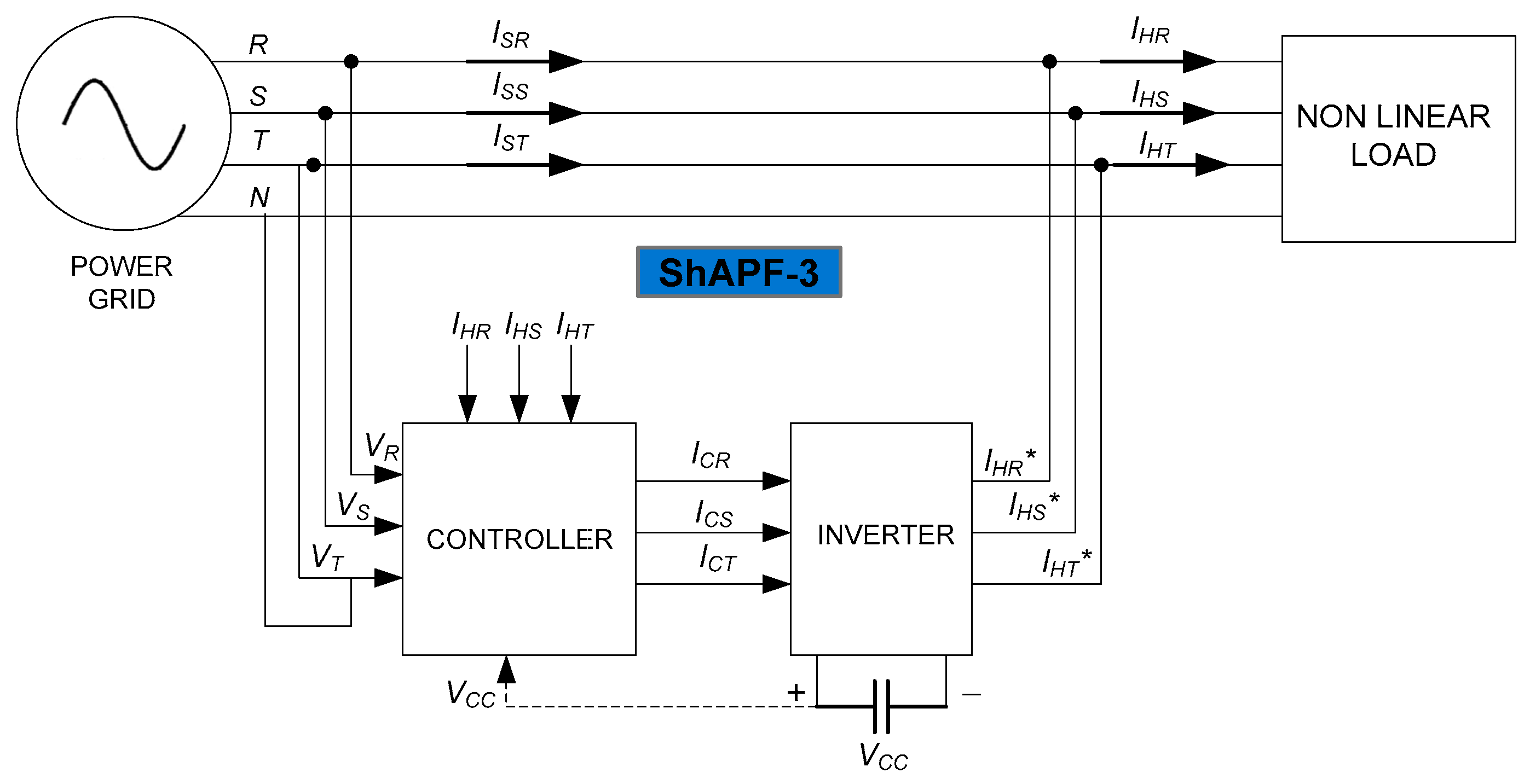
2.2. Shunt Active Power Filter
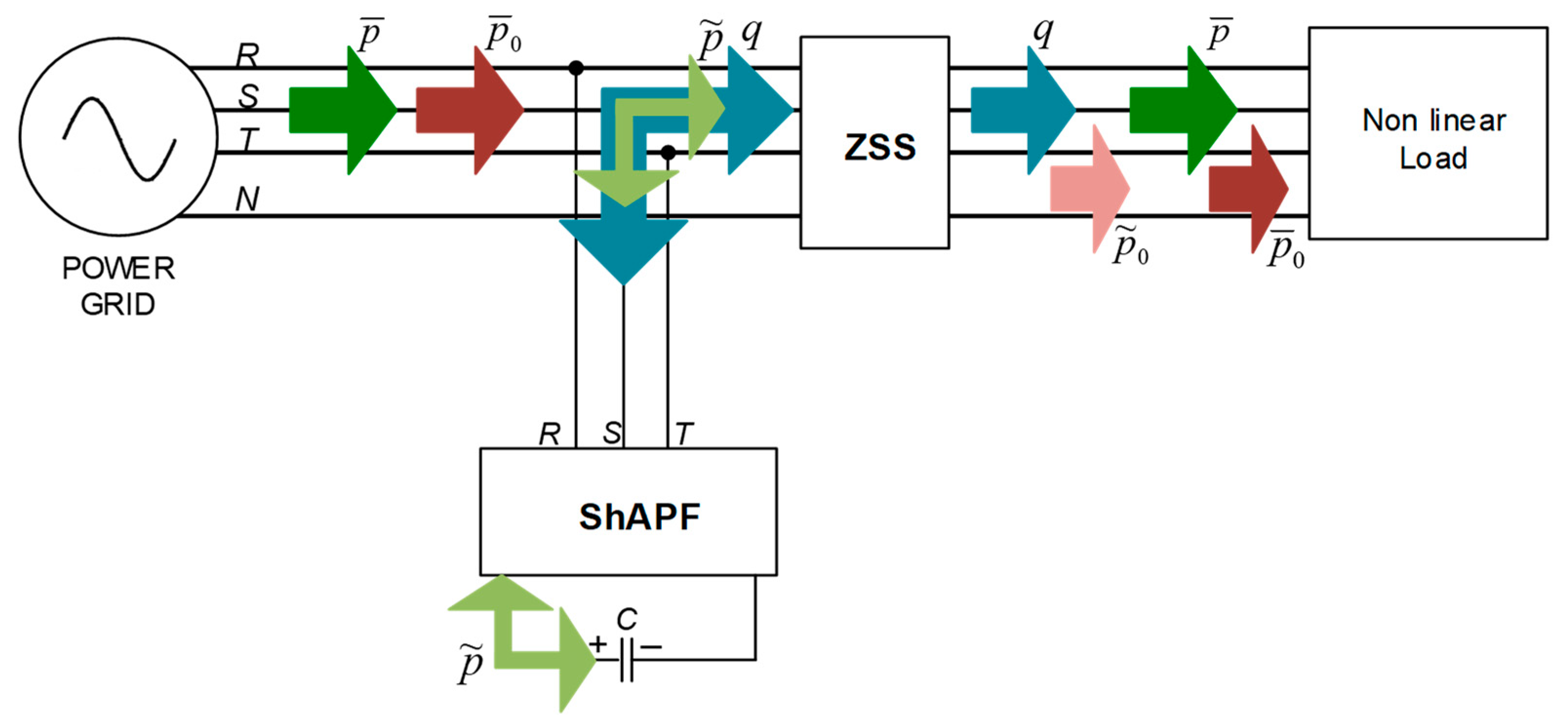
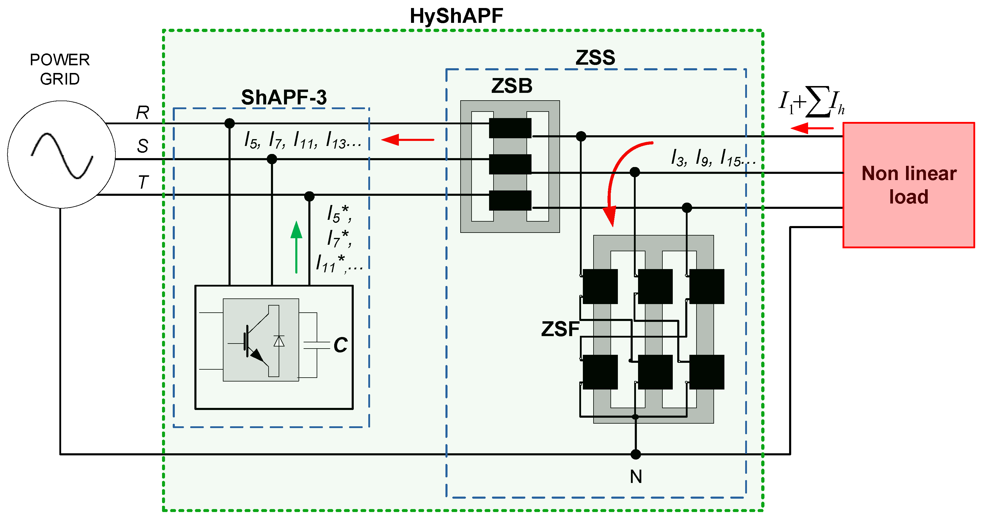
2.3. Hybrid Arrangement
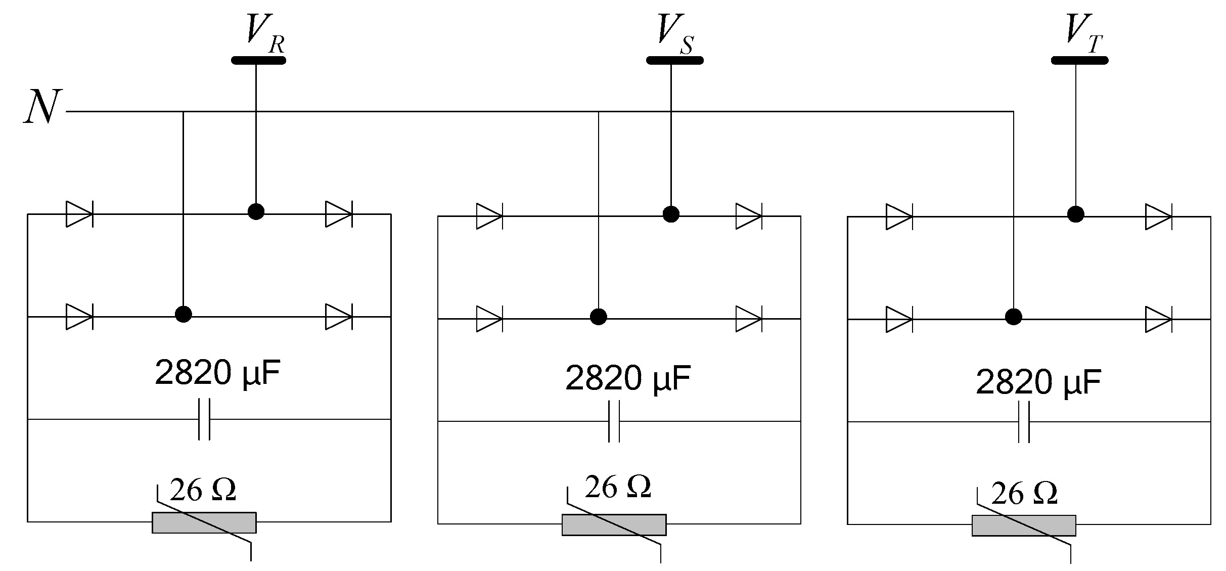
3. Simulation Results
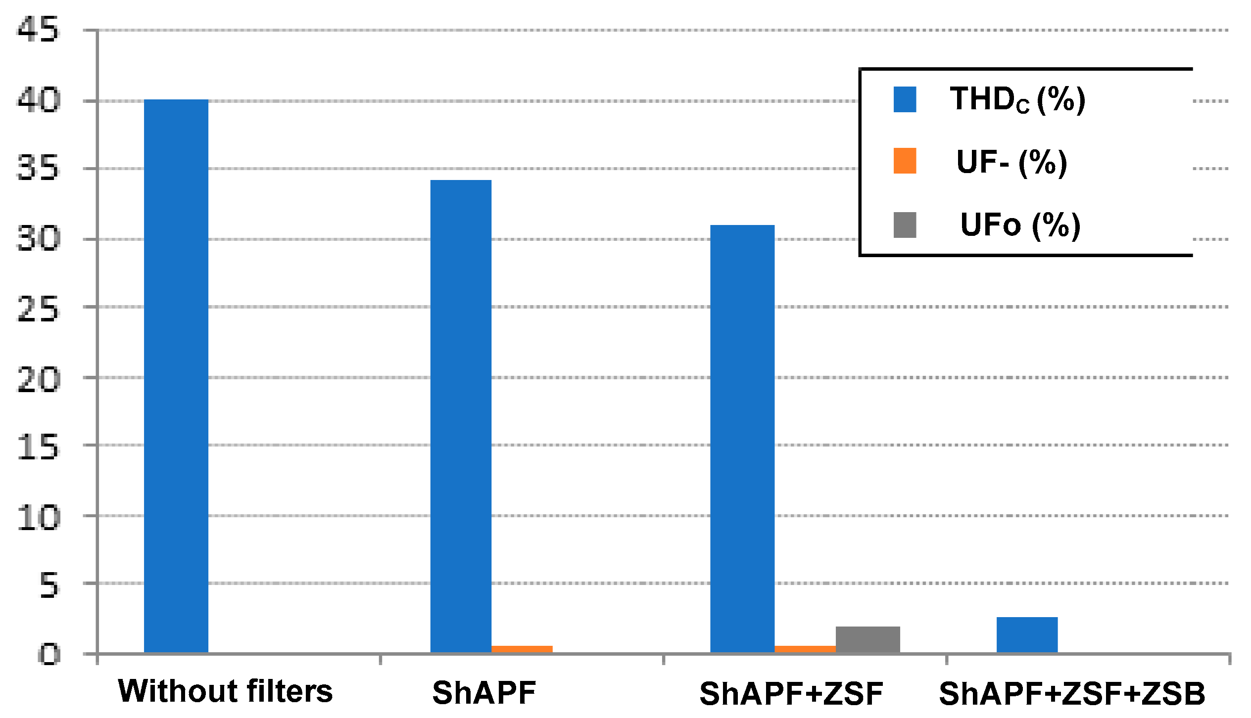
Results in Steady State
- A.
- Balanced, non-linear loads without filters
- B.
- Balanced, non-linear loads with ShAPF in operation
- C.
- Balanced, non-linear loads with ShAPF and ZSF in operation
- D.
- Balanced, non-linear loads with ShAPF and ZSS in operation
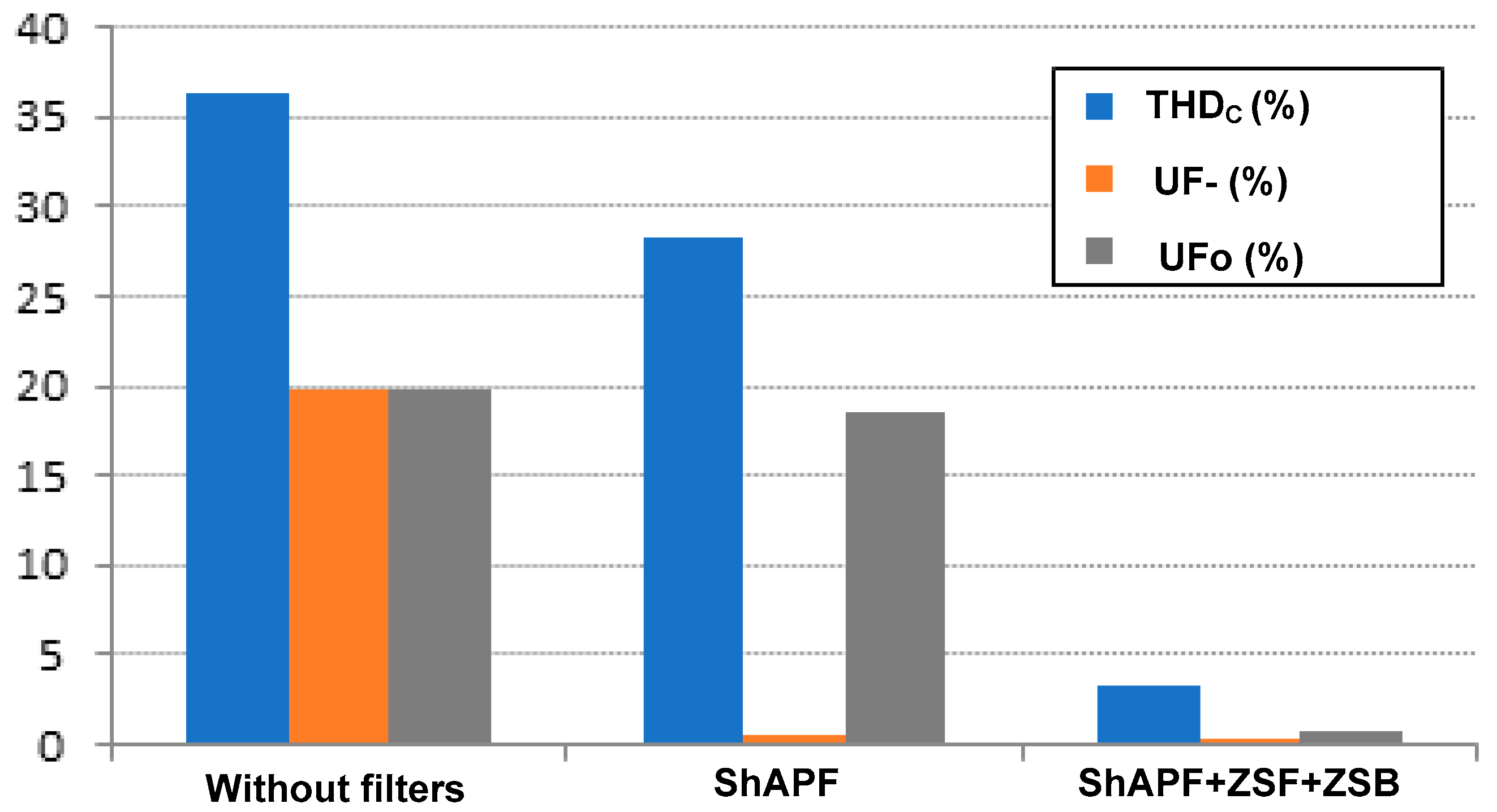
- E.
- Unbalanced, non-linear loads without the action of filters
- F.
- Unbalanced, non-linear loads only with ShAPF in operation
- G.
- Unbalanced, non-linear loads with HyShAPF in operation
- H.
- Comparing Results
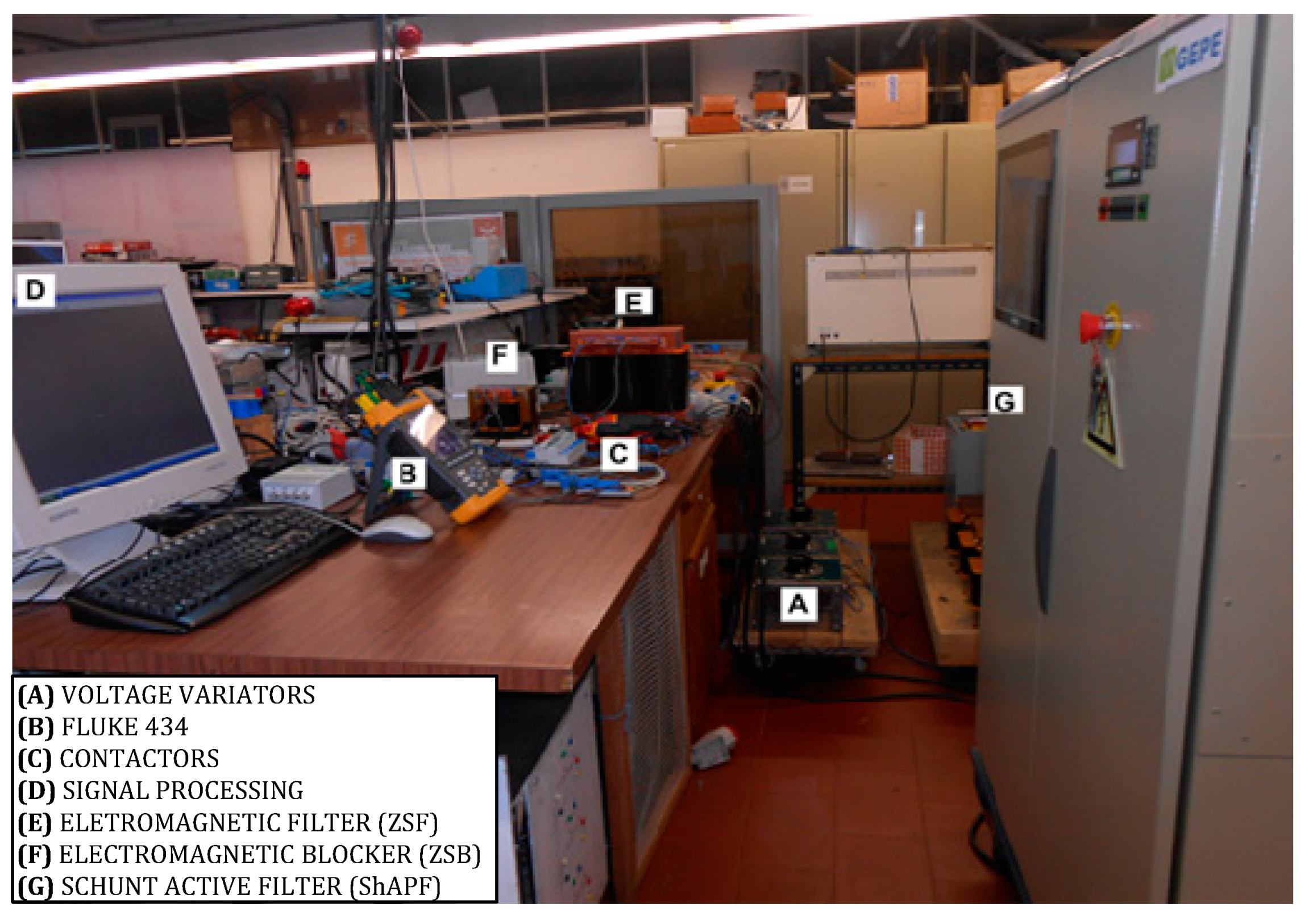
4. Experimental Results
4.1. Experimental Procedures, Materials, and Equipment
4.2. Functionalities of the Hybrid Filter Arrangement
- I.
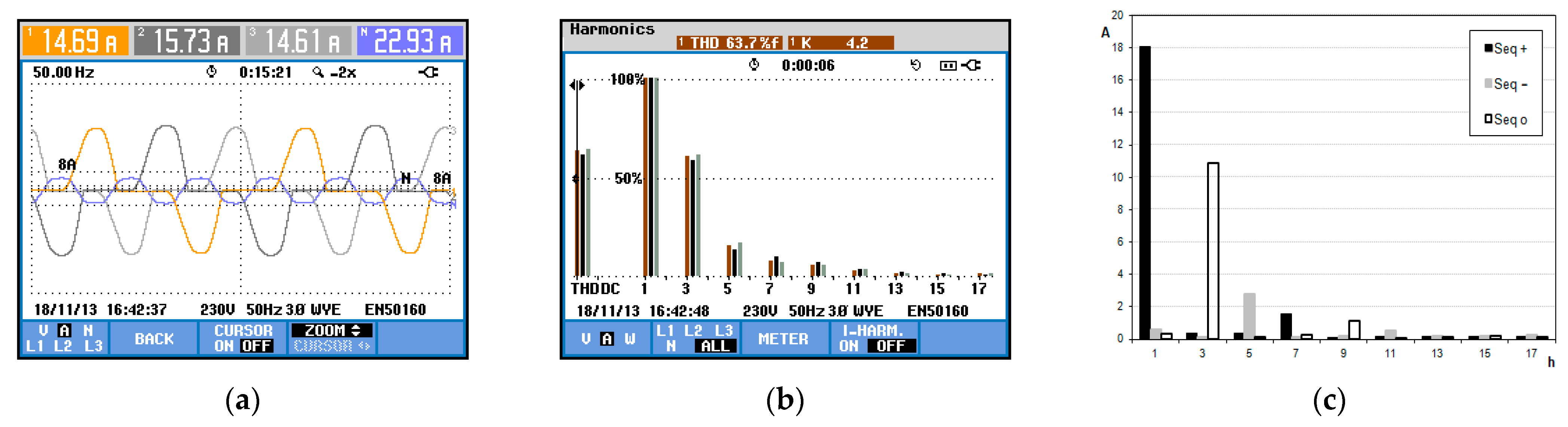
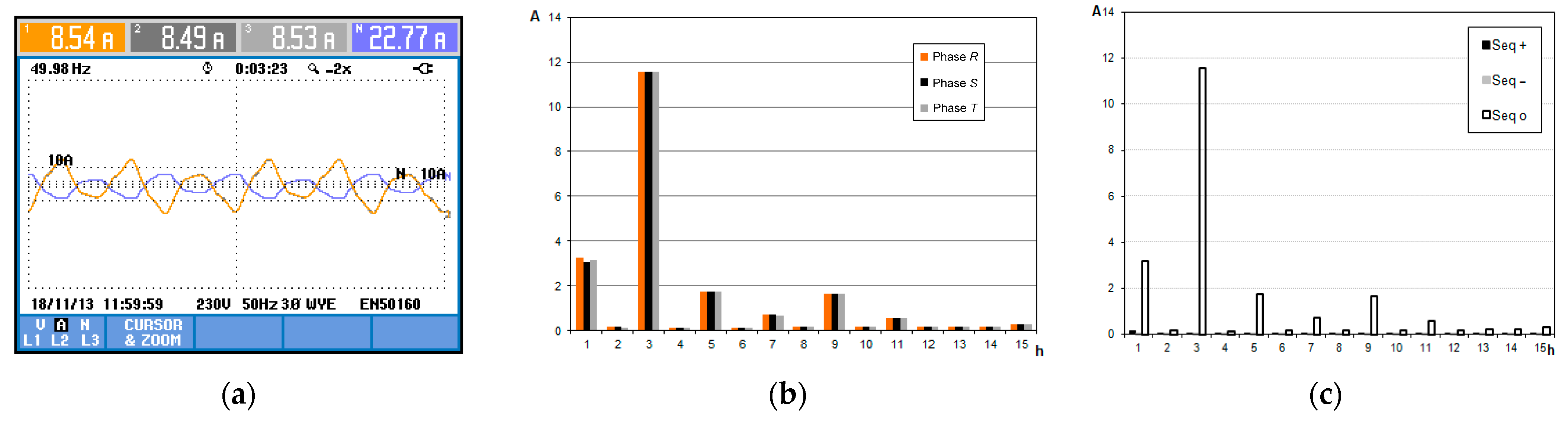
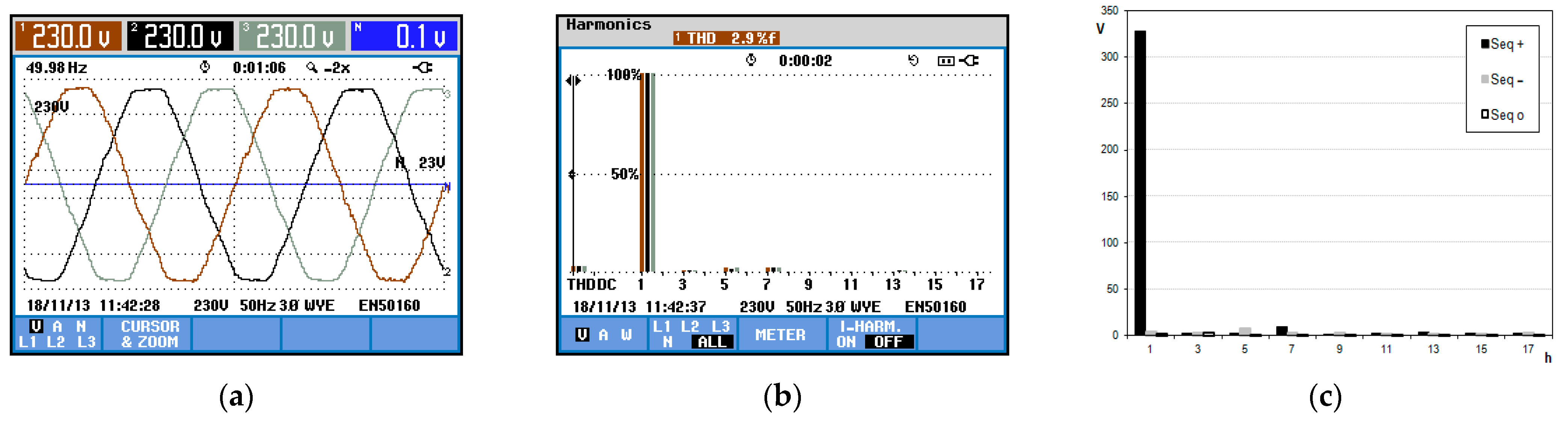
- Case 1—System without filters with balanced loads
- II.
- Case 2—ZSS and three-wire ShAPF with balanced loads
- III.
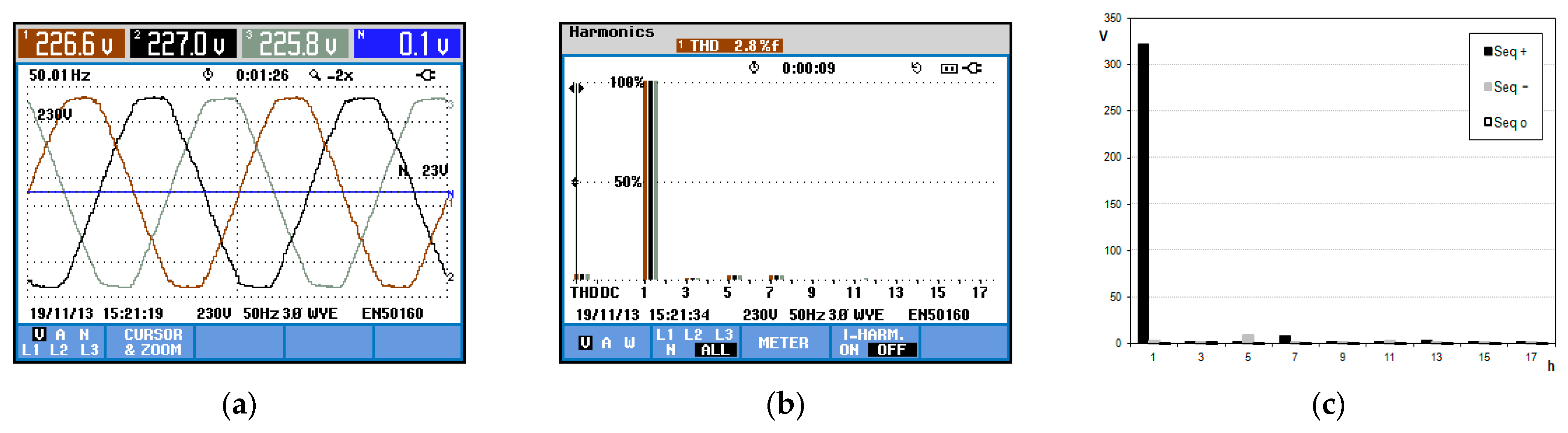
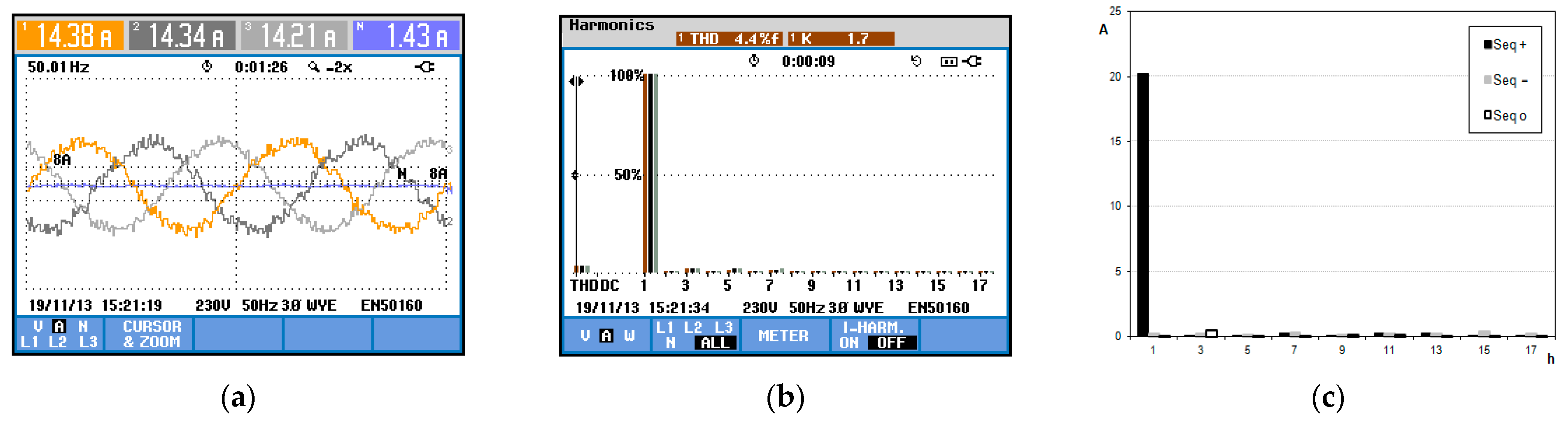
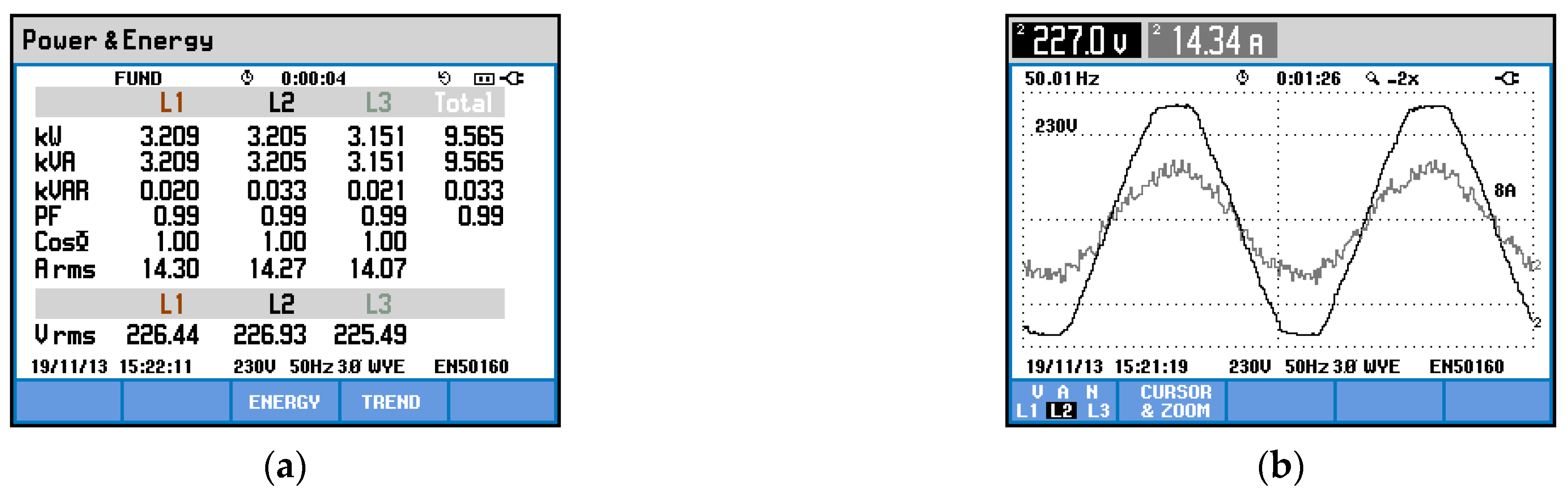
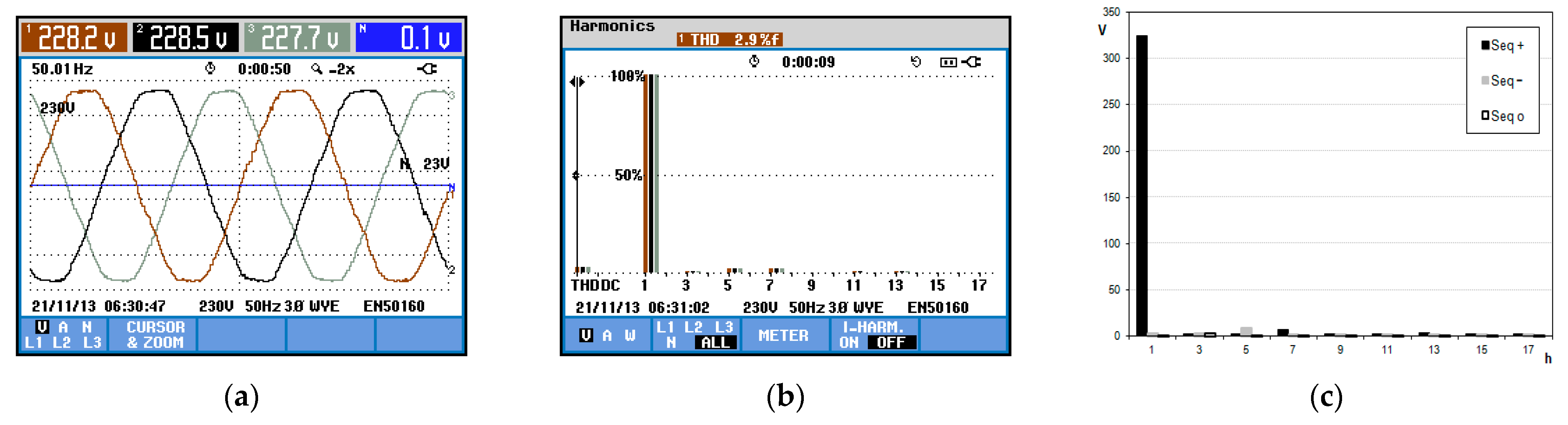
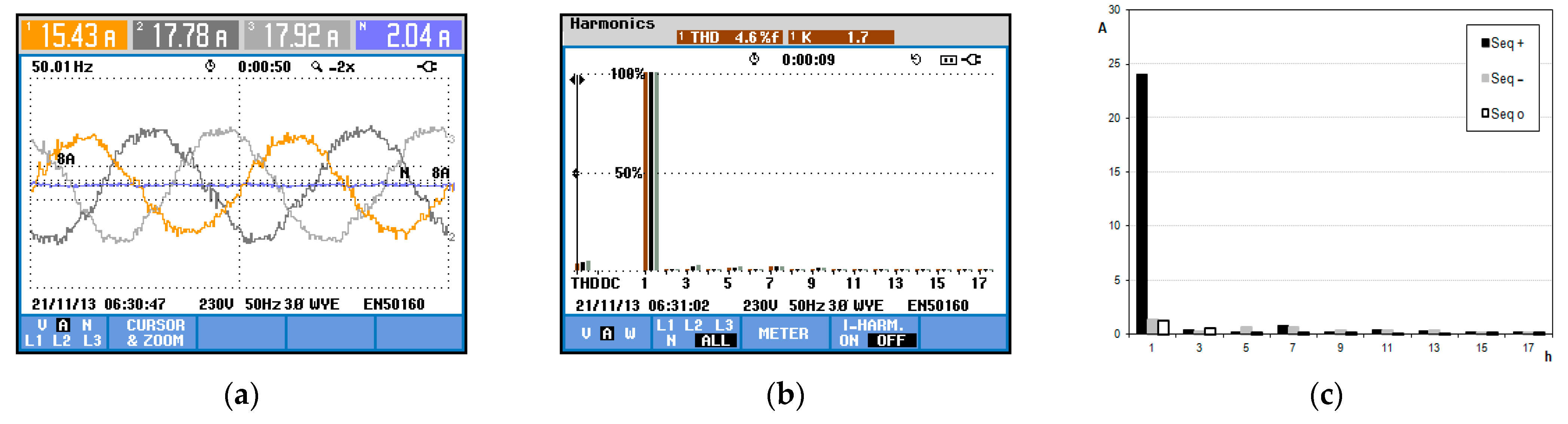
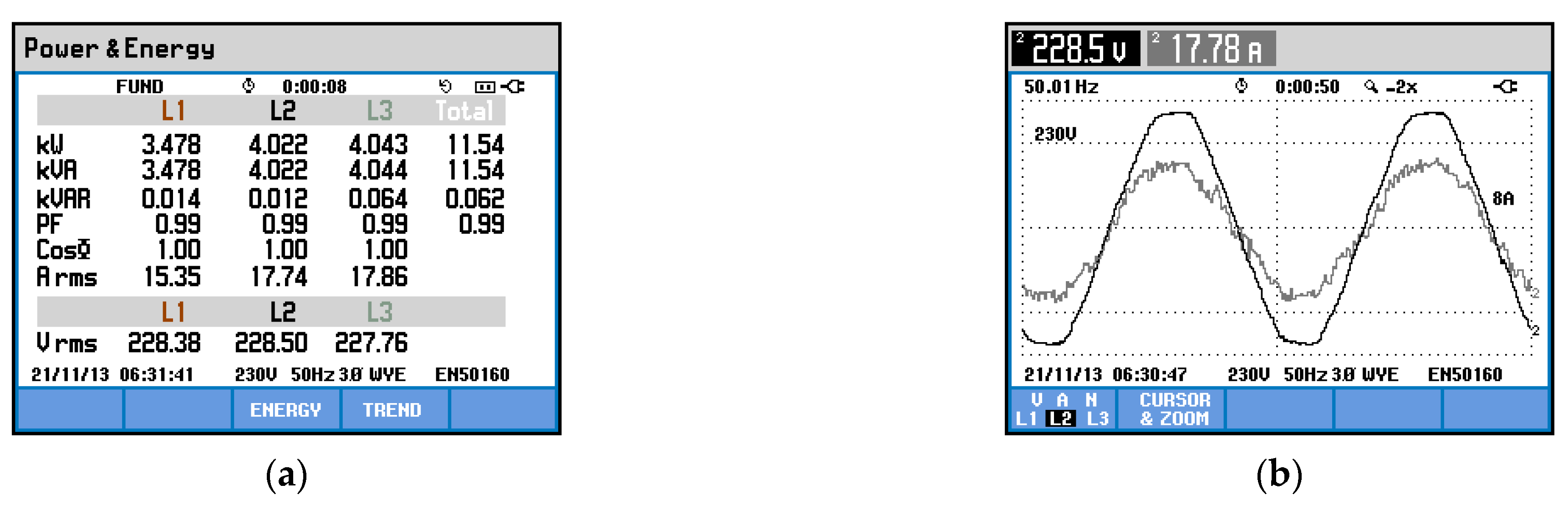
- Case 3—Four-wire ShAPF operating with balanced loads
- IV.
- Case 4—System without filters with unbalanced loads
- V.
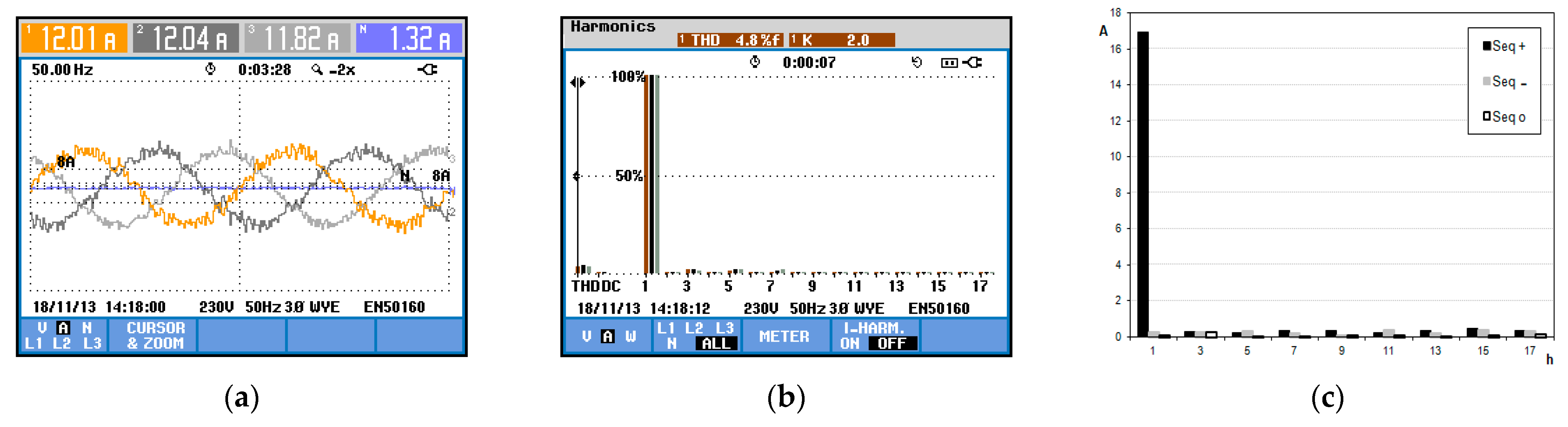
- Case 5—ZSS and three-wire ShAPF operating with unbalanced loads
- VI.
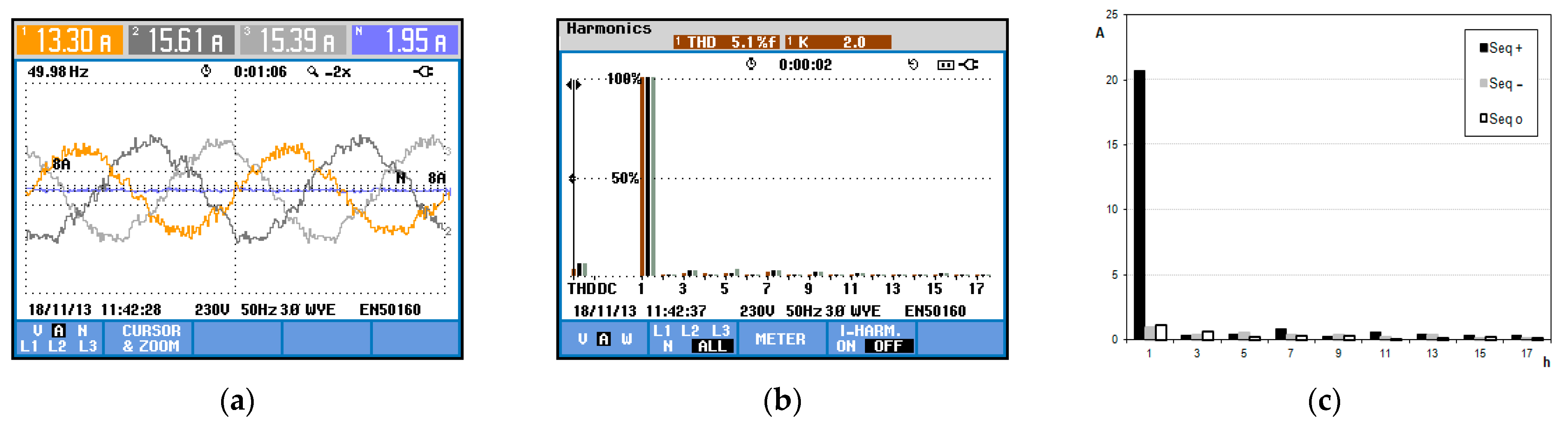
- Case 6—Four-wire ShAPF operating with unbalanced loads
5. Conclusions
Author Contributions
Funding
Data Availability Statement
Acknowledgments
Conflicts of Interest
References
- Zhang, C.; Xu, Y.; Dong, Z.Y.; Yang, L.F. Multitimescale Coordinated Adaptive Robust Operation for Industrial Multienergy Microgrids With Load Allocation. IEEE Trans. Ind. Inform. 2020, 16, 3051–3063. [Google Scholar] [CrossRef]
- Mohagheghi, S.; Raji, N. Dynamic Demand Response: A Solution for Improved Energy Efficiency for Industrial Customers. IEEE Ind. Appl. Mag. 2015, 21, 54–62. [Google Scholar] [CrossRef]
- Jiang, Z.; Hao, R.; Ai, Q.; Yu, Z.; Xiao, F. Extended multi-energy demand response scheme for industrial integrated energy system. IET Gen. Transm. Distri. 2018, 12, 3186–3192. [Google Scholar] [CrossRef]
- Liang, X. A New Composite Load Model Structure for Industrial Facilities. IEEE Trans. Ind. Appl. 2016, 52, 4601–4609. [Google Scholar] [CrossRef]
- Miranian, A.; Rouzbehi, K. Nonlinear Power System Load Identification Using Local Model Networks. IEEE Trans. Power Syst. 2013, 28, 2872–2881. [Google Scholar] [CrossRef]
- Qu, X.; Li, X.; Song, J.; He, C. An Extended Composite Load Model Taking Account of Distribution Network. IEEE Trans. Power Syst. 2018, 33, 7317–7320. [Google Scholar] [CrossRef]
- IEEE Task Force on Load Representation for Dynamic Performance, Load Representation for Dynamic Performance Analysis. IEEE Trans. Power Syst. 1993, 8, 472–482.
- Milanović, J.V.; Yamashita, K.; Villanueva, S.M.; Djokić, S.Z.; Korunović, L.M. International Industry Practice on Power System Load Modeling. IEEE Trans. Power Syst. 2013, 28, 3038–3046. [Google Scholar] [CrossRef]
- Kumar, D.; Zane, F. Harmonic Analysis of Grid Connected Power Electronic Systems in Low Voltage Distribution Networks. IEEE J. Emerg. Sel. Top. Power Electron. 2016, 4, 70–79. [Google Scholar] [CrossRef]
- Sharma, H.; Rylander, M.; Dorr, D. Grid Impacts Due to Increased Penetration of Newer Harmonic Sources. IEEE Trans. Ind. Appl. 2016, 52, 99–104. [Google Scholar] [CrossRef]
- Leite, M.C.C.; Vieira, F.A.M.; Silva, V.B.; Fortes, M.Z.; Dias, D.H.N. Harmonic Analysis of a Photovoltaic Systems Connected to Low Voltage Grid. IEEE Lat. Am. Trans. 2018, 16, 112–117. [Google Scholar] [CrossRef]
- Tang, B.; Ma, S.; Lin, S.; Chen, G.; Fu, Y. Harmonic current emission level assessment of residential loads based on impedance-gathering trend. Int. Trans. Electr. Energy Syst. 2017, 1–13. [Google Scholar] [CrossRef]
- Nassif, A.B.; Yong, J.; Xu, W.; Chung, C.Y. Indices for comparative assessment of the harmonic effect of different home appliances. Int. Trans. Electr. Energy Syst. 2013, 23, 638–654. [Google Scholar] [CrossRef]
- Das, J.C. Harmonic Generation Effects Propagation and Control, 1st ed.; CRC Press: New York, NY, USA, 2017; ISBN 9781498745468. [Google Scholar]
- IEEE TASK FORCE. Effect of harmonics on equipments. IEEE Trans. Power Deliv. Piscataway 1993, 8, 672–680. [Google Scholar] [CrossRef]
- EUROPEAN STANDARD. EN 50160: Voltage Characteristics of Electricity Supplied by Public Distribution Systems; Wroclaw University of Technology: Wroclaw, Poland, 1994; 16p. [Google Scholar]
- IEEE SA 519-1992; Recommended Practices and Requirements for Harmonic Control in Electrical Power Systems. [S. l.: S.n]; IEEE: New York, NY, USA, 1992; 100p, (Industrial Power Converters Committee). Available online: https://edisciplinas.usp.br/pluginfile.php/1589263/mod_resource/content/1/IEE%20Std%20519-2014.pdf (accessed on 22 January 2023).
- Pichan, M.; Karimi, M.; Simorgh, H. Improved low-cost sliding mode control of 4-leg inverter for isolated microgrid applications. Int Trans Electr Energ Syst. 2018, 28, e2642. [Google Scholar] [CrossRef]
- Nibouche, M.; Bouchhida, O.; Makhlouf, B. Design, analysis and implementation of real-time harmonics elimination: A generalized approach. IET Power Electron. 2014, 7, 2424–2436. [Google Scholar]
- Freitas, S.C.L.; Oliveira, L.C.O.; Silva Oliveira, P.; Exposto, B.; Oliveira Pinto, J.G.; Afonso, J.L. Modeling, design, and experimental test of a zero-sequence current electromagnetic suppressor. Int. Trans. Electr. Energy Syst. 2020, 30. [Google Scholar] [CrossRef]
- Sousa, T.J.C.; Monteiro, V.; Afonso, J.A. Selective Harmonic Measurement and Compensation Using Smart Inverters in a Microgrid with Distributed Generation. In Proceedings of the 2018 IEEE 16th International Conference on Industrial Informatics (INDIN), Porto, Portugal, 18–20 July 2018; pp. 439–444. [Google Scholar] [CrossRef]
- Monteiro, L.F.C.; Aredes, M.; Couto, C.; Afonso, J.L. Control algorithms for a unified power quality conditioner based on three-level converters. Int. Trans. Electr. Energy Syst. 2014, 25, 2394–2411. [Google Scholar] [CrossRef]
- Jou, B.H.L.; Wu, J.C.; Wu, K.D.; Chiang, W.J.; Chen, Y.H. Analysis of Zig-Zag Transformer Applying in the Three-Phase Four-Wire Distribution Power System. IEEE Trans. Power Deliv. 2005, 20, 1168–1173. [Google Scholar] [CrossRef]
- Schoene, J.; Walling, R.; Bo, Y.; Niemann, B.; Zheglov, V.; Guinn, D.; Peele, S.; Grappe, J.; Zavadil, B.; Freeman, L. Analysis and mitigation of excessive zero-sequence harmonic currents in distribution systems. In Proceedings of the Transmission and Distribution Conference and Exposition (T&D) IEEE PES, Orlando, FL, USA, 7–10 May 2012; pp. 1–6. [Google Scholar] [CrossRef]
- Rahmani, S.; Hamadi, A.; Al-Haddad, K.; Dessaint, L.A. A Combination of Shunt Hybrid Power Filter and Thyristor-Controlled Reactor for Power Quality. IEEE Trans. Ind. Electron. 2014, 61, 2152–2164. [Google Scholar] [CrossRef]
- Bosch, S.; Staiger, J.; Steinhart, H. Predictive Current Control for an Active Power Filter With LCL-Filter. IEEE Trans. Ind. Electron. 2018, 65, 4943–4952. [Google Scholar] [CrossRef]
- Oliveira, J.C.; Oliveira, L.C.O.; Belchior, F.N.; Oliveira, R.N.; Barbosa, J.A., Jr. Frequency domain model for zero-sequence electromagnetic harmonic filter performance analysis. Int. Trans. Electr. Energy Syst. 2014, 1–15. [Google Scholar] [CrossRef]
- Oliveira, L.C.O.; Oliveira, R.N.; Souza, J.B.; Freitas, S.C.L. Electromagnetic Zero-Sequence Harmonics Blocker: Modeling and Experimental Analysis. J. Energy Power Eng. 2014, 8, 1425–1431. [Google Scholar]
- Maher, M.; Abdel Aleem, S.H.E.; Ibrahim, A.M.; El-Shahat, A. Novel Mathematical Design of Triple-Tuned Filters for Harmonics Distortion Mitigation. Energies 2023, 16, 39. [Google Scholar] [CrossRef]
- Sufyan, A.; Jamil, M.; Ghafoor, S.; Awais, Q.; Ahmad, H.A.; Khan, A.A.; Abouobaida, H. A Robust Nonlinear Sliding Mode Controller for a Three-Phase Grid-Connected Inverter with an LCL Filter. Energies 2022, 15, 9428. [Google Scholar] [CrossRef]
- Zhou, H.; Liu, J.; Fang, Z.; Zhang, P.; Zhang, B.; Ma, M.; Zeng, J. Control Strategy for Resonant Inverter in High Frequency AC Power Distribution System with Harmonic Suppression and Transient Performance Improvement. Energies 2022, 15, 8992. [Google Scholar] [CrossRef]
- Sahoo, B.; Alhaider, M.M.; Rout, P.K. Effective Harmonic Cancellation Technique for a Three-Phase Four-Wire System. Energies 2022, 15, 7526. [Google Scholar] [CrossRef]
- Park, J.-I.; Park, C.-H. Harmonic Contribution Assessment Based on the Random Sample Consensus and Recursive Least Square Methods. Energies 2022, 15, 6448. [Google Scholar] [CrossRef]
- Afonso, J.L.; Silva, H.J.R.; Martins, J.S. Active Filters for Power Quality Improvement; IEEE Porto Powertech: Porto, Portugal, 2001; pp. 1–8. [Google Scholar]
- Afonso, J.L.; Aredes, M.; Watanabe, E.H.; Martins, J.S. Shunt Active Filter for Power Quality Improvement; International Conference User Interface Engineering: Lisboa, Portugal, 2000; pp. 683–691. [Google Scholar]
- Mannen, T.; Fukasawa, I.; Fujita, H. A New Control Method of Suppressing DC Capacitor Voltage Ripples Caused by Third-Order Harmonic Compensation in Three-Phase Active Power Filters. IEEE Trans. Ind. Appl. 2018, 54, 6149–6158. [Google Scholar] [CrossRef]
- Akagi, H.; Kanazawa, Y.; Nabae, A. Generalized Theory of the Instantaneous Reactive Power in Three-PhaseCircuits, In Proceedings of the IPEC’83—Int. Power Electronics Conf. Tokyo, Japan; 1983; pp. 1375–1386. [Google Scholar]
- Akagi, H.; Kanazawa, Y.; Nabae, A. Instanataneous Reactive Power Compensator Comprising Switching Devices without Energy Storage Compenents. IEEE Trans. Industry Applic. 1984, 3, 625–630. [Google Scholar] [CrossRef]
- Afonso, J.L.; Couto, C.; Martins, J. Active Filters with Control Based on the p-q Theory; IEEE Industrial Electronics Society Newsletter: New York, NY, USA, 2000; pp. 5–10. ISSN 0746-1240. Available online: https://core.ac.uk/download/pdf/55603571.pdf (accessed on 22 January 2023).
- Afonso, J.L.; Freitas, M.J.S.; Martins, J.S. p-q Theory Power Components Calculations; ISIE’2003—IEEE International Symposium on Industrial Electronics: Rio de Janeiro, Brasil, 2003; ISBN 0-7803-7912-8. [Google Scholar]
- McLymann, C.W.T. Transformer and Inductor Design Handbook, 3rd ed.; CRC Press: New York, NY, USA, 2004; ISBN 0824753933. [Google Scholar]
- Pregitzer, R.; Costa, J.C.; Martins, J.S.; Afonso, J.L. Simulation and implementation of a 3-phase 4-wire shunt active power filter. In Proceedings of the 6th International Conference on Harmonics and Power Quality, Cascais, Portugal, 1–5 October 2006; pp. 1–6. [Google Scholar]


| Parameter | Value |
|---|---|
| Power grid voltages | ≈230 V |
| Frequency | 50 Hz |
| Electromagnetic filter (ZSF) | Lf = 300 mH; Rf = 0.2 Ω; λf = 0.998 |
| Electromagnetic blocker (ZSB) | Lb = 5 mH; Rb = 0.03 Ω; λb = 0.998 |
| Single-phase rectifiers with capacitive filter | R = 42 Ω; C = 500 uF |
| Three-phase rectifier with inductive filter | R = 42 Ω; L = 5 mH |
| ShAPF DC voltage | 750 V |
| Arrangements | Currents (A_rms) | Sequencies (rms) | THDC (%) | UF (%) | |||||||
|---|---|---|---|---|---|---|---|---|---|---|---|
| R | S | T | (+) | (-) | (0) | R | S | T | (+) | (0) | |
| BL/without filters | 21.2 | 21.1 | 21.2 | 19.7 | 3.1 | 7.1 | 39.9 | 40 | 40 | 0.1 | 0.1 |
| BL/ShAPF | 21.9 | 21.9 | 22.0 | 20.1 | 0.5 | 7.1 | 34.4 | 34.6 | 33.6 | 0.5 | 0.0 |
| BL/ShAPF + ZSF | 21.6 | 22 | 21.6 | 20.8 | 0.4 | 6.4 | 31.7 | 30.4 | 31.0 | 0.6 | 1.9 |
| BL/ShAPF + ZSF + ZSB | 20.6 | 20.6 | 20.6 | 20.6 | 0.4 | 0.1 | 2.7 | 2.7 | 2.7 | 0.1 | 0.1 |
| UL/without filters | 10.4 | 21.1 | 21.1 | 16.7 | 4.7 | 5.8 | 28.8 | 39.9 | 40.0 | 19.7 | 19.8 |
| UL/ShAPF | 15.0 | 19.4 | 20.4 | 17.5 | 0.5 | 5.8 | 33.8 | 26.1 | 25.1 | 0.5 | 18.6 |
| UL/ShAPF + ZSF + ZSB | 17.4 | 17.3 | 17.5 | 17.4 | 0.4 | 0.2 | 3.0 | 3.7 | 3.1 | 0.1 | 0.7 |
| Parameter | Value |
|---|---|
| ZSF nominal power | 6.7 kVA |
| ZSF nominal voltage | 230 V |
| ZSF coil self-inductance | 300 mH |
| ZSF mutual inductance between coils in the same column | 0.99 |
| ZSB nominal power | 1.1 kVA |
| ZSB maximum voltage drop | 15 V |
| ZSB coil self-inductance | 5 mH |
| ZSB mutual inductance between coils in the same column | 0.99 |
| Parameter | Value |
|---|---|
| Sampling frequency | 32 kHz |
| DC-link capacitor | 740 uF |
| Output inductors | 5 mH |
| Maximum switching frequency | 16 kHz |
| Case | Loads | ZSS | ShAPF-3 | ShAPF-4 |
|---|---|---|---|---|
| 1 | Balanced | OFF | OFF | OFF |
| 2 | Balanced | ON | ON | OFF |
| 3 | Balanced | OFF | OFF | ON |
| 4 | Unbalanced | OFF | OFF | OFF |
| 5 | Unbalanced | ON | ON | OFF |
| 6 | Unbalanced | OFF | OFF | ON |
| Case 1: Without Filters | Case 2: With ZSS and ShAPF-3 | Case 3: With ShAPF-4 | |
|---|---|---|---|
| Voltages THD (%) | 4.2 | 3.0 | 2.9 |
| Current THD (%) | 63.1 | 3.6 | 4.2 |
| Neutral Current (A) | 22.93 | 1.43 | 2.04 |
| PF | 0.8 | 0.99 | 0.99 |
| Case 4: Without Filters | Case 5: With ZSS and ShAPF-3 | Case 6: With ShAPF-4 | |
|---|---|---|---|
| Voltages THD (%) | 4.1 | 2.9 | 3.0 |
| Current THD (%) | 66.3 | 3.7 | 5.4 |
| Neutral Current (A) | 20.27 | 1.32 | 1.95 |
| PF | 0.8 | 0.98 | 1 |
Disclaimer/Publisher’s Note: The statements, opinions and data contained in all publications are solely those of the individual author(s) and contributor(s) and not of MDPI and/or the editor(s). MDPI and/or the editor(s) disclaim responsibility for any injury to people or property resulting from any ideas, methods, instructions or products referred to in the content. |
© 2023 by the authors. Licensee MDPI, Basel, Switzerland. This article is an open access article distributed under the terms and conditions of the Creative Commons Attribution (CC BY) license (https://creativecommons.org/licenses/by/4.0/).
Share and Cite
Freitas, S.; Oliveira, L.C.; Oliveira, P.; Exposto, B.; Pinto, J.G.; Afonso, J.L. New Topology of a Hybrid, Three-Phase, Four-Wire Shunt Active Power Filter. Energies 2023, 16, 1384. https://doi.org/10.3390/en16031384
Freitas S, Oliveira LC, Oliveira P, Exposto B, Pinto JG, Afonso JL. New Topology of a Hybrid, Three-Phase, Four-Wire Shunt Active Power Filter. Energies. 2023; 16(3):1384. https://doi.org/10.3390/en16031384
Chicago/Turabian StyleFreitas, Stefani, Luis Carlos Oliveira, Priscila Oliveira, Bruno Exposto, José Gabriel Pinto, and Joao L. Afonso. 2023. "New Topology of a Hybrid, Three-Phase, Four-Wire Shunt Active Power Filter" Energies 16, no. 3: 1384. https://doi.org/10.3390/en16031384
APA StyleFreitas, S., Oliveira, L. C., Oliveira, P., Exposto, B., Pinto, J. G., & Afonso, J. L. (2023). New Topology of a Hybrid, Three-Phase, Four-Wire Shunt Active Power Filter. Energies, 16(3), 1384. https://doi.org/10.3390/en16031384