Heat Transfer Analysis and Operation Optimization of an Intermediate Fluid Vaporizer
Abstract
1. Introduction
2. Basic Theories
2.1. Calculation Method of Heat Transfer Characteristics
2.1.1. Propane Vaporizer
2.1.2. LNG Vaporizer
2.1.3. NG Heater
2.1.4. Heat Transfer Coefficient of Each Segment
2.2. Mathematical Model of IFV Operation Optimization Configuration
2.2.1. Model Assumptions
- The seawater temperature will not affect the energy consumption of the seawater pumps;
- The seawater pumps supply seawater to IFVs with fixed energy consumption per unit mass flow of seawater;
- Each IFV performs consistently and operates in ideal conditions;
- The quality of seawater remains unchanged and the physical parameters are the same as those of pure water;
- The flow of seawater and LNG into the IFV can be controlled continuously.
2.2.2. Objective Function
- G—total seawater flow rate of the regasification system, t/h;
- a—total number of IFVs;
- xi—operating status of the ith IFV, where 1 means on and 0 means off;
- t—seawater inlet temperature of the IFVs, °C;
- qi—LNG flow rate of the ith IFV, t/h;
- H(t, qi)—seawater flow required for the ith IFV to operate at the seawater inlet temperature t, °C, and LNG flow qi, t/h.
2.2.3. Restrictions
- (1)
- IFV operation flow constraints
- (2)
- Constraints on the output volume of the regasification system
3. Case Study
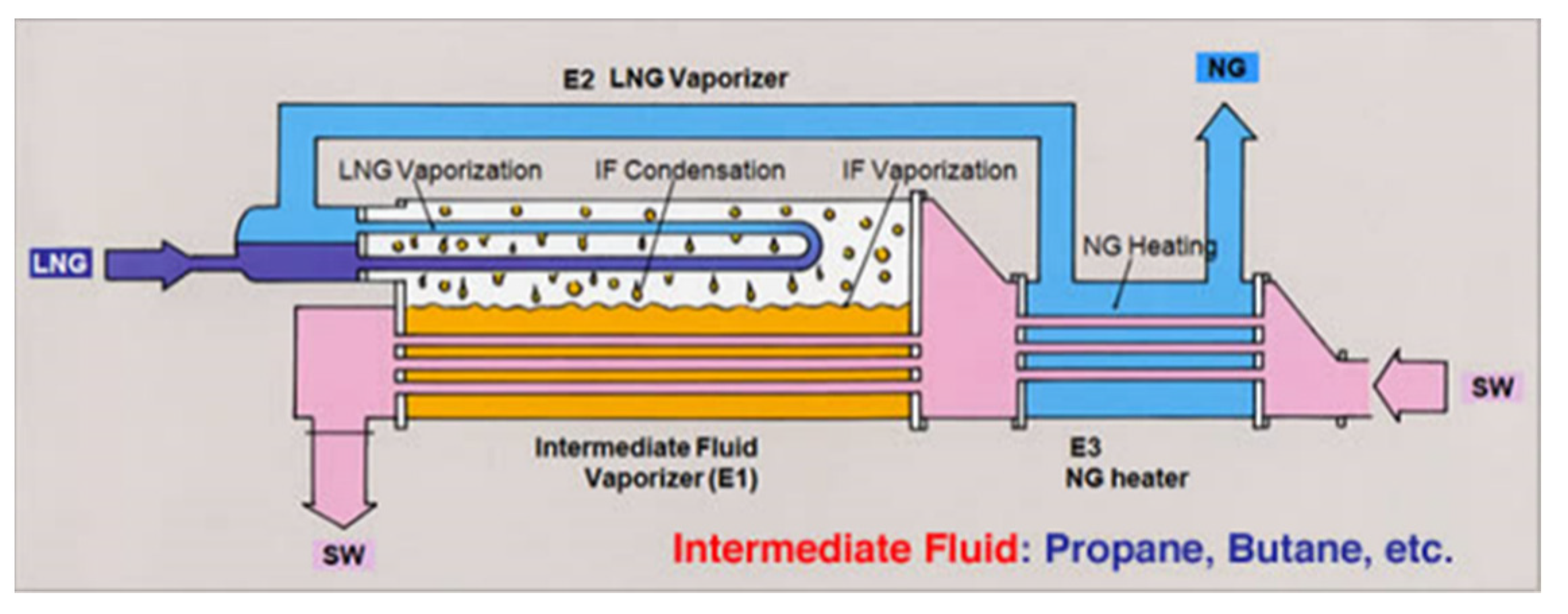
3.1. Project Overview
3.2. Numerical Simulation
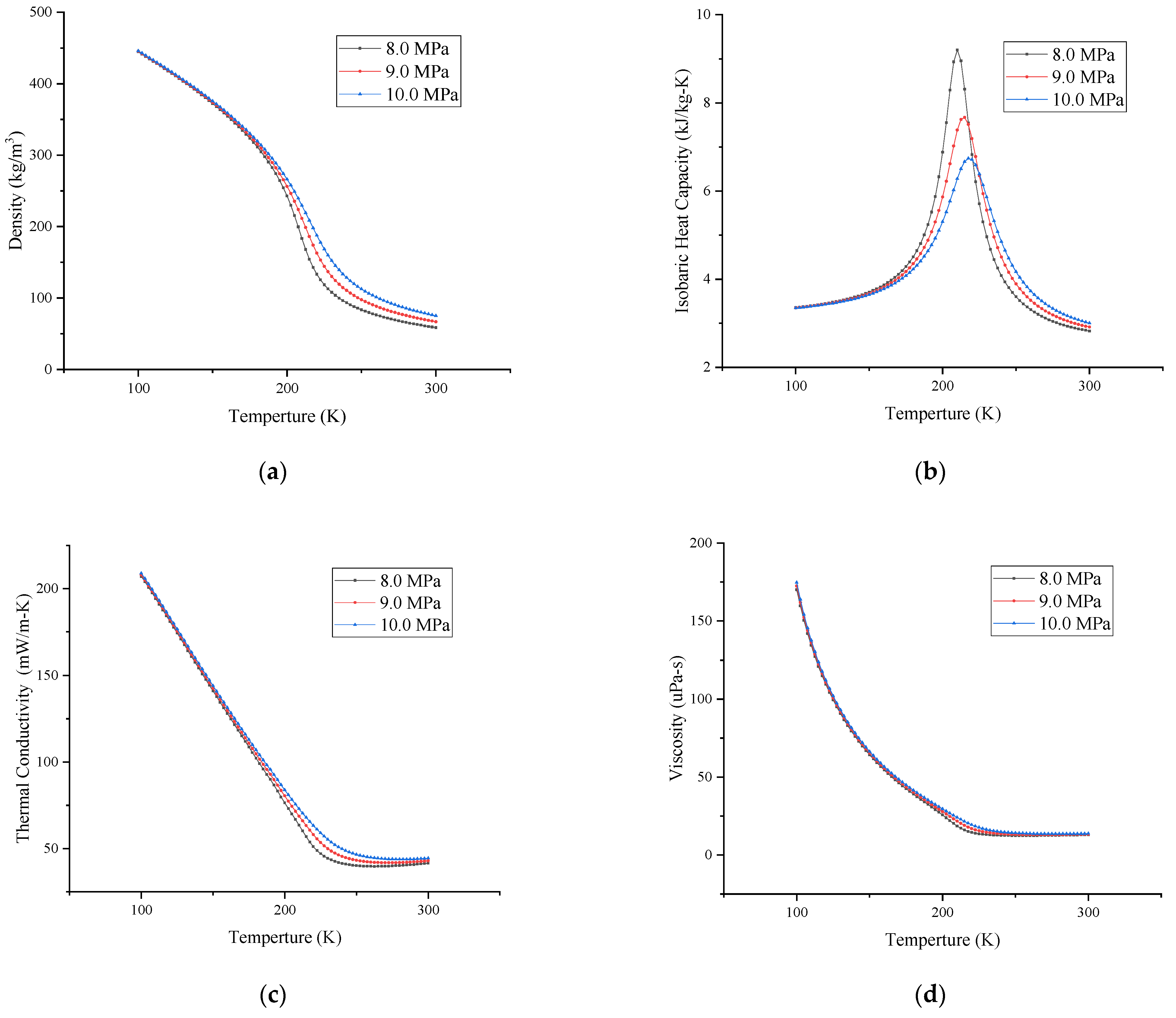
3.3. Thermal Properties of the Working Fluid
4. Results
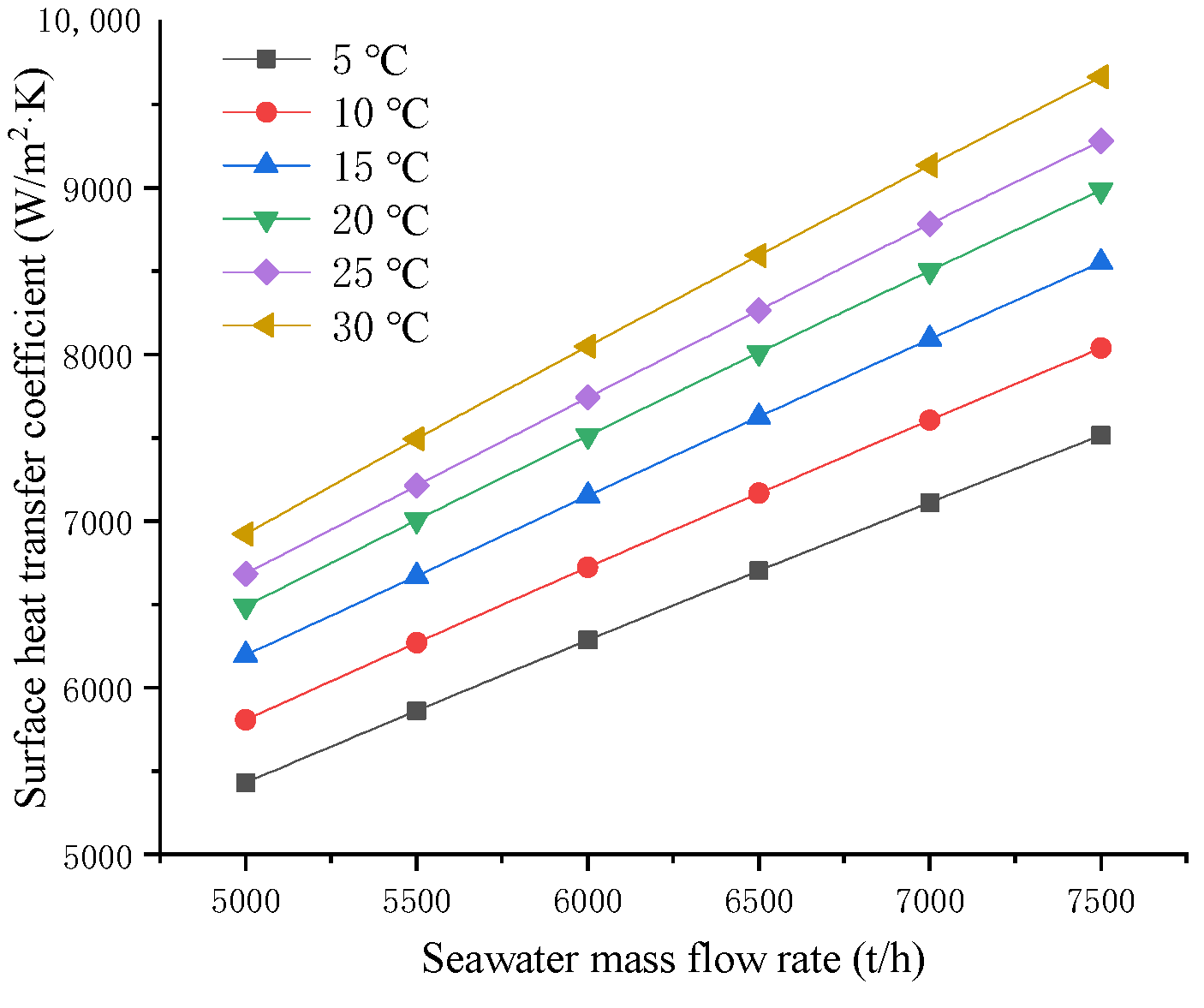
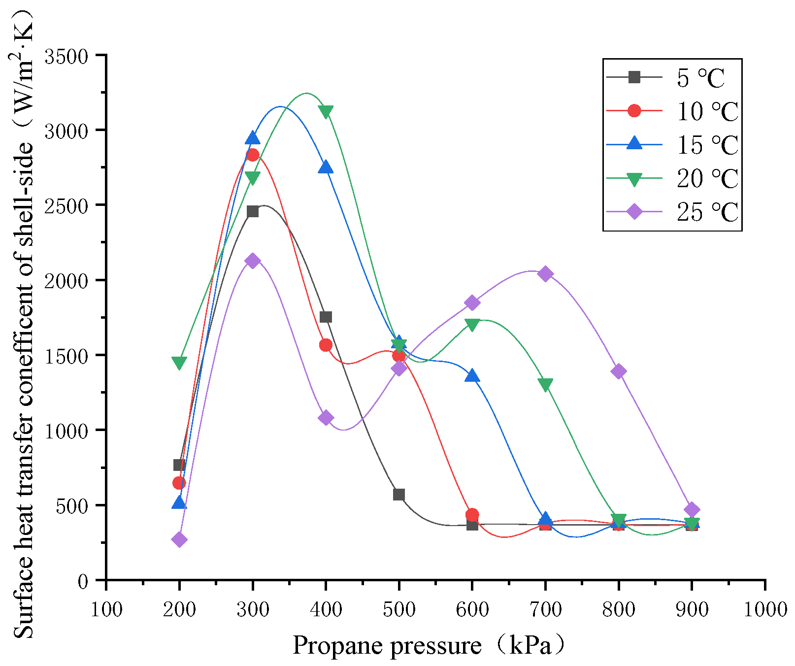
4.1. Calculation Results of Propane Vaporizer
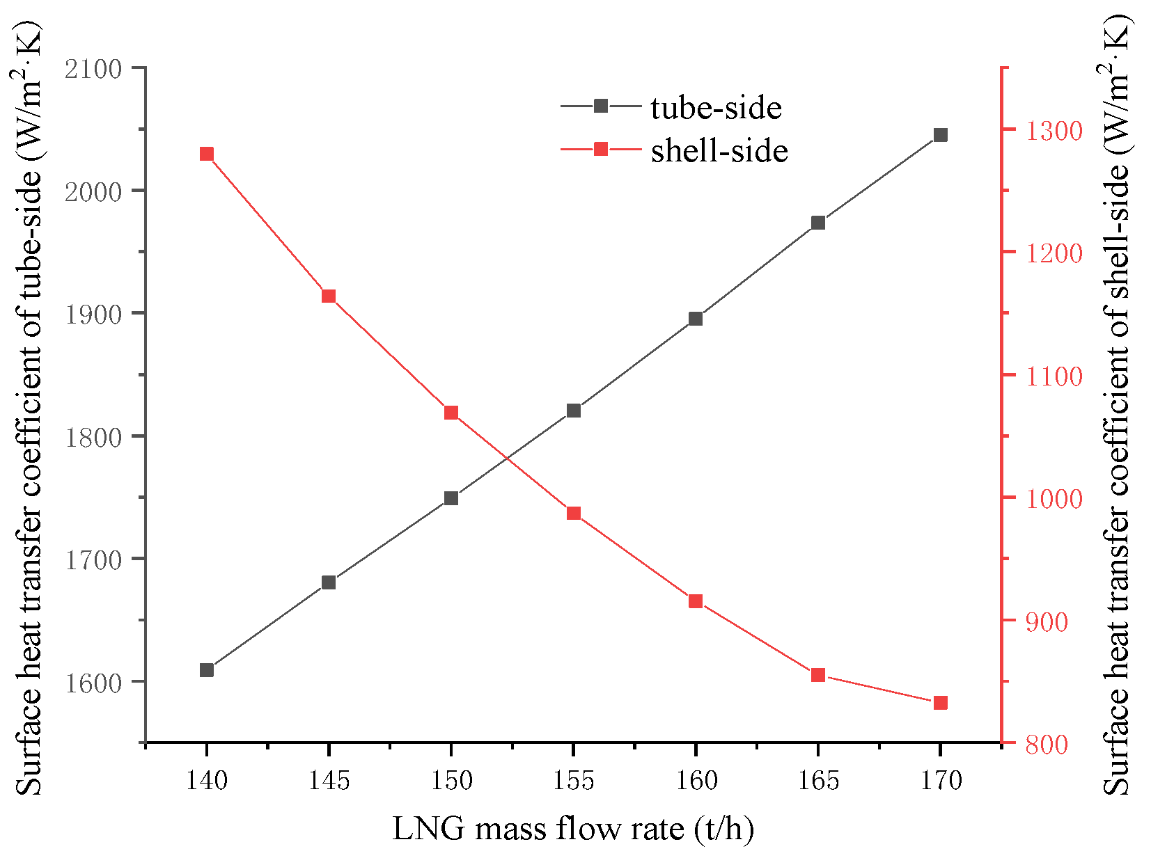
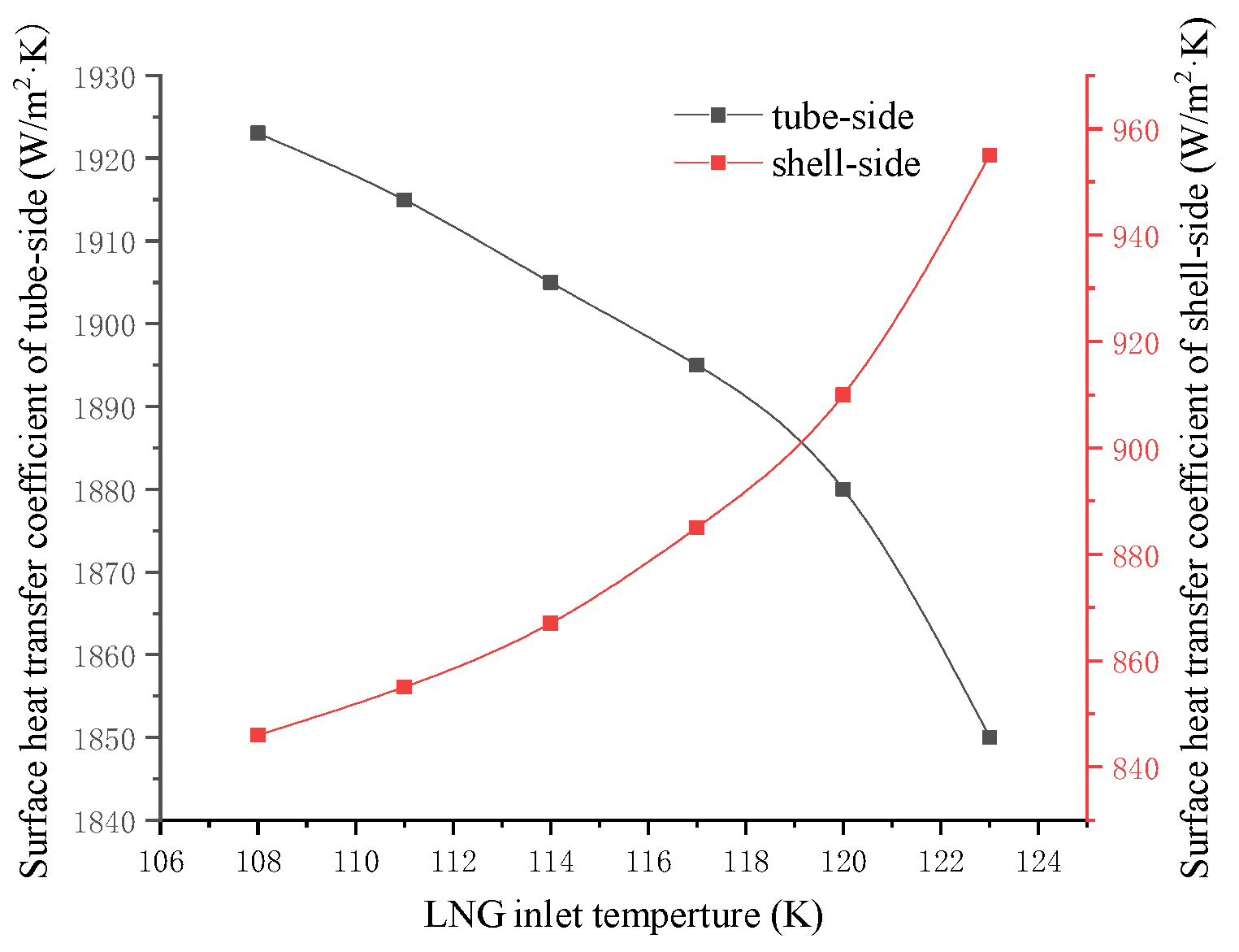
4.2. Calculation Results for the LNG Vaporizer
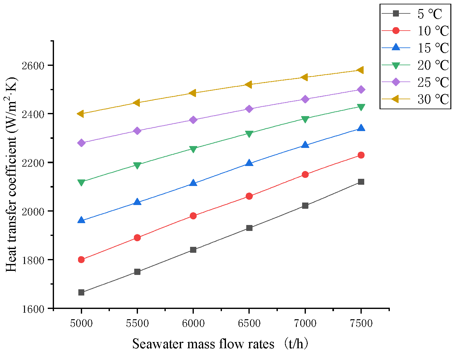
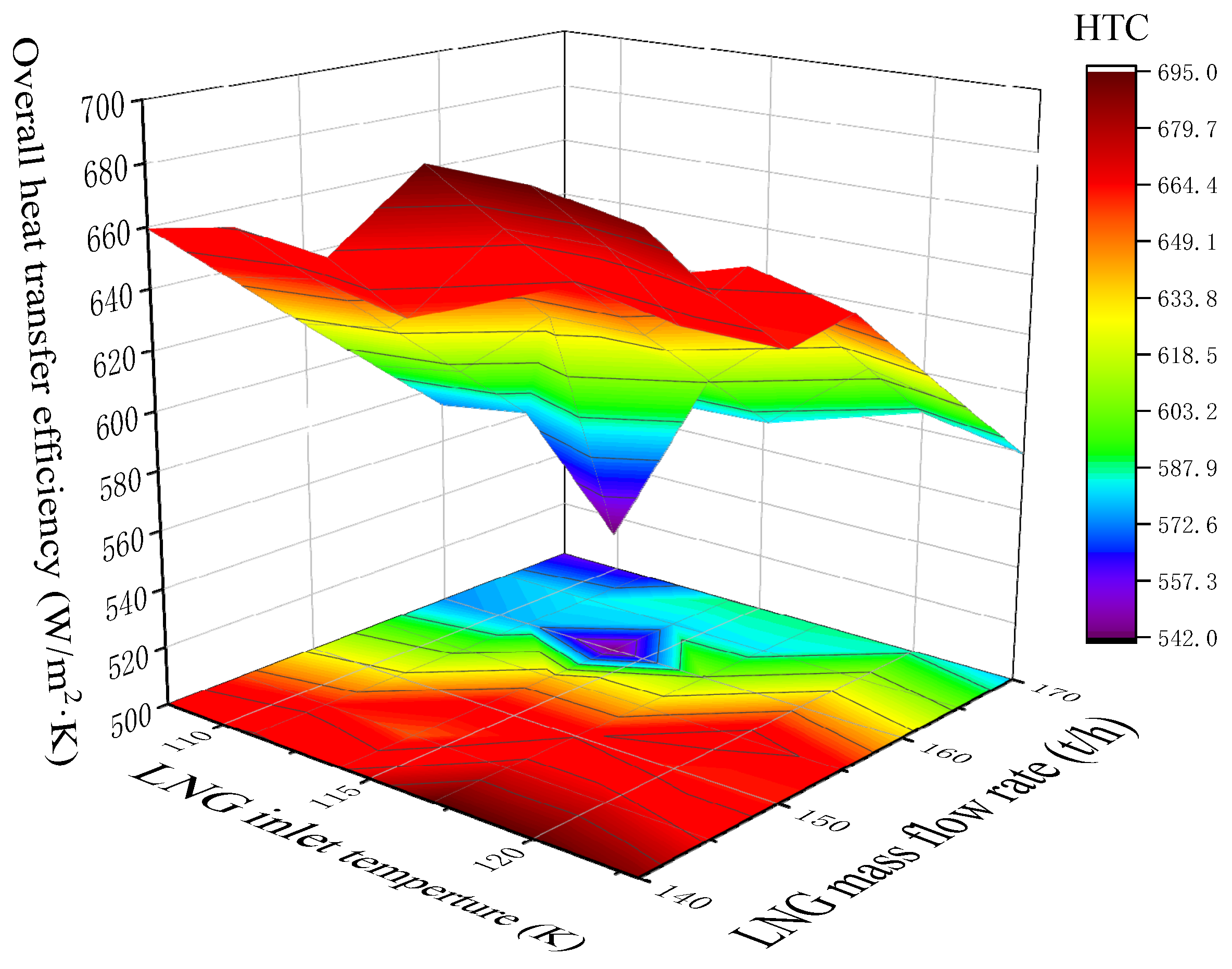
4.3. Calculation Results for the NG Heater
5. Discussion
5.1. Minimum Seawater Flow Rate Analysis of the IFV
5.2. Fitting of the Minimum Seawater Flow Rate
5.3. Optimization Results
6. Conclusions
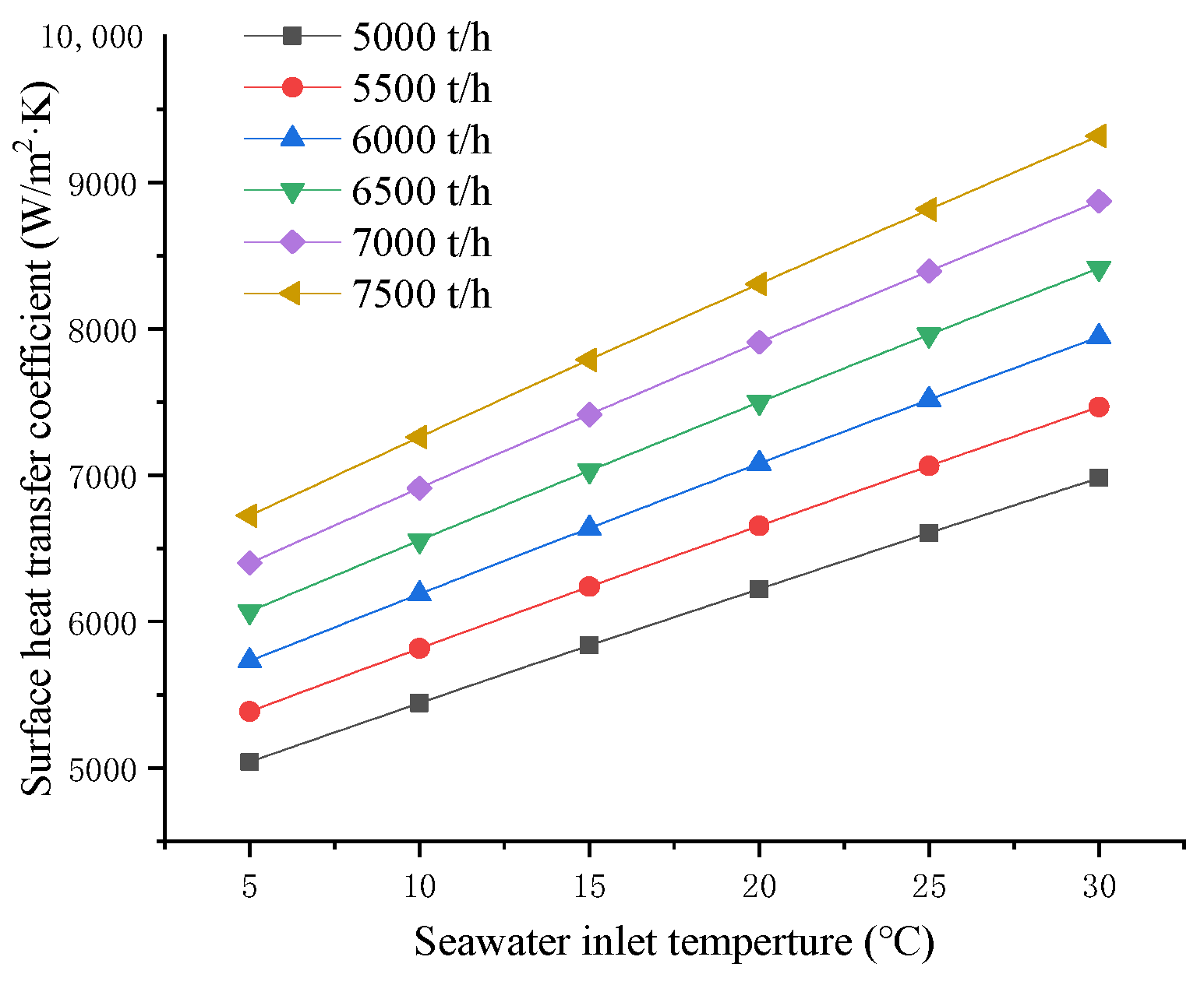
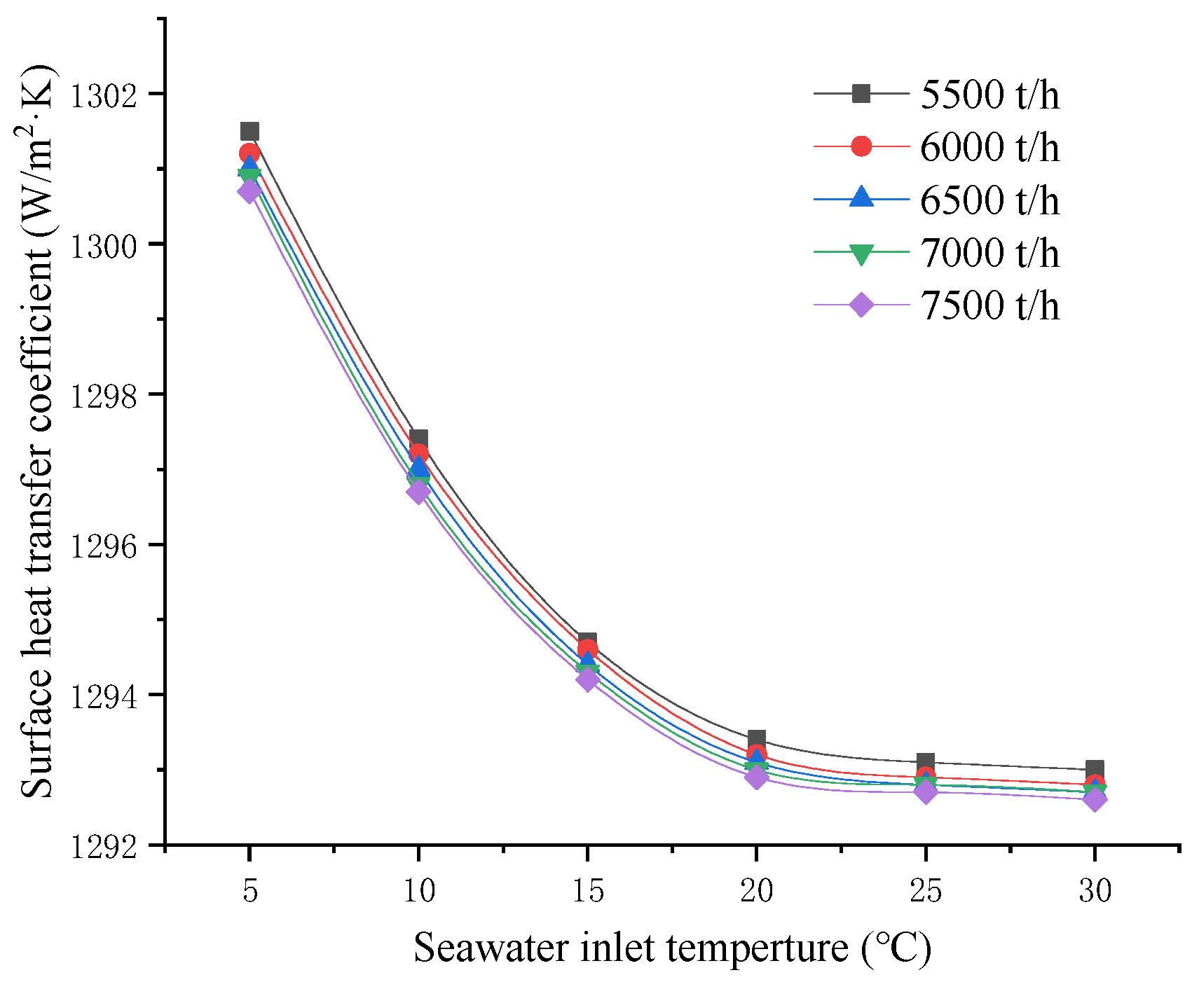
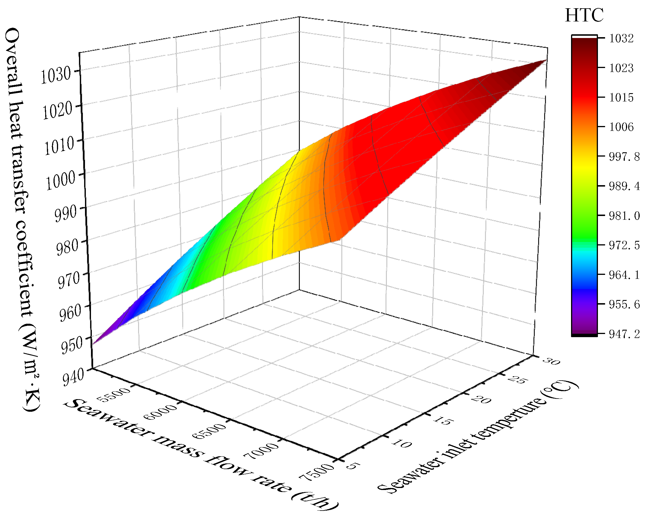
- A heat transfer calculation model was established based on the IFV used in the target LNG terminal investigated in this study, and the IFV was divided into three sections: the LNG vaporizer, the propane vaporizer, and the NG heater. The heat transfer coefficients of each section were calculated according to the corresponding equations. The results showed that with the increase in seawater mass flow rate, the overall heat transfer coefficient increased significantly in E1, increased slowly in E3, and remained almost unchanged in E2; with the increase in seawater temperature and the decrease in seawater viscosity, the overall heat transfer coefficient increased significantly in E1 but remained unchanged in the other two sections; with the increase in the LNG mass flow rate, the overall heat transfer coefficient increased slightly in each section.
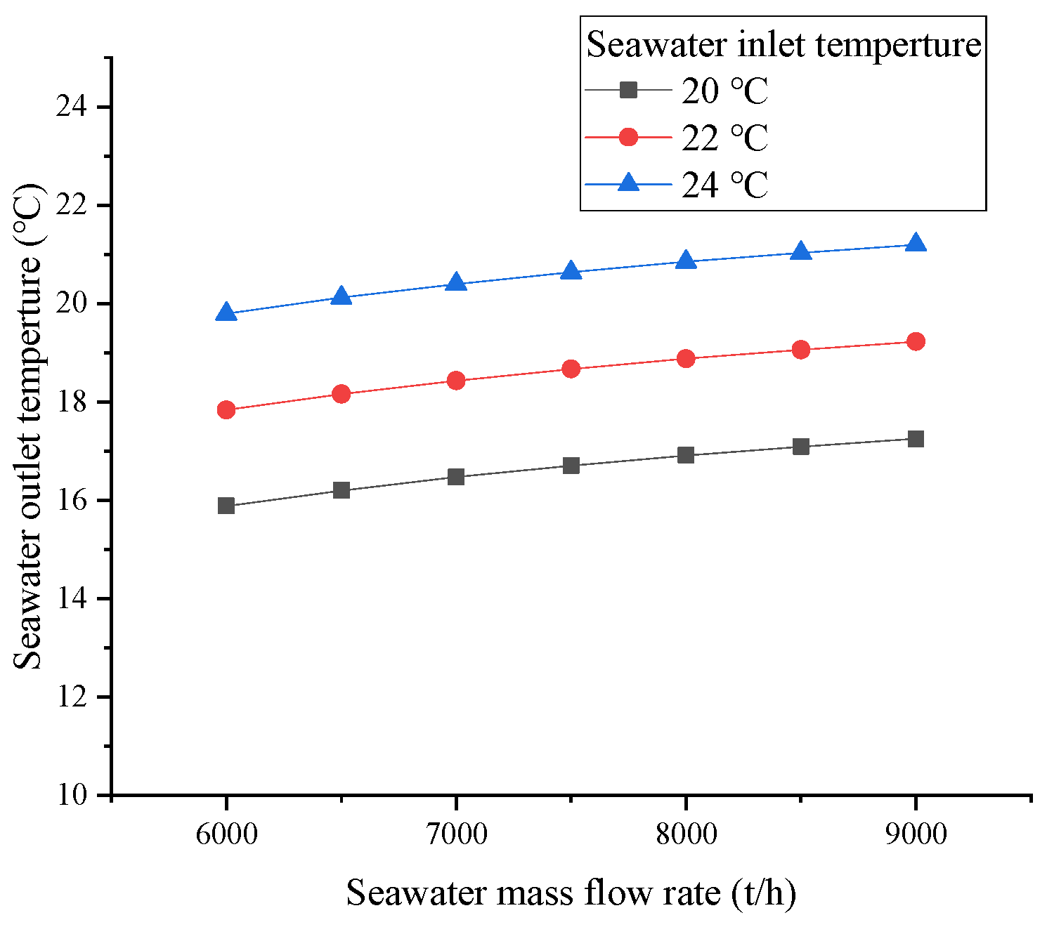
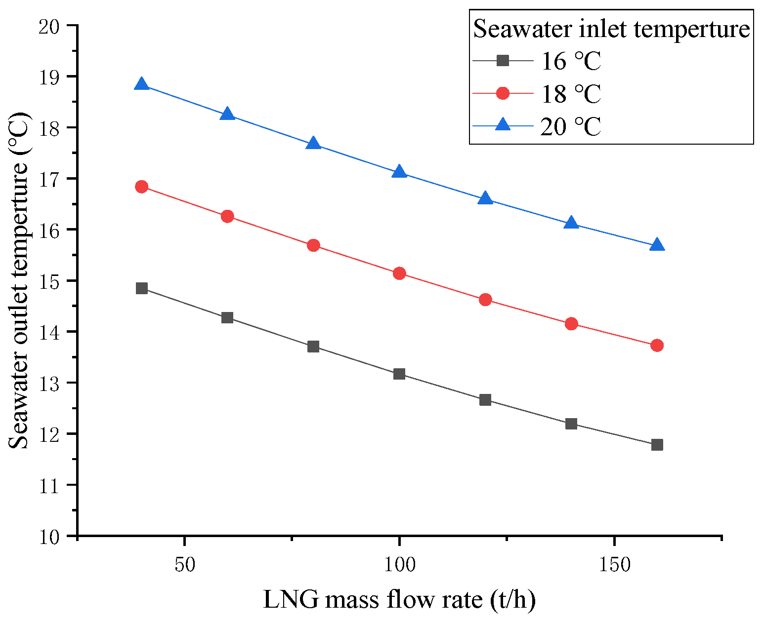
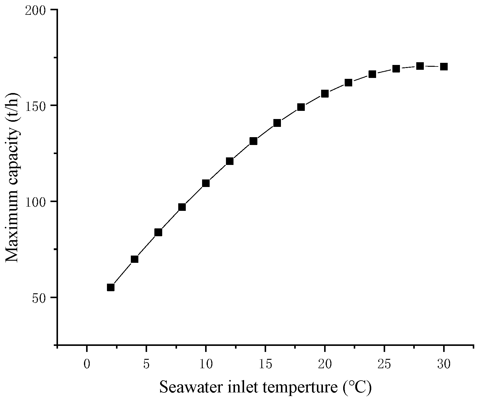
- The KA value of IFV under different conditions was obtained through the results of numerical calculations and then calculated for different operating conditions through HYSYS. The calculation results showed that the decrease in seawater flow rate or the increase in LNG flow rate increased the temperature difference between the inlet and outlet of seawater, and thus, the maximum processing capacity and minimum seawater flow rate of the IFV under various working conditions were calculated. The NG outlet temperature increased with the increase in the seawater inlet temperature and decreased with the decrease in the LNG flow rate. However, the seawater flow had little effect on the NG outlet temperature. Therefore, when the equipment was operating at the lower limit of seawater flow, if the NG outlet temperature did not meet the demand for external transportation, reducing the LNG flow was the best method.
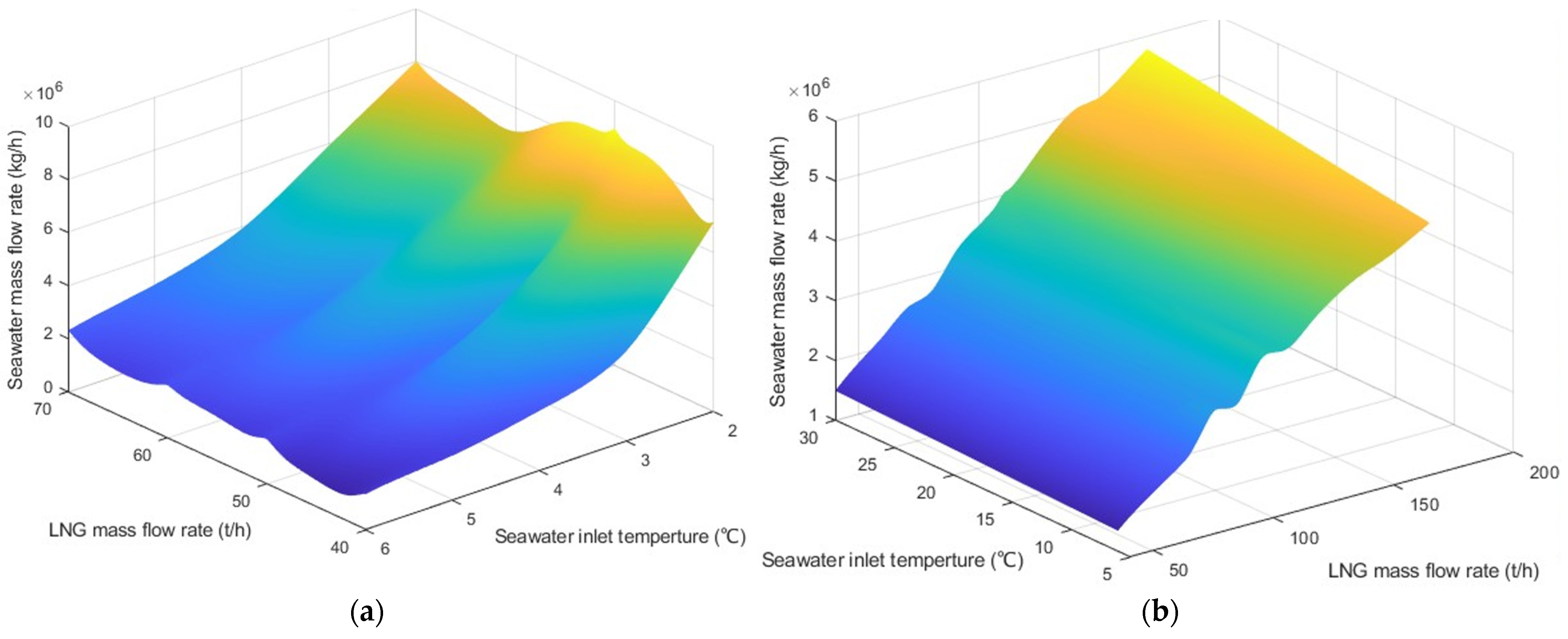
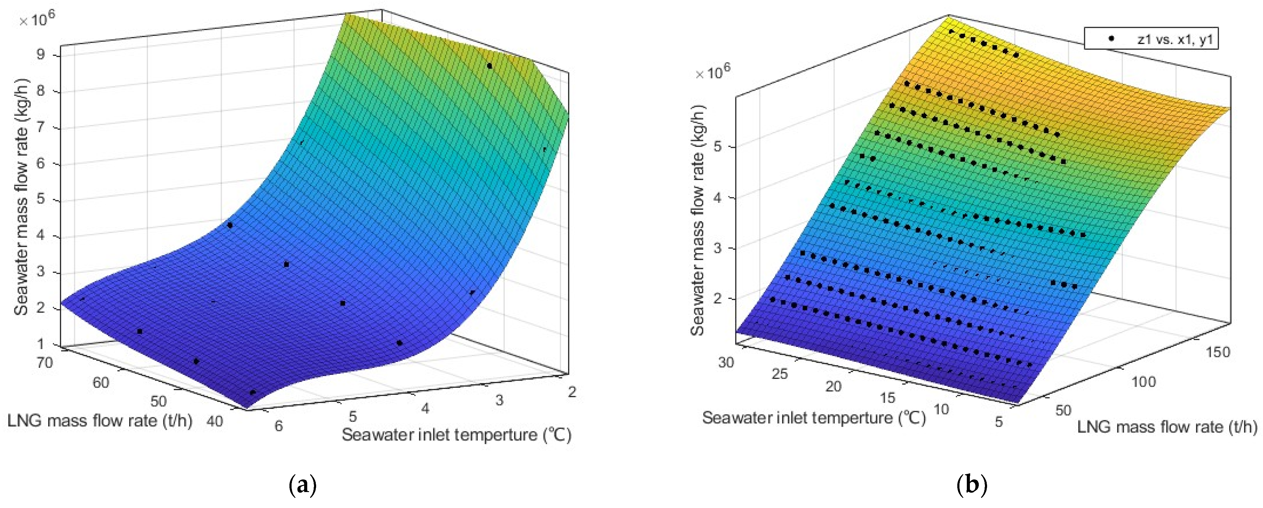
- Based on the results of the minimum seawater flow analysis, the relationship between the minimum seawater flow rate, seawater temperature, and the LNG flow rate was fitted using MATLAB. Due to the physical characteristics of seawater and IFV operation requirements, two cases of seawater inlet temperatures higher than 6 °C and lower than 6 °C were fitted separately, and finally, the two binary cubic polynomials listed in the study were obtained.
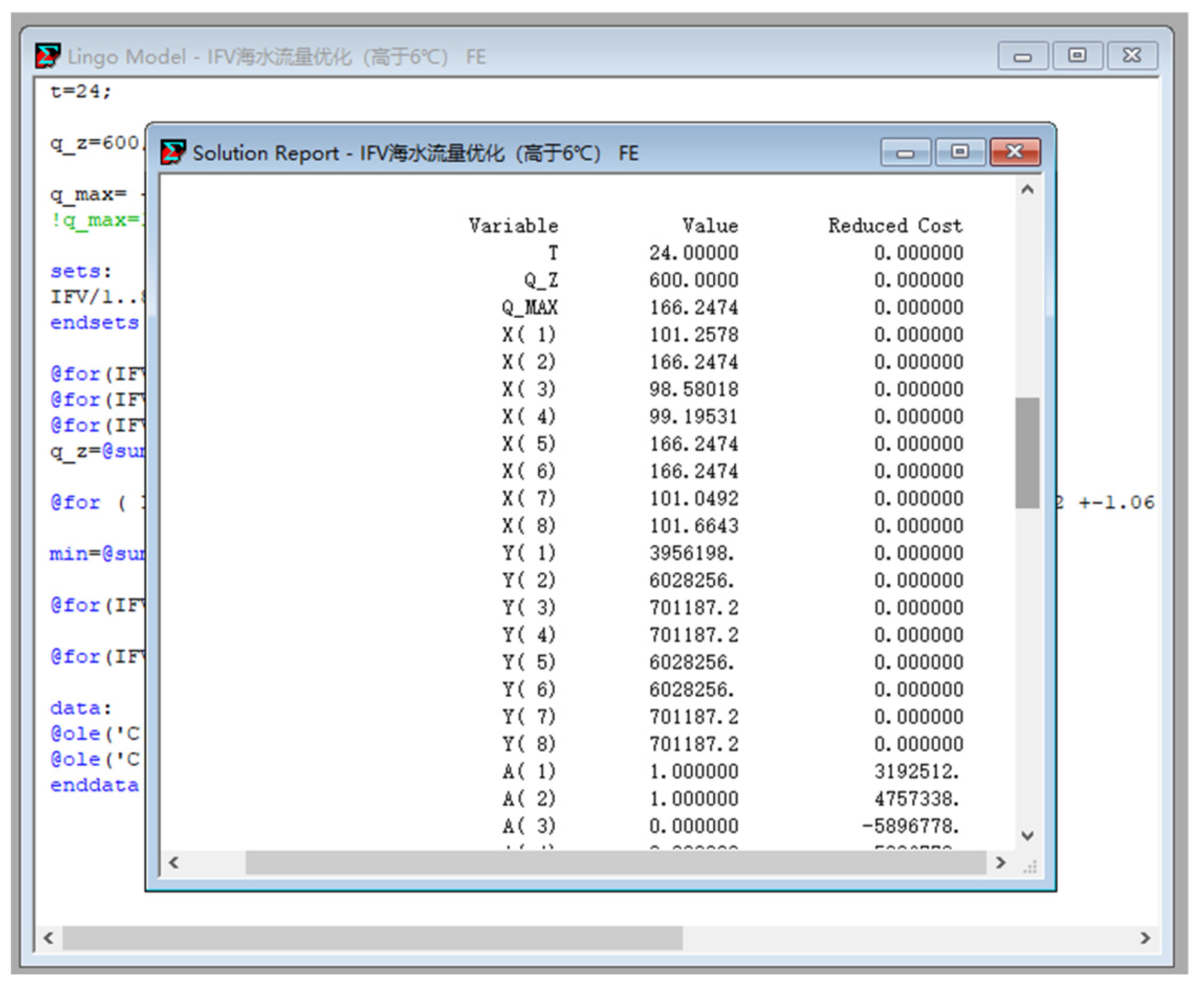
- When operating an LNG terminal, the seawater flow rate and LNG flow rate of the IFV should be flexibly adjusted according to different seawater temperatures and transmission demands. The optimal IFV operation configuration method for different conditions was found using the programming calculations of the software used in this study. After inputting the seawater temperature and the total transmission volume, the LNG flow rate and seawater flow rate allocation of each IFV in the regasification system were calculated so that the consumption of seawater in the regasification system was minimized. It ensures that the heat in seawater was fully utilized, effectively reduced the consumption of seawater, and provided a reference for the operation of the LNG terminal.
Author Contributions
Funding
Data Availability Statement
Conflicts of Interest
Abbreviations
| Nu | Nusselt number; |
| Re | Reynolds number; |
| Pr | Prandtl number; |
| q | Heat flux density, W/m2; |
| Mr | Molar mass, kg/kmol; |
| Pc | Critical pressure of the fluid, kPa; |
| P | Saturation pressure of the fluid, kPa; |
| n | Dimensionless coefficient; |
| Rp | Average surface roughness, μm; |
| ρ | Density, kg/m3; |
| Cpb | Constant pressure-specific heat capacity, J/(kg·K); |
| T | Temperature, K; |
| g | Acceleration of gravity, m/s2; |
| λ | Thermal conductivity, W/(m·K); |
| r | Latent heat of vaporization, J/kg; |
| μ | Dynamic viscosity, Pa·s; |
| d | Diameter, m; |
| Tsat | Saturation temperature of propane, K; |
| s1 | Longitudinal tube pitch, m; |
| s2 | Transversal tube pitch, m; |
| h | Surface heat transfer coefficient, W/(m2·K); |
| Lc | Characteristic length, m; |
| kf | Thermal conductivity of the fluid, W/(m·K); |
| L | Length of the circular tube, m; |
| A | Surface area of the outer wall of the tube, m2; |
| K | Overall heat transfer coefficient, W/(m2·K) |
| G | Total seawater flow rate of the regasification system, t/h; |
| a | Total number of IFVs; |
| xi | Operating status of the ith IFV; |
| t | Seawater inlet temperature of the IFV, °C; |
| qi | LNG flow rate of the ith IFV, t/h; |
| qmin | Minimum LNG flow rate of the IFV, t/h; |
| qmax | Maximum LNG flow rate of the IFV, t/h; |
| Qm | Output demand of the LNG regasification system, t/h. |
| Subscript | |
| f | Based on the fluid; |
| w | Based on the tube wall; |
| pc | Pseudo-critical value; |
| b | Average value; |
| w | Based on the tube wall; |
| i | Based on the inside tube; |
| o | Based on the outside tube; |
| ev | Propane vaporizer; |
| co | LNG vaporizer; |
| l | Based on the saturated liquid; |
| g | Based on the saturated vapor. |
| Abbreviation | |
| IFV | Intermediate fluid vaporizer; |
| LNG | Liquefied natural gas; |
| NG | Natural gas; |
| HTC | Heat transfer coefficient; |
| E1 | Propane vaporizer; |
| E2 | LNG vaporizer; |
| E3 | NG heater. |
References
- Wen, C.; Cao, X.; Yang, Y. Swirling flow of natural gas in supersonic separators. Chem. Eng. Process. Process Intensif. 2011, 50, 644–649. [Google Scholar] [CrossRef]
- Wen, C.; Cao, X.; Yang, Y.; Li, W. Numerical simulation of natural gas flows in diffusers for supersonic separators. Energy 2012, 37, 195–200. [Google Scholar] [CrossRef]
- Yang, Y.; Wen, C.; Wang, S.; Feng, Y. Numerical simulation of real gas flows in natural gas supersonic separation processing. J. Nat. Gas Sci. Eng. 2014, 21, 829–836. [Google Scholar] [CrossRef]
- He, T.; Ju, Y. Design and optimization of a novel mixed refrigerant cycle integrated with NGL recovery process for small-scale LNG plant. Ind. Eng. Chem. Res. 2014, 53, 5545–5553. [Google Scholar] [CrossRef]
- Vatani, A.; Mehrpooya, M.; Tirandazi, B. A novel process configuration for coproduction of NGL and LNG with low energy requirement. Chem. Eng. Process. Process. Intensif. 2013, 63, 16–24. [Google Scholar] [CrossRef]
- Wang, M.; Zhang, J.; Xu, Q. A novel conceptual design by integrating NGL recovery and LNG regasification processes for maximum energy savings. AIChE J. 2013, 59, 4673–4685. [Google Scholar] [CrossRef]
- Gu, G.; Zheng, H.; Tong, L. Does carbon financial market as an environmental regulation policy tool promote regional energy conservation and emission reduction? Empirical evidence from China. Energy Policy 2022, 163, 112826. [Google Scholar] [CrossRef]
- Achtnicht, M.; Germeshausen, R.; von Graevenitz, K. Does the stick make the carrot more attractive? State mandates and uptake of renewable heating technologies. Reg. Sci. Urban Econ. 2022, 92, 103753. [Google Scholar] [CrossRef]
- Domon, S.; Hirota, M.; Kono, T. The long-run effects of congestion tolls, carbon tax, and land use regulations on urban CO2 emissions. Reg. Sci. Urban Econ. 2022, 92, 103750. [Google Scholar] [CrossRef]
- Dendy, T.; Nanda, R. Utilization of atmospheric heat exchangers in LNG vaporization processes: A comparison of systems and methods. In Proceedings of the 2008 AIChE Spring Meeting and 235th ACS National Meeting, New Orleans, LA, USA, 6–10 April 2008. [Google Scholar]
- Liu, F.-X.; Dai, Y.-Q. Feasibility of intermediate fluid vaporizer with spiral wound tubes. China Petroleum Process. Petrochem. Technol. 2013, 15, 73–77. [Google Scholar]
- Patel, D.; Mak, J.; Rivera, D.; Angtuaco, J. LNG vaporizer selection based on site ambient conditions. In Proceedings of the 17th International Conference & Exhibition on Liquefied Natural Gas, Houston, TX, USA, 16–19 April 2013. [Google Scholar]
- Kosuke, H.; Chieko, K.; Shigeru, K. Feasibility analysis for intermediated fluid type LNG vaporizers using R32 and R410A considering fluid properties. Int. J. Refrig. 2020, 118, 325–335. [Google Scholar]
- Egashira, S. LNG Vaporizer for LNG Re-gasification Terminal. Kobelco Technol. Rev. 2013, 32, 64–69. [Google Scholar]
- Wang, S.; Han, H.; Li, Y. Parameters optimization of intermediate fluid vaporizer based on mixed working fluid. Oil Gas Storage Transp. 2020, 39, 104–111. [Google Scholar]
- Pu, L.; Qu, Z.-G.; Bai, Y.-H.; Qi, D.; Song, K.; Yi, P. Thermal performance analysis of intermediate fluid vaporizer for liquefied natural gas. Appl. Therm. Eng. 2014, 65, 564–574. [Google Scholar] [CrossRef]
- Liu, F.; Li, H. Development and manufacture of LNG intermediate fluid vaporizer used in sea water condition. Chem. Ind. Eng. Prog. 2015, 34, 99–103. [Google Scholar]
- Song, K.; Yi, P. Heat transfer analysis of intermediate fluid vaporizer. Chem. Engineering. Equip. 2012, 10, 75–77. [Google Scholar]
- Wang, B.-J.; Kuang, Y.-W. Analysis of heat transfer to supercritical LNG in intermediate fluid vaporizer. CIESC J. 2015, 66, 220–225. [Google Scholar]
- Chen, Z. Optimized Design of Heat Transfer Enhancement of LNG Intermediate Fluid Heat Exchanger. Master’s Thesis, South China University of Technology, Guangzhou, China, 2017. [Google Scholar]
- Song, Y.; Ji, X.; Lin, W. Numerical simulation of heat transfer process within sub-cooled intermediate fluid vaporizer. CIESC J. 2015, 66, 62–65. [Google Scholar]
- Sohn, Y.; Kim, S.; Yoon, I. Conceptual design of LNG FSRU topside regasification plant. In Proceedings of the 22nd International Offshore and Polar Engineering Conference, Rhodes, Greece, 17–22 June 2012. [Google Scholar]
- Devotta, S.; Patil, S.R.; Sawant, N.N.; Kulkarni, M.M. Comparative life cycle testing of hermetic compressors with CFC-12 and HC-blend. In Proceedings of the International Conference on Ozone Protection Technologies, Baltimore, MD, USA, 12–13 November 1997. [Google Scholar]
- Fine, A. Field testing of CFC-free, energy efficient refrigerators in China. In Proceedings of the International Conference on Ozone Protection Technologies, Baltimore, MD, USA, 12–13 November 1997. [Google Scholar]
- Palm, B. Hydrocarbons as refrigerants in small heat pump and refrigeration systems—A review. Int. J. Refrig. 2008, 31, 552–563. [Google Scholar] [CrossRef]
- Jung, D.; Park, B.; Lee, H. Evaluation of supplementary/retrofit refrigerants for automobile air-conditioners charged with CFC12. Int. J. Refrig. 1999, 22, 558–568. [Google Scholar] [CrossRef]
- Kruse, H. The state of the art of the hydrocarbon technology in household refrigeration. In Proceedings of the International Conference on Ozone Protection Technologies, Washington, DC, USA, 21–23 October 1996. [Google Scholar]
- Li, L.-S. Research progress on alternative refrigerants and their development trend. J. Refrig. 2011, 32, 53–58. [Google Scholar]
- Wang, B.; Wang, W. Simulation of performance of intermediate fluid vaporizer under wide operation conditions. Front. Energy 2020, 14, 452–462. [Google Scholar] [CrossRef]
- Mena, J.B.; Tiecher, R.F.P.; Esteves, A.S. Thermodynamic study of the simultaneous production of electrical power and refrigeration capacity from regasification of liquefied natural gas. Appl. Therm. Eng. 2018, 140, 564–579. [Google Scholar] [CrossRef]
- Peng, C.; Liu, J.-Z. LNG terminal gasifier combined operation plan in winter. Chem. Ind. Manag. 2014, 11, 145. [Google Scholar]
- Yamamoto, S.; Ueno, Y.; Terada, S.; Nakaoki, K.; Sugino, K. Vaporizer for a Low Temperature Liquid. U.S. Patent 6367265 B1, 9 April 2002. [Google Scholar]
- Dittus, F.; Boelter, L. Heat transfer in automobile radiators of the tubular type. Int. J. Heat Mass Transf. 1930, 2, 443–461. [Google Scholar] [CrossRef]
- Cooper, M.G. Saturation nucleate pool boiling-a simple correlation. In First U.K. National Conference on Heat Transfer; Elsevier: Amsterdam, The Netherlands, 1984; pp. 785–792. [Google Scholar]
- Wang, Y.Z.; Hua, Y.X.; Meng, H. Numerical studies of supercritical turbulent convective heat transfer of cryogenic-propellant methane. J. Thermophys. Heat Transf. 2010, 24, 490–500. [Google Scholar] [CrossRef]
- Nikitin, K.; Kato, Y.; Ishizuka, T. Steam condensing-liquid CO2 boiling heat transfer in a steam condenser for a new heat recovery system. Int. J. Heat Mass Transf. 2008, 51, 4544–4550. [Google Scholar] [CrossRef]
- Jung, D.; Chae, S.; Bae, D. Condensation heat transfer coefficients of flammable refrigerants. Int. J. Refrig. 2004, 27, 314–317. [Google Scholar] [CrossRef]
- Žukauskas, A. Heat transfer from tubes in crossflow. Adv. Heat Transf. 1972, 8, 93–160. [Google Scholar]
- Qin, Z.; Liu, C.; Cao, K.; Men, Q.; Du, K. Numerical Simulation on the Boiling Heat Transfer Performance of the GEWA-T. Chem. Equip. Technol. 2016, 05, 47–51. [Google Scholar]
- Ye, Z.C.; Mo, X.Y.; Zhao, L. MINLP Model for Operational Optimization of LNG receiving terminals. Processes 2021, 9, 599. [Google Scholar] [CrossRef]
- Li, K.R.; Zuo, K.; Wang, J.N.; Gao, W.Y. Dynamic Programming Example Analysis of a Pump Station. In Proceedings of the International Colloquium on Computing, Communication, Control, and Management (CCCM 2010), Yangzhou, China, 20–22 August 2010; pp. 1796–1800. [Google Scholar]
- Zheng, W.; Zhu, J.; Luo, Q. Distributed dispatch of integrated electricity-heat systems with variable mass flow. IEEE Trans. Smart Grid 2022. [Google Scholar] [CrossRef]
- Xu, S.Q.; Cheng, Q. LNG vaporizers using various refrigerants as intermediate fluid: Comparison of the required heat transfer area. J. Nat. Gas Sci. Eng. 2015, 25, 1–9. [Google Scholar] [CrossRef]
- Zhu, J.; Zhu, Z. Shear wall structural optimization study based on LINGO and virtual work principle. Build. Sci. 2020, 36, 52–58. [Google Scholar]
- Costa, M.F.P.; Rocha, A.M.A.C.; Fernandes, E.M.G.P. Continuous Relaxation of MINLP Problems by Penalty Functions: A Practical Comparison. In Proceedings of the 17th International Conference on Computational Science and its Applications (ICCSA), Trieste, Italy, 3–6 July 2017; pp. 107–118. [Google Scholar]


| Parameter | Value | Parameter | Value |
|---|---|---|---|
| LNG inlet temperature (°C) | −160 | E2 number of heat exchange tubes | 810 |
| LNG inlet pressure (MPa) | 9.91 | E2 heat exchange tube length (mm) | 9000 |
| LNG outlet pressure (MPa) | 9.71 | E2 heat exchange tube outer diameter (mm) | 15.9 |
| NG output temperature (°C) | ≥1 | E2 heat exchange tube wall thickness (mm) | 1.6 |
| Number of vaporizers | 8 | E2 heat exchange area (m2) | 1018.4 |
| E1 number of heat exchange tubes | 3152 | E3 number of heat exchange tubes | 2893 |
| E1 heat exchange tube length (mm) | 9008 | E3 heat exchange tube length (mm) | 3910 |
| E1 heat exchange tube outer diameter (mm) | 19.05 | E3 heat exchange tube outer diameter (mm) | 19.05 |
| E1 heat exchange tube wall thickness (mm) | 1.2 | E3 heat exchange tube wall thickness (mm) | 2 |
| E1 heat exchange area (m2) | 1908.2 | E3 heat exchange area (m2) | 805.94 |
| IFV (A) | IFV (B) | IFV (C) | IFV (D) | IFV (E) | IFV (F) | IFV (G) | IFV (H) | Total | ||
|---|---|---|---|---|---|---|---|---|---|---|
| Before | QLNG | 103.7 | 101.8 | 104.6 | 123.7 | 120.5 | 0 | 104.6 | 123.7 | 782.6 |
| QSW | 6776.2 | 6596.7 | 7365.3 | 6223.1 | 6723.8 | 0 | 6288.7 | 6254.7 | 46228 | |
| After | QLNG | 109.4 | 109.4 | 109.4 | 109.4 | 109.4 | 109.4 | 65.3 | 65.3 | 787 |
| QSW | 4786.3 | 4786.3 | 4786.3 | 4786.3 | 4786.3 | 4786.3 | 2866.6 | 2866.6 | 34,451 | |
| IFV (A) | IFV (B) | IFV (C) | IFV (D) | IFV (E) | IFV (F) | IFV (G) | IFV (H) | Total | ||
|---|---|---|---|---|---|---|---|---|---|---|
| Before | QLNG | 136.1 | 139.9 | 0 | 29.6 | 154.6 | 0 | 0 | 25.6 | 485.8 |
| QSW | 6929.4 | 7088.9 | 0 | 6662.1 | 7164.6 | 0 | 0 | 5725.5 | 33,570 | |
| After | QLNG | 147.6 | 169.1 | 169.1 | 0 | 0 | 0 | 0 | 0 | 485.8 |
| QSW | 6202.2 | 5667.9 | 5667.9 | 0 | 0 | 0 | 0 | 0 | 15,943 | |
Disclaimer/Publisher’s Note: The statements, opinions and data contained in all publications are solely those of the individual author(s) and contributor(s) and not of MDPI and/or the editor(s). MDPI and/or the editor(s) disclaim responsibility for any injury to people or property resulting from any ideas, methods, instructions or products referred to in the content. |
© 2023 by the authors. Licensee MDPI, Basel, Switzerland. This article is an open access article distributed under the terms and conditions of the Creative Commons Attribution (CC BY) license (https://creativecommons.org/licenses/by/4.0/).
Share and Cite
Huang, K.; Zhou, X.; Huang, C.; Wang, L.; Li, D.; Zhao, J. Heat Transfer Analysis and Operation Optimization of an Intermediate Fluid Vaporizer. Energies 2023, 16, 1383. https://doi.org/10.3390/en16031383
Huang K, Zhou X, Huang C, Wang L, Li D, Zhao J. Heat Transfer Analysis and Operation Optimization of an Intermediate Fluid Vaporizer. Energies. 2023; 16(3):1383. https://doi.org/10.3390/en16031383
Chicago/Turabian StyleHuang, Kun, Xingyu Zhou, Cheng Huang, Lin Wang, Dequan Li, and Jinrei Zhao. 2023. "Heat Transfer Analysis and Operation Optimization of an Intermediate Fluid Vaporizer" Energies 16, no. 3: 1383. https://doi.org/10.3390/en16031383
APA StyleHuang, K., Zhou, X., Huang, C., Wang, L., Li, D., & Zhao, J. (2023). Heat Transfer Analysis and Operation Optimization of an Intermediate Fluid Vaporizer. Energies, 16(3), 1383. https://doi.org/10.3390/en16031383


