Article

Nonimaging High Concentrating Photovoltaic System Using Trough

1
Department of Electrical Engineering, School of Engineering, University of Management and Technology, C-II, Johar Town, Lahore 54770, Pakistan
2
Department of Information and Communication Engineering, College of ICT Convergence, Myongji University, 116 Myongji-ro, Yongin 17058, Gyeonggi-do, Republic of Korea
*
Authors to whom correspondence should be addressed.
Energies 2023, 16(3), 1336; https://doi.org/10.3390/en16031336
Submission received: 17 November 2022 / Revised: 9 January 2023 / Accepted: 20 January 2023 / Published: 27 January 2023

Abstract

:
Solar energy is a long-established technology, which has zero CO2 emissions, and provides low-cost energy for a given area of land. The concentrator photovoltaic (CPV) has been given preference over the photovoltaic due to its high efficiency. In a CPV system, most of the solar cell area has been replaced with an optical concentrator. Various parabolic trough based CPV systems have been presented where a concentration of <300 is achieved. In the current research, a design is presented to achieve a high concentration of 622×. The design consists of two stages of concentration including parabolic trough as a main concentrator and nonimaging reflective grooves as a secondary concentrator. The trough reflects the incident light towards the secondary reflector where the light is redirected over the solar cell. Design of the two-stage concentrator, ray-tracing simulation, and results are presented. The system achieved an optical efficiency of 79%. The system would also be highly acceptable in solar thermal applications owing to its high concentration.

1. Introduction

Energy consumption has been increased in different sectors worldwide, such as residential and commercial buildings, vehicles, and industry. World energy demand is mainly fulfilled by fossil fuels that are costly and hazardous sources to feed the energy need and have serious threats for the sustainable development. Current problem is not just accomplishing the energy ultimatum, but to provide a safer environment to the future generations. Generation units have made efforts to deal with recent challenges in the energy sector to minimize the demand and supply gap. The resources for energy generation, such as water, coal, gas, nuclear energy, and oil are used to meet the energy demand. The energy generation from oil and gas thermal plants carry hazardous gases and other pollutants [1]. Renewable energy has been widely used all over the world to reduce CO2 emission. It does not require any purchasable primary fuel in contrast with the traditional fossil fuels such as coal, oil, and gas. International Energy Agency projected that PV and wind energy to be increased up to 500 gigawatts by 2030 [2]. Among all these resources, solar energy is readily available and adopted as a long-lasting technology. Different technologies have been used to produce energy from the solar spectrum, such as PV, CPV, and thermal [3,4]. Conversion of photons (sunlight) into electrical energy is a fundamental principal of PV technology. Semiconductor materials (e.g., silicon, germanium, and gallium) are used to develop PV cells. Solar cells, such as crystalline Si, amorphous silicon, perovskite crystals, multi-junction (MJ), and thin film, have been developed to be used for various applications [5,6,7]. Among these, MJ cells provide high efficiency. In MJ cells, different junctions (GaAs, AlInP, InGaP, AlGaInP, InGaAs, and Ge) absorb different wavelengths of light to produce the output while single junction cell absorbs a particular band and rest of the wavelengths are unused [8]. Extreme attainable efficiency of 46% was noted using four-junction cell [9,10].
CPV systems have been promoted due to their higher efficiency compared to the PV systems. The CPV system requires less area of solar cell by increasing geometrical concentration and providing high efficiency, thus reducing cost of the system [11,12,13]. Optical concentrators, such as parabolic concentrator, parabolic trough, CPC, heliostats, convex lens, and Fresnel lens, were used in the CPV systems [14,15,16,17]. Optical concentrators are used to increase the intensity of light and focus the available light over the solar cell. For a CPV system, reflectors are preferred because of their high efficiency compared to the Fresnel lens. However, Fresnel lens makes the system cost-effective because of its low-cost polymethacrylate material. The parabolic trough produces linear focus while the paraboloidal reflector and Fresnel lens produce point focus. For the solar thermal systems, a linear focus is preferred. However, the point-focus concentrator gives a high concentration. Most of the CPV systems work in direct sunlight, which is achieved using tracking. Both the concentrator and solar cells are mounted with the tracking device. However, the CPV systems can also be designed without sun tracking, but they require complex optics to get higher efficiency. These systems are designed to get high acceptance angle to receive maximum number of rays at all daylight hours. In [14], the CPV system was designed to achieve an acceptance angle of ±15° with a concentration of 39×. The system was designed in such a way that a high concentration could be achieved at the cost of a reduced acceptance angle. The system was preferred for small-scale because of its bio-inspired complexed optical design.
The CPV system includes a primary optical element (POE), secondary optical element (SOE), solar cell, sun tracking, and electrical modules. Sun tracking helps the concentrator to obtain the collimated light at all day [18,19]. Solar concentrators are divided into two main types, imaging and nonimaging concentrators [20]. Imaging concentrators have an exact focal point and it forms an image of the source, while non-imaging optical concentrators do not form an image of the source. Previously, imaging optical devices have been used for achieving a high concentration. Nonimaging concentrators were preferred to redirect the light to the desired surface by improving the uniformity and efficiency of the system [21,22]. Edge-ray principle was used to design the nonimaging concentrators [23] where the edge rays from the concentrator were redirected towards the edges of the receiver. Further, nonimaging concentrators could be designed using freeform optics. Different studies were found in which single-stage, two-stage, and multi-stage concentrations were demonstrated [24]. However, by increasing the stages, the optical efficiency of the system was decreased due to reflection or refraction losses at each stage. Therefore, high efficiency is achieved using minimum number of optical elements. Achieving a uniform irradiance distribution over the receiver along with the efficiency is a main objective in CPV systems. Irradiance distribution (uniform and nonuniform) is one of the key characteristics in the nonimaging CPV systems [25]. By keeping this in view, different studies have been conducted to increase the efficiency of a CPV system by increasing uniform irradiance [17,23,26]. Nonuniform irradiance can affect the cell temperature, fill factor, and mismatch losses [7]. Numerous cooling systems have been developed to improve the performance of the CPV system to maintain the cell temperature [27]. By designing optical methods and geometry of the concentrators, the irradiance uniformity can be improved.
Geometrical concentration is one of the important factors in increasing the efficiency of a CPV system [28]. In [12], the performance of the triple junction solar cells was compared by varying the geometrical concentration using the reflector and lens. Further, the effect of different parameters, such as distance between the reflector/lens and solar cell were also compared. A CPV system was developed using a parabolic trough, which achieved the geometrical concentration of 285 having an optical efficiency of 72% [29]. In this system, a novel nonimaging two-stage optical design was proposed to concentrate the rays at the center of the trough. Development of [29] was presented to increase the irradiance uniformity and acceptance angle using parabolic trough, secondary optics, and CPC [11]. The CPC was introduced to achieve a high concentration at the third-stage, which reduced the size of the solar cell. In [30], a CPV system was analyzed using spherical mirrors, which had achieved better geometrical concentration and optical efficiency as compared to Fresnel lenses. The mirror, having three-times less area, gave a higher efficiency compared to Fresnel lens. A two-stage concentrator was developed [25], in which the paraboloidal reflector achieved lower efficiency in comparison with a hyperboloid as a secondary reflector. Since the surface area of the hyperboloidal reflector was large compared to the paraboloidal reflector’s surface area, the hyperboloidal gave high irradiance over the solar cell. Moreover, the irradiance map of a paraboloidal secondary reflector showed that rays were mainly centered at the middle. The hyperboloid gave a large tracking error compared to the paraboloidal design. In [31], a stable CPV system consisted of parabolic concentrator produced 17–65-watt output power from the geometrical concentration of 1–10× using parabolic concentrator. Recently, feasibility of a 120 m2 CPV system was developed as a domestic energy solution in Italy whose acceptance angle was noted as ±0.46 [32]. The experiment was conducted using the Fresnel lens concentrator having a diameter of 30 cm. For irradiance uniformity, a kaleidoscope was placed over the triple-junction solar cell. A unique CPV module [33] has been tested for electric vehicles, which achieved an electrical efficiency of 35% with triple junction solar cell and a geometrical concentration of 4×. Since the tracking was not preferred for the system, the CPC was used to get a high acceptance angle. The design included an array of CPC modules, MJ solar cells, and PV cells. However, MJ solar cells needed a high concentration to produce the required power. A novel research article showed that a parabolic dish and CPC based two stage CPV system achieved an optical efficiency of 68% [34]. In the design, an array of small integrated CPC and homogenizer was installed over the solar cell for uniform irradiance distribution. The primary concentrator had four segments to produce a squared-shape distribution over the receiver. A trough-based hybrid CPV system was developed and achieved optical efficiency, electrical efficiency, and thermal efficiency of 35%, 7.3%, and 22.9%, respectively [35]. The system used silicon photovoltaic cells to directly convert the sunlight into electrical energy, and the fluid tube was used to absorb the thermal energy. Study revealed that maximum optical efficiency of a trough concentrator along with CPC achieved 73%, which is 6.35% higher compared to the traditional trough based CPV systems [17]. In [36], a two-stage concentrating system was designed using a trough concentrator and CPC to achieve geometrical concentration of 50× and electrical efficiency of 23% at 600 °C. Both single and dual junction solar cells were experimented to analyze their performance using the two-stage concentrator. In [28], a parabolic trough was used as a main concentrator and achieved an optical concentration of 128×, while the theoretical concentration was 220×. To conduct the experiment, triple-junction solar cell was used in the hybrid CPV/T system. A detailed review study [37] was conducted to analyze the various parameter of trough concentrator, particularly the optical efficiency, thermal efficiency, and reflective coating where the thermal efficiency was noted as 70%. Since the parabolic trough produced low concentration compared to the point-focused concentrators (e.g., parabolic dish reflector, Fresnel lens), various theoretical and experimental studies were compared and analyzed. In [38], a novel design of parabolic trough was developed to achieve 4.3% higher efficiency by applying multiple absorber coatings on collector in comparison with the traditional design.
The efficiency of the CPV systems is affected by hotspot, nonuniform irradiance, optical misalignment, sun tracking, and electrical losses. In this study, a parabolic trough, which is commonly used in solar thermal systems has been used. Previously, a low concentration with linear focus was achieved over the receiver using the trough. The proposed design increases the concentration level using nonimaging secondary reflectors that reflected the rays over the MJ solar cells. Further, the number of solar cells is decreased. The objective of this study is to achieve a high concentration with uniform irradiance distribution over the solar cell. As can be seen in Figure 1, three different trough-based techniques were used to focus the light over the cell. These techniques gave low concentration due to linear focus over the receiver (Figure 1a,b) [28]. However, a technique was presented to convert a linear focus to center focus, as shown Figure 1c. This technique gave a concentration of 285× [11].
In this study, a novel design is proposed to increase the concentration level for the trough based CPV system. For this purpose, two optical elements are used to achieve two-level concentration. High concentration is achieved using the trough and nonimaging reflective grooves. Instead of receiving linear focal at the center of the trough, the rays are redirected over the solar cells that are placed at multiple positions at the center of the trough. The distance between the solar cells is kept same. By doing this, the number of cells is reduced, and the concentration is increased. In the following sections, details of the design and results are presented.

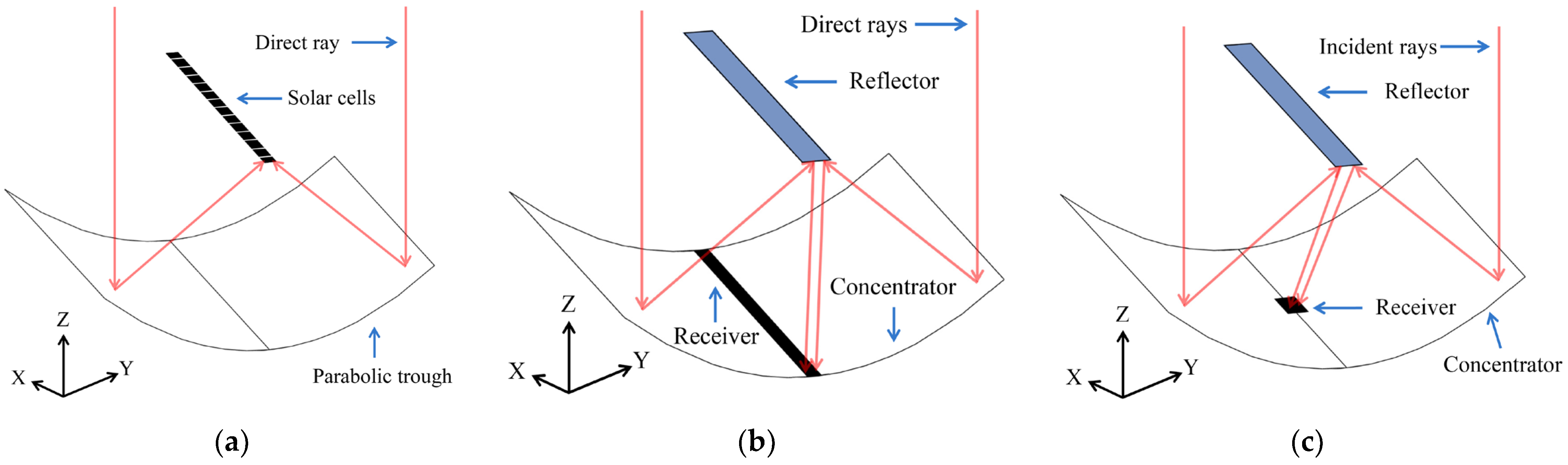
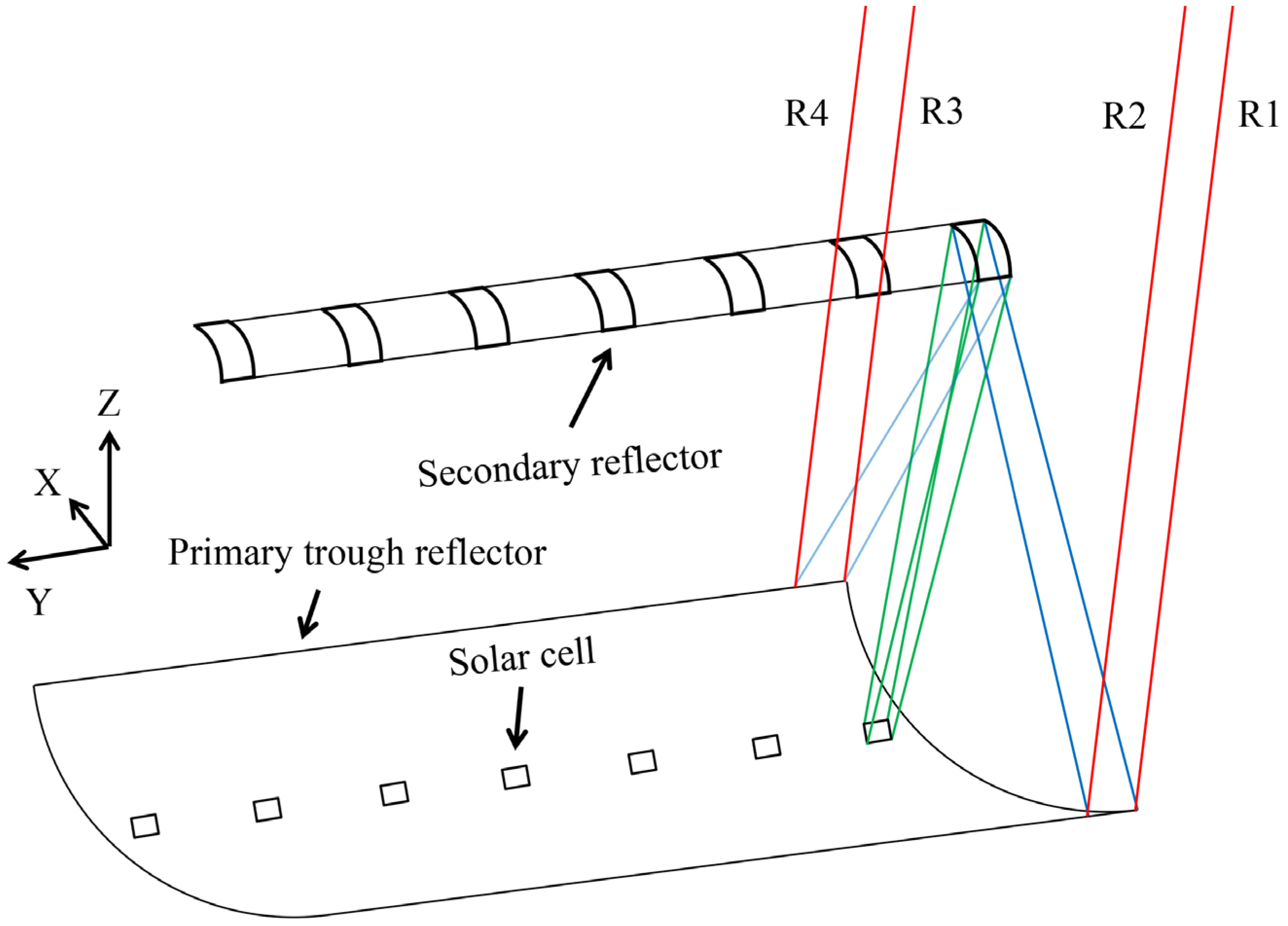
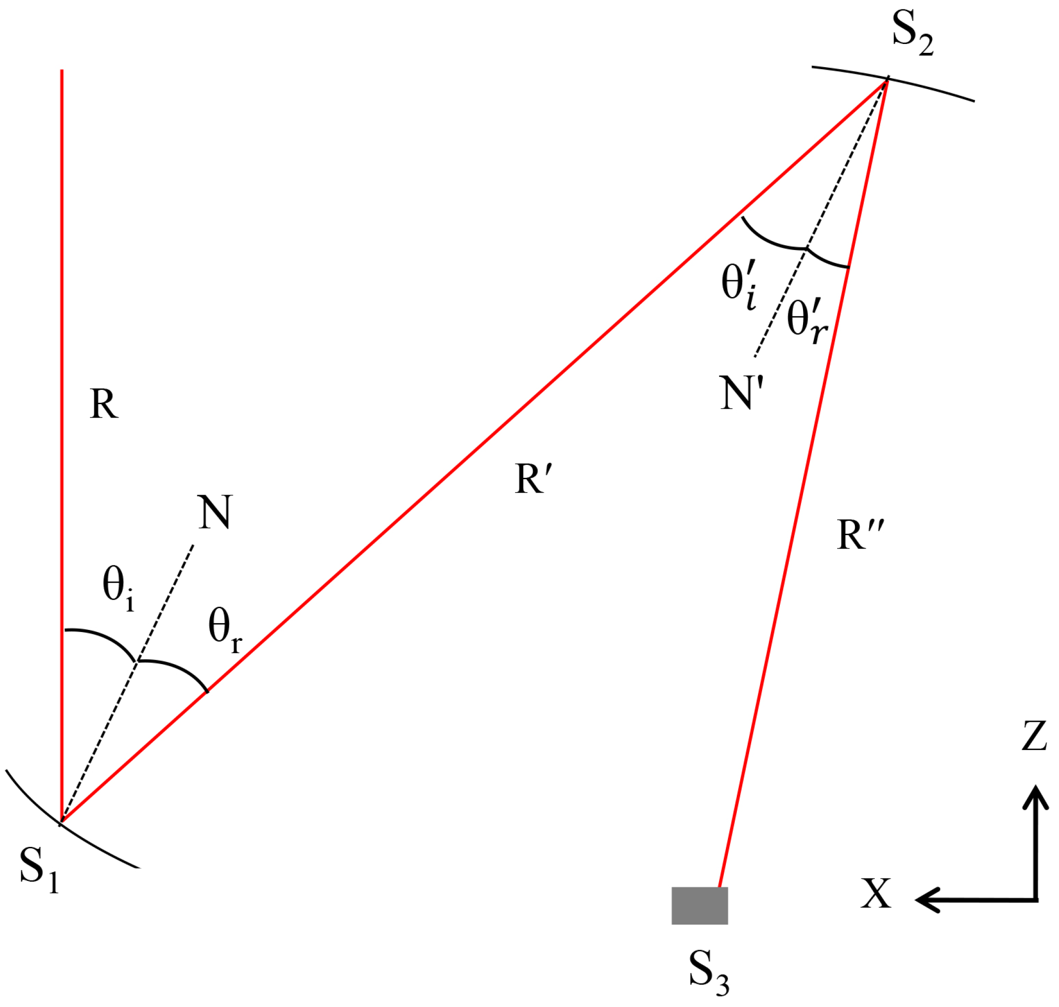
2. Design and Optical Modeling of the Proposed CPV System

A parabolic trough gives a linear concentration. In the proposed approach, the trough concentrator focused the light towards the secondary nonimaging reflector, which converts the linear concentration to square shape for providing uniform distribution over the solar cell. The secondary reflector is divided into 15 segments where each segment has a width of 33.3 mm, which consists of reflective grooves [11] to reflect the light over the solar cell. The segments of the secondary reflector are identical, with different orientations to obtain the same level of irradiance distribution for each cell where the number of segments depend on the length of the trough, which can be increased or decreased. In CPV and CSP systems, the reflectors are made of reflective materials (e.g., silver, aluminum, and steel) [39,40] that reflect the sunlight towards the targeted point. Each reflective material has its own reflectivity and optical properties [41]. Imperfect optics, absorption losses, and non-uniform illumination degrades the performance of CPV system, which is being minimized in this design [42]. Figure 2 shows the 3D line view diagram of the optical HCPV system.
The parabolic reflector can be designed by [43]
D = W 2 4 f
L e n g t h a r c = 1 2 q 2 + 16 p 2 + q 2 8 p ln 4 p + q 2 + 16 p 2 q
The length and width of the trough was 500 mm (Table 1). The width of the secondary nonimaging reflector was 33.3 mm. The solar cells of size 5 × 5 mm2 were mounted at the center of the trough for each segment of the secondary reflector. In Figure 3, layout of the optical CPV system and segments of the secondary nonimaging reflector are shown.
The 2D geometry of the proposed two-stage CPV system is shown in Figure 4, in which R is the incident light ray made an incident angle θi with the unit normal vector (N) of the primary reflector having surface S1. The primary concentrator reflected the incident ray, and the reflected light ray, R′, made an angle θr with the unit normal vector, N, of the surface S1. The secondary reflector redirected the light towards the surface of the solar cell, S3. The ray R′ made an incident angle θ′i and the reflected ray, R″, made an angle θ′r with the unit normal vector, N′, of the surface S2.
Figure 5 illustrates the geometry of the secondary reflector having reflective grooves. The width and depth of the secondary reflector are Ws and Dnr, respectively. It is noted that the width of all the reflective grooves W1 · · · Wn are same, whereas all the grooves make different titled angles α1n along y-z plane to redirect the maximum light towards the solar cell.
A nonimaging reflector can be designed using edge-ray principle where the edge rays are redirected from the source to the edges of the receiver. Using edge-ray principle, a nonimaging reflector can be designed for achieving high efficiency. Figure 6 shows a schematic diagram of the system showing how the edge-rays reach from source principle. The incident rays, R1–R4, are transmitted from a source towards the trough. Figure 6 shows the schematic diagram of a segment of the optical system in which incident rays R1–R4 are reflected by the trough towards the edges of the reflected grooves G2, G4, G1, and G3, respectively. The reflected grooves redirected the reflected rays towards the solar cell S1–S4.
The maximum concentration in 2D system is [20]
C m a x = 1 s i n θ
In CPV systems, acceptance angle is generally defined as the angle at which 90% transmission or reflection is achieved at normal incidence [20]. The geometrical concentration ratio can be calculated by [44], whereas the aperture area of the collector is calculated as 250,000 mm2 by multiplying its length and width, while the receiver has an area of 375 mm2 (by including all segments); thus, the Cg was noted as 666.7× without shading. Moreover, the shading effect of secondary reflector was studied and the geometrical concentration was considered as 622×.
C g = A p e r t u r e   a r e a   o f   t h e   c o l l e c t o r P r o j e c t e d   a r e a   o f   t h e   r e c i v e r
To further increase the concentration, the projected area of the receiver could be reduced or the aperture area of the collector could be increased.
A raytracing using laws of reflection into vector form can be expressed by [44].
v = v 2 n · v × n

3. Simulation Results and Discussion

Monte Carlo raytracing simulation was performed using an optical software LightTools®. Collimated light source was produced to illuminate the optical concentrator. The trough was designed by optimizing its width, depth, and length. The secondary nonimaging reflective grooves were designed and optimized using the non-sequential raytracing. Each segment of the reflective grooves was developed and optimized using edge ray principle. The edge rays were reflected by the segment towards the edges of the solar cell. The non-sequential raytracing of individual module was performed to obtain optimized design and high efficiency. All the modules were integrated and raytracing simulation of the system was performed to obtain the results. Raytracing of the optical system is shown in Figure 7. Figure 8 shows raytracing using different wavelengths.
To simulate the entire optical system, direct normal irradiance of 1 sun insolation (1 kW/m2) was used. A solar cell with 3-junctions (GaInP/GaInAs/Ge), manufactured by AZUR SPACE Solar Power GmbH [45,46], was used in this proposed system; moreover, this triple junction solar cell is capable of handling up to 1000× concentration. The solar spectrum consists of different wavelengths, such as ultraviolet, visible, and infrared. In this study, a wavelength range of 300–2500 nm was considered for the source, which emitted collimated rays of 100,000, and dual axis tracking method was assumed. The optical modules were optimized by a series of raytracing simulations. For nonimaging optical modules, non-sequential rays were used.
Simulation results without reflective grooves were achieved (Figure 9) showing nonuniform irradiance distribution. As shown in Figure 10, better irradiance distribution was achieved over the solar cell compared to the distribution without reflective grooves. The X-slice and Y-slice that are taken at the center of X-axis and Y axis, respectively, are also shown in Figure 10. Irradiance distribution at different incident angles was plotted where the acceptance angle was ±0.4° (Figure 11).
The optical efficiency can be defined as, following ASTM G173 AM1.5D spectral irradiance [47],
η o p t i c a l = O u t p u t   l i g h t   p o w e r   o n   t h e   r e c e i v e r I n p u t   l i g h t   p o w e r   o n   t h e   c o l l e c t o r
Reflectance, absorption, and other properties were included in optical efficiency calculations. The system has an optical efficiency of 79% for the concentration of 622×.
Table 2 gives an overview of trough based CPV systems and their major improvements in terms of solar concentration, acceptance angle, and efficiency. Low concentrating systems had achieved geometric concentration of 9.93, 23.4, 50, 53, 68, and 74 [36,48,49,50,51,52], respectively, while medium concentrating systems achieved geometric concentration of 220 and 285 [29,53], respectively. HCPV systems were analyzed, which had geometric concentration of 364 and 600 [54,55], respectively. In [17,48,50,52,54], the systems could not achieve uniform irradiance distribution.

4. Conclusions and Future Works

MJ solar cells have reached record conversion efficiencies at high concentration, which becomes possible using imaging and nonimaging concentrators. This study used a parabolic trough to obtain high concentration using nonimaging reflective grooves. Identical segments of nonimaging reflective grooves were combined where each segment reflected the light over the cell. The system achieved a high concentration ratio of 622×, which was higher than that of previous systems. The concentration could be further increased by increasing the width of the concentrator or by reducing the Acell. In case of increasing the Ws, the efficiency was dropped due to lost rays. To further increase the concentration, the size of the receiver was decreased, which significantly degraded the uniformity. With the proposed two-stage concentrator, an optical efficiency of 79% was obtained.
Furthermore, different single-stage and two-stage trough-based concentrators were compared with the proposed system. The future work will focus on adding an optical element upstream the solar cell for uniform irradiance distribution and to increase the acceptance angle. In addition, a homogenizer will be added to increase the uniformity. The proposed design would also be a good contribution to generate energy using solar thermal technology.

Author Contributions

Methodology, W.I.; Supervision, I.U. and S.S.; Funding acquisition, S.S. All authors have read and agreed to the published version of the manuscript.

Funding

This work was supported by a National Research Foundation of Korea (NRF) grant funded by the Korean government (MSIT) (project number: 2021R1A2C1010879).

Conflicts of Interest

The authors declare no conflict of interest.

Nomenclature

Greek symbols
θAcceptance angle
ηOpticalOptical efficiency
θiAngle of incidence at S1
θrAngle of reflection at S1
θ′iAngle of incidence at S2
θ′rAngle of reflection at S2
αTilted angle of a groove along y-z plane
Abbreviations
CPC Compound parabolic concentrator
CPV Concentrator photovoltaic
CSP Concentrated solar power
HCPV High concentrating photovoltaic
PV Photovoltaic
POE Primary optical element
SOE Secondary optical element
Latin symbols
Acell Area of the solar cell
CgGeometrical concentration ratio
CmaxMaximum concentration ratio
DDepth of the parabola
DnrDepth of the secondary nonimaging reflector
fFocal length of the parabola
GEdge of a reflected grooves
HDistance between the trough and secondary reflectors
LLength of the parabola
LengtharcArc length of the parabola
MJ Multi-junction
NUnit normal vector into the primary concentrator
N′Unit normal vector into the secondary reflector
pLength along the parabola axis
qLength perpendicular to the axis making a chord
RIncident light ray
SEdge of a solar cell
vUnit vectors along incident rays
v″Unit vectors along reflected rays
WWidth of the parabola
Ws Width of the secondary nonimaging reflector
Wn Width of a groove

References

  1. Gasparotto, J.; Da Boit Martinello, K. Coal as an energy source and its impacts on human health. Energy Geosci. 2021, 2, 113–120. [Google Scholar] [CrossRef]
  2. International Energy Agency. World Energy Outlook 2021; OECD Publishing: Paris, France, 2021. [Google Scholar] [CrossRef]
  3. Rejeb, O.; Shittu, S.; Ghenai, C.; Li, G.; Zhao, X.; Bettayeb, M. Optimization and performance analysis of a solar concentrated photovoltaic-thermoelectric (CPV-TE) hybrid system. Renew. Energy 2020, 152, 1342–1353. [Google Scholar] [CrossRef]
  4. Pintanel, M.T.; Martínez-Gracia, A.; Uche, J.; del Amo, A.; Bayod-Rújula, Á.A.; Usón, S.; Arauzo, I. Energy and environmental benefits of an integrated solar photovoltaic and thermal hybrid, seasonal storage and heat pump system for social housing. Appl. Therm. Eng. 2022, 213, 118662. [Google Scholar] [CrossRef]
  5. Bergmann, R. Crystalline Si thin-film solar cells: A review. Appl. Phys. A 1999, 69, 187–194. [Google Scholar] [CrossRef]
  6. Peibst, R.; Rienäcker, M.; Larionova, Y.; Folchert, N.; Haase, F.; Hollemann, C.; Wolter, S.; Krügener, J.; Bayerl, P.; Bayer, J.; et al. Towards 28%-efficient Si single-junction solar cells with better passivating POLO junctions and photonic crystals. Sol. Energy Mater. Sol. Cells 2022, 238, 111560. [Google Scholar] [CrossRef]
  7. Sharma, M.K.; Bhattacharya, J. Deciding between concentrated and non-concentrated photovoltaic systems via direct comparison of experiment with opto-thermal computation. Renew. Energy 2021, 178, 1084–1096. [Google Scholar] [CrossRef]
  8. Wiesenfarth, M.; Anton, I.; Bett, A.W. Challenges in the design of concentrator photovoltaic (CPV) modules to achieve highest efficiencies. Appl. Phys. Rev. 2018, 5, 041601. [Google Scholar] [CrossRef] [Green Version]
  9. Dimroth, F.; Tibbits, T.N.D.; Niemeyer, M.; Predan, F.; Beutel, P.; Karcher, C.; Oliva, E.; Siefer, G.; Lackner, D.; Fus-Kailuweit, P.; et al. Four-Junction Wafer-Bonded Concentrator Solar Cells. IEEE J. Photovolt. 2016, 6, 343–349. [Google Scholar] [CrossRef]
  10. Siefer, G.; Beutel, P.; Lackner, D.; Oliva, E.; Predan, F.; Schachtner, M.; Dimroth, F.; Ledoux, O.; Guiot, E. Four-Junction Wafer Bonded Solar Cells for Space Applications. In 2019 European Space Power Conference (ESPC); IEEE: Piscataway, NJ, USA, 2019; pp. 1–4. [Google Scholar]
  11. Ullah, I. Optical design of centered-receiver trough-based CPV system. J. Photonics Energy 2021, 11, 035502. [Google Scholar] [CrossRef]
  12. Saura, J.M.; Rodrigo, P.M.; Almonacid, F.M.; Chemisana, D.; Fernández, E.F. Experimental characterisation of irradiance and spectral non-uniformity and its impact on multi-junction solar cells: Refractive vs. reflective optics. Sol. Energy Mater. Sol. Cells 2021, 225, 111061. [Google Scholar] [CrossRef]
  13. Mortadi, M.; El Fadar, A. Novel design of concentrating photovoltaic thermal collector—A comparative analysis with existing configurations. Energy Convers. Manag. 2022, 268, 116016. [Google Scholar] [CrossRef]
  14. Dhakal, R.; Lee, J.; Kim, J. Bio-inspired thin and flat solar concentrator for efficient, wide acceptance angle light collection. Appl. Opt. 2014, 53, 306–315. [Google Scholar] [CrossRef] [PubMed]
  15. Chemisana, D.; Ibáñez, M.; Barrau, J. Comparison of Fresnel concentrators for building integrated photovoltaics. Energy Convers. Manag. 2009, 50, 1079–1084. [Google Scholar] [CrossRef]
  16. Xie, W.T.; Dai, Y.J.; Wang, R.Z.; Sumathy, K. Concentrated solar energy applications using Fresnel lenses: A review. Renew. Sustain. Energy Rev. 2011, 15, 2588–2606. [Google Scholar] [CrossRef]
  17. Indira, S.S.; Vaithilingam, C.A.; Sivasubramanian, R.; Chong, K.-K.; Saidur, R.; Narasingamurthi, K. Optical performance of a hybrid compound parabolic concentrator and parabolic trough concentrator system for dual concentration. Sustain. Energy Technol. Assess. 2021, 47, 101538. [Google Scholar]
  18. Yang, J.; Xiao, Y.; Liang, J. Chapter 5 Concentrator PV and solar tracker. In Solar Photovoltaic Power Generation; De Gruyter: Berlin, Germany, 2020; pp. 163–200. [Google Scholar]
  19. Badr, F.; Radwan, A.; Ahmed, M.; Hamed, A.M. Performance assessment of a dual-axis solar tracker for concentrator photovoltaic systems. Int. J. Energy Res. 2022, 46, 13424–13440. [Google Scholar] [CrossRef]
  20. Winston, R.; Miñano, J.C.; Benitez, P.G. Nonimaging Optics; Elsevier Academic Press: New York, NY, USA, 2005. [Google Scholar]
  21. Anandhi Parthiban, T.K.; Mallick, K.S. Reddy Integrated optical-thermal-electrical modeling of compound parabolic concentrator based photovoltaic-thermal system. Energy Convers. Manag. 2022, 251, 115009. [Google Scholar] [CrossRef]
  22. Da Rosa, A.V.; Ordóñez, J.C. Chapter 12-Solar Radiation. In Fundamentals of Renewable Energy Processes, 4th ed.; Academic Press: Cambridge, MA, USA, 2022; pp. 519–576. [Google Scholar]
  23. Chen, F.; Chen, J. A novel solution method for reflector shape of solar Compound Parabolic Concentrator and verification. Renew. Energy 2022, 192, 385–395. [Google Scholar] [CrossRef]
  24. Linderman, R.J.; Judkins, Z.S.; Shoecraft, M.; Dawson, M.J. Thermal Performance of the SunPower Alpha-2 PV Concentrator. IEEE J. Photovolt. 2012, 2, 196–201. [Google Scholar] [CrossRef]
  25. Oh, S.J.; Kim, H.; Hong, Y. Monte Carlo Ray-Tracing Simulation of a Cassegrain Solar Concentrator Module for CPV. Front. Energy Res. 2021, volume 9, 722842. [Google Scholar] [CrossRef]
  26. Ferrer-Rodríguez, J.P.; Fernández, E.F.; Almonacid, F.; Baig, H.; Mallick, T.K.; Pérez-Higueras, P. Indoor characterization and comparison with optical modelling of four Fresnel-based High-CPV units equipped with secondary optics. In AIP Conference Proceedings; AIP Publishing LLC.: Melville, NY, USA, 2018. [Google Scholar]
  27. Rahmanian, S.; Moein-Jahromi, M.; Rahmanian-Koushkaki, H.; Sopian, K. Performance investigation of inclined CPV system with composites of PCM, metal foam and nanoparticles. Sol. Energy 2021, 230, 883–901. [Google Scholar] [CrossRef]
  28. Felsberger, R.; Buchroithner, A.; Gerl, B.; Schweighofer, B.; Preßmair, R.; Mitter, T.; Wegleiter, H. Optical performance and alignment characterization of a parabolic trough collector using a multi-junction CPV solar cell. Sol. Energy 2022, 239, 40–49. [Google Scholar] [CrossRef]
  29. Ullah, I. Optical modeling of two-stage concentrator photovoltaic system using parabolic trough. J. Photonics Energy 2019, 9, 043102. [Google Scholar] [CrossRef]
  30. Carlo, R. Characterization of spherical optics performance compared to other types of optical systems in a point-focus CPV system. Therm. Sci. Eng. Prog. 2022, 29, 101201. [Google Scholar]
  31. Bel Hadj, O.; Kechiche, B.; Sammouda, H. Concentrator Photovoltaic System (CPV): Maximum Power Point Techniques (MPPT) Design and Performance. In Solar Radiation-Measurement, Modeling and Forecasting Techniques for Photovoltaic Solar Energy Applications; IntechOpen Limited: London, UK, 2022. [Google Scholar]
  32. Renno, C.; Perone, A. Experimental modeling of the optical and energy performances of a point-focus CPV system applied to a residential user. Energy 2021, 215, 119156. [Google Scholar] [CrossRef]
  33. Vu, H.; Vu, N.H.; Shin, S. Static Concentrator Photovoltaics Module for Electric Vehicle Applications Based on Compound Parabolic Concentrator. Energies 2022, 15, 6951. [Google Scholar] [CrossRef]
  34. Lokeswaran, S.; Mallick, T.K.; Reddy, K.S. Design and analysis of dense array CPV receiver for square parabolic dish system with CPC array as secondary concentrator. Sol. Energy 2020, 199, 782–795. [Google Scholar] [CrossRef]
  35. Venegas-Reyes, E.; Ortega-Avila, N.; Peña-Cruz, M.; García-Ortiz, O.; Rodriguez-Muñoz, N. A Linear Hybrid Concentrated Photovoltaic Solar Collector: A Methodology Proposal of Optical and Thermal Analysis. Energies 2021, 14, 8155. [Google Scholar] [CrossRef]
  36. Widyolar, B.; Jiang, L.; Abdelhamid, M.; Winston, R. Design and modeling of a spectrum-splitting hybrid CSP-CPV parabolic trough using two-stage high concentration optics and dual junction InGaP/GaAs solar cells. Sol. Energy 2018, 165, 75–84. [Google Scholar] [CrossRef]
  37. Naveenkumar, R.; Ravichandran, M.; Stalin, B.; Ghosh, A.; Karthick, A.; Aswin, L.S.R.L.; Kumar, S.P.; Kumar, S.K. Comprehensive review on various parameters that influence the performance of parabolic trough collector. Environ. Sci. Pollut. Res. 2021, 28, 22310–22333. [Google Scholar] [CrossRef]
  38. Zhao, K.; Jin, H.; Gai, Z.; Hong, H. A thermal efficiency-enhancing strategy of parabolic trough collector systems by cascadingly applying multiple solar selective-absorbing coatings. Appl. Energy 2022, 309, 118508. [Google Scholar] [CrossRef]
  39. Häberle, A.; Krüger, D. Concentrating solar technologies for industrial process heat. Conc. Sol. Power Technol. 2021, volume, 659–675. [Google Scholar] [CrossRef]
  40. Groulx, D.; Sponagle, B. Ray-Tracing Analysis of a Two-Stage Solar Concentrator. Trans. Can. Soc. Mech. Eng. 2010, 34, 263–275. [Google Scholar] [CrossRef] [Green Version]
  41. Brogren, M.; Karlsson, B.; Roos, A.; Werner, A. Analysis of the effects of outdoor and accelerated ageing on the optical properties of reflector materials for solar energy applications. Sol. Energy Mater. Sol. Cells 2004, 82, 491–515. [Google Scholar] [CrossRef]
  42. Baig, H.; Heasman, K.C.; Mallick, T.K. Non-uniform illumination in concentrating solar cells. Renew. Sustain. Energy Rev. 2012, 16, 5890–5909. [Google Scholar] [CrossRef]
  43. Spiegel, M.R.; Lipschutz, S.; Liu, J. Mathematical Handbook of Formulas and Tables, 3rd ed.; McGraw Hill: New York, NY, USA, 2009. [Google Scholar]
  44. Lovegrove, K.; Stein, W. Concentrating Solar Power Technology: Principles, Developments and Applications; Woodhead Publishing Limited: Cambridge, UK, 2012. [Google Scholar]
  45. Azure Space Solar Power GmbH. Concentrator Triple Junction Solar Cell 3C44. 2015. Available online: https://www.azurspace.com/images/products/0004356-00-01_3C44_AzurDesign_5.pdf (accessed on 10 October 2022).
  46. Azure Space Solar Power GmbH. Concentrator Triple Junction Solar Cell 3C44. 2015. Available online: http://www.azurspace.com/images/products/0004355-00-01_3C44_AzurDesign_10x10.pdf (accessed on 10 October 2022).
  47. NREL. Reference solar spectral irradiance: Air mass 1.5. ASTM (G-173-03). Available online: https://rredc.nrel.gov/solar/spectra/am1.5/ (accessed on 11 August 2022).
  48. Chaudhary, G.Q.; Kousar, R.; Ali, M.; Amar, M.; Amber, K.P.; Lodhi, S.K.; Din, M.R.; Ditta, A. Small-Sized Parabolic Trough Collector System for Solar Dehumidification Application: Design, Development, and Potential Assessment. Int. J. Photoenergy 2018, 2018, 5759034. [Google Scholar] [CrossRef] [Green Version]
  49. Chargui, R.; Tashtoush, B.; Awani, S. Experimental study and performance testing of a novel parabolic trough collector. Int. J. Energy Res. 2021, 46, 1518–1537. [Google Scholar] [CrossRef]
  50. Felsberger, R.; Buchroithner, A.; Gerl, B.; Wegleiter, H. Conversion and testing of a solar thermal parabolic trough collector for CPV-T application. Energies 2020, 13, 6142. [Google Scholar] [CrossRef]
  51. Schmitz, M.; Cooper, T.; Ambrosetti, G.; Steinfeld, A. Two-stage solar concentrators based on parabolic troughs: Asymmetric versus symmetric designs. Appl. Opt. 2015, 54, 9709–9721. [Google Scholar] [CrossRef]
  52. Otanicar, T.P.; Wingert, R.; Orosz, M.; McPheeters, C. Concentrating photovoltaic retrofit for existing parabolic trough solar collectors: Design, experiments, and levelized cost of electricity. Appl. Energy 2020, 265, 114751. [Google Scholar] [CrossRef]
  53. Felsberger, R.; Buchroithner, A.; Gerl, B.; Schweighofer, B.; Wegleiter, H. Design and testing of concentrated photovoltaic arrays for retrofitting of solar thermal parabolic trough collectors. Appl. Energy 2021, 300, 117427. [Google Scholar] [CrossRef]
  54. Cooper, T.; Ambrosetti, G.; Malnati, F.; Pedretti, A.; Steinfeld, A. Experimental demonstration of high-concentration photovoltaics on a parabolic trough using tracking secondary optics. Prog. Photovolt. Res. Appl. 2016, 24, 1410–1426. [Google Scholar] [CrossRef]
  55. Cooper, T.; Ambrosetti, G.; Pedretti, A.; Steinfeld, A. Surpassing the 2D limit: A 600x high-concentration PV collector based on a parabolic trough with tracking secondary optics. Energy Procedia 2014, 57, 285–290. [Google Scholar] [CrossRef] [Green Version]
Figure 1. (a) Trough with linear focus, (b) trough with linear focus with two stage concentration, and (c) trough with focus on the center with two stage concentration.
Energies 16 01336 g001
Figure 2. Optical components and their orientation for the HCPV system.
Energies 16 01336 g002
Figure 3. Three-dimensional schematic diagram of the CPV system depicting the rays from source to the receiver.
Energies 16 01336 g003
Figure 4. Two-dimensional geometry of the proposed two-stage CPV system.
Energies 16 01336 g004
Figure 5. (a) Illustrating geometry of the reflective grooves, (b) 3D wireframe view, and (c) translucent view of the secondary reflector.
Energies 16 01336 g005
Figure 6. Edge-ray principle showing incident rays reflected from edges of the reflectors towards the receiver: (a) first-stage concentration (primary reflector to secondary reflector) and (b) second-stage concentrator (secondary reflector to the receiver).
Energies 16 01336 g006
Figure 7. Illustrating non-sequential raytracing of the CPV system.
Energies 16 01336 g007
Figure 8. Showing simulation using full spectrum wavelengths.
Energies 16 01336 g008
Figure 9. Simulation results without reflective grooves showing nonuniform illumination over the solar cell.
Energies 16 01336 g009
Figure 10. Irradiance distribution of 622× concentration over the solar cell.
Energies 16 01336 g010
Figure 11. Irradiance profile for incident angles: (a) 0.1°, (b) 0.2°, (c) 0.3°, and (d) 0.4°.
Energies 16 01336 g011
Table 1. Design parameters of the optical system.
ParameterValue
W500 mm
L500 mm
D57 mm
Ws33.3 mm
H286
Cg622
Acell5 × 5 mm2
Table 2. Comparison of the parabolic trough-based concentrating systems.
PaperConcentratorSecondary OpticsTechnologyCell TypeConcentrationAcceptance Angle (°)Irradiance UniformityElectrical Efficiency (%)Optical Efficiency (%)
Cooper et al., 2014 [55]TroughCPVMJ600×-2578
Schmitz et al., 2015 [51]TroughCPVMJ68×0.6--
Cooper et al., 2016 [54]TroughCPVMJ364×3.2Energies 16 01336 i00120.2-
Chaudhary et al., 2018 [48]TroughEnergies 16 01336 i001CPV-T-9.93×-Energies 16 01336 i001-46–62
Widyolar et al., 2018 [36]TroughCPVMJ50×0.623-
Ullah, 2019 [29]TroughCPVMJ285×±1.1-72
Felsberger et al., 2020 [50]TroughEnergies 16 01336 i001CPV-TMJ53×-Energies 16 01336 i00128-
Otanicar et al., 2020 [52]TroughCPV-TSi74×-Energies 16 01336 i00121-
Indira et al., 2021 [17]Hybrid CPC/TroughCPVMJ--Energies 16 01336 i001-73
Chargui et al., 2021 [49]TroughEnergies 16 01336 i001T-23.4×--60
Felsberger et al., 2021 [53]TroughEnergies 16 01336 i001CPV-TMJ220×-26.848.8
Ullah, 2021 [11]TroughCPVMJ285×±2-60
Proposed designTroughCPVMJ622×±0.4-79
Disclaimer/Publisher’s Note: The statements, opinions and data contained in all publications are solely those of the individual author(s) and contributor(s) and not of MDPI and/or the editor(s). MDPI and/or the editor(s) disclaim responsibility for any injury to people or property resulting from any ideas, methods, instructions or products referred to in the content.

